

Siemens SINUMERIK 810DE powerline, SINUMERIK 810D powerline Equipment Manual
RGB ELEKTRONIKA AGACIAK CIACIEK
SPÓŁKA JAWNA
Jana Dlugosza 2-6 Street
51-162 Wrocław
Poland
biuro@rgbelektronika.pl
+48 71 325 15 05
www.rgbautomatyka.pl
www.rgbelektronika.pl
DATASHEET
www.rgbautomatyka.pl
www.rgbelektronika.pl
OTHER SYMBOLS:
6FC5211-0AA10-0AA0
6FC52110AA100AA0, 6FC52110AA10 0AA0, 6FC52110AA10-0AA0, 6FC5211 0AA100AA0, 6FC5211 0AA10 0AA0,
6FC5211 0AA10-0AA0, 6FC5211-0AA100AA0, 6FC5211-0AA10 0AA0, 6FC5211-0AA10-0AA0
SIEMENS
YOUR
PARTNER IN
MAINTENANCE
At our premises in Wrocław, we have a fully equipped servicing facility. Here we perform all the repair
works and test each later sold unit. Our trained employees, equipped with a wide variety of tools and
having several testing stands at their disposal, are a guarantee of the highest quality service.
OUR SERVICES
ENCODERS
SERVO
DRIVERS
LINEAR
ENCODERS
SERVO AMPLIFIERS
CNC
MACHINES
MOTORS
POWER
SUPPLIERS
OPERATOR
PANELS
CNC
CONTROLS
INDUSTRIAL
COMPUTERS
PLC
SYSTEMS
Repair this product with RGB ELEKTRONIKA
ORDER A DIAGNOSIS
∠
Buy this product at RGB AUTOMATYKA
BUY
∠
Valid for
Control
SINUMERIK 810D powerline
SINUMERIK 810DE powerline
Edition 03/2006
SINUMERIK 810D
Configuration CCU
Equipment Manual
System Overview 1
Connection Conditions 2
Design and Installation 3
Description 4
Axis Expansion 5
I/O Modules 6
NCU Terminal Block 7
DMP Compact Modules 8
Maintenance and Service 9
Abbreviations A
Index
SINUMERIK® Documentation
Printing history
Brief details of this edition and previous editions are listed below.
The status of each edition is shown by the code in the “Remarks” column.
Status code in the “Remarks” column:
A New documentation.. . . . .
B Unrevised reprint with new order no.. . . . .
C Revised edition with new status. . . . . .
Edition Order No. Remarks
12.95 6FC5297–1AD10–0BP0 A
07.96 6FC5297–1AD10–0BP1 C
08.97 6FC5297–2AD10–0BP0 C
12.98 6FC5297–3AD10–0BP0 C
08.99 6FC5297–3AD10–0BP1 C
04.00 6FC5297–3AD10–0BP2 C
10.00 6FC5297–4AD10–0BP0 C
12.01 6FC5297–4AD10–0BP1 C
03.02 6FC5297–6AD10–0BP0 C
11.02 6FC5297–6AD10–0BP1 C
03.05 6FC5297–6AD10–0BP2 C
03.06 6FC5297–7AD10–0BP0 C
Trademarks
All product names mentioned may be trademarks or product designations of Siemens AG or their suppliers,
whose use by third parties for their own purposes may infringe the rights of the trademark owners.
Further information is available in the Internet under:
http://www.siemens.com/motioncontrol
This publication was produced with Interleaf V 7.
Copyright
©
Siemens AG 2006
Other functions not described in this documentation might be
executable in the control. However, no claim can be made regarding
the availability of these functions when the equipment is first supplied
or in the event of servicing.
We have checked that the contents of this document correspond to
the hardware and software described. Nevertheless, differences
might exist and therefore we cannot guarantee that they are
completely identical. The information given in this publication is
reviewed at regular intervals and any corrections that might be
necessary are made in the subsequent printings. Suggestions for
improvement are also welcome.
Subject to change without prior notice.
Siemens Aktiengesellschaft
Order No. 6FC5297-7AD10-0BP0
Printed in the Federal Re
p
ublic of German
y
iii
Copyright © Siemens AG 2006
SINUMERIK 810D Equipment Manual Configuration CCU (PHC) – 03/2006 Edition
Preface
The SINUMERIK documentation is subdivided into 3 parts:
S General Documentation
S User documentation
S Manufacturer/Service documentation
A list of documents with the respective available languages is updated on a
monthly basis and is available on the Internet at:
http://www.siemens.com/motioncontrol
Select “Support” → “Technical Documentation → “Overview of Documents”.
The Internet version of the DOConCD (DOConWEB) is available at:
http://www.automation.siemens.com/doconweb
Information on the training offerings and on FAQs (frequently asked questions)
can be found in the Internet under:
http://www.siemens.com/motioncontrol
and menu item “Support”.
This documentation is intended for:
S Project engineers, electricians and installers
S Maintenance and service personnel
The information in this manual enables installation of the SINUMERIK 810D
Numerical Control and measures for maintenance and service.
This documentation only describes the functionality of the standard version.
Extensions or changes made by the machine tool manufacturer are documen-
ted by the machine tool manufacturer. Other functions not described in this
documentation might be executable in the control. This does not, however,
represent an obligation to supply such functions with an initial delivery or when
servicing.
For the sake of simplicity, this documentation does not contain all detailed infor-
mation about all types of the product and cannot cover every conceivable case
of installation, operation, or maintenance.
If you have any questions about the control, please contact the hotline:
Europe and Africa time zone
A&D Technical Support
Tel.: +49 (0) 180 / 5050 222
Fax: +49 (0) 180 / 5050-223
Internet: http://www.siemens.com/automation/support-request
E-Mail: mailto:adsupport@siemens.com
SINUMERIK
Documentation
Target group
Benefits
Standard version
Technical Support
iv
Copyright © Siemens AG 2006
SINUMERIK 810D Equipment Manual Configuration CCU (PHC) – 03/2006 Edition
Asia and Australia time zone
A&D Technical Support
Tel.: +86 1064 719 990
Fax: +86 1064 747 474
Internet: http://www.siemens.com/automation/support-request
E-Mail: mailto:adsupport@siemens.com
America time zone
A&D Technical Support
Tel.: +1 423 262 2522
Fax: +1 423 262 2289
Internet: http://www.siemens.com/automation/support-request
E-Mail: mailto:adsupport@siemens.com
Note
Country-specific telephone numbers for technical support are provided under
the following internet address:
Enter http://www.siemens.com/automation/service&support
For questions on the documentation (suggestions, corrections), please send a
fax or e-mail to the following address:
Fax: +49 (0) 9131 / 98 – 63315
E-Mail: mailto:motioncontrol.docu@siemens.com
Fax form: see the reply form at the end of the brochure
http://www.siemens.com/sinumerik
The EC conformity declarations on EMC are to be found at/can be obtained
from:
S in the Internet:
http://www.ad.siemens.de/csinfo
under the product/order no. 15257461
S at the relevant branch office of the A&D MC group of Siemens AG.
This manual contains information which you should observe in order to ensure
your own personal safety, as well to avoid material damage. Notices which are
relevant to your own personal safety are highlighted by a safety alert symbol;
notices which are relevant only to equipment and property damage have no
safety alert symbol. The warnings appear in decreasing order of risk as given
below.
!
Danger
indicates that death or serious injury will result if proper precautions are not
taken.
Questions about
the manual
SINUMERIK
Internet address
EC Conformity
Declaration
Safety instructions
Preface
v
Copyright © Siemens AG 2006
SINUMERIK 810D Equipment Manual Configuration CCU (PHC) – 03/2006 Edition
!
Warning
indicates that death or serious injury may result if proper precautions are not
taken.
!
Caution
with a safety alert symbol, indicates that minor personal injury may result if
proper precautions are not taken.
Caution
without a safety alert symbol, indicates that property damage can result if
proper precautions are not taken.
Notice
indicates that an undesirable event or state may arise if the relevant notes are
not observed.
If several hazards of different degrees occur, the hazard with the highest degree
must always be given priority. If a warning note with a warning triangle warns of
personal injury, the same warning note can also contain a warning of material
damage.
Commissioning and operation of the device/equipment/system in question must
only be performed using this documentation. Only qualified personnel should
be allowed to commission and operate the device/system. Qualified persons
are defined as persons who are authorized to commission, to ground, and to tag
circuits, equipment, and systems in accordance with established safety practi-
ces and standards.
Please note the following:
!
Warning
The equipment may only be used for single purpose applications explicitly
described in the catalog and in the technical description and it may only be
used along with third-party devices and components recommended by
Siemens. To ensure trouble-free and safe operation of the product, it must be
transported, stored and installed as intended and maintained and operated with
care.
Qualified
personnel
Intended use
Preface
vi
Copyright © Siemens AG 2006
SINUMERIK 810D Equipment Manual Configuration CCU (PHC) – 03/2006 Edition
Should it be necessary to test or take measurements on live equipment, then
the specifications and procedures defined in Accident Prevention Regulation of
the Berufsgenossenschaft BGV A3 (German employer’s liability insurance
association) must be adhered to, in particular § 8 “Permissible deviations when
working with live components”. Suitable electric tools should be used.
!
Danger
Operating electrical equipment has parts and components that are at
hazardous voltage levels.
After disconnecting all the supply voltages, a hazardous voltage will be present
in the DC link of all SIMODRIVE modules for another 5 minutes!
See Operating Guide
!
Danger
Repairs to devices that have been supplied by our company must only be
carried out by SIEMENS Customer Service or by repair centers
authorized by SIEMENS. When replacing parts or components, only use
those parts that are included in the spare parts list.
Before opening the equipment, always ensure that the power is off.
EMERGENCY STOP devices complying with EN 60204 (VDE 0113 Part 1)
must remain effective in all automation equipment modes. Resetting the
EMERGENCY STOP device must not cause an uncontrolled or undefined
restart.
Anywhere in the automation equipment where faults might cause major
material damage or even physical injury, in other words, where faults could
be dangerous, additional external precautions must be taken, or facilities
must be provided, that guarantee or enforce a safe operational state, even
when there is a fault (e.g. using an independent limit value switch,
mechanical interlocks etc.)
!
Warning
Connecting cables and signal cables should be installed so that inductive and
capacitive interference does not in any way impair the automation functions.
Warning
The modules contain electrostatically sensitive devices. Discharge yourself of
electrostatic energy before touching the components. The easiest way to do
this is to touch a conductive, grounded object immediately beforehand (for
example, the bare metal part of control cabinet or the protective ground contact
of a socket outlet).
Danger notices
Preface
vii
Copyright © Siemens AG 2006
SINUMERIK 810D Equipment Manual Configuration CCU (PHC) – 03/2006 Edition
Electrostatically Sensitive Devices
!
Important
Handling of modules containing devices sensitive to electrostatic discharge:
When handling components which can be destroyed by electrostatic
discharge, it must be ensured that personnel, the workstation and
packaging are well grounded.
Generally, electronic modules must not be touched unless work has to be
carried out on them. Only touch electronic modules after you have
grounded yourself.
Touch components only if:
– you are constantly grounded via an ESD arm band,
– ESD-shoes or ESD-shoe grounding strips if there is an ESD floor.
Modules may be placed only on electrically conductive surfaces (table with
ESD top, conductive ESD foam plastic, ESD packing bags, ESD transport
containers).
Keep modules away from visual display units, monitors or TV sets
(minimum distance from screen 10 cm).
Do not bring ESD-sensitive modules into contact with chargeable and
highly-insulating materials, such as plastic, insulating table tops or clothing
made of synthetic materials.
Measurements on modules are allowed only if
– the measuring instrument is properly grounded (e.g. equipment
grounding conductor), or
– before measuring with a potential-free measuring instrument, the probe
is briefly discharged (e.g. touch the unpainted metal parts of the control
housing).
!
Important
This notice indicates important facts that must be taken into consideration.
Note
This note contains additional important information.
ESD notices
Other information
Preface

viii
Copyright © Siemens AG 2006
SINUMERIK 810D Equipment Manual Configuration CCU (PHC) – 03/2006 Edition
Preface
Notes
ix
Copyright © Siemens AG 2006
SINUMERIK 810D Equipment Manual Configuration CCU (PHC) – 03/2006 Edition
1 System overview 1-11. . . . . . . . . . . . . . . . . . . . . . . . . . . . . . . . . . . . . . . . . . . . . . . . . . . .
1.1 SINUMERIK 810D powerline 1-11. . . . . . . . . . . . . . . . . . . . . . . . . . . . . . . . . .
1.2 System configuration 1-12. . . . . . . . . . . . . . . . . . . . . . . . . . . . . . . . . . . . . . . . .
1.3 Labels 1-21. . . . . . . . . . . . . . . . . . . . . . . . . . . . . . . . . . . . . . . . . . . . . . . . . . . . . .
2 Connection Conditions 2-23. . . . . . . . . . . . . . . . . . . . . . . . . . . . . . . . . . . . . . . . . . . . . .
2.1 Supplementary electrical conditions 2-23. . . . . . . . . . . . . . . . . . . . . . . . . . . .
2.1.1 Power supply 2-24. . . . . . . . . . . . . . . . . . . . . . . . . . . . . . . . . . . . . . . . . . . . . . .
2.1.2 Safe isolation to EN 61800-5-1 2-26. . . . . . . . . . . . . . . . . . . . . . . . . . . . . . . .
2.1.3 Grounding Concept 2-28. . . . . . . . . . . . . . . . . . . . . . . . . . . . . . . . . . . . . . . . . .
2.1.4 RI suppression measures 2-29. . . . . . . . . . . . . . . . . . . . . . . . . . . . . . . . . . . . .
2.2 Climatic and mechanical environmental conditions 2-31. . . . . . . . . . . . . . .
2.2.1 Transport and storage conditions 2-31. . . . . . . . . . . . . . . . . . . . . . . . . . . . . .
2.2.2 Operating conditions 2-32. . . . . . . . . . . . . . . . . . . . . . . . . . . . . . . . . . . . . . . . .
2.3 Technical data of the individual components 2-34. . . . . . . . . . . . . . . . . . . . .
2.4 MPI/OPI network rules 2-35. . . . . . . . . . . . . . . . . . . . . . . . . . . . . . . . . . . . . . .
3 Design and Installation of the 810D 3-37. . . . . . . . . . . . . . . . . . . . . . . . . . . . . . . . . . .
3.1 Structure of the SINUMERIK 810D 3-37. . . . . . . . . . . . . . . . . . . . . . . . . . . . .
3.2 Assembly of the SINUMERIK 810D 3-38. . . . . . . . . . . . . . . . . . . . . . . . . . . .
3.2.1 Alteration for external heat dissipation, 2-axis CCU box 3-43. . . . . . . . . . .
3.3 Power supply 3-45. . . . . . . . . . . . . . . . . . . . . . . . . . . . . . . . . . . . . . . . . . . . . . .
4 Description of the SINUMERIK 810D 4-47. . . . . . . . . . . . . . . . . . . . . . . . . . . . . . . . . .
4.1 Components of the SINUMERIK 810D 4-47. . . . . . . . . . . . . . . . . . . . . . . . . .
4.1.1 Overview 4-47. . . . . . . . . . . . . . . . . . . . . . . . . . . . . . . . . . . . . . . . . . . . . . . . . . .
4.2 Interfaces 4-50. . . . . . . . . . . . . . . . . . . . . . . . . . . . . . . . . . . . . . . . . . . . . . . . . . .
4.2.1 Overview 4-50. . . . . . . . . . . . . . . . . . . . . . . . . . . . . . . . . . . . . . . . . . . . . . . . . . .
4.2.2 Description of the interfaces, operating and display elements 4-52. . . . . .
4.2.3 Cable distributor 4-60. . . . . . . . . . . . . . . . . . . . . . . . . . . . . . . . . . . . . . . . . . . . .
4.3 Measuring system 4-63. . . . . . . . . . . . . . . . . . . . . . . . . . . . . . . . . . . . . . . . . . .
4.3.1 Assignment of measuring systems and motor connection 4-63. . . . . . . . .
4.3.2 Encoder systems that can be evaluated 4-64. . . . . . . . . . . . . . . . . . . . . . . . .
4.3.3 Measuring channels, indirect and direct measuring system 4-66. . . . . . . .
4.4 Integrated power modules: 3-axis CCU box 4-71. . . . . . . . . . . . . . . . . . . . .
4.5 Integrated power modules: 2-axis CCU box 4-74. . . . . . . . . . . . . . . . . . . . .
4.6 PLC module 4-75. . . . . . . . . . . . . . . . . . . . . . . . . . . . . . . . . . . . . . . . . . . . . . . .
4.7 PCMCIA card (memory card) 4-76. . . . . . . . . . . . . . . . . . . . . . . . . . . . . . . . . .
Contents
x
Copyright © Siemens AG 2006
SINUMERIK 810D Equipment Manual Configuration CCU (PHC) – 03/2006 Edition
5 Axis expansion 5-77. . . . . . . . . . . . . . . . . . . . . . . . . . . . . . . . . . . . . . . . . . . . . . . . . . . . . .
5.1 Axis expansion plug-in unit 5-77. . . . . . . . . . . . . . . . . . . . . . . . . . . . . . . . . . . .
5.2 Axis expansion with SIMODRIVE 611D control plug-in unit 5-80. . . . . . . .
6 I/O Modules 6-83. . . . . . . . . . . . . . . . . . . . . . . . . . . . . . . . . . . . . . . . . . . . . . . . . . . . . . . . .
6.1 Single I/O module 6-83. . . . . . . . . . . . . . . . . . . . . . . . . . . . . . . . . . . . . . . . . . . .
7 NCU terminal block 7-91. . . . . . . . . . . . . . . . . . . . . . . . . . . . . . . . . . . . . . . . . . . . . . . . . .
8 DMP compact modules 8-97. . . . . . . . . . . . . . . . . . . . . . . . . . . . . . . . . . . . . . . . . . . . . .
8.1 DMP compact module 16I (6FC5111-0CA01-0AA0) 8-97. . . . . . . . . . . . . .
8.2 DMP compact module 16O (6FC5111-0CA02-0AA2) 8-99. . . . . . . . . . . . .
8.3 DMP compact module 8O (6FC5111-0CA03-0AA2) 8-101. . . . . . . . . . . . . .
8.4 DMP compact module 1I analog (6FC5111-0CA04-0AA0) 8-103. . . . . . . . .
8.5 DMP compact module 1I NC analog (6FC5211-0AA10-0AA0) 8-106. . . . . .
8.6 DMP compact module 1O analog (6FC5111-0CA05-0AA0) 8-109. . . . . . . .
9 Maintenance and Service 9-111. . . . . . . . . . . . . . . . . . . . . . . . . . . . . . . . . . . . . . . . . . . . .
9.1 Battery replacement (6FC5247-0AA18-0AA0) 9-111. . . . . . . . . . . . . . . . . . .
A Abbreviations A-113. . . . . . . . . . . . . . . . . . . . . . . . . . . . . . . . . . . . . . . . . . . . . . . . . . . . . . .
B Index B-115. . . . . . . . . . . . . . . . . . . . . . . . . . . . . . . . . . . . . . . . . . . . . . . . . . . . . . . . . . . . . . .
1-11
Copyright © Siemens AG 2006
SINUMERIK 810D Equipment Manual Configuration CCU (PHC) – 03/2006 Edition
System Overview
1.1 SINUMERIK 810D powerline
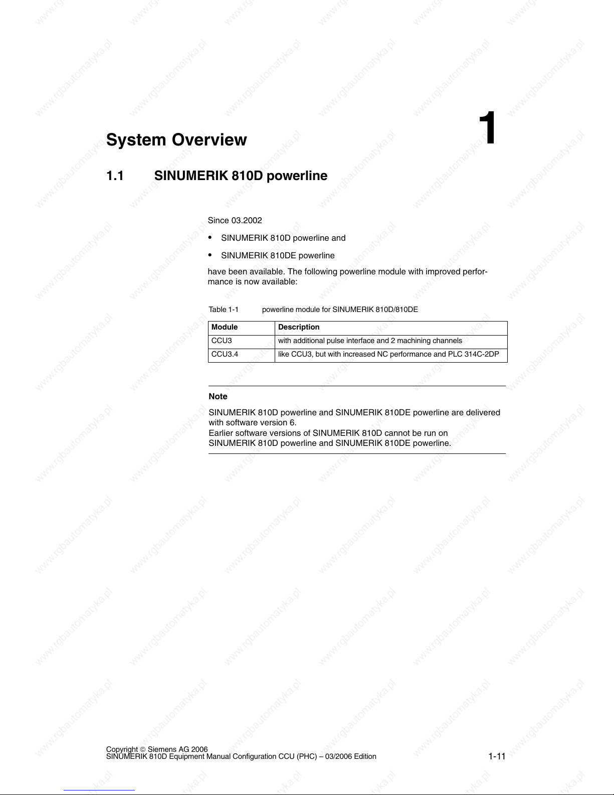
Since 03.2002
SINUMERIK 810D powerline and
SINUMERIK 810DE powerline
have been available. The following powerline module with improved perfor-
mance is now available:
Table 1-1 powerline module for SINUMERIK 810D/810DE
Module
Description
CCU3 with additional pulse interface and 2 machining channels
CCU3.4 like CCU3, but with increased NC performance and PLC 314C-2DP
Note
SINUMERIK 810D powerline and SINUMERIK 810DE powerline are delivered
with software version 6.
Earlier software versions of SINUMERIK 810D cannot be run on
SINUMERIK 810D powerline and SINUMERIK 810DE powerline.
1
1.2 System configuration
1-12
Copyright © Siemens AG 2006
SINUMERIK 810D Equipment Manual Configuration CCU (PHC) – 03/2006 Edition
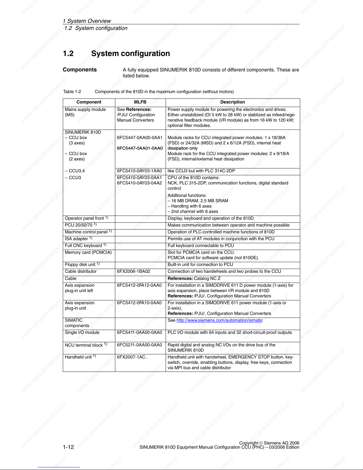
1.2 System configuration
A fully equipped SINUMERIK 810D consists of different components. These are
listed below.
Table 1-2 Components of the 810D in the maximum configuration (without motors)
Component
MLFB Description
Mains supply module
(MS)
See References:
/PJU/ Configuration
Manual Converters
Power supply module for powering the electronics and drives.
Either unstabilized (OI 5 kW to 28 kW) or stablized as infeed/rege-
nerative feedback module (I/R module) as from 16 kW to 120 kW;
optional filter modules.
SINUMERIK 810D
– CCU box
(3 axes)
6FC5447-0AA00-0AA1
Module racks for CCU integrated power modules: 1 x 18/36A
(FSD) or 24/32A (MSD) and 2 x 6/12A (FSD), internal heat
– CCU box
(2 axes)
6FC5447-0AA01-0AA0
dissi
pation only
Module rack for the CCU integrated power modules: 2 x 9/18/A
(FSD), internal/external heat dissipation
– CCU3.4 6FC5410-0AY03-1AA0 like CCU3 but with PLC 314C-2DP
– CCU3 6FC5410-0AY03-0AA1
6FC5410-0AY03-0AA2
CPU of the 810D contains:
NCK, PLC 315-2DP, communication functions, digital standard
control
Additional functions:
– 16 MB DRAM, 2.5 MB SRAM
– Handling with 6 axes
– 2nd channel with 6 axes
Operator panel front
1)
Display, keyboard and operation of the 810D
PCU 20/50/70
1)
Makes communication between operator and machine possible
Machine control panel
1)
Operation of PLC-controlled machine functions of 810D
ISA adapter
1)
Permits use of AT modules in conjunction with the PCU
Full CNC keyboard
1)
Full keyboard connectable to PCU
Memory card (PCMCIA) Slot for PCMCIA card on the CCU.
PCMCIA card for software update (not 810DE).
Floppy disk unit
1)
Built-in unit for connection to PCU
Cable distributor 6FX2006-1BA02 Connection of two handwheels and two probes to the CCU
Cable References: Catalog NC Z
Axis expansion
plug-in unit left
6FC5412-0FA12-0AA0 For installation in a SIMODRIVE 611 D power module (1-axis) for
axis expansion, place between I/R module and 810D
References: /PJU/, Configuration Manual Converters
Axis expansion
plug-in unit
6FC5412-0FA10-0AA0 For installation in a SIMODRIVE 611 power module (1-axis or
2-axis),
References: /PJU/, Configuration Manual Converters
SIMATIC
components
See http://www.siemens.com/automation/simatic
Single I/O module 6FC5411-0AA00-0AA0 PLC I/O module with 64 inputs and 32 short-circuit-proof outputs
NCU terminal block
1)
6FC5211-0AA00-0AA0 Rapid digital and analog NC I/Os on the drive bus of the
SINUMERIK 810D
Handheld unit
1)
6FX2007-1AC.. Handheld unit with handwheel, EMERGENCY STOP button, key-
switch, override, enabling buttons, display, free keys, connection
via MPI bus and cable distributor
Components
1 S
y
stem Overview

1.2 System configuration
1-13
Copyright © Siemens AG 2006
SINUMERIK 810D Equipment Manual Configuration CCU (PHC) – 03/2006 Edition
Component DescriptionMLFB
Handheld terminal
(HT 6)
1)
6FC5403-0AA10-0AA0 Handheld unit combining the functions of operator panel front and
MCP, with
– Display,
– Keyboard, enabling buttons, EMERGENCY STOP and override
button
– RS 232 C interface for archiving programs and data
– Connection via cables and distributors to SINUMERIK
810D/840Di/840D and FM357-2H
Distributor box
1)
6FX2006-1BC00 For linking the hand-held unit to the MPI bus. Connection for
EMERGENCY STOP circuit, enable keys, handwheel, 24 V DC
Mini Handheld Unit
1)
6FX2006-1BG00 Small handheld unit for setup and operation on simple machines
for job shop or similar applications.
Use with 810D, 840C, 840D, and FM-NC possible.
The components marked with 1) are described in:
References: /BH/, Operator Components Manual
1 System Overview

1.2 System configuration
1-14
Copyright © Siemens AG 2006
SINUMERIK 810D Equipment Manual Configuration CCU (PHC) – 03/2006 Edition
MCP
Diskette
unit
Operator panel front
Axis
expansion
plug-in
unit
I/R
FSD FSD
Handwheel (2x)
Measurement (2x) *)
Cable
distributor
Single
I/O module
810D
2x
Motor encoder
cable
Terminal block
Motors
e.g. 1FNx, 1FEx, 1FKx
Distributor box
Motor cable
QWERTY
keyboard
5x
OI
or
2x
1x
PCU
MPI
cable
SIMATIC
IM cable
611
power
module
Encoder cable
direct
measuring system
Direct measuring
system
(e.g. on the X416)
SIMATIC
Profibus I/O
Handheld
unit
Handheld unit or mini handheld unit or HT 6
14
15
14
*) One measurement input can be replaced by a 3rd handwheel
HT 6
16
17
(CCU3)
Axis
expansion
plug-in
unit
1x
MSD
* TEMP
* POWER
SINUMERIK
Fig. 1-1 System of the SINUMERIK 810D, for example, the CCU3
1 System Overview
1.2 System configuration
1-15
Copyright © Siemens AG 2006
SINUMERIK 810D Equipment Manual Configuration CCU (PHC) – 03/2006 Edition
17
X3
Floppy/interface
MCP
PG740 programming device
Cable distributor
QWERTY
MPI bus cable
MPI cable
X20
(Rear view)
Distributor box
HHU
Handwheel HHU
X4
X1
X2
X5
CCU 3
MPI bus cable
2
3
4
1
5
6
Handwheel
Measuring probe
Shield
or
HT 6
16
PCU50
(right side of
housing)
PC card
Connection on left side of housing
PS/2 mouse
COM1/RS232/PLC
LPT1/PRINTER
VGA
24V power supply
USB
COM2
Ethernet
PCI slot PCI/ISA slot
MPI/DP
2
–X307
–X122
–X102
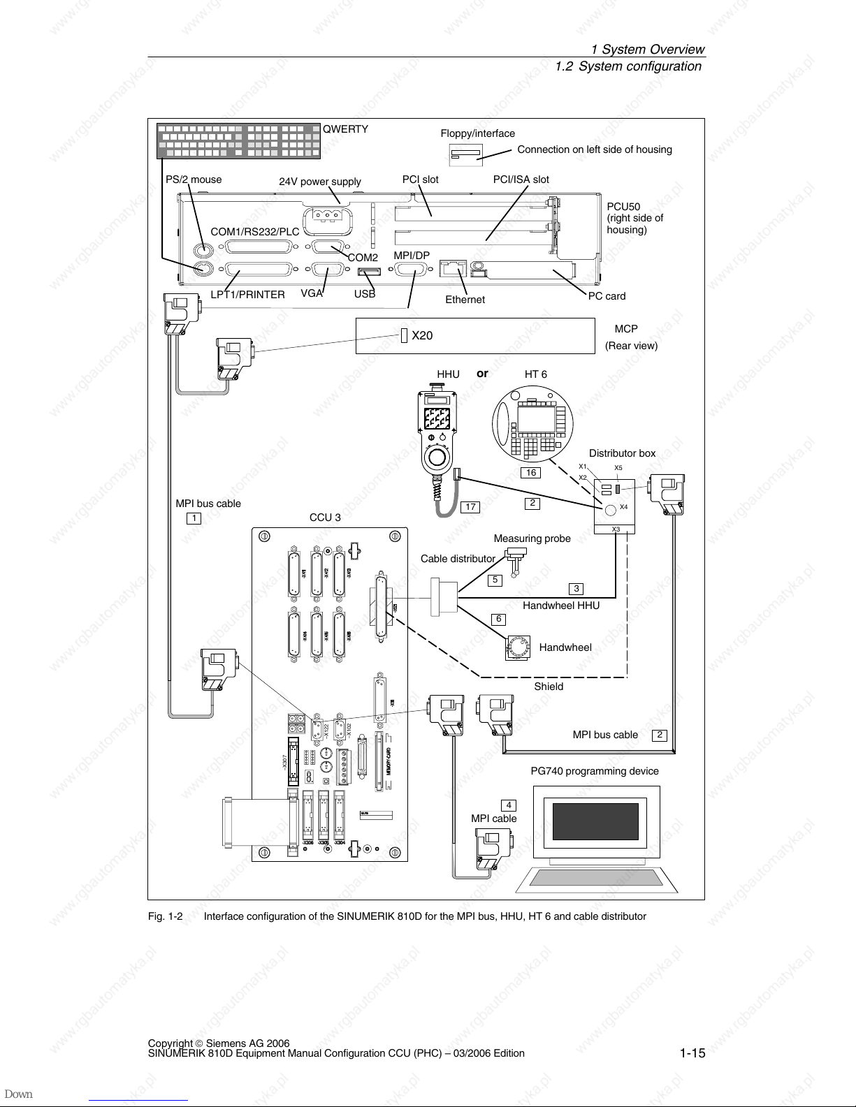
Fig. 1-2 Interface configuration of the SINUMERIK 810D for the MPI bus, HHU, HT 6 and cable distributor
1 System Overview
1.2 System configuration
1-16
Copyright © Siemens AG 2006
SINUMERIK 810D Equipment Manual Configuration CCU (PHC) – 03/2006 Edition
CCU3
IM
SIMATIC S7-300 I/O
PS SMs
X2
SIMATIC S7-300 IM connecting cable
Connecting cable shielded
Single I/O module
Terminal block
Drive bus cable
Pay attention to maximum configuration !!
1)
1)
Terminator
Single I/O module Single I/O module
–X307
–X130
8
8
8
7 9
–X411
–X412
–X413–X416
–X415
–X414
–X121
–X111
–X122
–X102
–X431
MEMORY CARD
–X306
–X305 –X304
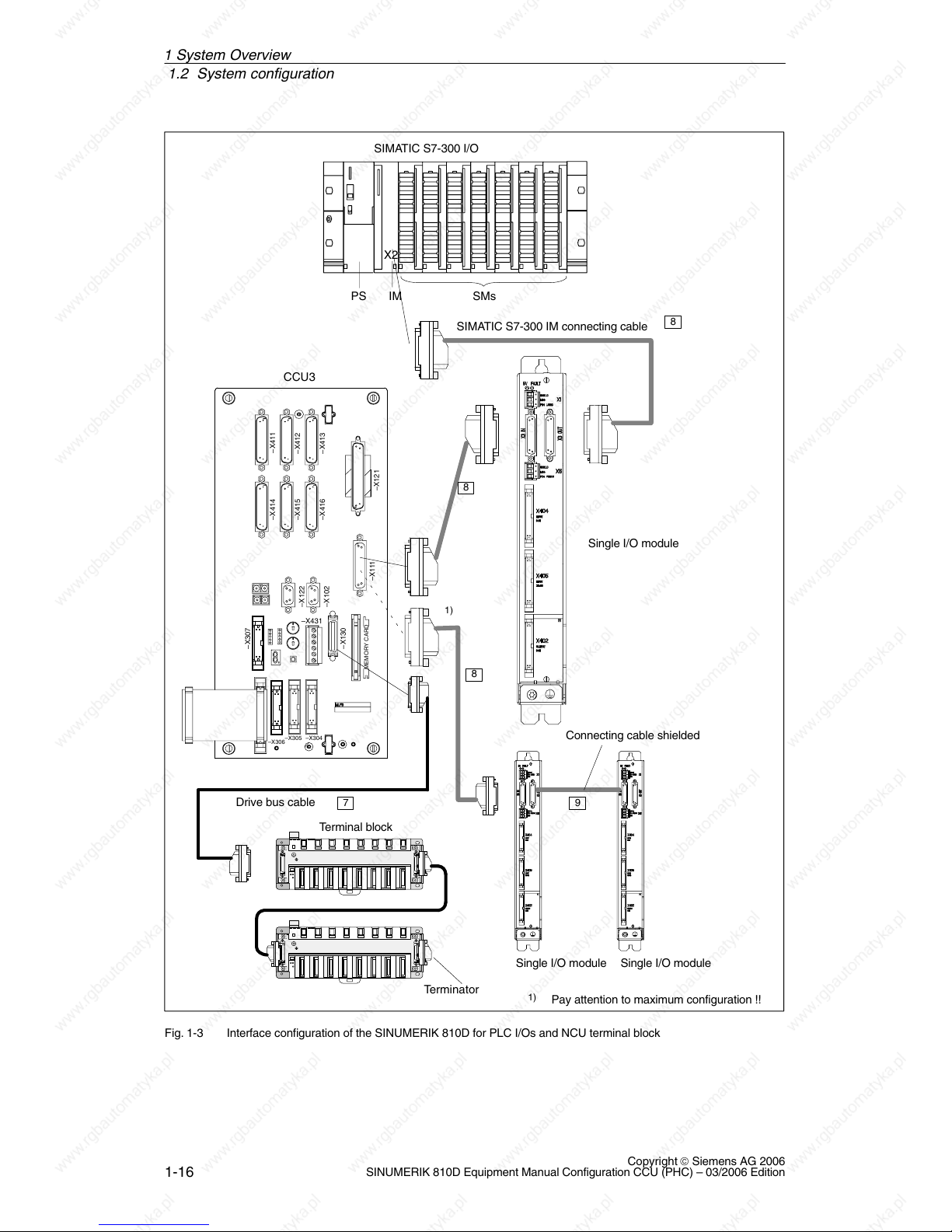
Fig. 1-3 Interface configuration of the SINUMERIK 810D for PLC I/Os and NCU terminal block
1 System Overview
1.2 System configuration
1-17
Copyright © Siemens AG 2006
SINUMERIK 810D Equipment Manual Configuration CCU (PHC) – 03/2006 Edition
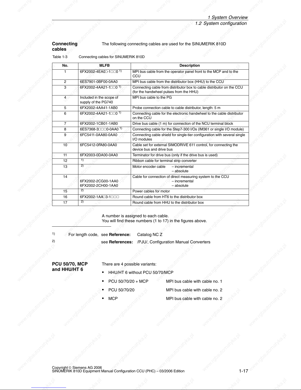
The following connecting cables are used for the SINUMERIK 810D
Table 1-3 Connecting cables for SINUMERIK 810D
No.
MLFB Description
1 6FX2002-4EA0-10
1)
MPI bus cable from the operator panel front to the MCP and to the
CCU
2 6ES7901-0BF00-0AA0 MPI bus cable from the distributor box (HHU) to the CCU
3 6FX2002-4AA21-10
1)
Connecting cable from distributor box to cable distributor on the CCU
(for the handwheel pulses from the HHU)
4 Included in the scope of
supply of the PG740
MPI bus cable to the PG
5 6FX2002-4AA41-1AB0 Probe connection cable to cable distributor, length: 5 m
6 6FX2002-4AA21-10
1)
Connecting cable for the electronic handwheel to the cable distributor
on the CCU
7 6FX2002-1CB01-1AB0 Drive bus cable (1 m) for connection of the NCU terminal block
8 6ES7368-30-0AA0
1)
Connecting cable for the Step7-300 I/Os (IM361 or single I/O module)
9 6FC5411-0AA80-0AA0 Connecting cable shield for single-tier configuration with several single
I/O modules
10 6FC5412-0FA80-0AA0 Cable set for external SIMODRIVE 611 control, for connecting the
device bus and drive bus
11 6FX2003-0DA00-0AA0 Terminator for drive bus (only if the drive bus is used)
12
1)
Ribbon cable for terminal strip converter
13
2)
Motor encoder cable – incremental
– absolute
14
6FX2002-2CG00-1AA0
6FX2002-2CH00-1AA0
Cable for connection of direct measuring system to the CCU
– incremental
– absolute
15
2)
Power cables for motor
16 6FX2002-1AA3-1 Round cable from HT6 to the distributor box
17
2)
Round cable from HHU to the distributor box
A number is assigned to each cable.
You will find these numbers (1 to 17) in the figures above.
1)
For length code, see Reference: Catalog NC Z
2)
see References: /PJU/, Configuration Manual Converters
There are 4 possible variants:
HHU/HT 6 without PCU 50/70/MCP
PCU 50/70/20 + MCP MPI bus cable with cable no. 1
PCU 50/70/20 MPI bus cable with cable no. 2
MCP MPI bus cable with cable no. 2
Connecting
cables
PCU 50/70, MCP
and HHU/HT 6
1 S
y
stem Overview
1.2 System configuration
1-18
Copyright © Siemens AG 2006
SINUMERIK 810D Equipment Manual Configuration CCU (PHC) – 03/2006 Edition
On the SINUMERIK 810D, the number of axes can be expanded to six axes,
including spindles.
There are two possibilities:
either Connect axis expansion plug-in unit and SIMODRIVE 611 power
module at axis expansion interface,
or Connect SIMODRIVE 611D control plug-in unit with SIMODRIVE 611
power module on drive bus/device bus.
The axis expansion plug-in units are used whenever no more than six measur-
ing channels are required for the SINUMERIK 810D. This plug-in unit is plugged
into a SIMODRIVE 611 power module. The axis expansion plug-in units are
designed for 1-axis and 2-axis power modules. The ribbon cables are part of the
plug-in unit.
If the six measuring channels of the SINUMERIK 810D are insufficient,
SIMODRIVE 611 controller plug-ins must be inserted into the SIMODRIVE 611
power modules to connect further measuring systems (connection via drive bus
with drive bus terminator). If 611D control modules are used, it may be neces-
sary to connect the NCU terminal block to the free drive bus connector of the
611D control.
See Chapter 5, Axis expansion
The CCU can control up to 6 axes onboard. For this purpose there is a new
expansion plug-in in addition to the existing axis expansion plug-in modules.
All power modules of the 611D series can be connected as external power
modules for axis expansion.
As from SW 6.3, the limitation to six drives applies.
Expansion levels 1 to 6 can be achieved by many combinations. To operate the
spindle to the internal power module, connect it to the 24A/32A power module
(A1).
Axis expansion on
810D
Axis expansion
plug-in unit
Axis expansion
control
plug-in unit
Power modules
Combinations
1 S
y
stem Overview
1.2 System configuration
1-19
Copyright © Siemens AG 2006
SINUMERIK 810D Equipment Manual Configuration CCU (PHC) – 03/2006 Edition
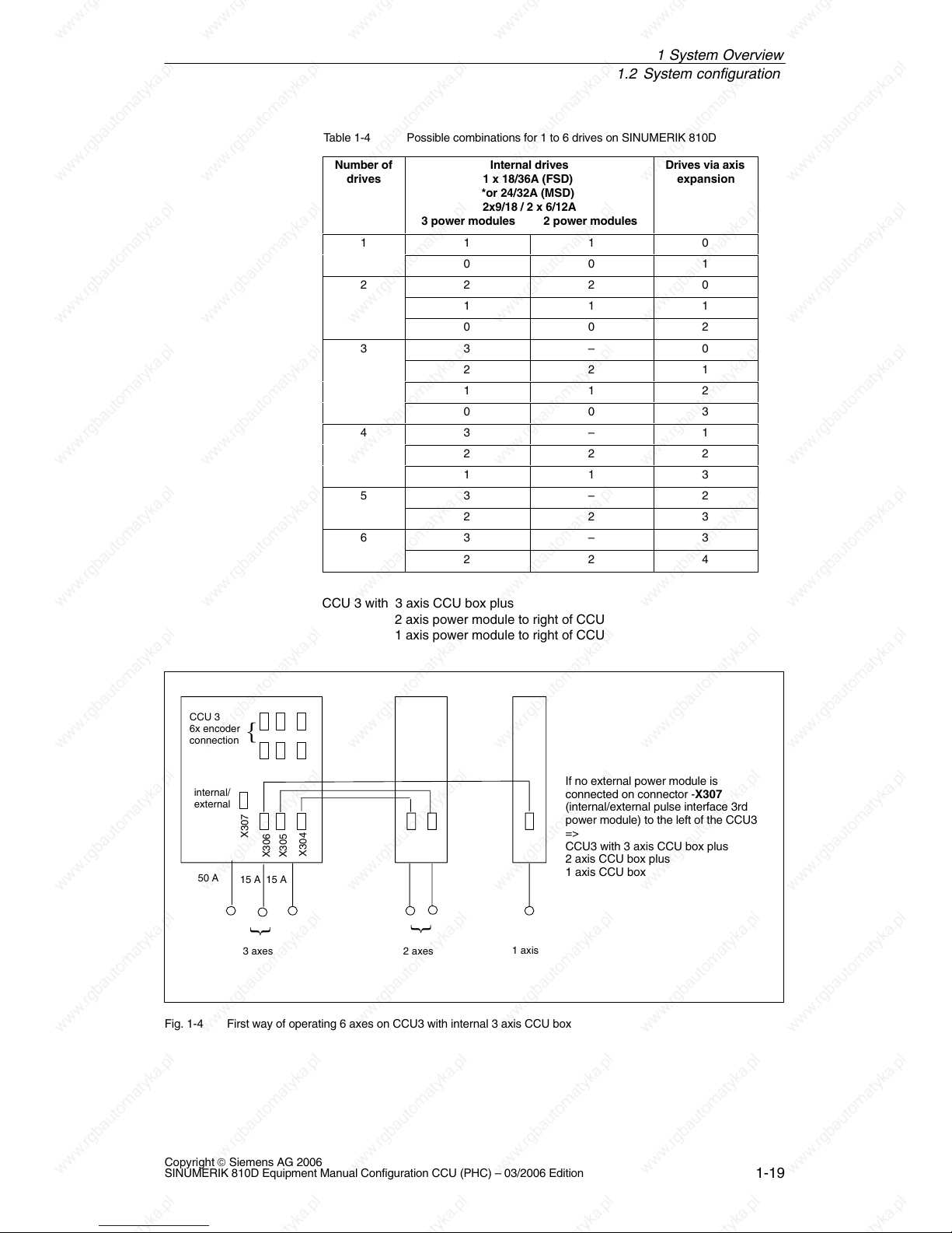
Table 1-4 Possible combinations for 1 to 6 drives on SINUMERIK 810D
Number of
drives
Internal drives
1 x 18/36A (FSD)
*or 24/32A (MSD)
2x9/18 / 2 x 6/12A
3 power modules 2 power modules
Drives via axis
expansion
1 1 1 0
0 0 1
2 2 2 0
1 1 1
0 0 2
3 3 – 0
2 2 1
1 1 2
0 0 3
4 3 – 1
2 2 2
1 1 3
5 3 – 2
2 2 3
6 3 – 3
2 2 4
CCU 3 with 3 axis CCU box plus
2 axis power module to right of CCU
1 axis power module to right of CCU
CCU 3
6x encoder
connection
internal/
external
X307
50 A
15 A 15 A
3 axes 2 axes
1 axis
{
{
{
If no external power module is
connected on connector -X307
(internal/external pulse interface 3rd
power module) to the left of the CCU3
=>
CCU3 with 3 axis CCU box plus
2 axis CCU box plus
1 axis CCU box
X306
X305
X304
Fig. 1-4 First way of operating 6 axes on CCU3 with internal 3 axis CCU box
1 System Overview
1.2 System configuration
1-20
Copyright © Siemens AG 2006
SINUMERIK 810D Equipment Manual Configuration CCU (PHC) – 03/2006 Edition
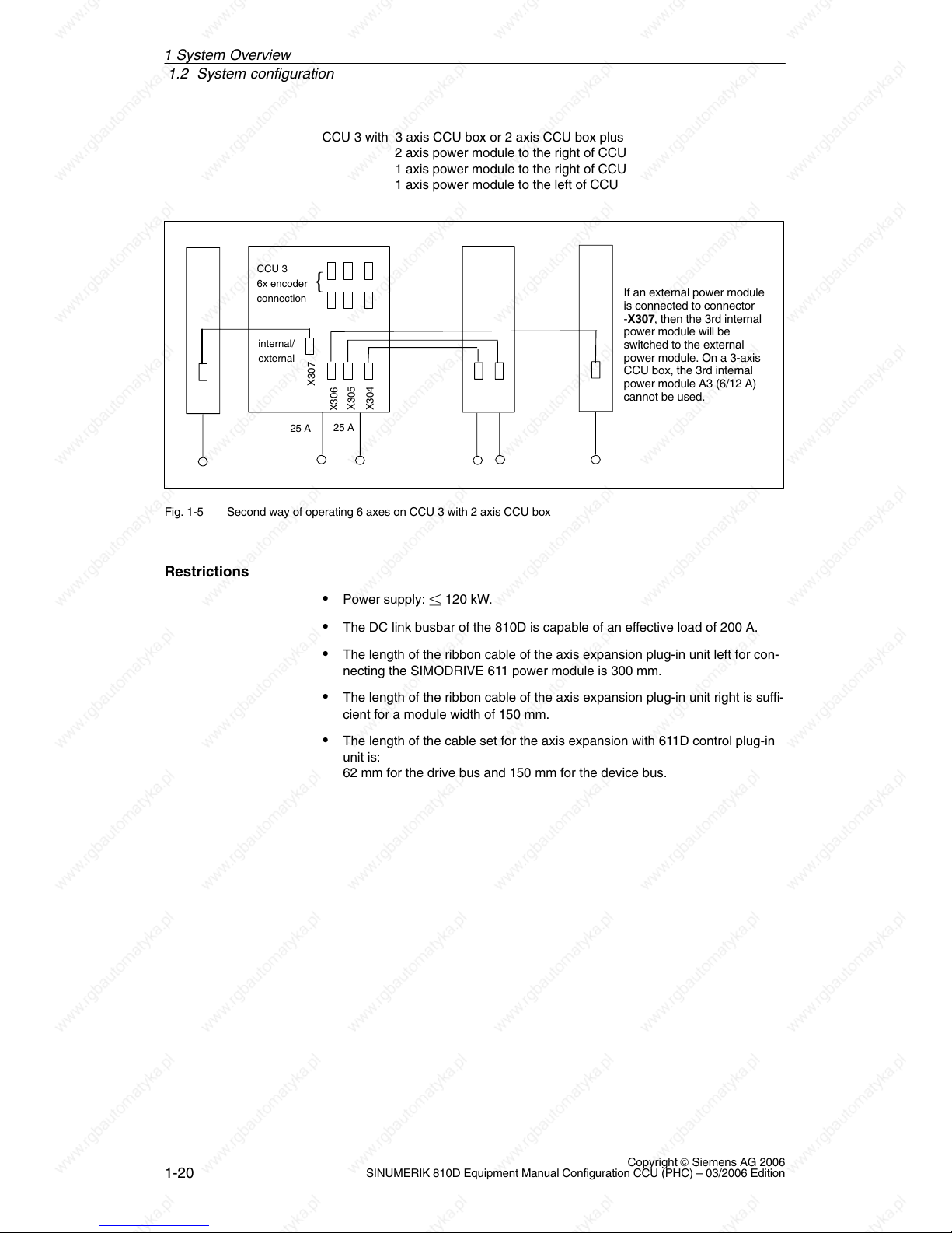
CCU 3 with 3 axis CCU box or 2 axis CCU box plus
2 axis power module to the right of CCU
1 axis power module to the right of CCU
1 axis power module to the left of CCU
CCU 3
6x encoder
connection
internal/
external
X304
25 A
25 A
{
If an external power module
is connected to connector
-X307, then the 3rd internal
power module will be
switched to the external
power module. On a 3-axis
CCU box, the 3rd internal
power module A3 (6/12 A)
cannot be used.
X305
X306
X307
Fig. 1-5 Second way of operating 6 axes on CCU 3 with 2 axis CCU box
Power supply: 120 kW.
The DC link busbar of the 810D is capable of an effective load of 200 A.
The length of the ribbon cable of the axis expansion plug-in unit left for con-
necting the SIMODRIVE 611 power module is 300 mm.
The length of the ribbon cable of the axis expansion plug-in unit right is suffi-
cient for a module width of 150 mm.
The length of the cable set for the axis expansion with 611D control plug-in
unit is:
62 mm for the drive bus and 150 mm for the device bus.
Restrictions
1 S
y
stem Overview
1.3 Labels
1-21
Copyright © Siemens AG 2006
SINUMERIK 810D Equipment Manual Configuration CCU (PHC) – 03/2006 Edition
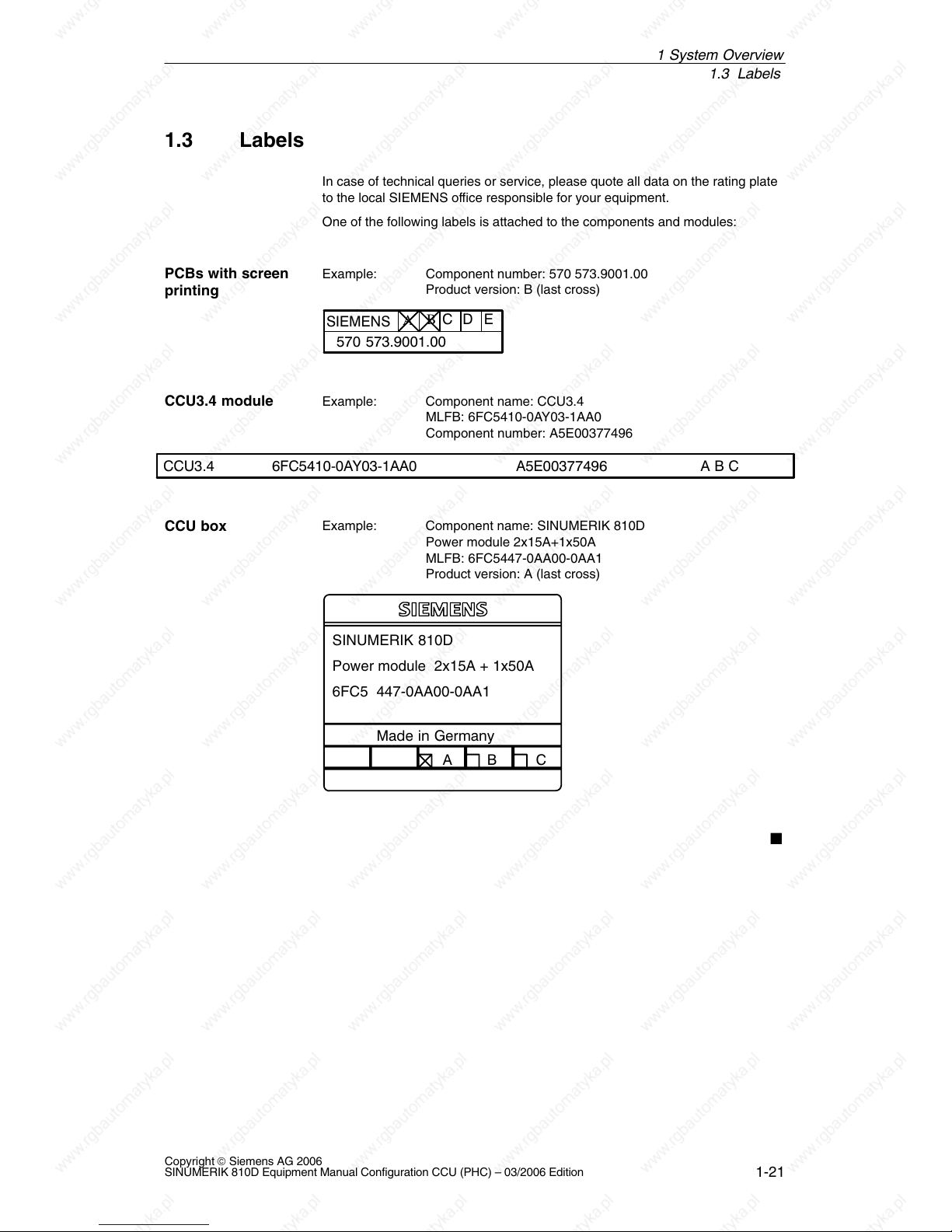
1.3 Labels
In case of technical queries or service, please quote all data on the rating plate
to the local SIEMENS office responsible for your equipment.
One of the following labels is attached to the components and modules:
Example: Component number: 570 573.9001.00
Product version: B (last cross)
570 573.9001.00
E
D
C
SIEMENS
A
B
Example: Component name: CCU3.4
MLFB: 6FC5410-0AY03-1AA0
Component number: A5E00377496
A B CA5E003774966FC5410Ć0AY03Ć1AA0CCU3.4
Example: Component name: SINUMERIK 810D
Power module 2x15A+1x50A
MLFB: 6FC5447-0AA00-0AA1
Product version: A (last cross)
SINUMERIK 810D
Power module 2x15A + 1x50A
6FC5 447-0AA00-0AA1
CBA
Made in Germany
PCBs with screen
printing
CCU3.4 module
CCU box
1 S
y
stem Overview

1.3 Labels
1-22
Copyright © Siemens AG 2006
SINUMERIK 810D Equipment Manual Configuration CCU (PHC) – 03/2006 Edition
1 System Overview
Notes
2-23
Copyright © Siemens AG 2006
SINUMERIK 810D Equipment Manual Configuration CCU (PHC) – 03/2006 Edition
Connection Conditions
2.1 Supplementary electrical conditions
The controller is tested for compliance with the ambient conditions specified
below. Fault-free operation is only ensured if:
These environmental conditions are maintained when storing, transporting
and operating the equipment.
Original components and spare parts are used. This applies in particular to
the use of specified cables and plug connectors.
The equipment has been correctly mounted/installed.
!
Danger
The equipment may not be commissioned until it has been clearly identified
that the machine in which the controller is installed is in full conformance with
the specifications in EC Machinery Directive 98/37/EC.
The connection conditions must be carefully maintained for the complete
system. Please contact your local Siemens office or representative for any
assistance.
Compliance with
the connection
conditions
Assistance and
support
2

2.1 Supplementary electrical conditions
2-24
Copyright © Siemens AG 2006
SINUMERIK 810D Equipment Manual Configuration CCU (PHC) – 03/2006 Edition
2.1.1 Power supply
!
Warning
The DC power supply is always referenced to ground and must be
generated by a safety transformer.
Final user interfaces are powered via a DC power supply with protective
separation per EN 61800-5-1.
In the case of supply cables > 10 m, protective elements must be fitted at
the device input in order to protect against lightning (surge voltage).
The DC power supply must be connected to the ground/shield of the NC for
EMC and/or functional reasons. For EMC reasons, this connection should
only be made at one point. As a rule, the connection is provided as
standard in the S7-300 I/Os. If this is not the case in exceptional circum-
stances, the ground connection should be made to the grounding rail of the
NC cabinet; also refer to /EMC/ EMC Configuring Guidelines.
Table 2-1 Requirements of the DC supply
Rated voltage
In accordance with EN 61131-2
Voltage range (average value)
Voltage ripple peak-to-peak
Ramp-up time at power-on
24 V DC
20.4 V DC to 28.8 V DC
5 % (unfiltered 6-pulse rectification)
Any
Non-cyclic overvoltages
Duration
Restoration time
Events per hour
35 V
500 ms
50 s
10
Transient voltage interruptions
Outage time
Restoration time
Events per hour
3 ms
10 s
10
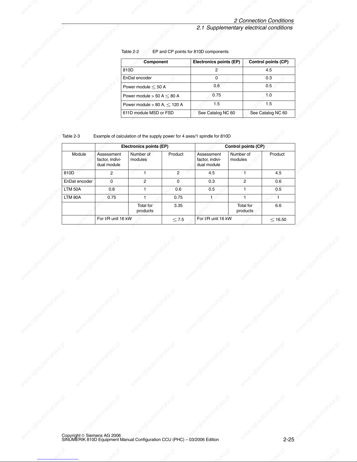
The EP and CP points for the power modules only apply in conjunction with the
SINUMERIK 810D (axis expansion). The EP and CP points from Catalog NC 60
apply when SIMODRIVE 611D modules with control plug-in units are used.
Demands on DC
power supplies
Configuration
810D power
consumption
2
Connection Conditions
2.1 Supplementary electrical conditions
2-25
Copyright © Siemens AG 2006
SINUMERIK 810D Equipment Manual Configuration CCU (PHC) – 03/2006 Edition
Table 2-2 EP and CP points for 810D components
Component
Electronics points (EP) Control points (CP)
810D 2 4.5
EnDat encoder 0 0.3
Power module 50 A
0.6 0.5
Power module > 50 A 80 A
0.75 1.0
Power module > 80 A, 120 A
1.5 1.5
611D module MSD or FSD See Catalog NC 60 See Catalog NC 60
Table 2-3 Example of calculation of the supply power for 4 axes/1 spindle for 810D
Electronics points (EP) Control points (CP)
Module Assessment
factor, indivi-
dual module
Number of
modules
Product Assessment
factor, indivi-
dual module
Number of
modules
Product
810D
2
1 2 4.5 1 4.5
EnDat encoder 0 2 0 0.3 2 0.6
LTM 50A 0.6 1 0.6 0.5 1 0.5
LTM 80A 0.75 1 0.75 1 1 1
Total for
products
3.35 Total for
products
6.6
For I/R unit 16 kW
7.5
For I/R unit 16 kW
16.50
2
Connection Conditions
2.1 Supplementary electrical conditions
2-26
Copyright © Siemens AG 2006
SINUMERIK 810D Equipment Manual Configuration CCU (PHC) – 03/2006 Edition
2.1.2 Safe isolation to EN 61800-5-1
The complete system includes end user interfaces (UIs) and interfaces for
servicing, commissioning and maintenance.
UIs are all the interfaces that are freely accessible to the machine operator
without the need for tools or aids. These user interfaces are designed with safe
isolation to EN 61800-5-1.
!
Danger
The interfaces for servicing, commissioning and maintenance purposes are
provided without safe isolation.
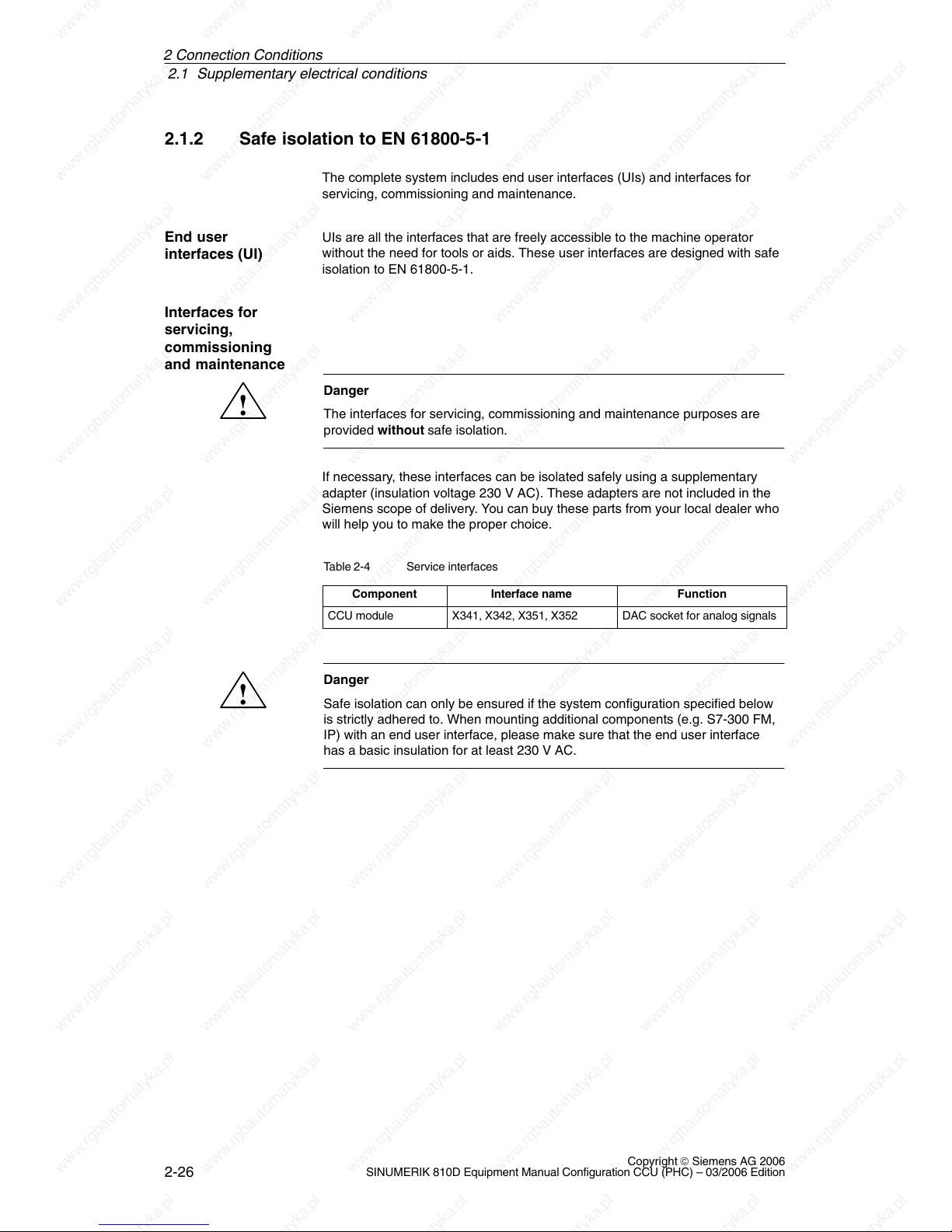
If necessary, these interfaces can be isolated safely using a supplementary
adapter (insulation voltage 230 V AC). These adapters are not included in the
Siemens scope of delivery. You can buy these parts from your local dealer who
will help you to make the proper choice.
Table 2-4 Service interfaces
Component
Interface name Function
CCU module X341, X342, X351, X352 DAC socket for analog signals
!
Danger
Safe isolation can only be ensured if the system configuration specified below
is strictly adhered to. When mounting additional components (e.g. S7-300 FM,
IP) with an end user interface, please make sure that the end user interface
has a basic insulation for at least 230 V AC.
End user
interfaces (UI)
Interfaces for
servicing,
commissioning
and maintenance
2
Connection Conditions
2.1 Supplementary electrical conditions
2-27
Copyright © Siemens AG 2006
SINUMERIK 810D Equipment Manual Configuration CCU (PHC) – 03/2006 Edition
Basic insulation Protective separation
M (GND)
3 x 400 V AC
N
Housing/shield
810D/611 digital
1
2
3
4
10
4
4
5
6
11
S7-300 I/Os
MSTT/MCP
PCU
9
24V
8
Person
M (GND)
7
10
11
11
Machine
5
4
Distributor box
HHU/
HT 6
Terminal
block
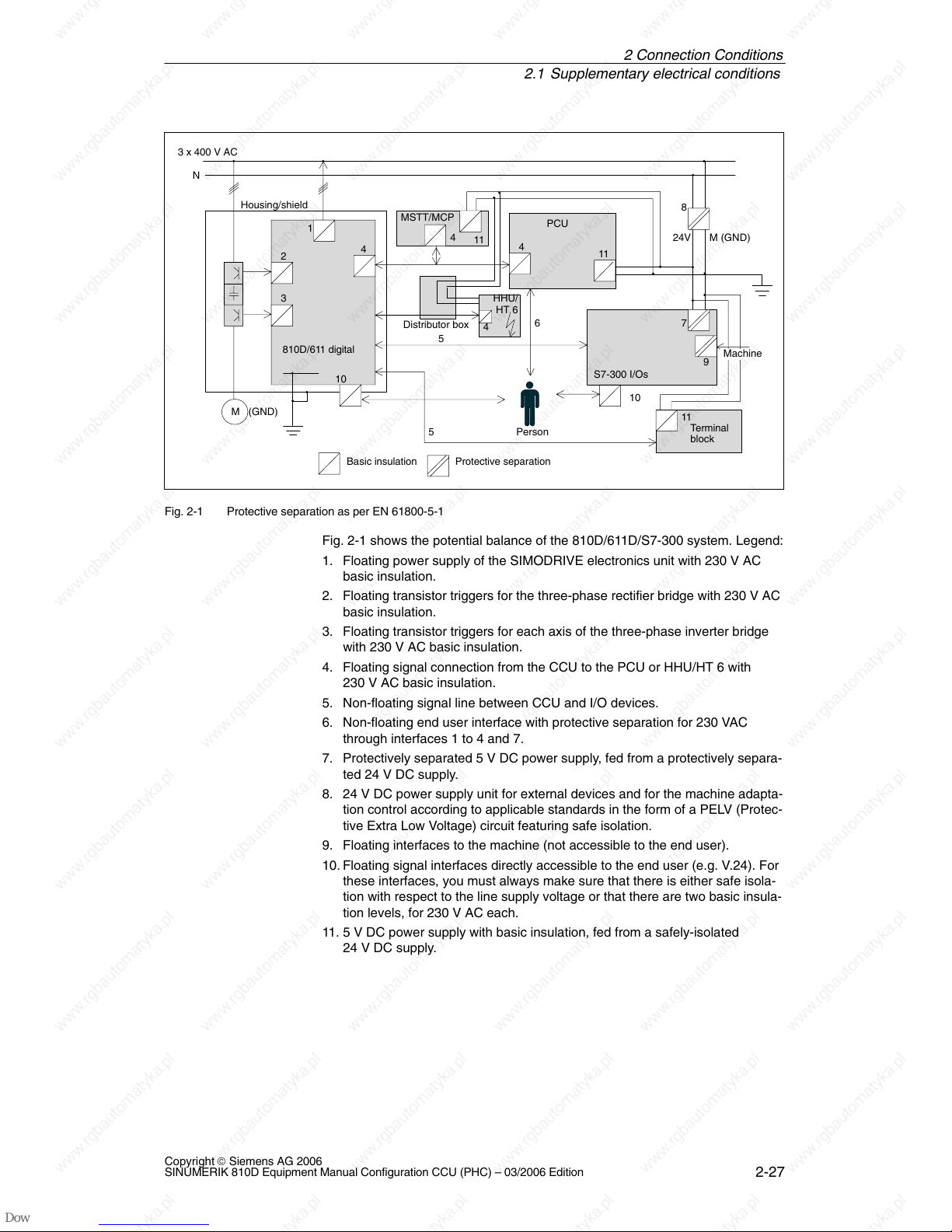
Fig. 2-1 Protective separation as per EN 61800-5-1
Fig. 2-1 shows the potential balance of the 810D/611D/S7-300 system. Legend:
1. Floating power supply of the SIMODRIVE electronics unit with 230 V AC
basic insulation.
2. Floating transistor triggers for the three-phase rectifier bridge with 230 V AC
basic insulation.
3. Floating transistor triggers for each axis of the three-phase inverter bridge
with 230 V AC basic insulation.
4. Floating signal connection from the CCU to the PCU or HHU/HT 6 with
230 V AC basic insulation.
5. Non-floating signal line between CCU and I/O devices.
6. Non-floating end user interface with protective separation for 230 VAC
through interfaces 1 to 4 and 7.
7. Protectively separated 5 V DC power supply, fed from a protectively separa-
ted 24 V DC supply.
8. 24 V DC power supply unit for external devices and for the machine adapta-
tion control according to applicable standards in the form of a PELV (Protec-
tive Extra Low Voltage) circuit featuring safe isolation.
9. Floating interfaces to the machine (not accessible to the end user).
10. Floating signal interfaces directly accessible to the end user (e.g. V.24). For
these interfaces, you must always make sure that there is either safe isola-
tion with respect to the line supply voltage or that there are two basic insula-
tion levels, for 230 V AC each.
11. 5 V DC power supply with basic insulation, fed from a safely-isolated
24 V DC supply.
2
Connection Conditions
2.1 Supplementary electrical conditions
2-28
Copyright © Siemens AG 2006
SINUMERIK 810D Equipment Manual Configuration CCU (PHC) – 03/2006 Edition
2.1.3 Grounding Concept
The SINUMERIK 810D system consists of a number of individual components,
each of which must comply with the appropriate EMC and safety standards. The
individual system components are:
CCU box
Machine control panel MCP
Keyboard
Operator panels (operator panel front + PCU/TCU)
NCU terminal block
Distributor box and handheld unit
S7-300 I/O with IM 361 interface module
Single I/O module
CCU box and SIMODRIVE components are fixed to a metal cabinet plate with
screws. Make sure that near the screws a low-impedance contact of the CCU
box with the cabinet panel can be made. Insulating varnishes must be removed
where possible. The connection must be kept free of corrosion.
The electronics grounds of the modules are interconnected via the unit and con-
trol bus and also routed to terminal X151 of the NE module.
The ground and module ground M should be connected at the power supply
terminal of the IM 361. Further, for the EFP, “SHIELD” and “M24” must be con-
nected in connector X1.
2
Connection Conditions
 Loading...