

Siemens 599 Series, SFP71U, SF Series, SFP277U/25, SFP11U Installation Instructions Manual
...
599 Series Zone Valves
SFA/SFP Electronic Valve Actuator
2-Position Control
Installation Instructions
Document No. 129-335
June 22, 2005
Product Description
The SF Series actuator requires a 24 Vac, 120 Vac, 208 Vac,
or 277 Vac Class-2 supply signal to control Siemens Zone
Valves with a 1/10-inch (2.5 mm) stroke.
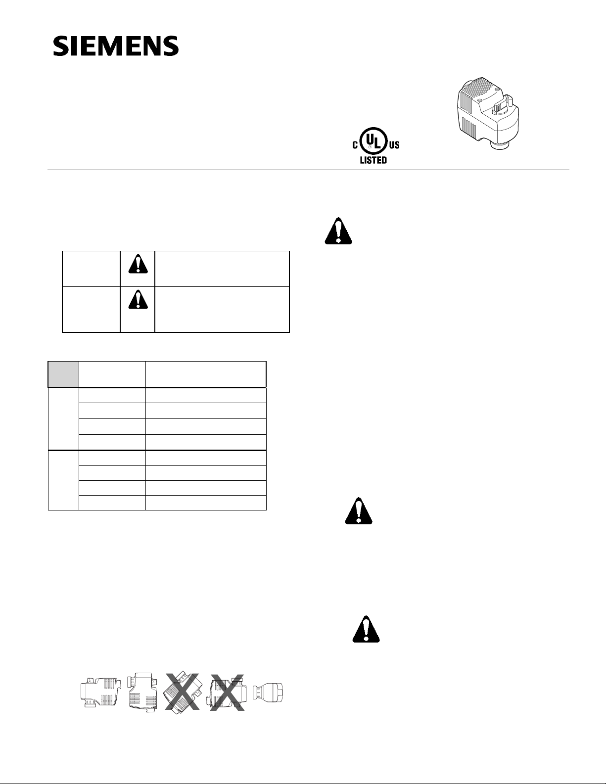
Warning/Caution Notations
WARNING:
CAUTION:
Personal injury or loss of life
may occur if you do not follow
a procedure as specified.
Equipment damage, or loss of
data may occur if you do not
follow a procedure as
specified.
Product Numbers
Actuator
Model
SFP71U 24 Vac 243
SFP11U 120 Vac 241
SFP277U/25 277 Vac – *
Open
Normally
SFP208U/25 208 Vac – *
SFA71U 24 Vac 242
SFA11U 120 Vac 240
SFA208U/25 208 Vac – *
Closed
Normally
SFA277U/25 277 Vac – *
Power
Supply
* Actuator only with 2.5-meter cable, not available
as an assembly.
Actuator
Code
Contents
One actuator
EA0961R1
The vertical position is recommended for mounting.
Prerequisites
WARNING:
1. If mounting the actuator to a valve already
2. Disconnect the controller power before
Installation
Mounting the SFP Actuator to a Valve
1. Place the actuator on the valve and firmly hand-tighten the
coupling piece.
2. Connect the wires. See Wiring.
Mounting the SFA Actuator on a Valve
1. Rotate the manual override lever and latch.
in line:
• Close the shut-off valves in the piping
(upstream first, then downstream).
Or
• Switch off the pump to allow the
differential pressure in the valve to
drop.
replacing the actuator.
CAUTION:
The black actuator attachment support ring
must be in place on top of the valve bonnet
before installing the actuator.
If the support ring is not in place, damage to
the actuator connection may result.
Required Tools
• Small flat-blade screwdriver
• Wire stripper
Estimated Installation Time
20 minutes
EA0959R1
Figure 1. Acceptable Mounting Positions.
Item Number 129-335, Rev. 015 Page 1 of 4
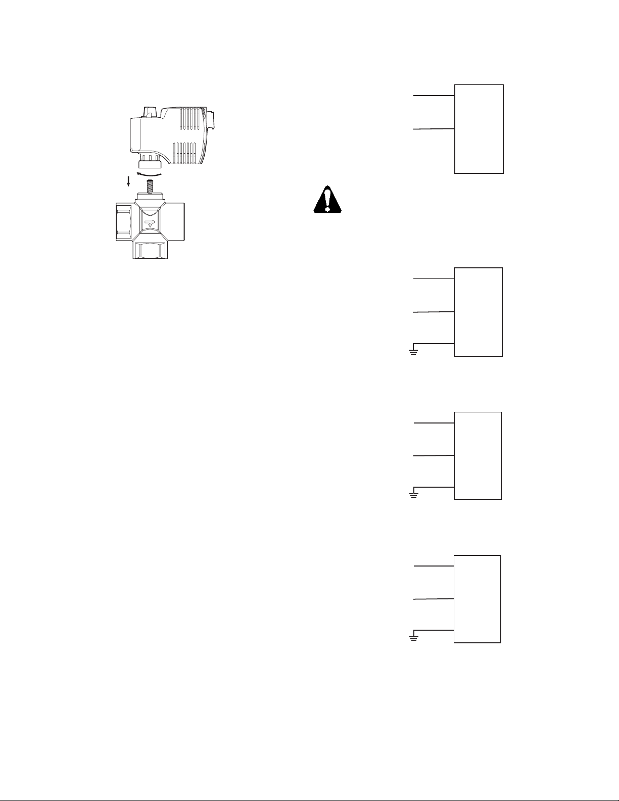
2. Place the actuator on the valve and firmly hand-tighten
the coupling piece.
CAUTION:
Failure to fully rotate the manual override
handle before hand tightening will hinder
proper valve close off.
3. Release manual override handle.
4. Connect the wires. See Wiring.
Document No.129-335
Installation Instructions
June 22, 2005
1
VE0268R1
2
Figure 2. Mounting the Actuator on a Valve.
The installation is now complete.
Removing the Actuator from a Valve
1. Disconnect the wiring.
2. Unscrew actuator-coupling piece from the valve body
threads.
3. Remove the actuator from the valve.
Wiring
• All wiring must conform to NEC and local codes and
regulations.
• Use earth ground isolating step-down Class 2
transformers.
NOTE: Do not use autotransformers.
• Determine the supply transformer rating by summing
the total VA of all actuators used. The maximum
rating for a Class 2 step-down transformer is 100 VA.
NOTE: It is recommended that one transformer power
no more than 10 actuators.
• SFA71U/SFP71U 24 Vac actuators: Wiring
connection can be made inside the actuator housing
(remove the housing top for access).
• Line voltage actuators: Wiring connection requires
junction box and flex conduit no further than
15 inches (381 mm) from actuator.
G
24 Vac
(Red)
G0
Neutral
EA0993R2
(Black)
CAUTION:
G0 and G must be properly wired for correct
function and full life of the actuator.
Figure 3. 24 Vac Actuator Wiring Diagram.
L
120 Vac
(Black)
N
Neutral
(White)
GND
EA1036R2
(Green)
Figure 4. 120 Vac Actuator Wiring Diagram.
L
208 Vac
(Red)
N
GND
(White)
(Green)
208 Vac
EA1140R1
Figure 5. 208 Vac Actuator Wiring Diagram.
L
GND
(Blue)
N
(White)
(Green)
277 Vac
Neutral
EA1139R1
Figure 6. 277 Vac Actuator Wiring Diagram.
Page
2 of 4 Siemens Building Technologies, Inc.
 Loading...