

Siemens SCALANCE M-800 Getting Started

___________________
___________________
___________________
SIMATIC NET
Industrial Remote Communication
Remote Networks
SCALANCE M-800
Getting Started
01/2019
C79000
Preface
Connecting SCALANCE M800 to WAN
1
SCALANCE M-800 as DHCP
server
2
-G8976-C337-07
Siemens AG
Global Services Information Technology
80200 MÜNCHEN
GERMANY
Document order number: C79000-G8976-C337
Ⓟ
Copyright © Siemens AG 2013 - 2019.
All rights reserved
Legal information
Warning notice system
DANGER
indicates that death or severe personal injury will result if proper precautions are not taken.
WARNING
indicates that death or severe personal injury may result if proper precautions are not taken.
CAUTION
indicates that minor personal injury can result if proper precautions are not taken.
NOTICE
indicates that property damage can result if proper precautions are not taken.
Qualified Personnel
personnel qualified
Proper use of Siemens products
WARNING
Siemens products may only be used for the applications described in the catalog and in the relevant technical
ambient conditions must be complied with. The information in the relevant documentation must be observed.
Trademarks
Disclaimer of Liability
This manual contains notices you have to observe in order to ensure your personal safety, as well as to prevent
damage to property. The notices referring to your personal safety are highlighted in the manual by a safety alert
symbol, notices referring only to property damage have no safety alert symbol. These notices shown below are
graded according to the degree of danger.
If more than one degree of danger is present, the warning notice representing the highest degree of danger will
be used. A notice warning of injury to persons with a safety alert symbol may also include a warning relating to
property damage.
The product/system described in this documentation may be operated only by
task in accordance with the relevant documentation, in particular its warning notices and safety instructions.
Qualified personnel are those who, based on their training and experience, are capable of identifying risks and
avoiding potential hazards when working with these products/systems.
Note the following:
documentation. If products and components from other manufacturers are used, these must be recommended
or approved by Siemens. Proper transport, storage, installation, assembly, commissioning, operation and
maintenance are required to ensure that the products operate safely and without any problems. The permissible
All names identified by ® are registered trademarks of Siemens AG. The remaining trademarks in this publication
may be trademarks whose use by third parties for their own purposes could violate the rights of the owner.
We have reviewed the contents of this publication to ensure consistency with the hardware and software
described. Since variance cannot be precluded entirely, we cannot guarantee full consistency. However, the
information in this publication is reviewed regularly and any necessary corrections are included in subsequent
editions.
for the specific
01/2019 Subject to change

Preface
Purpose
IP settings for the examples
Note
The IP settings used in the examples were freely chosen.
In a real network, you would need to adapt these IP settings to avoid possible address
conflicts.
General naming conventions
The designation . . .
stands for . . .
SCT
Security Configuration Tool
PST
Primary Setup Tool
S615
SCALANCE M876-4
SCALANCE M816-1
M826
SCALANCE M826-2
SCALANCE M804PB
The configuration of the SCALANCE M is shown based on examples.
Device M87x
M87x SCALANCE M874-2
M81x SCALANCE M812-1
S615 SCALANCE S615
M-800 SCALANCE M874-2
M81x
M826
SCALANCE M874-3
SCALANCE M876-3
SCALANCE M874-3
SCALANCE M876-3
SCALANCE M876-4
SCALANCE M812-1
SCALANCE M816-1
SCALANCE M826-2
Getting Started, 01/2019, C79000-G8976-C337-07
3

Preface
Further documentation
● Operating instructions
These documents contain information on installing and connecting the products and on
approvals for the products. The configuration and the integration of the devices in a
network are not described in these instructions.
– SCALANCE M874, M876
Entry ID: 74518712
(https://support.industry.siemens.com/cs/ww/de/view/109475909/en
– SCALANCE M812, M816
Entry ID: 90316607
(https://support.industry.siemens.com/cs/ww/de/view/90316607/en
– SCALANCE M804PB:
Entry ID: 109759601
(https://support.industry.siemens.com/cs/ww/en/view/109759601
– SCALANCE M826:
)
)
)
Entry ID: 99450800
(https://support.industry.siemens.com/cs/ww/de/view/99450800/en
– SCALANCE S615:
Entry ID: 109475909
(https://support.industry.siemens.com/cs/ww/de/view/109475909/en
● "Web based Management" configuration manual
This document is intended to provide you with the information you require to commission
and configure devices using the Web Based Management.
– SCALANCE M-800:
Entry ID: 109751635
(https://support.industry.siemens.com/cs/ww/de/view/109751635/en
– SCALANCE S615:
Entry ID: 109751632
(https://support.industry.siemens.com/cs/ww/de/view/109751632/en
● Configuration manual Command Line Interface
This document contains the CLI commands supported by the devices.
– SCALANCE M-800
Entry ID: 109751634
(https://support.industry.siemens.com/cs/ww/de/view/109751634/en
)
)
)
)
)
– SCALANCE S615
Entry ID: 109751633
(https://support.industry.siemens.com/cs/ww/de/view/109751633/en
4 Getting Started, 01/2019, C79000-G8976-C337-07
)

Preface
SIMATIC NET manuals
Training, Service & Support
SIMATIC NET glossary
● Industrial Ethernet Security – Basics and Application
This document contains information about working with the SCT (Security Configuration
Tool).
Entry ID: 56577508 (https://support.industry.siemens.com/cs/ww/de/view/56577508/en
● SIMATIC NET Industrial Ethernet Network manual
This document contains information on other SIMATIC NET products that you can
operate along with the devices of this product line in an Industrial Ethernet network.
Entry ID: 27069465 (https://support.industry.siemens.com/cs/ww/de/view/27069465/en
You will find SIMATIC NET manuals on the Internet pages of Siemens Industry Online
Support:
● using the search function:
Link to Siemens Industry Online Support
(https://support.industry.siemens.com/cs/ww/en/ps
Enter the entry ID of the relevant manual or the article number of the device as the
search term.
● In the navigation panel on the left hand side in the area "Industrial Communication":
Link to the area "Industrial Communication"
(https://support.industry.siemens.com/cs/ww/en/ps/15247/man
Go to the required product group and make the following settings:
"Entry list" tab, Entry type "manual"
)
)
)
)
You will find information on Training, Service & Support in the multi--language document
"DC_support_99.pdf" on the data medium supplied with the documentation.
Explanations of many of the specialist terms used in this documentation can be found in the
SIMATIC NET glossary.
You will find the SIMATIC NET glossary on the Internet at the following address:
50305045 (https://support.industry.siemens.com/cs/ww/en/view/50305045
Getting Started, 01/2019, C79000-G8976-C337-07
)
5

Preface
Security information
Firmware
Trademarks
Siemens provides products and solutions with industrial security functions that support the
secure operation of plants, systems, machines and networks.
In order to protect plants, systems, machines and networks against cyber threats, it is
necessary to implement – and continuously maintain – a holistic, state-of-the-art industrial
security concept. Siemens’ products and solutions constitute one element of such a concept.
Customers are responsible for preventing unauthorized access to their plants, systems,
machines and networks. Such systems, machines and components should only be
connected to an enterprise network or the internet if and to the extent such a connection is
necessary and only when appropriate security measures (e.g. firewalls and/or network
segmentation) are in place.
For additional information on industrial security measures that may be implemented, please
visit https://www.siemens.com/industrialsecurity
Siemens’ products and solutions undergo continuous development to make them more
secure. Siemens strongly recommends that product updates are applied as soon as they are
available and that the latest product versions are used. Use of product versions that are no
longer supported, and failure to apply the latest updates may increase customers’ exposure
to cyber threats.
.
To stay informed about product updates, subscribe to the Siemens Industrial Security RSS
Feed under https://www.siemens.com/industrialsecurity
The firmware is signed and encrypted. This ensures that only firmware created by Siemens
can be downloaded to the device.
The following and possibly other names not identified by the registered trademark sign ® are
registered trademarks of Siemens AG:
SCALANCE, SINEMA, CP 343-1, CP 443-1, CP 1628
.
6 Getting Started, 01/2019, C79000-G8976-C337-07

Table of contents
Preface ................................................................................................................................................... 3
1 Connecting SCALANCE M-800 to WAN .................................................................................................. 9
2 SCALANCE M-800 as DHCP server ..................................................................................................... 47
1.1 Procedure in principle ............................................................................................................... 9
1.2 Setting up the SCALANCE M-800 and the network ............................................................... 11
1.3 Connecting M826 to SHDSL ................................................................................................... 12
1.4 Adapting IP settings ................................................................................................................ 17
1.4.1 Configuration with the Primary Setup Tool (PST) ................................................................... 17
1.4.2 Configuration with DCP Discovery .......................................................................................... 19
1.5 Starting Web Based Management .......................................................................................... 21
1.6 Logging in to Web Based Management .................................................................................. 24
1.7 Specifying device information ................................................................................................. 26
1.8 Setting the time ....................................................................................................................... 27
1.9 Additional configuration steps with the SCALANCE M87x and SCALANCE M81x ............... 29
1.9.1 Configuring access parameters for the SCALANCE M87x .................................................... 29
1.9.2 Configuring access parameters for the SCALANCE M81x .................................................... 32
1.9.3 Setting up the DDNS hostname .............................................................................................. 35
1.10 Additional steps in configuration with the SCALANCE M826 in 4-wire operation .................. 37
1.10.1 Configuring SHDSL ................................................................................................................. 37
1.11 Additional steps in configuration with the SCALANCE M826 in routing mode ....................... 40
1.11.1 Creating IP subnet .................................................................................................................. 40
1.11.2 Configuring routes ................................................................................................................... 41
1.12 Allow access ........................................................................................................................... 43
2.1 Configuring dynamic IP address assignment ......................................................................... 49
2.2 Specifying DHCP options ....................................................................................................... 51
2.3 Configuring static IP address assignment .............................................................................. 53
Getting Started, 01/2019, C79000-G8976-C337-07
7

Table of contents
8 Getting Started, 01/2019, C79000-G8976-C337-07
1
1.1
Procedure in principle
Structure for SCALANCE M874 and SCALANCE M81x
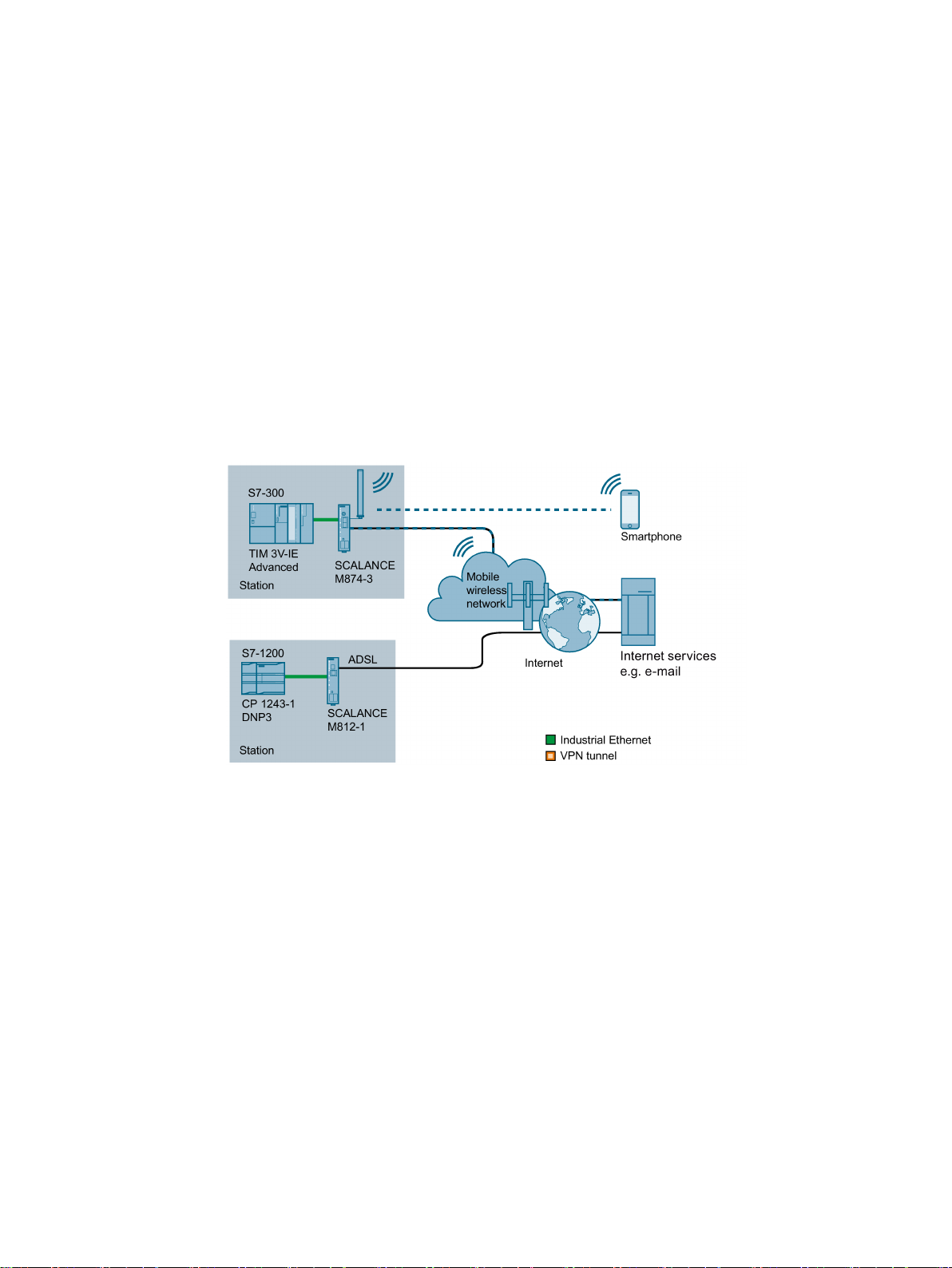
This section provides an overview of how a SCALANCE M-800 with the factory settings can
be integrated in a network and configured. This can be a mobile wireless network
(SCALANCE M87x) or a wired network (SCALANCE M812, SCALANCE M816 or
SCALANCE M826). The device is assigned an IP address. Configuration is performed using
the Web Based Management (WBM).
Figure 1-1 Internet access via a mobile wireless network with the SCALANCE M874-3 via ADSL
with the SCALANCE M812-1
Getting Started, 01/2019, C79000-G8976-C337-07
9

Connecting SCALANCE M-800 to WAN
Required components
Additionally with the SCALANCE M87x
Additionally with the SCALANCE M81x
Steps in configuration
"
1.1 Procedure in principle
● SCALANCE M-800
● Optional if the device is not mounted directly. Standard rail with fittings
● A power supply 24 VDC or 12 VDC with cable connector and terminal block connector
● A network cable complying with the IE FC RJ-45 standard for Industrial Ethernet
● One PC for the configuration
● A suitable antenna
● A SIM card of your mobile wireless provider
The required services, for example the Internet, must be enabled.
● Activation for ADSL
The required steps in configuration depend in part on the device you are using. If the
SCALANCE M826 is used in 2-wire operation, only the configuration step "Setting up
SCALANCE M-800 and the network" is required. After this, the SCALANCE M826 is ready
for operation immediately (out of the box).
1. Setting up SCALANCE M-800 and the network.
For the SCALANCE M826, note the additional information in the section "Connecting
SCALANCE M826 with SHDSL
2. When necessary configure the device with the Primary Setup Tool (PST) or DCP
Discovery
3. If applicable, adapt the IP configuration of the PC.
4. Start Web Based Management.
5. Log in to Web Based Management.
6. Configure the SCALANCE M-800.
– Specify device information
– Set the time of day
– Only with the devices SCALANCE M87x and SCALANCE M81x:
Configure access data
– Only with the devices SCALANCE M87x and SCALANCE M81x:
Set up the host name
– Only with the SCALANCE M826 in 4-wire operation:
Configure SHDSL
– Allow access
10 Getting Started, 01/2019, C79000-G8976-C337-07
Connecting SCALANCE M-800 to WAN
1.2
Setting up the SCALANCE M-800 and the network
Note
Note the security instructions in the operating instructions before you commission the device.
Procedure
WARNING
Use safety extra-low voltage only
SCALANCE M87x
SCALANCE M81x
SCALANCE M826
"
1.2 Setting up the SCALANCE M-800 and the network
1. Unpack the SCALANCE M-800 and check the device for damage.
2. Only with with the SCALANCE M87x: Insert the SIM card.
3. Connect the power supply.
The SCALANCE M874 is designed for operation with safety extra-low voltage. This
means that only safety extra-low voltages (SELV) complying with IEC950/EN60950/
VDE0805 can be connected to the power supply terminals.
The power supply unit for the SCALANCE M power supply must meet NEC Class 2,
according to the National Electrical Code(r) (ANSI / NFPA 70).
4. Connect the device to the network. This step depends on the device and the type of
network:
–
–
–
section "Connecting SCALANCE M826 to SHDSL
5. Connect an Ethernet port (P1, P2, P3, P4) to the PC.
6. Turn the device on. After connecting up, the fault LED (F) is lit red
7. Now, turn on the PC.
(mobile wireless network): Mount the antenna.
(ADSL): Connect the device to the DSL socket on the splitter.
(SHDSL): Wire X1 with X2, for detailed information refer to the
.
Getting Started, 01/2019, C79000-G8976-C337-07
11
Connecting SCALANCE M-800 to WAN
1.3
Connecting M826 to SHDSL
2-wire operation
4-wire operation
2-wire operation with factory settings (out of the box)
1.3 Connecting M826 to SHDSL
The SCALANCE M826 can be operated in two ways:
●
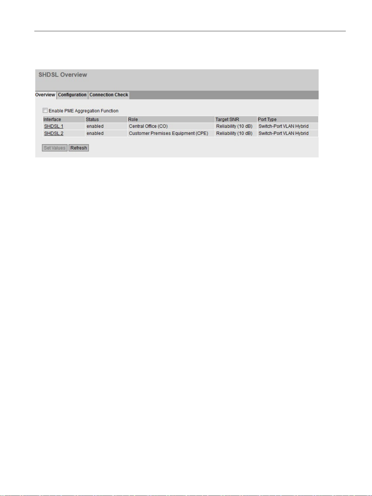
When supplied, the two SHDSL interfaces are set so that two SCALANCE M826 can be
connected via a point-to-point connection. Interface X1 is configured as CO (Central
Office) and interface X2 a CPE (Customer Premises Equipment).
●
Both SHDSL interfaces are put together to form a single connection with a higher
transmission rate. The two interfaces X1 and X2 of one device are configured as CO and
the two interfaces X1 and X2 of the other device as CPE.
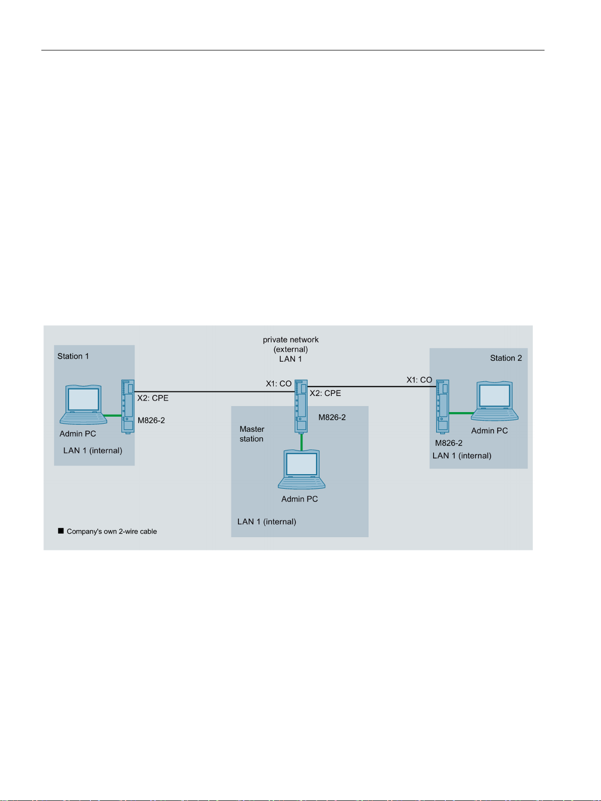
When supplied the SCALANCE M826 is configured so that there is no distinction between
the internal and external network. The SCALANCE M826 is a transparent bridge and
connects network nodes that are in the same IP subnet.
Figure 1-2 The admin PCs represent network nodes that are connected to an Ethernet interface of the relevant
SCALANCE M826. The SCALANCE M826 are connected together via the company's own 2-wire cable.
12 Getting Started, 01/2019, C79000-G8976-C337-07
Connecting SCALANCE M-800 to WAN
Settings used
1.3 Connecting M826 to SHDSL
Figure 1-3 Factory settings for the devices of the configuration example
Getting Started, 01/2019, C79000-G8976-C337-07
13
Connecting SCALANCE M-800 to WAN
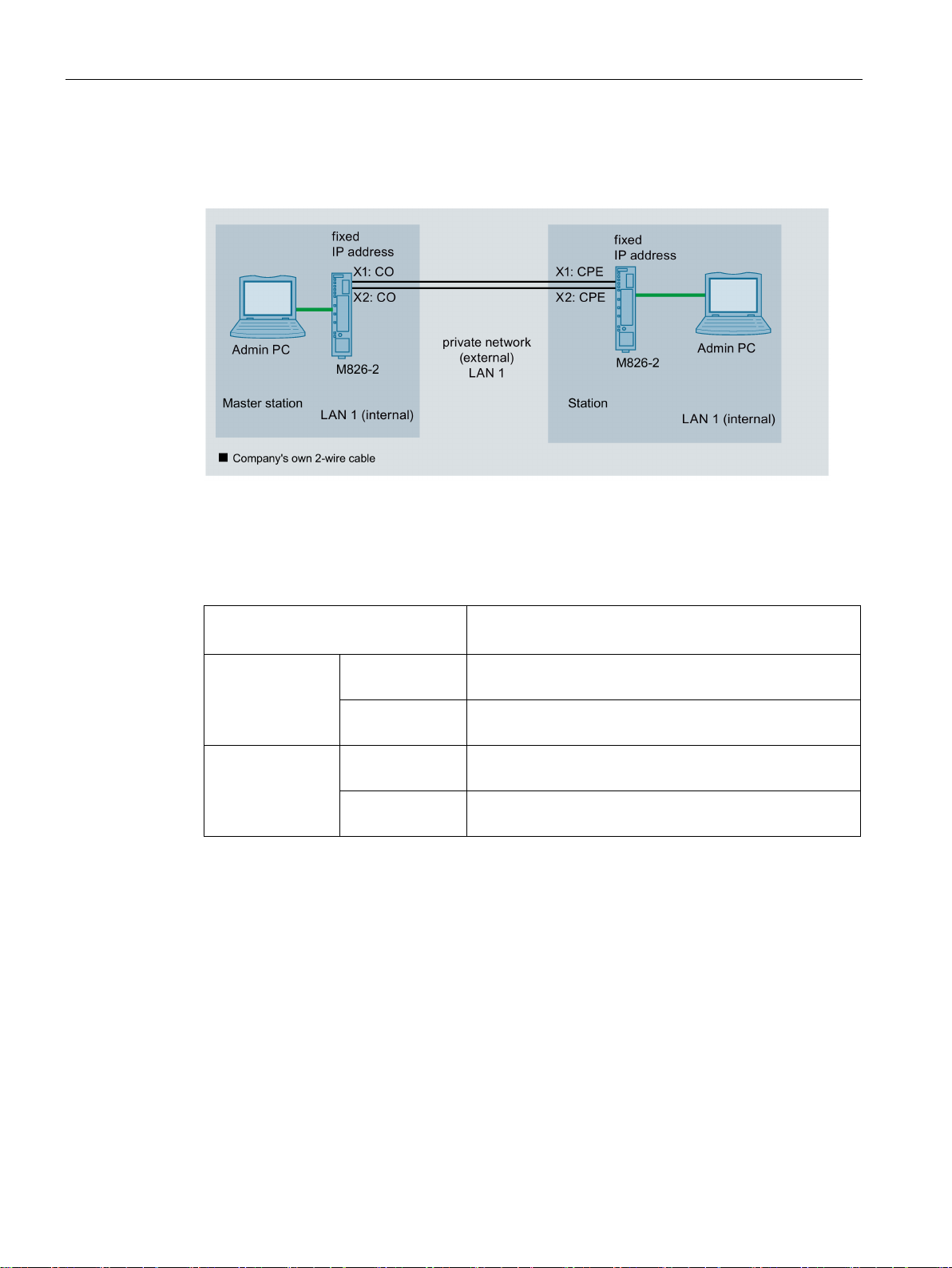
4-wire operation
Settings used
IP address
Subnet mask
255.255.255.0
255.255.255.0
255.255.255.0
255.255.255.0
1.3 Connecting M826 to SHDSL
Figure 1-4 The admin PCs represent network nodes that are connected to an Ethernet interface of
the relevant SCALANCE M826. The two SCALANCE M826 are connected together via
two of the company's own 2-wire cables.
Master station
Station M826 192.168.100.10
M826
Admin PC 192.168.100.20
Admin PC 192.168.100.40
192.168.100.1
14 Getting Started, 01/2019, C79000-G8976-C337-07
Connecting SCALANCE M-800 to WAN
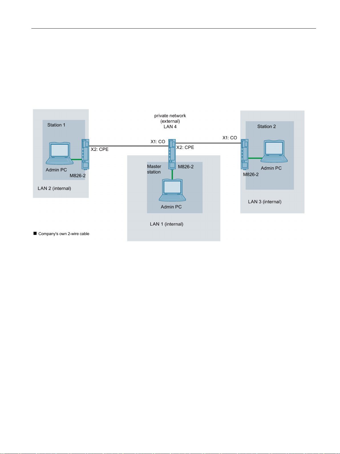
In routing mode
1.3 Connecting M826 to SHDSL
In this example, three different IP subnets will be interconnected via the SCALANCE M826.
For this connection, there must be a one SHDSL interface of a device in the role of CO and
the other in the role of CPE. Since the SCALANCE M826 devices operate in routing mode,
there is a division into external and internal networks. This means that the SHDSL interfaces
and the Ethernet interfaces are located in different IP subnets. In this mode, the security
functions (IPsec VPN, firewall, NAT/NAPT) are available.
Figure 1-5 SCALANCE M826 in routing mode: The network nodes are in different IP subnets. The SHDSL interfaces are
connected together via the company's own 2-wire cables.
Getting Started, 01/2019, C79000-G8976-C337-07
15

Connecting SCALANCE M-800 to WAN
Settings used
Interface
IP address
(external)
255.255.255.0
(internal)
255.255.255.0
(external)
255.255.255.0
(internal)
255.255.255.0
(internal)
255.255.255.0
(external)
255.255.255.0
(internal)
255.255.255.0
(internal)
255.255.255.0
1.3 Connecting M826 to SHDSL
Master
station
Station 1 M826
Station 2 M826 SHDSL
M826
Admin PC Ethernet
Admin PC Ethernet
Admin PC Ethernet
SHDSL
Ethernet
(internal)
SHDSL
Ethernet
Ethernet
Vlan 2 192.168.184.2
Vlan 1 192.168.100.1
255.255.255.0
192.168.100.20
Vlan 2 192.168.184.22
Vlan 1 192.168.11.2
192.168.11.40
Vlan 2 192.168.184.42
Vlan 1 192.168.50.2
192.168.50.40
16 Getting Started, 01/2019, C79000-G8976-C337-07

Connecting SCALANCE M-800 to WAN
1.4
Adapting IP settings
Introduction
SCALANCE M826
SCALANCE M87x and SCALANCE M81x
1.4.1
Configuration with the Primary Setup Tool (PST)
Introduction
Requirement
1.4 Adapting IP settings
To ba able to access a SCALANCE M-800 with the Web Based Management, the device
must have an IP address.
You have the following options for assigning an IP address to devices with factory settings
for the first time:
● Primary Setup Tool (PST)
● DCP Discovery (as of firmware version V4.3)
Access via DCP is write-protected as soon as you enter the password of the factory-set user
"admin". An IP address can be read, but can no longer be changed.
The SCALANCE M826 is supplied without a preset IP address, because for this device there
are applications that require no further configuration (out of the box). In these cases, no
access to the Web Based Management is necessary and therefore no IP address either. The
device will, however, attempt to obtain an IP address from a DHCP server if it is available in
the network. In all other cases, the device must first be assigned an IP address.
The devices SCALANCE M87x and SCALANCE M81x are supplied with the following factory
settings:
● IP address: 192.168.1.1
● Subnet mask: 255.255.255.0
If you enter the IP address "192.168.1.1" in the address box of a Web browser on a
connected PC (in the examples called "admin PC"), you come directly to the WBM of the
device. However, a change to the factory settings may be necessary due to address areas
already configured in the existing network.
The following section describes the procedure when using the PST.
● Device with factory settings
Getting Started, 01/2019, C79000-G8976-C337-07
17
 Loading...