

Siemens SBGA-34 Installation Instructions Manual
INSTALLATION INSTRUCTIONS
JA-BI24 (7 WIRE)
JS-24 (1 WIRE) FROM PIN 3 OF LAST MODULE
-
3
5
7
9
10
7
7
122
Model SBGA-34
Audible Base
INTRODUCTION
The ModelSBGA-34 Audible Base from Siemens Industry, Inc., consists of a standard Series 11 base
combined with an audible device compatible with all H-series, 8700 series, Desigo and Cerberus series
addressable detectors. All field wiring terminates at two four-position terminal blocks located on the back
of the unit. The SBGA-34 is used with the polarity insensitive HFP-11, HFPT-11, HFPO-11, SFP-11*,
SFPT-11* and SFPO-11*,8710, 8712, 8713, FDO421, FDT421, FDOT421, FDOOT441, FDOOTC441,
OP921, OH921, HI921, OOH941, OOHC941 detectors. The SBGA-34 operates as described below
(Refer to Figures 1, 2, 3, 4, 5, 6 and 7 for proper wiring connections).
*SFP-11, SFPT-11 and SFPO-11 detectors are approved for use in CANADA only.
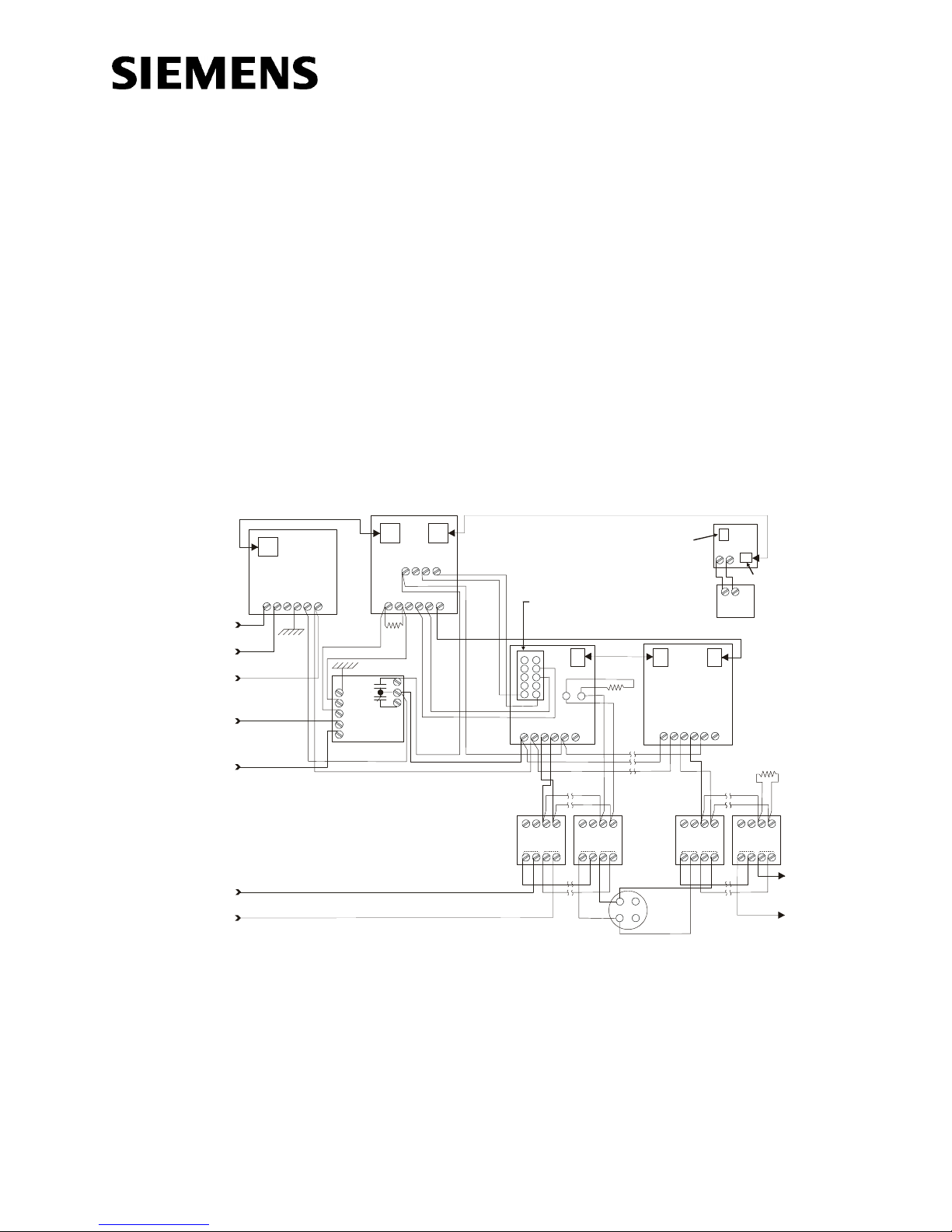
POWER INPUT
120 VAC, 50/60Hz
CONNECTED TO GROUND
REFERENCE OF THE PANELS
IT’S CONNECTED TO (REFER
TO TABLE X FOR GROUND
CONNECTION)
LINE 2
NOTE 4
LINE 1
2. Use a Model MPI-2 mounting plate to mount a HTRI-R in a System 3
3. Tone selection (refer to page 7 for more information).
4. HTRI-R and SBGA-34 are polarity insensitive. Line 1 and Line 2 can
LINE 1
FROM DLC LOOP OF SYSTEM OR FS-DLC LOOP OF FS-250 SYSTEMFIREFINDER-XLS
NOTE 4
LINE 2
JA-BI20 (3 WIRE)
BI-35
5
4
3
2
1
NOTE 2
HTRI-R
MODEL
EL-31
P1 P2
8
9
7
3.6K,
1/4W,
8
7
6
10
PS-35
P1
4 4
5 5
6 6
3 3
2 2
1 1
FOR CONNECTION
TO SLC LOOP
polarity must be maintained or audible base will not operate properly.
Each audible base must be tested to verify operation.
enclosure. HTRI-R relay should be programmed to activate on
appropriate alarm condition. For more detailed wiring information, refer
to the HTRI-R Installation Instructions, P/N 315-033300.
be either line of the loop.
NOTE:
WHEN THE OPTIONAL MM-35 IS NOT USED,
A SUPERVISORY CONNECTION MODEL
JP-BE MUST BE INSTALLED AT P2 IN THE
LAST BC-35 OR BE-35 MODEL.
FOR P1 CONNECTION USE
JA-24 OR EQUIVALENT, AND
REWORKAS NECESSARY
JA-5
(10 WIRE)
1/4W,
AA-30U
5
3
2 2
1
MODEL
EL-31
6
-
-
+
SBGA-34
STYLE Z
+
SBGA-34
5
6
24 VDC
BATTERY
AE-30U
1
- -
DB-11
(CLASS A)
5
3
(CLASS B)
BC-35
7
-
6
+
STYLE Y
12-PIN
PLUG
1/4W,
MODEL
EL-31
+ +
LINE 2
TO NEXT
SBGA-34, DB3S,
LINE 1
Figure 1
Installation/Wiring Diagram for SBGA-34 Powered by AuxiliaryPower Supply with Battery Backup
Siemens Industry, Inc.
Building Technologies Division
Florham Park, NJ
P/N A6V10383428_a_en--
FROM DLC LOOP OF
ZONE 7
-
FIREFINDER-XLS
SYSTEM
LINE 1
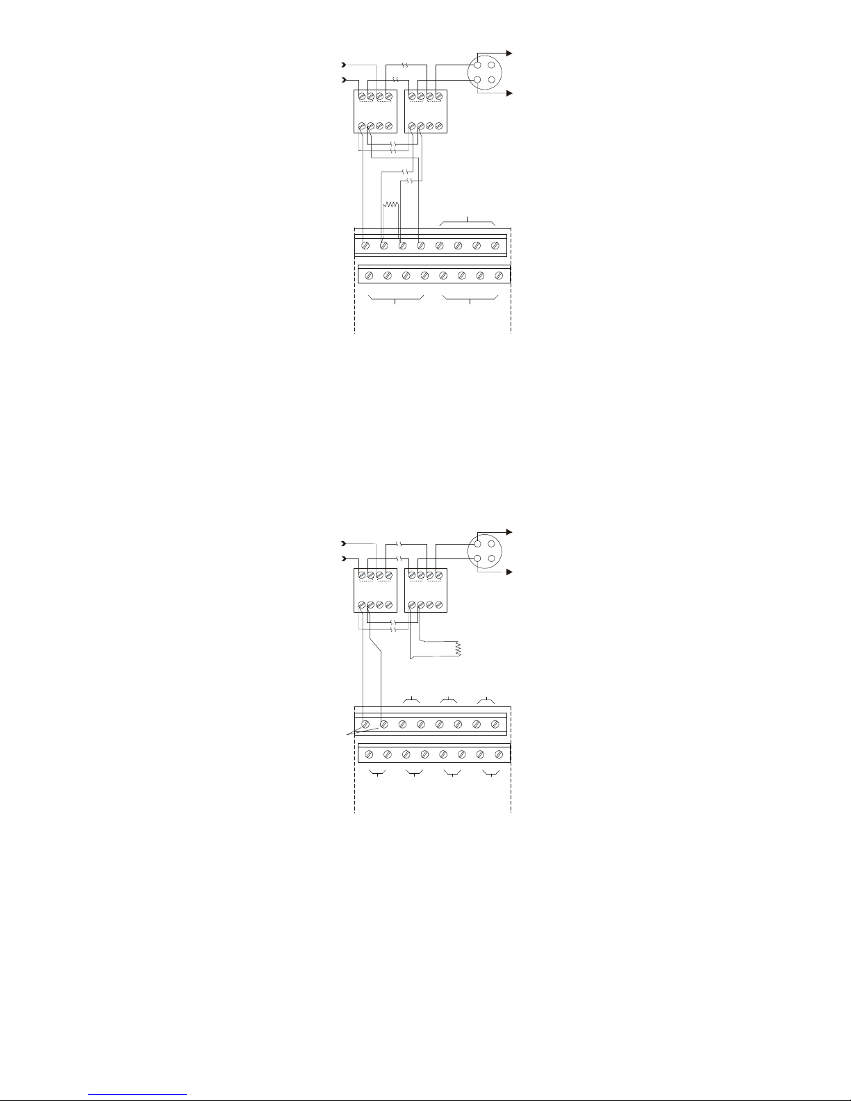
1. Polarity shown in active state at terminals 1 and 2 of SBGA-34 and 1-4 of ZIC-4A.
Proper polarity must be maintained or audible base will not operate properly. Each
audible base must be tested to verify operation.
2. Tone selection (refer to page 7 for more information).
3. SBGA-34 terminals 5-8 are polarity insensitive. Line 1 and Line 2 can be either line
of the loop.
4. SBGA-34 shown Style Z (Class A). It may also be wired as Style Y (Class B).
5. ZIC-4A Notification Applicance Circuits provide 4 outputs that can be configured for
Class A. or Class B. Refer to the ZIC-4A Installation Instructions, P/N 315-033050.
6. EOL resistor, 24k ohms, ½ watt, 5%, P/N 140-820405.
7. For synchronized operation using the ZIC output, tone selection in the SBGA-34
must be set to Steady.
8 87 76 65 5
SBGA-34 SBGA-34
1 12 23 34 4
+
+
NOTE 2
-
+
1/2W
+
24K
5%
--
-
NOTE 2
1b
1a
DEVICE
LINE 1
Figure 2
Installation/Wiring Diagram for SBGA-34 Audible Powered by ZIC-4A (FireFinder-XLS System)
FROM DLC LOOP OF
FIREFINDER-XLS
SYSTEM
LINE 1
8 87 76 65 5
SBGA-34 SBGA-34
1 12 23 34 4
+
+
-
-
NOTE 2NOTE 2
1b
1a
24K
5%
+
ZONE 1
ZONE 5
Proper polarity must be maintained or audible base will not operate properly. Each
audible base must be tested to verify operation.
2. Tone selection (refer to page 7 for more information).
of the loop.
4. SBGA-34 shown as Style Y (Class B).
Class B. Refer to the ZIC-8B Installation Instructions, P/N 315-048670.
6. EOL resistor, 24k ohms, ½ watt, 5%, P/N 140-820405.
7. For synchronized operation using the ZIC output, tone selection in the SBGA-34
must be set to Steady.
DEVICE
LINE 1
Figure 3
Installation/Wiring Diagram for SBGA-34 Audible Powered by ZIC-8B (FireFinder-XLS System)
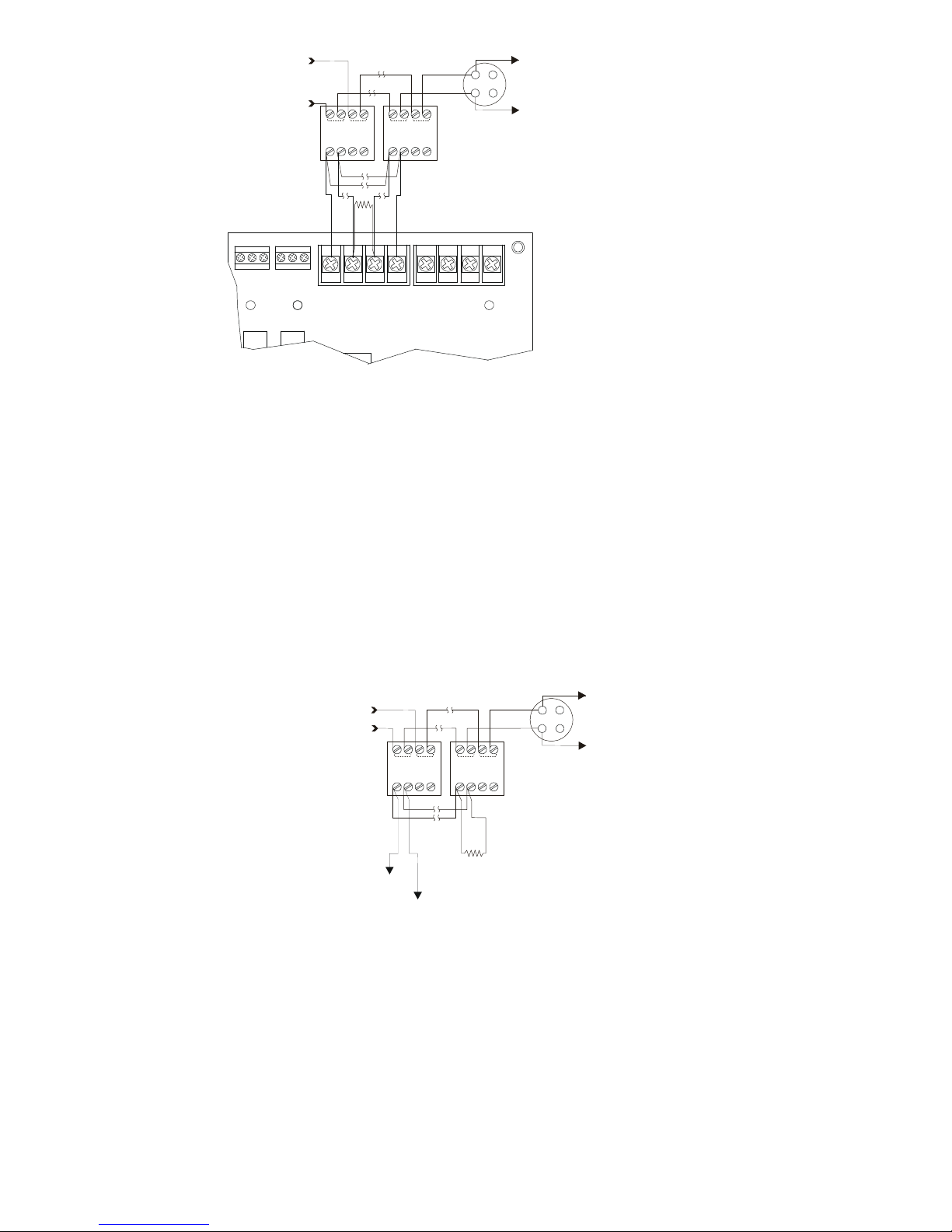
FROM FS-DLC OR FDLC
TO NEXT
LOOP OF FS-250
OR FS-250C SYSTEM
LINE 1
NO NCCNC NO
C
TB7
of FS-250/FS-250C NAC cirucits. Proper polarity must be maintained or audible
base will not operate properly. Each audible base must be tested to verify operation.
2. Tone selection (refer to page 7 for more information).
of the loop.
4. SBGA-34 shown Style Z (Class A). It may also be wired as Style Y (Class B).
5. FS-250/FS-250C NotificationApplicance Circuits (TB12 and TB13) provide 4
outputs that can be configured for Class B or two outputs that can be configured for
Class A. Refer to the FS-250 Operation, Installation and Maintenance Manual, P/N
315-049353, or the FS-250C Operation, Installation and Maintenance Manual, P/N
315-049589C, as applicable, to set jumpers JP1-4 for Class A or Class B operation.
6. EOL resistor, 24k ohms, ½ watt, 5%, P/N 140-820405.
8 87 76 65 5
SBGA-34 SBGA-34
1 12 23 34 4
+
NOTE 2
-
24K
1/2W
5%
1-
1+
TB8
+
-
NOTE 2
TB12
1b
1a
DEVICE
LINE 1
Figure 4
Installation/Wiring Diagram for SBGA-34 Audible Powered by NAC Circuits (FS-250/FS-250C Systems
and MPC6000/MPC7000)
1b
1a
DEVICE
LINE 1
TO PAD-3
NAC CIRCUIT
NOTE 5
be maintained or audible base will not operate properly.Each
audible base must be tested to verify operation.
2. Tone selection (refer to page 7 for more information).
3. SBGA-34 is polarity insensitive. Line 1 and Line 2 can be either
line of the loop.
4. SBGA-34 shown Style Z (Class A). It may also be wired as
Style Y (Class B).
5. Max. Current 3.0 AMPS. Refer to PAD-3 Installation Instructions,
P/N 315-099082.
8 87 76 65 5
SBGA-34 SBGA-34
1 12 23 34 4
+
TO PAD-3
NAC CIRCUIT
-
+
-
NOTE 2NOTE 2
EOL 2.2K, 1/2W
P/N 140-820380
LINE 1
Figure 5
Installation/Wiring Diagram for SBGA-34 Audible Powered by PAD-3
 Loading...