

Siemens SATURN IIE EPABX, SATURN IIE Installation Test Procedures
Siemens Practices
Installation Series
:
A30808-X5130-8120-1-8928
1
Issue 1, May 1986
’
1
!
Issued by Office Systems Group
5500 Broken Sound Boulevard
N.W., Boca Raton,
Florida 33431
--___________-
Siemcns Information Systems, Inc.
(305) 994-8100 l Telex: 515052
----- -
..-
-----
Printed in U.S.A.
SATURN
IIE
EPABX
A30808X5130-8120-1-8328
Installation Test Procedures Issue 1, May
1906
SECTION
PAGE
l.CO INTRDCUCTlON
............;.............
.1-l
Purpose ..................................
l-l
scope ....................................
1-l
Siemens SATURN
IIE
Practices ................. l-l
Siemens Customer Support Services. ...........
l-l
2.00
PREP/%KGXIY
ACTIVITY ...................
2-1
Cener21.
.................................
2-1
Test Equipment Required. ...................
2-l
Handling Precautions for
PC&
with
MOS Integrated
Circuiis.
....................
2-l
PC6
Removal and Replacement Guidelines.......
2-1
Initial Visual Inspection Procedures
..............
2-1
3.CO
GROUND TESTS ..........................
3-l
General.
..................................
3-l
System Ground Test. ........................
3-1
Shelf Ground Continuity Test. .................
3-1
4.00 POWER-UP TESTS ........................
4-l
Genera I..................................
4-1
Power-Up/Output Voltage Tests. ...............
4-l
5.00
OPERATING PROGRAM
LOAD!NG
............
5-1
General.
..................................
5-1
Loading
Operafing Dis!~.
.....................
5-l
Inputting CMU
Data
to
Floppy
Disk. ............
5-l
&CO
ON-FINE
DlAGrGxTlC
TESTS ...............
6-3
General.
..................................
6-l
Connection of Maintenance Phone
and Modem ..............................
6-l
MDF Cross-Connecting
Prccedures.
............
6-1
System Diagnostic Tests; ....................
6-12
7.CO
INSTALLATION TEST
PRCCEDURES CHEC#L!ST
7-l
General
...................................
7-l
l=lGURE
PAGE
2.00 Signal
Cab!e
Distribution for the SATURN
IIE
System (Basic Cabinet). ................
2.01 Signal Cable Distribution for the SATURN
IIE
System (Expansion Cabinet).
............
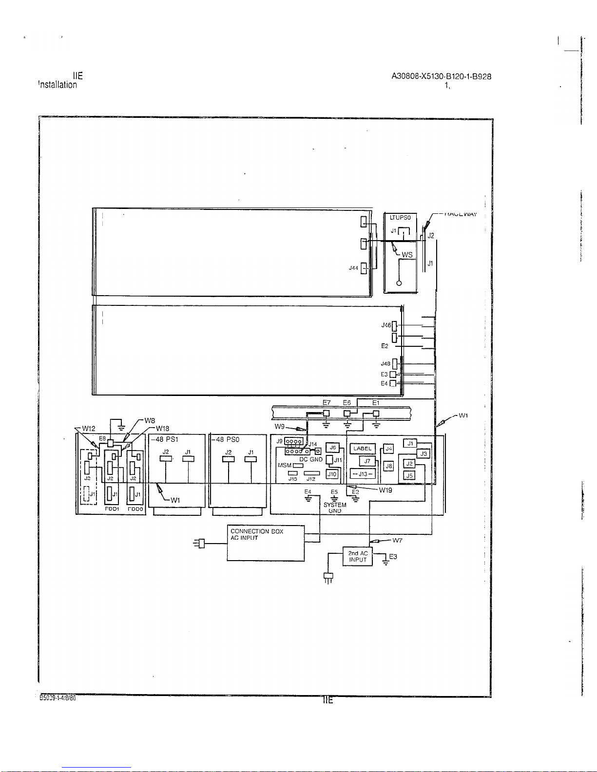
2.02 Power/Ground Distribution for the SATURN
IIE
System (Basic Cabinet). ................
2.03 Power/Ground Distribution for the SATURN
IIE
System (Expansion Cabinet) .............
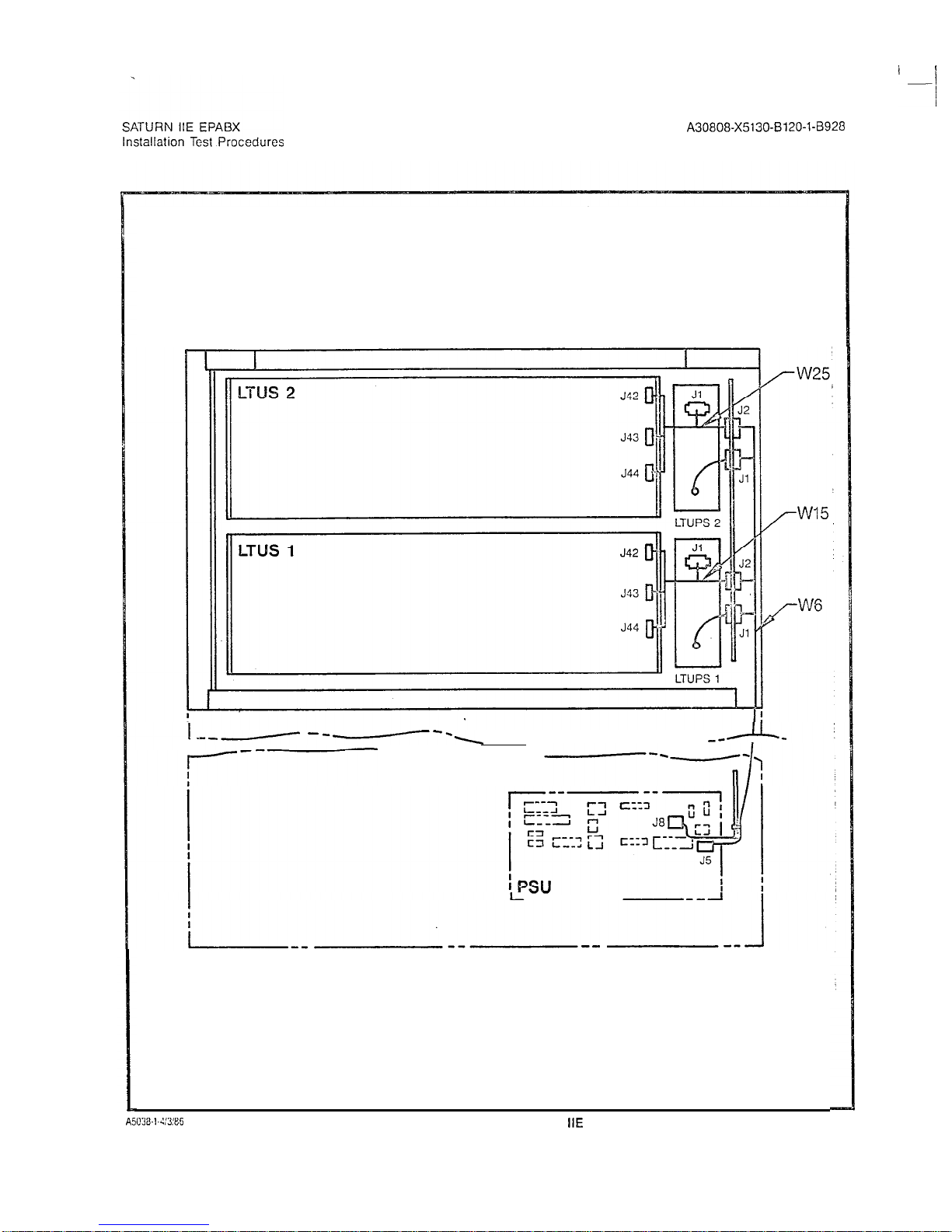
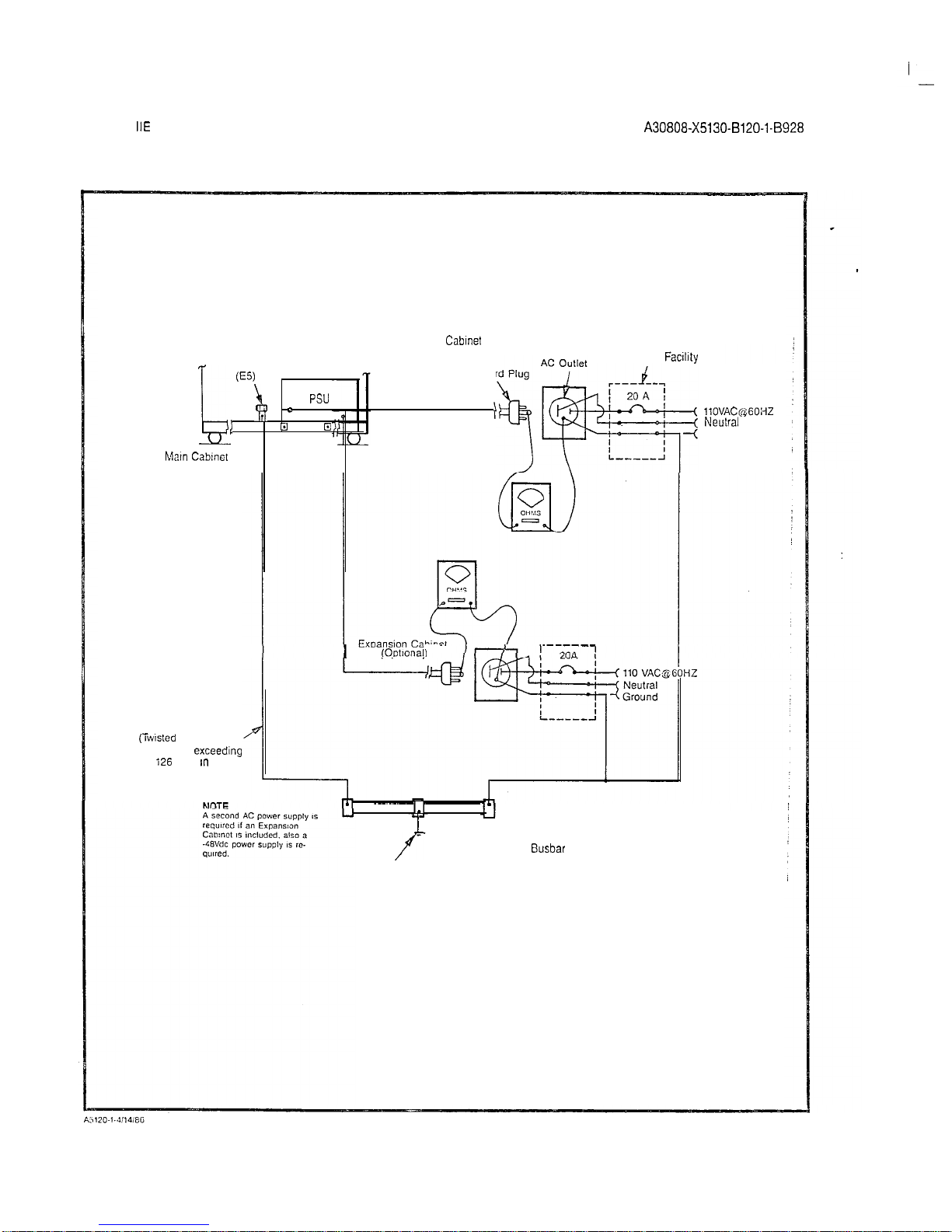
3.00 System Ground Test Connections
..........
3.01 Shelf Ground Continuity Test Connections.
...
4.00 Location of Input Voltage Connectors on
Basic Backplane. .....................
4.01 Location of Input Voltage Connectors on
LTU Backplane .......................
5.00 Floppy Disk and Storage Envelope .........
5.01 Power System Unit (Front View).
...........
5.02 Floppy Disk Loading Procedures.
..........
5.03
CIOP
Printed Circuit Board ...............
6.00 Maintenance Phone and Maintenance-Related
Cress-Connections ....................
6.01
Modem
Cross-Connections ...............
.
2-4
2-5
2-6
2-7
3-2
3-3
. .
4-5
.
4-6
5-l
5-4
5-5
5-6
6-2
6-z
6.02 Single -Line Telephone Cross-Connections
Using SLMA
PCB
. . . 6-3
6.03 Single
-Line
Telephone Cross-Connections
Using
SLAi6
PCB
6.04 Siemens Digital
Teiephone
Cross-Connections
Using SLMD PCB. .
6.05 SATURN Attendant Console Cross-Connections
6.06 CO and
CID
Trunk Cross-Conneciions .
6.07 Two-Wire (Type I) E&M Trunk
Cross-Connec?ions
6.08 Four-Wire
(T;lce
I)
E&M
Trunk Cross-Connections
6-3
63
G-4
E-5
G-5
G-S
_.
6.09 Two-Wire
(Type II)
E&M Trunk Cross-Connections . 6-6
6.10 Four-Wire
(?ype
II)
E&M
Trunk Cross-Connections . 6-7
6.il
Recorded
Anncuncement
(DID and Tie Trunk
Vacant Number Intercept, and ACD
Announcement
Service)
Cross-Connections 6-7
6.12 Code
Ca!ling
(With or Without Answerback)
Cross-Connections . . 6-8
6.13 Dial Ciciation
(DTMF)
Cross-Conneciions. 6-8
6.14 Music-en-Hold Cross-Connections Using
TMBA4
PCB . . . . 6-9
6.15 Music-on-Ho!d Cross-Connecticns Using
SLMAISLA16
PCB . . . . . . 6-9
6.16 Paging With Answerback Cross-Connections 6-10
6.17 Paging Without Answerback Cross-Connections. . 6-10
6.18 Universal Night Answer (UNA) Cross-Connections
E-11
6.49 Attendant
Conscie
Keypad and
Fcaturo
Button
Depiassion
Ssquonce
G-:3
620
Siemens
DYIiD Te!ephono Buttcn Ccpressicn
Sequence . . . . . . . . . . . . . .
6-21
6.21 Siemens JR-DYAD
Te!ephone
Euitcn
Depression
Sequence
. . 6-23
1.00 Mnemonics Used in This Practice .............. l-l
2.CO
PCB and
Powar
Supply Removal
Guidelines
.....
2-2
2.01 Visual
Inspeciion
...........................
2-3
3.00 System Ground Test. ........................
3-l
3.01 Shelf Ground Continuity
Test
..................
3-1
4.00 Power-Up/Output
Voitnge
Test .................
4-l
5.00 Loading Procedures fcr Operating Disk. .........
5-2
5.01
CIOP
DIP
Swiich
Settings ....................
5-3
5.02 LED Display Values for Leading Errors
..........
5-4
6.00 Tone Generator Test
........................
6-13
6.01 Tone
Genera:or
Test
I\!umbers
................
G-i3
6.02 DTMF
Receiver
Test ........................
G-14
6.03 Station Line Test. ..........................
6-14
6.04 DTMF Pad Test
............................
6-15
6.05 Console Test
...............................
6-16
6.06 Attendant Console Displayable Characters. ......
6-19
6.07 Siemens Digital Telephone - DYAD Button Test 6-20
6.08 Siemens Digital Telephone - JR-DYAD
Button Test . . . . .
6.09 Siemens
Digiial
Telephone
-DYAD
Display Test
6.10 Siemens Digital Telephone Displayable
Characters . .
6.11 Outgoing Trunk Test .
6.12 Placing Circuit(s) In-Service
6.13 Taking Circuit(s) Out-of-Service
7.CO Insta!lation
Test Procedures Checklist
G-22
6-24
6-25
6-26
6-27
6-27
7-l
SATURN
IIE
EPABX
installation Test Procedures
A30808-X5130-0120-l-0928
Issue 1, May
1986
.
1.01
Purpose. The equipment comprising the SATURN
IiE
(SATURN Ii-Expanded) System is
compleYely
tested at the factory prior to shipment. The inspections and tests covered in
this practice verify that the EPABX equipment has been
properly installed; ensure that no damage
wasIncurred
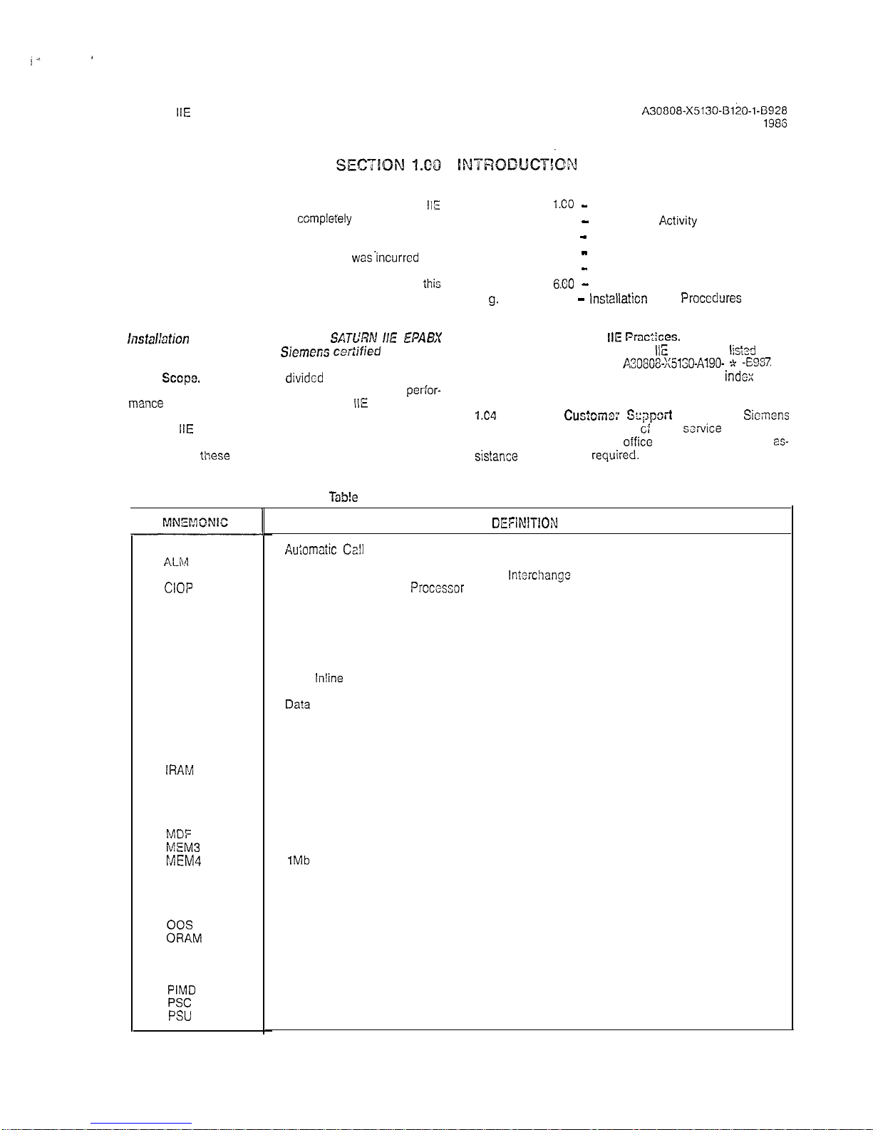
during transit; and confirm that the sysiem is completely operational. Table 1.00 defines the mnemonics usedthroughout
ihis
practice.
CAUTION
lnstalbtion
test procedures on the
SATL’RN I/E EPABX
must be performed only by
Siemer;s cetiified
personnel.
1.02
Sccpe.
This practice is
divided
into the following sec-
tions which are presented in the sequential order of
per-for-
mance
after initial installation of a SATURN
IIE
System. When
additional equipment is installed to an existing and active
SATURN
IIE
System, it is the responsibility of craft person-
nel to determine the sequential order of the test procedures
contained in
tihese
sections.
ACD
Au;omaiic Cafl
Disiribution
ALiVl
Alarm
ASCII American Standard Code for Information
lntarchange
CIOP
Controller/Input-Ouiput
Prccessor
CMU Customer Memory Update
co Central Office
CONF Conference Module
COT
Central Office Trunk
DCI Data Communication Interface
DID Direct Inward Dialing
DIP
Dual
lnline
Package
DP
Dial Pulse
DTE Da?a
Terminal Equipment
DTMF
Dual Tone Multifrequency
EIA
Electronics Industries Association
EPABX
Electronic Private Automatic Branch Exchange
FDD Floppy Disk Drive
IRAM
Input Random Access Memory
LTU
Line/Trunk Unit
LTUPS
Line/Trunk Unit Power Supply
LED Light-Emitting Diode
MCA Memory Control and Attenuation
MDF
Main Distribution Frame
MEM3
25Gkb Memory
MEM4
1Mb
Memory
MOS
Metal Oxide Semiconductor
MRA Material Return Authorization.
MSM
Memory Support Module
MTCE
Maintenance
00s
Out-of-Service
ORAM
Output Random Access Memory
PABX
Private Automatic Branch Exchange
PCB Printed Circuit Board
PEN
Port Equipment Number
PIMD
Premium Instrument Module Digital
PSC
Parallel/Serial Converter
PSU
Power Supply Unit
a. Section
l.CO -
Introduction
b. Section 2.00 - Preparatory
Activiiy
c. Section 3.00 - Ground Tests
d. Section 4.00 - Power-Up Tests
e. Section 5.00 - Operating Program Loading
f. Section
6.80
-
On-Lina Diagnostic Tesis
g.
Section 7.00 -
lnstallaticn
Test
Procedures
Checklist
7.03
Siemens SATURN
IIE Prac:iccs.
The practices, issue
numbers and dates for the SATURN
IIE
EPABX are
lists3
in the
Practices Documentation Index A.30808~X5130-AlgO- * -E987 Al-
ways refer to the !aiest issue of the application
indcx
to ob-
tain the latest issue number of a practice.
724
Siemens
Cus;oma: Sqpsrt
Services.
Sicrnons
maintains a nationwide network
cf
field
service
offices. Con-
tact the Siemens regional
oifice
for any engineering
es-
sistance
that may be
requked.
TaS!e
1.00 Mnemonics Used in This Practice
DEFiN1TfON
i-i
SATURN
IIE
EPABX
Installation Test Procedures
.
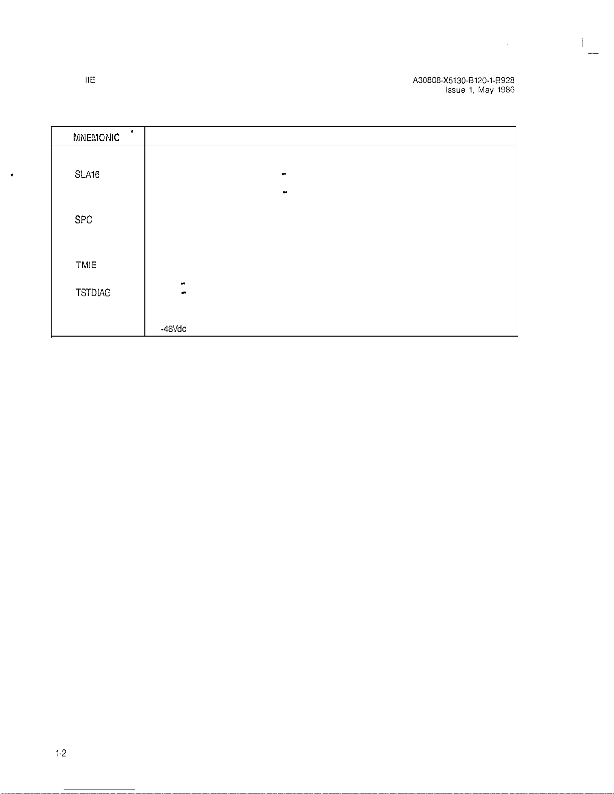
Table 1.00 Mnemonics Used in This Practice (Continued)
[\fiNEMDNIC *
DEFINITION
RAUP Remote Access Unit/Ports
RGEN Ring Generator
S-416
Subscriber Line Module Analog - 16 lines
SLMA
Subscriber Line Module Analog
SLMA-S
Subscriber Line Module Analog - Station
SLMD
Subscriber Line Module Digital
SMXTG
Signal Multiplexer/Tone Generator
SPC
Stored-Program-Controlled
SPG
Single Point Ground
TMBA-2
Two-Wire E&M Trunk
TMBA-4 Four-Wire E&M Trunk
TMBM
Central Office Trunk
TMIE
Direct Inward Dialing Trunk
TMS
Transmission Measuring Set
TSTAPP
Test - Apparatus
TSTDIAG
Test - Maintenance Diagnostic
TTY
Teletypewriter
UNA
Universal Night Answer
ZUNA Zoned Universal Night Answer
-48PS
-48Vdc
Power Supply
l-2
(2 pages)

SATURN
IIE
EPABX
A30808-X5130-B120-l-8928
Installation Test Procedures Issue 1, May 1986
2.01
General. This section describes the test equipment required to perform the installation test procedures, handling
precautions for Printed Circuit Boards
(PCBs)
with Metal Oxide Semiconductor (MOS) integrated circuits, guidelines for
removal and replacement of
PCBs
and powei supplies, and
initial visual inspection procedures.
2.02 Test Equipment Required. The following test equipment is required to perform the procedures contained in this
practice:
a. Digital Multimeter. A digital multimeter of
gocd
com-
mercial quality with an accuracy of + 1.0% or better.
The digital multimeter is used to perform the ground
tests and output voltage tests.
b.
Maintenance Test Phone. For both Dial Pulse (DP) and
Dual Tone Multifrequency
(DTMF)
systems, a lineman’s
test set or a single line
te!ephone.
A modular jack
(MTCE PHONE) is provided on the front
panal
of the
PSU for
conneciing
the maintenance test phone when
equipped with a modular plug. When the maintenance
test phone is not equipped with a modular plug, a station appearance can be used via the Main Distribution Frame
(MDF).
The
mainienance
test phone is used
to perform the on-line diagnostic tests.
c. Data Service Terminal. A Keyboard-Send-Receive
(KSR) daia terminal equipped with a standard ASCII
keyboard and an EIA RS-232C interface (Silent 700
Series - Model 743 KSR - Texas Instruments, or
equivalent). The data service terminal is used to input
installation dependent data (i.e., system data base) into
system memory when the standard data base format
is supplied with the SATURN
IIE
System.
d. -Transmission Measuring Set. A transmission measur-
ing set (TMS) used to measure the transmission quality of a trunk or station (Hewlett Packard HP-355iA or
equivalent). Refer to the manual On-Line
DiagnostiC
Tests, Outgoing Trunk Test and Station Line
Tosl.
2.03 handling Precautions for
PCBs wifh MCS Integmt-
ed
Circuiklt
is important that craft personnel handling
FCBs
with MOS integrated circuits free themselves from electrostatic
charge by touching a grounded cabinet frame before handling
such
PCEs,
or by wearing grounded wrist straps.
Failur:,
to
observe this practice may result in damage to
MO3 PCBs
due to electrostatic discharge.
WARNING
lirazardous
voltages
exist r&h.%
the
eqo&ment
cabins?.
Be extremely careful when
perr”orming fcsa-
incjtroubleshooting
procedures
with
the
oquipmcr;t
panel(s) removed.
2.04
PCB Removal and
P,ep!acemenZ Guide%%
In many
instances during testing, the corrective action for a procedure
in which the proper verification was not obtained requires that
a PCB or a power supply be removed and replaced with a
spare.
Tablo
2.00 provides the guidelines that
shou!d
be
o!)-
served when removing and
rep!acing PCBs
and
powor SI:;X-
plies in an active
sysicm.
2.05
lnifial Visual kspactizn Procedurx.
The
visu’al
in-
spection procedures contained in
Tab!e
2.01 must be
psrfcrmcd
to ensure that the equipment comprising the SATURN
ItE
Sys-
tem has been properly installed and configured to meet the
installation requirements. Before proceeding
wiih
the visual in-
spections, the front, rear and side panels of the
cabinei should
be removed to
allcw
thorough inspection of the equipment.
2-1
-
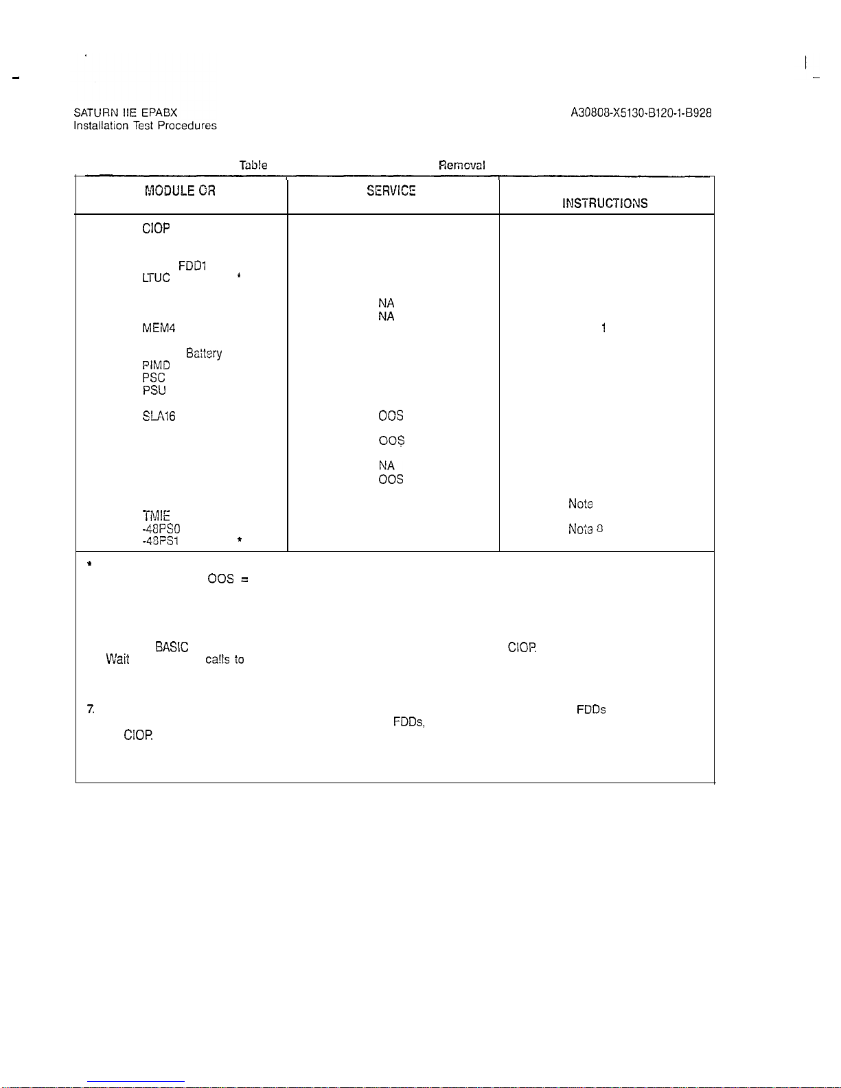
Table
2.00 PC3 and Power Supply
Remcval
Guidelines
I’AODIJLE OR SERVEC”
SPECIAL
UNIT
STATE
INSTRUCTKWIS
CIOP
NA
CONF . NA
DTMF 00s
FDDO,
FDDl
NA
LTUC
f
NA
LTUPS
l
NA
MCA
MEM3
kz
MEM4
NA
MSM
l
NA
MSM
Baitery
l NA
PIMD
00s
PSC
NA
PSU
NA
RAUP
NA
SLAl6
00s
SLMA-0 00s
SLMA-S
003
SLMD 00s
SMXTG
ES
TMBA-2
TMBA-4
00s
TMBM
00s
TMIE
00s
-48PS.l
NA
-48PSt
f
NA
*
Optional depending upon customer/system requirements.
NA = Not Applicable;
00s =
Out-of-Service
Notes 1 and 2
Notes 1 and 2
Note 3
None
Note 4
Note 5
Notes 1 and 2
Notes 1 and 2
Notes 1 and 2
Note 1
Note 6
Note 3
Notes 1 and 2
Note 7
Notes 1 and 2
Note 3
Note 3
Note 3
Note 3
Notes 1 and 2
Note 3
Note 3
No?e
3
Note 3
Note 8
Noie 3
Notes:
1.
System outage (halts call processing). Set BASIC PS circuit breaker on PSU to off.
2.
Open FDD and remove floppy disk before removing PCB. After new PCB is inserted, reinsert floppy disk, close
FDD, set
BASK
PS circuit breaker on PSU to on, and press reset switch on
CIOP
3. VVait
for in-process
ca!ls
i0
complete.
4.
Removal places one-half of ports in shelf out-of-service.
5.
Before removal, set related LTUPS circuit breaker on PSU to off. Removal places all ports in shelf out-of-service.
6.
Battery may be replaced with power applied to system.
7.
System outage (halts call processing). Before removal, set all circuit breakers to off, open
FDDs
and remove flop-
py disks. After replacement, reinsert floppy disks, close
FDDs,
set circuit breakers to on, and press reset switch
on
CIOR
8.
Set related circuit breaker on PSU to off. May halt call processing depending upon system configuration and
traffic. If there are two -48Vdc power supplies (where system includes an Expansion Cabinei), the remaining supply may have sufficient capacity to support system operation.
A30808-X5130-8120-l-8928
Issue 1, May 1986
2-2
I
.-
A30808-X5130-B120-l-8928
Issue 1, May 1986
SATURN
IIE
EPABX
Installation Test Procedures
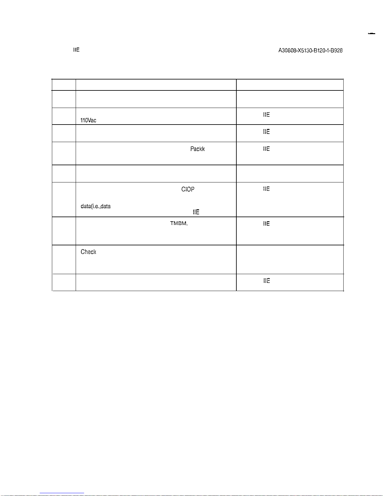
Table 2.01 Visual Inspection
STEP
VISUAL INSPECTION REFERENCE
1
Check that the cabinet ac power cord is not connected to an
electrical outlet.
2
Check that the -48Vdc power supply is strapped for SATURN
IIE
EPABX Installation
11OVac
or 22OVac. Procedures Practice (Section 4.00)
3
Check that all circuit breakers on the Power System Unit SATURN
IIE
EPABX Installation
(PSU) are in the OFF position and fuses inserted. Procedures Practice (Section 4.00)
4
If the MSM is installed, check that the Battery
Packk
is not SATURN
IIE
EPABX Installation
connected but inserted into corresponding position. Also Procedures Practice (Section 4.00)
check that the PSU is strapped for MSM operation.
5
Check that each PCB in the system is withdrawn from its
backplane connector.
6
Check that the DIP switch settings for the
CIOP
board are set SATURN
IIE
EPABX Installation
to meet the operating characteristics of the particular data Procedures Practice (Section 4.00)
service terminal to be used to input the installation-dependent
data(i.e.,data
base) into system memory when the standard
data base format is supplied with the SATURN
IIE
System.
7
Check that each trunk-type PCB (i.e.,
TMEM,
TMIE, TMBA-2 SATURN
IIE
EPABX Installation
and/or TMBA-4) is properly strapped according to the Procedures Practice (Section 4.00)
operating characteristics of the trunk facility of the Central
Office (CO) or distant PABX.
8
Chec!c
that the intercabinet signal and power/ground cabling Figures 2.00 through 2.03
arrangements are complete and all connectors are firmly seated according to the referenced illustrations (Figures 2.00
through 2.03).
9
Check that Berg Clips are on pins 27 and 28 of unused SATURN
IIE
EPABX Installation
signal cable connectors on basic shelf. Procedures Practice (Section 4.00)
2-3
w3 w13
-
I
I
SATURN
IIE
EPABX
,xtallation
Test Procedures
A30808-X5130-B120-l-5928
Issue 1, May 1986
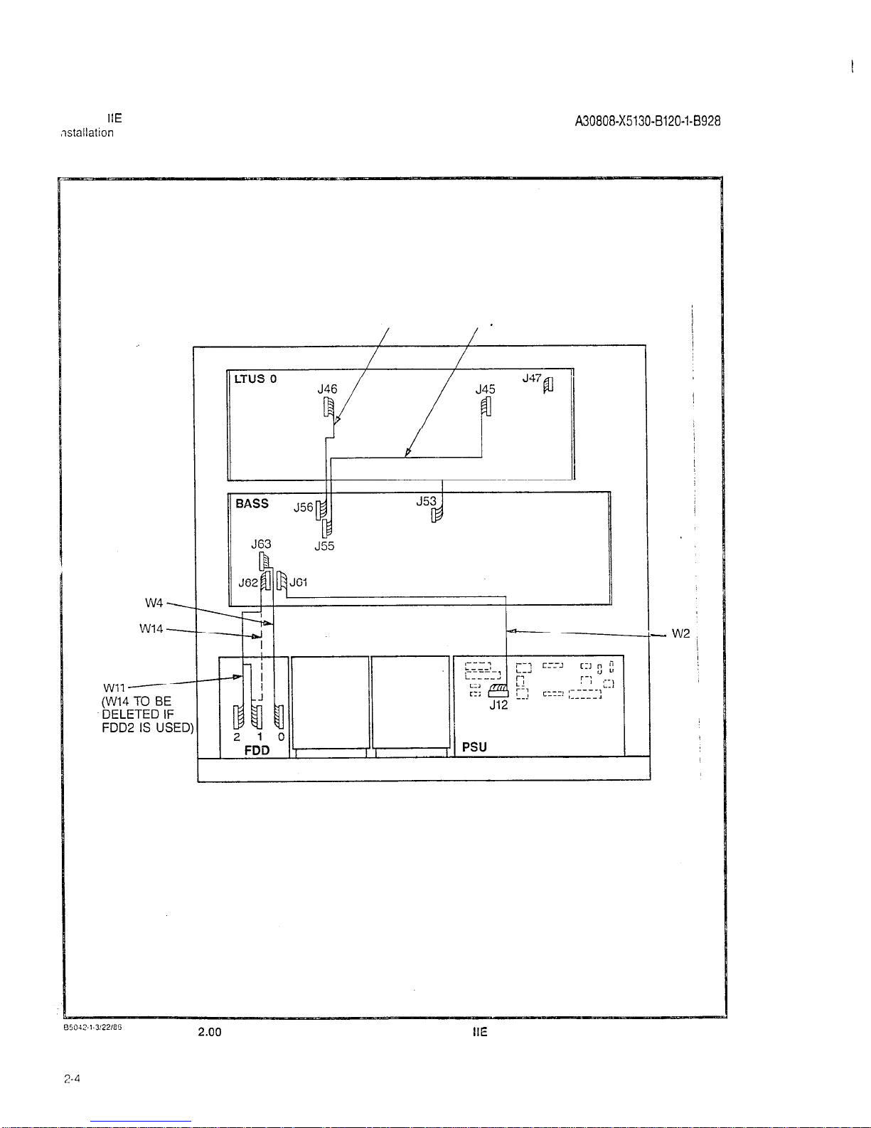
Figure
2.00
Signal Cable Distribution for the SATURN
IIE
System (Basic Cabinet)
SATURN
IIE
EPABX
Installation Test Procedures
A30808-X5130-B120-l-8928
issue 1, May 1986
W23
EXPANSION CABINET
\
I
--- ---
: ]
1
FDD
:
,
i;wi!
i-L--i--
-
_-__
--
LiTJ-. - -
-r-----
*
W22
BASIC CA&NET
A5040-2.313186
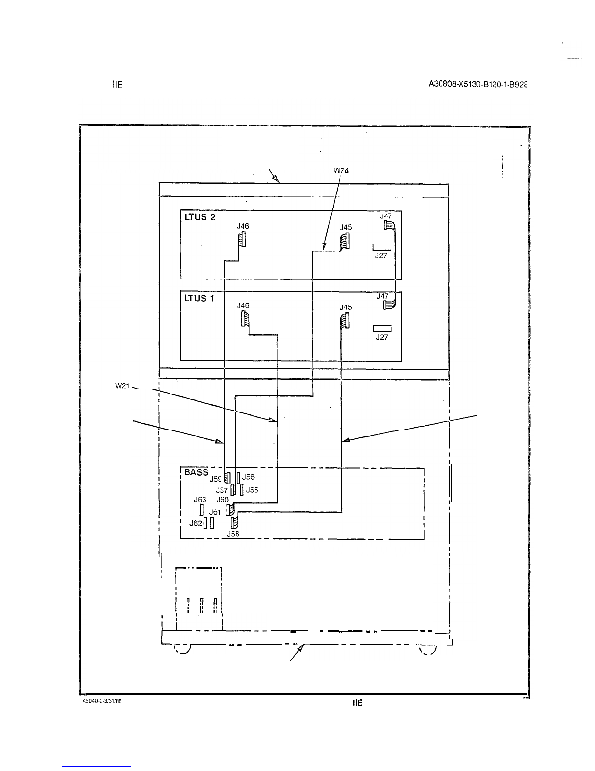
Figure 2.01 Signal Cable Distribution for the SATURN
IIE
System (Expansion Cabinet)
2-5
SATURN
IIE
EPABX
tnstallation
Test Procedures
A30808-X5130-8120-1-8928
Issue 1, May 1986
LTUSO
LINE TRUNK UNIT SHELF
J42
J43
r JP
L
Jl
BASS
BASIC SHELF
El a----
J46
J47
E2
05039.1..wmG
Figure 2.02 Power/Ground Distribution for the SATURN
IIE
System (Basic Cabinet)
2-6
A30808-X5130-B120-l-8920
Issue 1, May 1986
EXPANSION CABINET REF.
L
--M--e--\
----
-,-,
------
-----
BASIC‘CABINET REF.
A5U38-1-4:3:86
Figure 2.03 Power/Ground Distribution for the SATURN
IIE
System (Expansion Cabinet)
2-7 (2-8 blank)
SATURN
IIE
EPABX
A30808-X5130-B120-l-8928
Installation Test Procedures
issue 1. May 1986
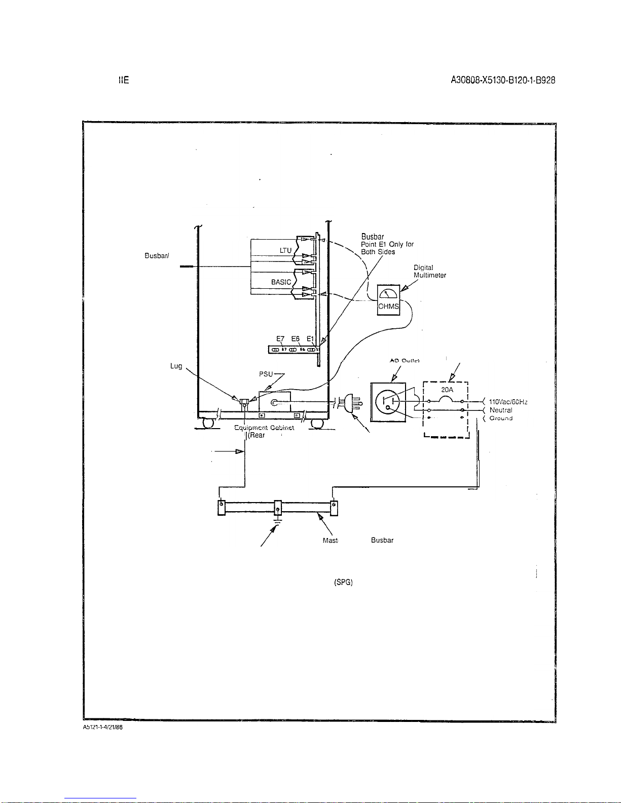
3.01
General. The SATURN HE System must be connected
to an earth ground (i.e., metallic cold water pipe or master ground
busbar)
in addition to the safety ground in the ac power cord.
A
G-gauge
(twisted copper wire) conductor should be connected between the grounding lug E5 located on the bottom of the
cabinet frame and the
snlccted
earth ground (refer to Section
3.00 in the SATURN HE EPABX Installation Procedures practice for details). The following tests must be performed to en-
sure that proper earth ground connections have been
accomplished, and that ground connections within the cabinet
assembly have not been damaged or loosened during shipment.
WARNiNG
Hazardous
voltsgos txkt
within the equipment
csbinef. Ee
extremely ca-ej’Ll
when performing
t~s%i~g/l’roubiesh~oting
procedures with the equipment panel(s) removed.
3.02
System
Grcund
Test. Before proceeding with the test’
procedures indicated in Table 3.00, check that the earth
ground connections are secure and ground conductors are
firmly positioned on grounding lug E5 at
ihe
bottom of the
cabinet frame.
3.03
Shelf Ground Continuity Test. Each LTU shelf assem-
bly within the cabinet assembly is grounded via two vertical
busbars.
Beiore proceeding with the test procedures indicat-
ed in Table 3.01, check that each shelf backplane is
iniercon-
netted
with the
busbar
flanges and adequately secured into
position.
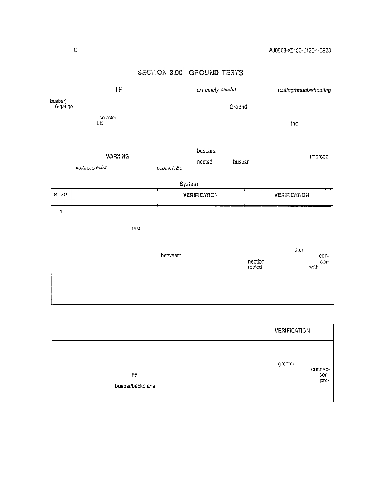
Table 3.00
System
Ground Test
PROCEDURE
VERlFlCATlON
IF
VERlFlCATION
IS NOT OBTAINED
.l
If connected, remove ac power cord
from commercial power outlet.
2
Short digital multimeter
tesi
leads
together and noie resistance of test
leads.
3
Set digital multimeter to lowest
Resistance measured should be If a reading greater
ihan
2 ohms is
resistance range and connect its
betweem
0 and 2 ohms greater than obtained, the faulty ground
con-
leads between the U-ground pin of the measured test lead resistance.
nection
must be isolated and
cor-
the ac power cord and the U-ground
rected
befora continuing
wi?h
the
socket in the commercial power
installation test procedures
outlet (refer to Figure 3.00 for details).
4
Repeat procedure with second ac Same as step 3 above. Same as step 3 above.
power cord if optional expansion
cabinet is incorporated into system.
Table 3.01 Shelf Ground Continuity Test
STEP
PROCEDURE
VERIFICATION IF
VERIFICATiON
IS NOT OBTAINED
1
If connected, remove ac power cord
from commercial power outlet.
2
Set digital multimeter to lowest Resistance measured should be If a reading
greator
than 1 ohm is
resistance range and connect its between 0 and 1 ohm greater than obtained, the faulty ground
connec-
leads between ground lug E5 located the measured multimeter test lead
tion must be corrected before
con-
at the bottom of the cabinet frame,
resistance. tinuing the installation test
pro-
and one of the
busbar/backplane
cedures.
attaching screws for each existing
LTU shelf (refer to Figure 3.01)
3-l
SATURN
IIE
EPABX
A30808-X5130-B120-l-8928
Installation Test Procedures Issue 1, May 1986
BASIC Cabinet
GND
LUG
Fuse Box Facility
(ES)
,
5,
B D
Power co
PSU
f
llOVAC~$GOi-fZ
El
El
Neulral
Ground
hlatn Cabmel
(Rear View)
Recommended: B-gauge
(iwtsted
Copper Wire)
conductor not
exceedmg
i26
feet m length.
I
(Ootlonall
I.1
f
Master Ground
Busbar
Earth Ground Note: Single Point Ground (SPG) configuration IS shown
Figure 3.00 System Ground Test Connections
3-2
SATURN
IIE
EPABX
Installation Test Procedures
A30808-X5130-8120-1-8928
Issue 1, May 1986
Busbar/
Backplane
-
Attaching
Screws
GND
Lug
No. E5
’
7
-
Recommended: 6 Guage
(twisted copper wire) conductor
not exceeding 126 feet in length.
I(Rear
View)
Busbar
Grounded at
Fuse Box Facility
\
I
L
---_
-I
Power
Cord Plug
7
Master Ground
Busbar
Earth Ground
Note: Single Point Ground (SPG) configuration is shown
Figure 3.01 Shelf Ground Continuity Test Connections
3-3 (3-4 blank)
I
-_
SATURN
IIE
EPABX
installation Test Procedures
A30808-X5130-BlZO-l-8928
Issue 1, May 1986
SECTION 4.00 POWER-UP TESTS
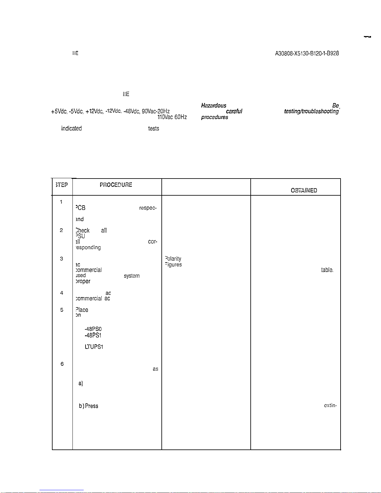
4.01
General. The SATURN
IIE
System makes use of distributed power in the equipment cabinet. Several power supplies are used in the system. These power supplies provide
+5Vdc, -SVdc, +12Vdc, -12Vdc, -48Vdc, 90Vac-20Hz
ringing
voltage and message waiting voltage, from a
11OVac 60Hz
input power source. After satisfactorily performing the ground
tests
indicaied
in Section 3.00, the following
tests
must be per-
formed to ensure that proper power cable connections have
been accomplished and that the power supplies inside the
cabinet assembly have not been damaged during shipment.
WARNING
Hazardous
voltages exist within the equipment cabinet.
Be
extremely
careful
when performing
testin@roubkshootjng’
pmcedures
with the equipment panel(s) removed.
4.02
Power-Up/Output Voltage Tests. Before proceeding with
the test procedures indicated in Table 4.00, check that all power cable assemblies are properly secured into their corresponding locations. Note that the test procedures in Table 4.00 include
procedures for testing the optional MSM, when equipped in the
system.
Table 4.60 Power-Up/Output Voltage Test
YiEP
PROCEDtJRE
f not previously done, extract each
‘CB
in the system from its
respec-
ive backplane connector in basic
md
LTU shelves.
Check
that
all
circuit breakers on the
‘SU
are in the off positions and that
311
fuses are inserted in their
cor-
,esponding
locations.
Jsing the digital multimeter (or an
3c
polarity indicator), verify that the
:ommercial
ac power receptacle
Jsed
for powering the
systsm
has the
Iroper
polarity.
Connect the
ac
power cord(s) to the
zommercial
ac
power receptacle(s).
?lace
the following circuit breakers
on
the PSU to the on (up) position:
a) Basic PS
b)
-48PSO
c)
-48PSl
(if equipped)
d) LTUPSO (if equipped)
e)
LTUPSl
(if equipped)
9 LTUPS2 (if equipped)
If the optional MSM module is
equipped in the system, proceed
2s
follows:
2)
If not previously done, connect
and insert battery pack into
the MSM assembly.
b)Press
the BATTERY TEST
switch on the PSU and
release after verification has
been obtained.
VERIFICATION
‘olarity
indication must coincide with
=igures
3.00 and 3.01.
The associated green LED should
light steadily.
IF VERIFICATION
IS NOT
08TAlNED
if polarity indication does not coincide, correct before proceeding with
the remainder of test in this
lable.
If the green LED remains
cxtin-
guished, the battery pack is below
acceptable voltage limits. Let MSM
charge battery pack and retry test after 30 minutes have elapsed. If green
LED remains extinguished, the battery pack is defective and requires
replacement.
‘l-1
SATURN
IlE
EPABX
Installation Test Procedures
A30808-X5130-8120-1-8928
issue 1, May 1986
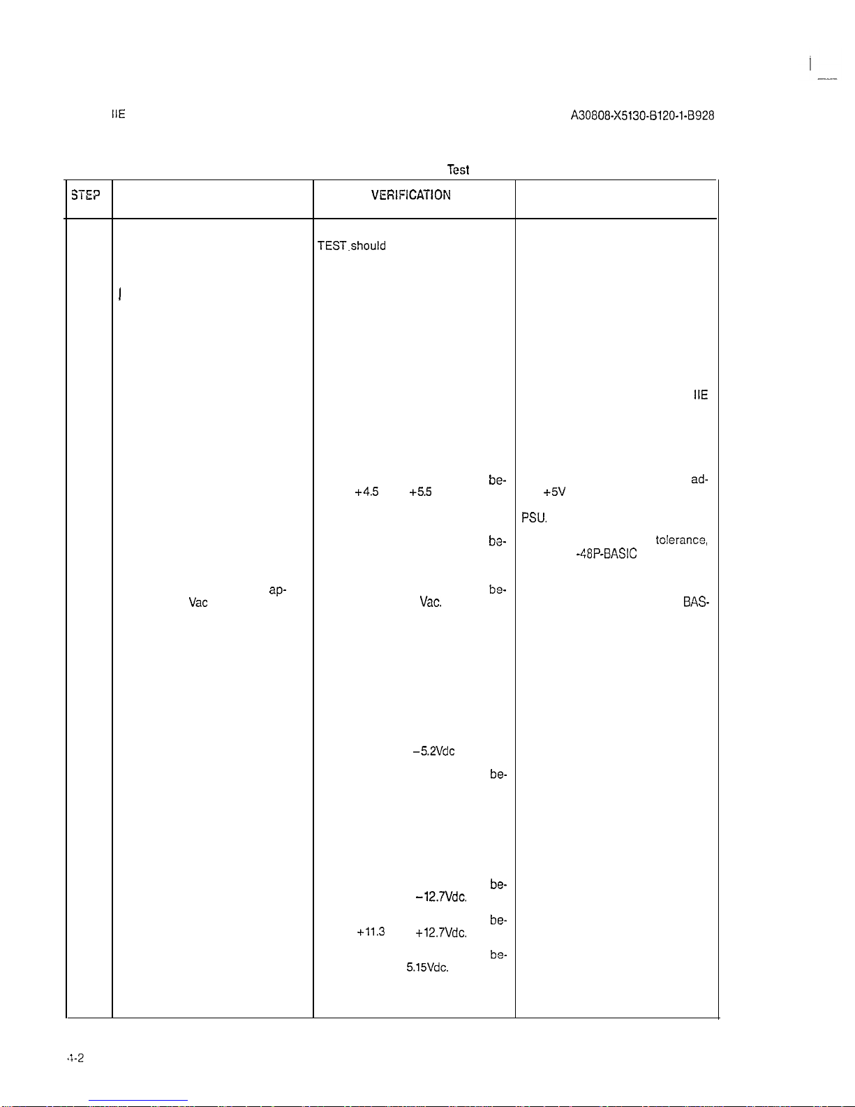
Table 4.00 Power-Up/Output Voltage
Test
(Continued)
SE?
PROCEDURE
VEfiIFICATION
IF VERIFICATION
IS NOT OBTAINED
c) On the PSU, place the circuit
The red LED designated BATTERY If the red LED remains extinguished,
breaker designated BASIC PS
TEST.should
be steadily lit. replace the MSM.
in the off (down) position.
The red BATTERY TEST LED should
1
d) On the PSU, place the circuit If the red LED remains steadily lit,
breaker designated BASIC PS be extinguished. either the cabinet ac power cord is
to the on (up) position.
not connected to the commercial ac
power receptacle or a local ac power failure has occurred.
7
Set digital multimeter to appropriate
NOTE
dc voltage scale for the following If further troubleshooting information
tests.
is required during these testing
procedures, refer to SATURN
IIE
EPABX Maintenance and
Troubleshooting Practice.
8A
To measure the unloaded basic shelf
input voltages, proceed as follows:
a) On basic backplane shown in
Voltage measured should read
be-
If reading is not within tolerance,
ad-
Figure 4.00, take reading be- tween
+4.5
and
+5.5
Vdc. just
+5V
ADJUST potentiometer on
tween terminal El, E2, E3 or PSU. If still out-of-tolerance replace
E4 and ground.
PSU.
b) On basic backplane connector
Voltage measured should read
bo-
If reading is not within
to!erance,
J46, shown in Figure 4.00, take
tween -43 and -53Vdc.
check the
-48P-BASIC
fuse in PSU.
readings beiween pins 2 and 3. If fuse is good, replace -48PSO.
c) Set digital multimeter to
ap-
Voltage measured should be
be-
If the voltage is not present, check
propriate
Vat
scale and take
tween 75 and 100
Vat.
and replace RGEN fuse or RAC
BAS-
reading between pins 1 and 2 IC fuse on PSU. If fuses are good,
of J46.
replace RGEN PCB. If voltage still not
present, replace PSU.
d) Set digital multimeter to appropri-
ate Vdc scale and take readings
between the following pins on
basic backplane connector J47
(shown in Figure 4.00):
1) Pins 1 and 3.
2) Pins 2 and 3.
Voltage measured should be be-
If reading is not within tolerance,
tween -4.9 and
-5.2Vdc
replace the PSU.
Voltage measured should be
be-
If reading is not within tolerance,
tween -43 and -53Vdc check the -488 BASIC fuse on PSU.
If the fuse is good, replace -48PS0.
e) On basic backplane connector
J48, shown in Figure 4.00, take
readings between the following
pins:
1) Pins 1 and 4.
2) Pin 2 or 3 and pin 4.
3) Pins 4 and 5.
Voltage measured should read
be-
If reading is not within tolerance,
tween -11.3 and
-12.7Vdc.
replace the PSU.
Voltage measured should be
be-
If reading is not within tolerance,
tween
+11.3
and
+12.7Vdc.
replace the PSU.
Voltage measured should be
be-
If reading is not within tolerance,
tween 4.85 and
5.15Vdc.
check that J16 on the rear panel of
the PSU is strapped to the MSM terminal. If the strap is in place, replace
the MSM.
I
-
SATURN
IIE
EPABX
Installation Test Procedures
A3G808-X5130-B120-1-B928
Issue 1, May 1986
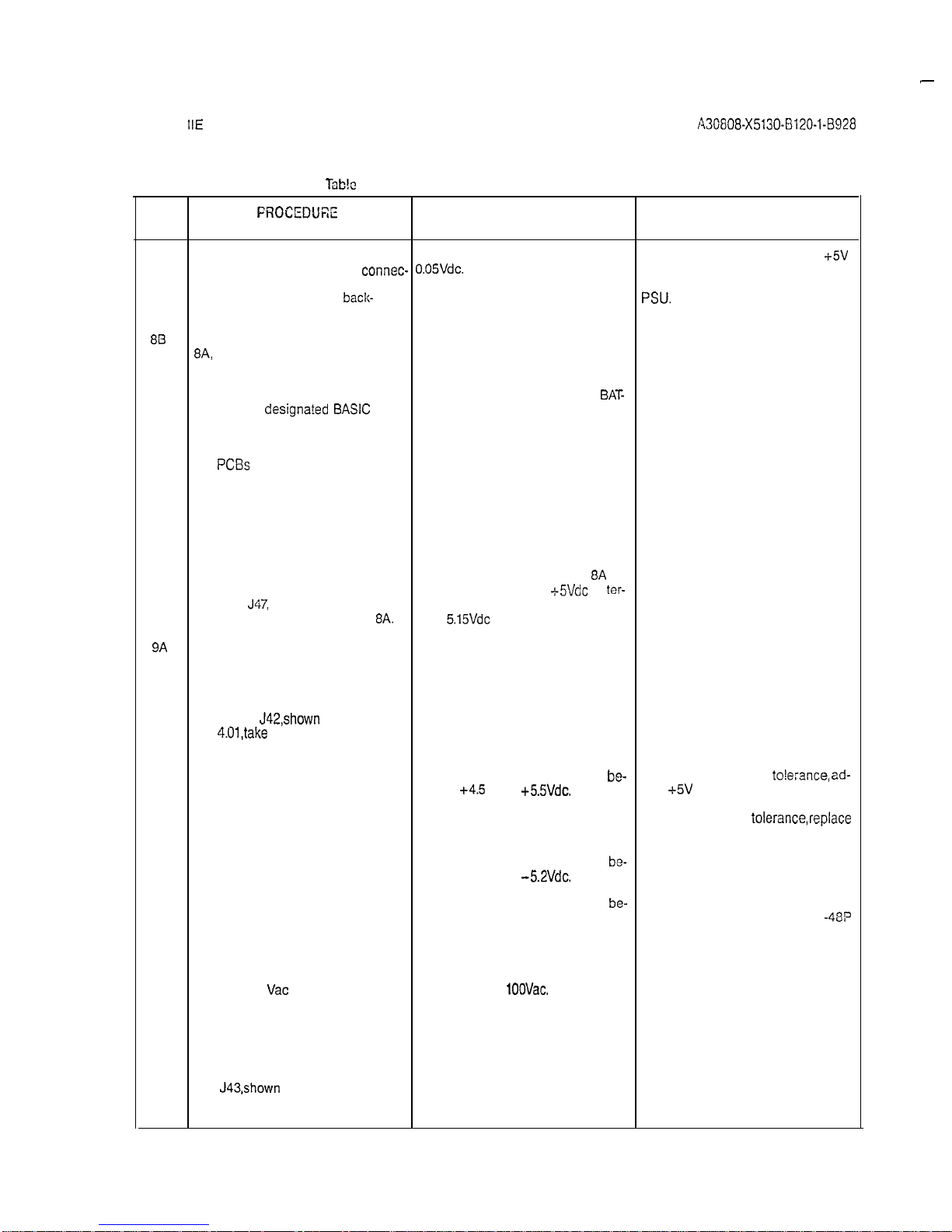
lbb!c
4.00 Power-Up/Output Voltage Test (Continued)
STEP
FROCEDUEE
VERIFICATION IF VERIFICATION
IS NOT OBTAINED
.
f) Connect positive lead of digital Voltage measured should read + If reading is not 0.05 Vdc, adjust
+5V
multimeter to pin 5 of
connec- 0.05Vdc.
ADJUST potentiometer on PSU. If
tor J48 and negative lead to
adjustment is not effective, replace
terminal El on basic
back-
PSU.
plane. (Refer to Figure 4.00.)
813
After satisfactorily completing step
8A,
proceed as follows to measure
the loaded basic shelf input voltages.
a) On the PSU, place the circuit The MSM red LED designated
BAT-
breaker
designa?ed BASIC
PS TERY TEST should be steadily lit.
in the off (down) position.
b) Plug all previously extracted
PCBs
on the basic shelf into
their respective backplane
connectors.
c) On the PSU, place the circuit
The MSM red LED designated BATbreaker designated BASIC PS TERY TEST should be extinguished.
in the on (up) position.
d) Repeat measuring procedures Same verification as in steps 8A a)
on basic backplane connectors
through e), except that
-t-S!/&
at
ter-
J46,
J47,
J48 and terminals
minal El should read between 4.85
El-E4 as indicated in step
8A.
and
5.15Vdc
under load.
9A
To measure the unloaded LTU shelf
input voltages (if applicable), proceed
as follows:
a) On the LTU backplane con-
nector
J42,shown
in Figure
4.01,take
a reading between
the following pins:
1) Pins 1 and 3.
Voltage measured should be
be-
If reading is not within
to!e:ance, ad-
tween
+4.5
and
+5.5Vdc.
just
+5V
ADJUST potentiometer on
LTUPS. If the adjustment does not
bring voltage into
tolerance,replace
LTUPS.
2) Pins 3 and 5.
3) Pins 3 and 4.
Voltages measured should be
be-
If reading is not within tolerance,
tween -4.9 and
-5.2Vdc.
replace appropriate LTUPS.
Voltage measured should be
be-
If reading does not coincide with
tween -43 and -53Vdc.
verification reading, check the
-48P
LTU fuse on PSU. If fuse is good,
replace -48PS0.
4) Set digital multimeter to
read
Vat
and connect be-
tween pins 2 and 3.
Voltage measured should be be- If voltage is not present,
tween 75 and
1OOVac.
check/replace RGEN fuse or RAC
LTUO fuse on PSU. If fuses are good,
replace PSU.
b) Set digital multimeter to ap-
propriate Vdc scale.
C) On LTU backplane connector
J43,shown
in Figure 4.01, take
a reading between the following pins:
4-3
 Loading...