

Siemens MT SAS Series, SAS61.33U, SAS61.03U, Powermite 599 Technical Instructions
Powermite 599
Technical Instructions
MT Series SAS Electronic
Valve Actuator 24 Vac or 24 Vdc,
Proportional Control
Document No. 155-682
January 19, 2016
Description
Features
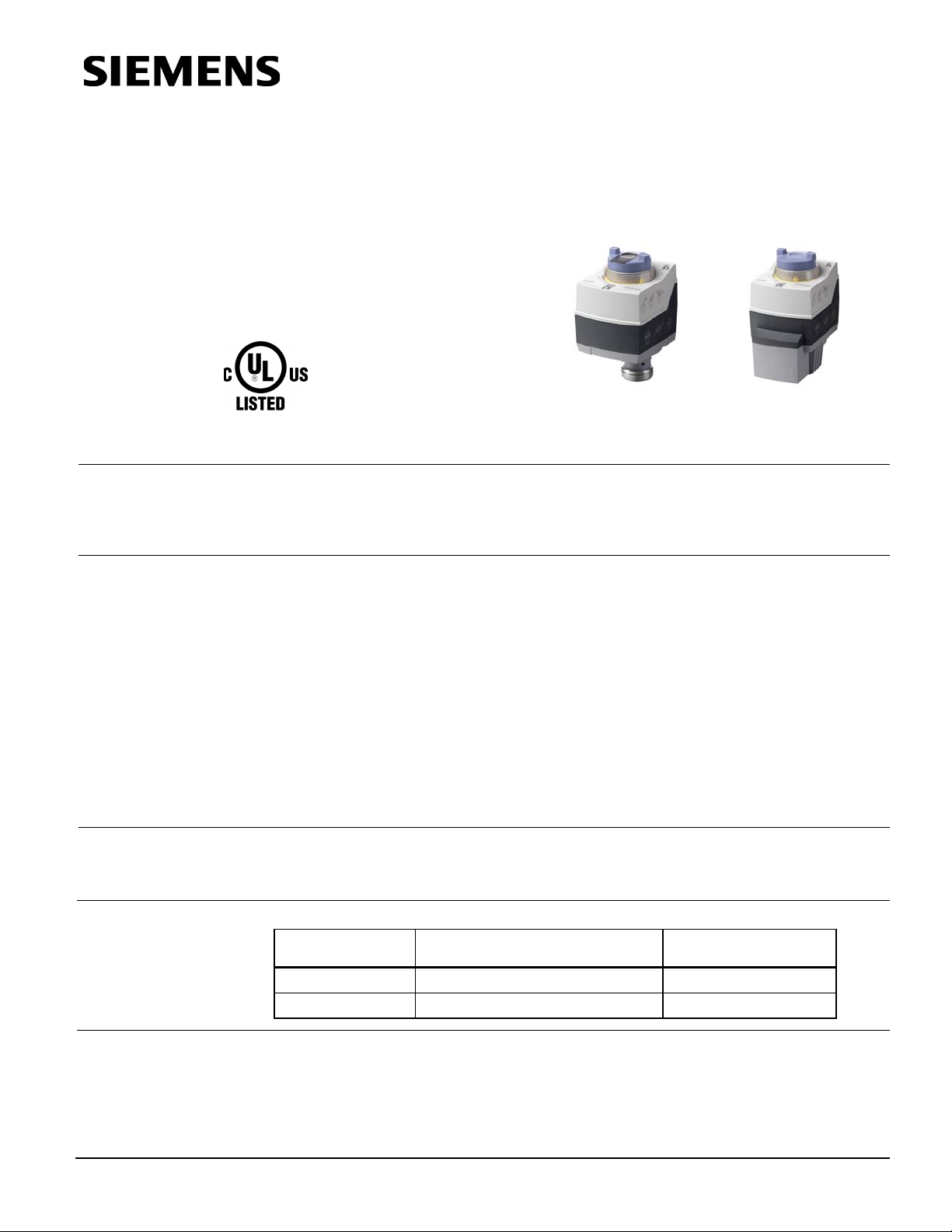
SAS61.03U
The Powermite 599 MT Series SAS Electronic Valve Actuator requires a 24 Vac or
24 Vdc supply and receives a 0 to 10 Vdc or a 4 to 20 mA control signal to proportionally
control a valve. This actuator is designed to work with Powermite 599 MT Series
terminal unit valve with a 7/32-inch (5.5 mm) stroke.
• Maintenance-free with reversible motor.
• Position indicator.
• UL listed for plenum installations.
• 0 to 10V or 4 to 20 mA.
• LED status indicator.
• Auto calibration
• Position output signal 0 to 10 Vdc.
• Manual positioning knob with stroke indication allows for repositioning.
• Mechanical spring returns the valve to its normal (fail-safe) position in power-off
conditions (SAS61.33U Actuator only).
SAS61.33U
Application
Product Numbers
Ordering
Information
For use in small to medium HVAC installations with Powermite 599 Series terminal unit
valves with a 7/32-inch (5.5 mm) stroke requiring a minimum of 90 pounds force (400N).
They can be used in liquid and low pressure steam service applications.
Product Number Actuator type Actuator Prefix Code
SAS61.03U Non-Spring Return (Fail-in-place) 364
SAS61.33U Spring Return (Fail-safe) 365
To order a complete valve plus actuator assembly from the factory, combine the
actuator prefix code with the suffix of the valve product number. See TB 251 Powermite
599 Series MT Series Terminal Unit Valve and Actuator Assembly Selections Technical
Bulletin (155-306P25) for selection procedures.
To order an actuator only, use the product number in Table 1.
Table 1. Ordering Information.
Siemens Industry, Inc.

Technical Instructions Powermite 599 Series MT Series SAS Electronic Valve Actuator 24V Proportional Control
Running time
UL UL873
Ambient temperature
Document No. 155-682
January 19, 2016
Specifications
Power Requirements
Control Characteri stics
Operating voltage 24 Vac ± 20%, 24 Vdc, + 20%, -15%
Frequency 45 to 65 Hz
Power supply Earth ground isolating, Class 2,
24V transformer, 100 VA max.
Power consumption - running
SAS61.03U 5.3 VA
SAS61.33U 5.9 VA
Terminal
Designation
Y Control Signal 0 to 10 Vdc, 4 to 20 mA
Current draw ≤0.1 mA for 0 to 10 Vdc control
4 to 20 mA ± 1% for 4 to 20 mA control
Input impedance >100K ohms
U Position feedback
Voltage 0 to 10 Vdc ± 1%
Load impedence >10K Ω res.
Current load 1 mA max.
Z Forced control
Resistance 0 to 1000Ω, stroke proportional to R
Z connected to G Max. stroke 100%
Z connected to G0 Min. stroke 0%
Voltage Max. 24 Vac to 20%,
Max 24 Vdc+20%,-15%
Current draw ≤0.1 mA
Functional Operation
Agency Approvals
Environmental
Conditions
Physical Characteristics
at 60 Hz 30 seconds
Spring return (SAS61.33U only) <14 seconds
Nominal stroke 7/32-inch (5.5 mm)
Nominal Force 90 lbs. (400N)
Spring return (SAS61.33U only) Mechanical spring
cUL Certified to CSA C22.2 No. 24-93
Operation 23°F to 131°F (–5°C to 55°C)
Transport and storage –13°F to 158°F (–25°C to 70°C)
Humidity <95% rh
Max. permissible media temperature in valve 34°F to 248°F (1°C to 120°C)
Conduit opening Knockouts for standard 1/2-inch
conduit connector
Weight
SAS61.03U 0.9 lbs. (0.4 kg)
SAS61.33U 1.5 lbs. (0.68 kg)
Dimensions See Figure 4 and Figure 5.
Page 2 Siemens Industry, Inc.
 Loading...