

Siemens SAS61.03U,SAS61.33U Installation Instructions Manual
Installation Instructions
SAS61 Series Electronic Valve Actuators
WARNING:
WARNING:
in the valve to drop.
Product Descript ion
Document No. 129-612
January 19, 2016
The SAS actuators require a 24 Vac or 24 Vdc, Class
2, supply and a 0 to 10 Vdc or 4 to 20 mA signal to
control Powermite 599 Series terminal unit valves with
7/32-inch (5.5 mm) stroke. In the SAS61.33U, a
mechanical spring returns the valve to its normal
position when there is no power supply.
Warning/Caution Nota t ions
Personal injury/loss of life may
WARNING:
CAUTION:
occur if you do not perform a
procedure as specified.
Equipment damage, or loss of
data may occur if you do not
follow the procedures as
specified.
Product Numbers
SAS61.03U – Non-spring Return (Fail-in-place)
actuator
SAS61.33U – Spring Return (Fail-safe) actuator
Required Tools
If mounting the actuator to a valve
already in line, either close the shut-off
valves in the piping (upstream first,
then downstream) or switch off the
pump to allow the differential pressure
Mounting
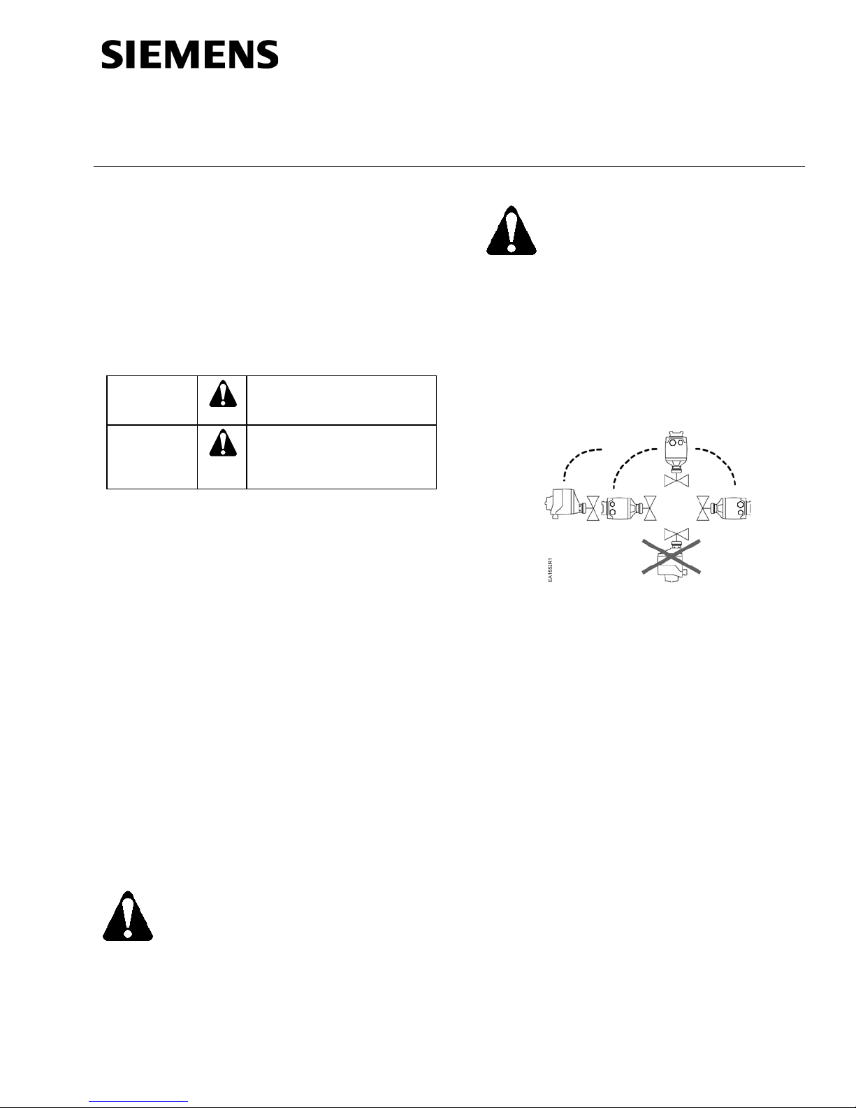
Figure 1 shows acceptable actuator mounting positions
for water applications. The recommended mounting
position of the actuator for low pressure steam
applications is between 45° and horizontal.
Figure 1. Acceptable Mounting Positions.
Installation
• #2 Phillips or flat-blade screwdriver
• Flat blade calibration screwdriver (3 mm) for
wiring connections
• Wire cutter/stripper
If you are mounting an actuator on a new valve, begin
with the instructions, Mounting an Actuator to a Valve.
Remove Actuator from Valve
1. Remove actuator cover screws using either a
Estimated Installation Time
• 12 minutes for wiring a factory-installed
actuator.
• 30 minutes for field replacement of an
actuator.
Prerequisites
Disconnect the controller power before
replacing the actuator.
Item Number: 129-612, Rev. AA Page 1 of 3
2. Identify and disconnect wires.
3. Replace actuator cover. Use cover screws to
4. Loosen coupling piece.
5. Remove actuator from valve.
No. 2 Phillips or a No. 2 flat-blade screwdriver and
detach actuator cover.
secure actuator cover in place.
Document No: 129-612
WARNING:
CAUTIONS:
Installation Instructions
January 19, 2016
Mounting an Actuator to a Valve
1. If you are attaching the actuator to a new valve,
remove the protective plastic cap from the valve
stem.
2. On the SAS61.03U Actuator, turn the manualpositioning knob counterclockwise to its end
point.
3. Place the actuator on the valve.
4. Hand-tighten the coupling piece.
5. Use either a Phillips head screwdriver or a flatblade screwdriver to remove the actuator cover
for access to the terminal block.
6. Attach wires. See Wiring and Start-Up.
7. Place the cover on the actuator.
8. Fasten the cover with the screws.
Wiring
All wiring must conform to NEC and local codes and
regulations.
Use earth ground isolating, step-down Class 2
transformers. Do not use auto transformers.
Determine the supply transformer rating by adding the
total VA of all actuators used. The maximum rating for
Class 2 step-down transformer is 100 VA. It is
recommended that no more than 10 actuators be
powered by one transformer.
Terminal connection G is 24 Vac HOT, not
ground.
• G0 and G must be properly wired for
correct function and full life of the
actuator.
• If the actuator makes a buzzing noise
upon reaching setpoint, G and G0 are
improperly wired and should be
reversed.
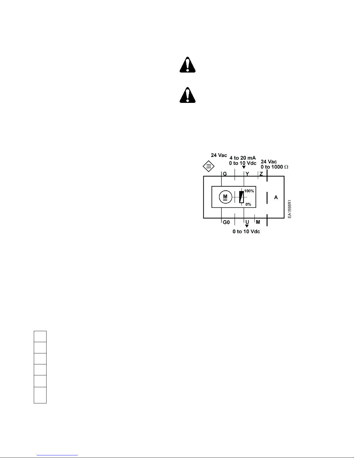
Figure 3. Wiring Diagram.
The diagram shows all possible connections. The
application determines which connections are used.
1. Remove actuator cover screws using either a
Start-Up
No. 2 Phillips or a No. 2 flat-blade screwdriver
and detach actuator cover.
2. Access terminal block and attach wires per
Figure 2.
3. Replace actuator cover. Use cover screws to
secure actuator cover in place.
G0
Neutral (-)
G
Hot (+)
Y
Positioning signal for 0 to 10 Vdc/4 to 20 mA
M
Measuring neutral
Position feedback 0 t o 10 V dc
U
Positioning signal forced control AC/DC ≤ 24V,
Z
0 to 1000 Ω
Figure 2. Terminal Connections.
The valve body (normally open or normally closed)
determines the action of the complete valve/actuator
assembly.
Troubleshooting
• Check wiring for proper connections and secure
attachments.
• Check for adequate power supply.
References
Powermite 599 MT Series SAS Electronic Valve
Actuators, 24 Vac or 24 Vdc, Proportional Control
Technical Instructions (155-682).
Page 2 of 3 Siemens Industry, Inc.
 Loading...