

Siemens SAP 20 Installation Instructions Manual
s
External power supply unit
SAP 20
SLP 20 UK
20 800 225.0-010
Installation instructions
1. Product description
The SAP 20 is a power supply unit suitable for an E-Bus and
has an output voltage of 12 V at a maximum of 2.3 A. The
housing offers space for 7 type SMT 11 (transponder) or SMR
11 (isolator/amplifi er) circuit boards and for a 12 V, 24 Ah
battery. At least one SMT 11 must be fi tted to use the cover
tamper contact.
2. Supply package
The SAP 20 UK package contains the following:
- One SAP 20 power supply unit.
- One set (4 off) of spacers.
- One SLP 20 UK language kit complete with :
- Installation instructions.
- One wiring diagram.
3. Mounting instructions
The SAP 20 external power supply unit is designed for mounting in dry indoor rooms. It must not be exposed to dripping
or splashing water.
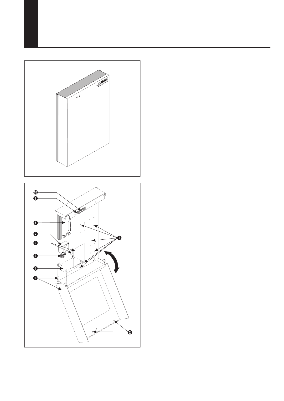
3.1 Open cover (Fig. 1)
1 - Slacken cover screw W.
2 - Remove cover.
3.2 Product overview (Fig. 1)
- Housing E.
- Power supply assembly circuit board SMP 20 I.
- Transformer SMU 31 U.
- Mains supply terminals T with fuse.
- Eye O for sealing.
- Tamper contact P.
- Cable inlet Y.
- Mounting holes for SMT 11 or SMR 11 circuit boards
(optional) Q.
- Space for battery R.
- Cover screws W.
Fig. 1
8AA10427 - F0 - 09/04/2003 - UK - SNR 557773.0-001
1
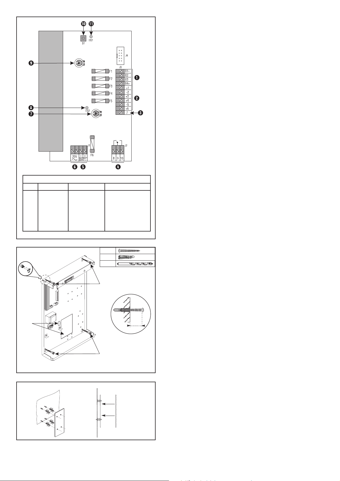
Fuses
No. Terminal Function Type
F1 B4+ E-Bus F2AL
F2 +1 +12V F2AL
F3 +3 +12V F2AL
F4 +4 +12V F2AL
F5 +6 +12V F2AL
F6 + Batt. Battery T2AL
Fig. 2
3.2.1 Power supply unit circuit board SMP 20 (Fig. 2)
- Transformer terminal Y 20V, 50Hz.
- Relay R which can be programmed from the central
control unit.
- Four +12 V voltage outputs W (+1, +3, +4, +6) each of
which is protected by a fuse (F2 to F5).
- Output E for mains supply indication (not fused).
- E-Bus connection to central control unit Q (B1-, B2, B3,
B4+). B4+ is protected by fuse F1.
- Pre-wired battery terminal T is protected by fuse F6.
- Address key P.
- LED { fl ashes if the E-Bus communication is correct.
- LED I for mains supply indication.
- The adjustment of potentiometer U ,O must not be disturbed.
A
W
Fig. 3
4,5 x 45
Ø 6 mm
Q
Q
3.3 Fit housing (Fig. 3)
S6
1,5 cm
B
1 - Mark the drilling position for the four mounting holes Q.
2 - Drill the holes and insert plugs.
3 - Screw in the screws leaving approximately 1.5 cm
proud (Fig. 3B).
4 - From the back, snap the spacers into the slots provided
at the four mounting holes (Fig. 3A).
5 - Pass the connecting cable through the opening W provi
ded and hang the housing base on the screws
6 - Tighten the mounting screws.
3.4 Fit circuit boards SMT 11 or SMR 11 "optional"
(Fig.4)
1 - Engage the mounting studs (provided with the circuit
boards) in the holes provided (Fig. 4A).
2 - Fit circuit boards (Fig. 4B).
Fig. 4
A
B
2
 Loading...