

Siemens SAP14 Installation Instructions Manual
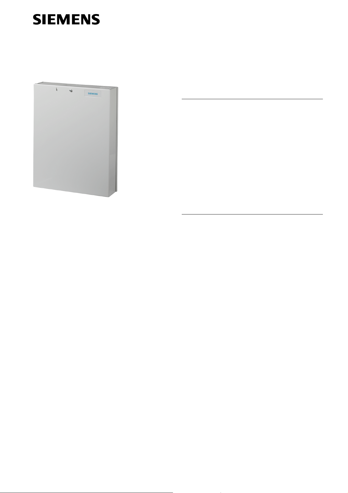
SAP14
External power supply
Installation instructions
Product description
The SAP14 is a power supply unit suitable for an E-Bus
and has an output voltage of 12 V at a maximum of 1.3
A. The housing offers space for four type SMT12 (transponder) and for a battery of up to 12 V, 17 Ah for VdS
applications or up to 12 V, 17 Ah for non-VdS
applications. At least one SMT12 must be fitted to use
the cover tamper contact.
Security
z Keep this document for later reference.
z Also follow the country-specific safety standards or
regulations for project planning, operating and disposing of the product.
z The device is always to be disconnected from the
mains or battery prior to performing maintenance work
or installing additional devices.
Liability claim
z Do not connect the device if components are missing
or damaged.
z Only make changes to the unit that are explicitly
mentioned in this document or which have been
approved by the manufacturer.
z Use only spare parts and accessories approved by the
manufacturer.
Damages due to a inappropriate mounting location
z Observe the environmental requirements recom-
mended by the manufacturer.
z Do not operate the unit in areas exposed to extreme
dust formation, moisture, vibration or flammable
gases.
Building Technologies
Fire Safety & Security Products

Risk of electrical shock
z Ensure that the connection is secure and the circuit
breaker to the supply circuit is easily accessible when
operating the unit (e.g. fuse up to 16 A).
z Do not connect any external consumers to the fuse.
z Grounding has to adhere to the respective safety
regulations.
Device damage due to overvoltage
z Connect the unit only to current sources with the
specified voltage. Information on the power supply is
available on the power supply unit / rating plate.
Risk of panic reactions
z Prior to testing the system, make sure all important
persons involved and supporting authorities are
informed.
z To avoid panic, all involved should be informed prior to
testing alarm facilities.
Danger of explosion
z Make sure that the battery poles do not short circuit.
z Please pay attention to battery polarity.
z Always fasten the battery in place with the holder
intended for this purpose.
Technical data
Mains voltage 230 V AC, + 10 % / -15 %, 50 Hz
Power intake max. 34 VA (at 230 V AC)
Mains supply fuse 160 mA T (Mains power)
Output voltage/current 13.7 V DC / 1.3 A
Max. ripple at 1.3 A 60 mV
Relay, single-pole
changeover
Battery type according to
VdS
Battery type not according
to VdS
Operating temperature 0 to 40 °C
Steel housing 1.5 mm
Dimensions (W x H x D) 303 x 400 x 87.5 mm
Protection rating IP30
Environmental class II
Weight without battery 5.5 kg
48 V / 5 A
YUASA, Type NP7-12
(12 V / 7.2 Ah) recommended
YUASA, Type NP17-12
(12 V / 17 Ah) recommended
Package contents
The SAP 14 package contains the following:
z One SAP14 power supply unit
z One battery holder
z One set (4 units) of spacers
z Installation instructions (de, en, fr, it)
z Terminal connection diagram
2
Siemens Building Technologies
Fire Safety & Security Products 01.2009
1
2
9
10
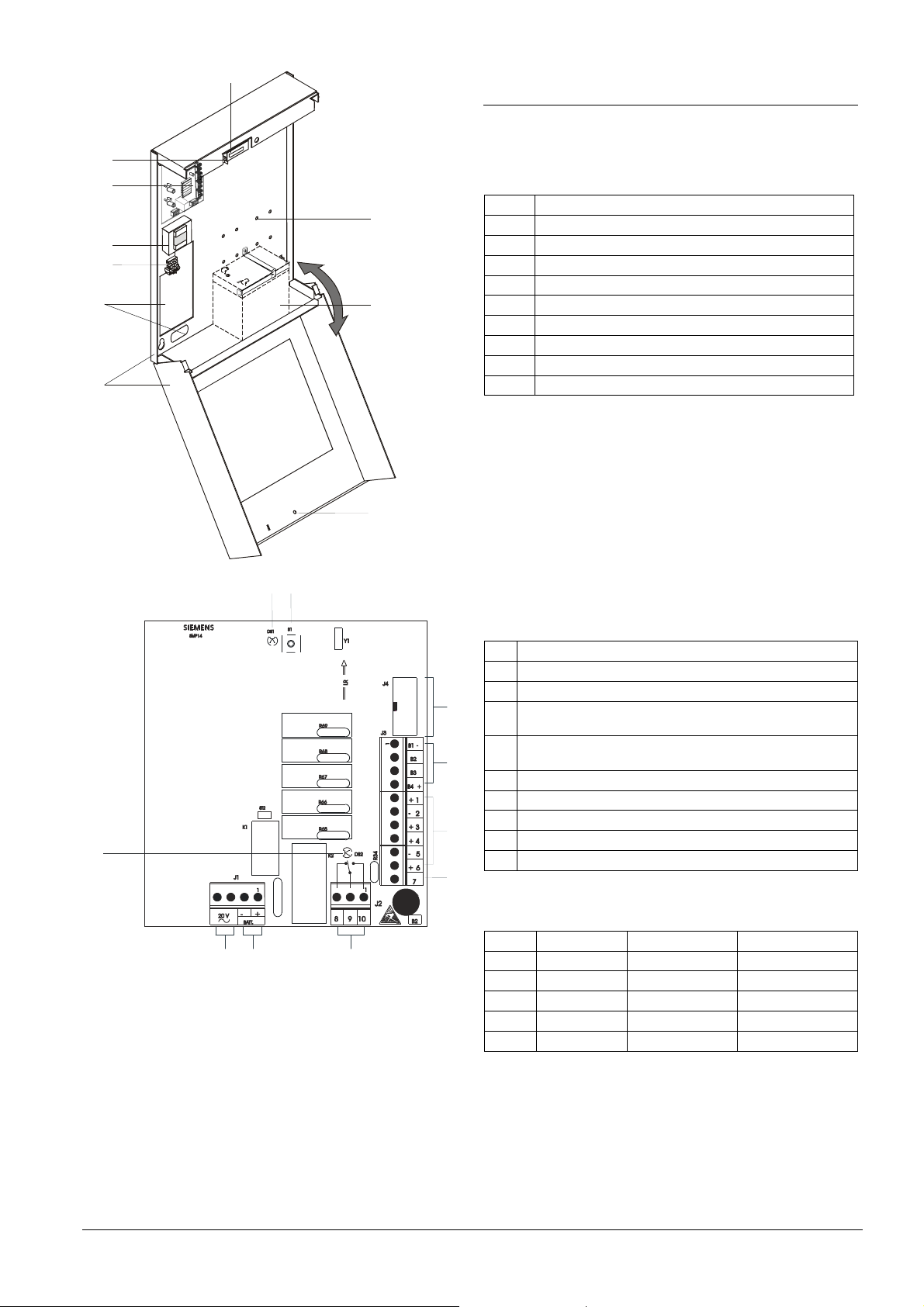
Assembly
The SAP14 external power supply unit is designed for
9
8
1
7
6
5
2
4
mounting in dry indoor rooms. It must not be exposed to
dripping or splashing water.
1 Mounting holes for relay boards (optional)
2 Space for battery up to 12 V / 17 Ah
3 Cover screw
4 Housing
5 Cable inlets
6 Mains supply terminals with F7 fuse.
7 Transformer SMU22
8 Power supply assembly circuit board SMP14
9 Eye for sealing.
10 Tamper contact
Open cover
1. Loosen cover screw (3) Fig. 1
2. Remove cover
Fig. 1
10
Fig. 2
3
Power supply assembly circuit board SMP14
1 LED flashes when E-bus communication is intact
2 Address button
3 Not used
3
F1
(B4+)
F2
(+1)
F3
(+3)
F4
(+4)
F5
(+6)
R45
8
7
4 E-Bus connection to burglary detection control unit
(B1-, B2, B3, B4+); B4+ is secured by F1.
5 4 outputs +12 V (+1, +3, +4, +6), which are each secured
4
5
6
with a fuse (F2 to F5).
6 Output for mains supply indication (not fused).
7 1 relay output (1 pin 48 V / 5 A switching current)
8 Pre-wired battery terminal; protected by R45
9 Transformer terminal 20 V, 50 Hz
10 LED for mains supply indication
Fuses
No. Connection Function Type
F1 B4+ E-bus (12 V DC) F2A F 250 V
F2 +1 +12 V DC F2A F 250 V
F3 +3 +12 V DC F2A F 250 V
F4 +4 +12 V DC F2A F 250 V
F5 +6 +12 V DC F2A F 250 V
3
Siemens Building Technologies
Fire Safety & Security Products 01.2009
 Loading...