

Page 1

Contents
SIMATIC
S5-135U/155U
System Manual
This manual has the
order number:
Notes on Using this Manual
and on the CE Symbol
Centralized and Distributed
Configuration of a Programmable Controller
Installation Guidelines
Central Controllers and
Expansion Units
Power Supply Units
CPUs, Memory Cards,
Memory Submodules,
Interface Submodules
Multiprocessor Operation/
Coordinators
Interface Modules
1
2
3
4
5
6
7
6ES5998-0SH21
12/98
C79000-G8576-C199
Release 06
Digital Input/Output Modules
Analog Input/Output Modules
Monitoring Module
Connector Assignments
Appendices
Appendix
Guidelines for Handling
Electrostatically-Sensitive
Devices (ESD)
Index
8
9
10
11
A
B
Page 2

Safety Guidelines
!
#$.()0'*)/$).)*/$ .2#$#4*0.#*0'*. -1 /* ).0- 4*0-*2)+ -.*)'.! /4.2 ''./*
+-*/ //# +-*0/)*)) / ,0$+( )/# . )*/$ .- #$"#'$"#/ $)/# ()0'42-)$)"
/-$)"' )- (-& .!*''*2.*-$)"/*/# ' 1 '*!)" -
Warning
$)$/ ./#/ /#. 1 - + -.*)'$)%0-4*-.0./)/$'+-*+ -/4(" )- .0'/$!+-*+ -+- 0/$*).)*//& )
Note
-2.4*0-// )/$*)/*+-/$0'-'4$(+*-/)/$)!*-(/$*)*)/# +-*0/#)'$)"/# +-*0/*-/*+-/$0'+-/*!/# *0( )//$*)
Qualified Personnel
Correct Usage
!
!
!
# 1$ .4./ ((4*)'4 . /0+)*+ -/ $)*)%0)/$*)2$/#/#$.()0'
)'4 .#*0' ''*2 /*$)./'')2*-&*)/#$. ,0$+( )/0'$!$ + -.*). !$) .+ -.*).2#*- 0/#*-$5 /**(($..$*)/*"-*0))/*/"$-0$/. ,0$+( )/).4.6
/ (.$)*-) 2$/# ./'$.# .! /4+-/$ .)./)-.
*/ /# !*''*2$)"
Warning
#$. 1$ )$/.*(+*) )/.(4*)'4 0. !*-/# ++'$/$*). .-$ $)/# /'*"*-/# / #)$'
.-$+/$*))*)'4$)*)) /$*)2$/# 1$ .*-*(+*) )/.!-*(*/# -()0!/0- -.2#$##1 )
++-*1 *-- *(( ) 4$ ( ).
#$.+-*0/)*)'4!0)/$*)*-- /'4).! '4$!$/$./-).+*-/ ./*- . /0+)$)./'' *-- /'4)
*+ -/ )($)/$) .- *(( )
Caution
!
)" -*! 3+'*.$*)$!// -4$.$)*-- /'4- +' +' *)'42$/#.( *- ,0$1' )//4+
- *(( ) 4/# ()0!/0- -$.+*. *!0. // -$ .*-$)"/*/# ()0!/0- -.$)./-0/$*).
Warning
6
Trademarks
The reproduction, transmission or use of this document or its
contents is not permitted without express written authority.
Offenders will be liable for damages. All rights, including rights
created by patent grant or registration of a utility model or design, are
reserved.
$ ( ).
Bereich Automatisierungs- und Antriebstechnik
Geaschaeftsgebiet Industrie Automatisierungssysteme
Postfach 4848,D-90327 Nuernberg
R)R)R - - "$./ - /- (-&.*!
#$-+-/$ .0.$)"!*-/# $-*2)+0-+*. .)4*/# -)( .$)/#$.*0( )/2#$#- ! -/*/- (-&.($"#/
$)!-$)" 0+*)/# -$"#/.*!/# /- (-&*2) -.
Siemens Aktiengesellschaft
C7-633, C7-634 Control Systems
Disclaimer of LiabilityCopyright E Siemens AG 1993 All rights reserved
We have checked the contents of this manual for agreement with the
hardware and software described. Since deviations cannot be
precluded entirely, we cannot guarantee full agreement. However,
the data in this manual are reviewed regularly and any necessary
corrections included in subsequent editions. Suggestions for
improvement are welcomed.
E Siemens AG 1993
0% //*#)" 2$/#*0/+-$*-)*/$
6ES5998-0SH21
Page 3

Contents
1 Notes on Using this Manual and on the CE Symbol 1-1. . . . . . . . . . . . . . . . . . . . . . .
Notes on Using this Manual 1-1. . . . . . . . . . . . . . . . . . . . . . . . . . . . . . . . . . . . . . .
Notes on the CE Symbol 1-4. . . . . . . . . . . . . . . . . . . . . . . . . . . . . . . . . . . . . . . . .
Notes for Machine Manufacturers 1-6. . . . . . . . . . . . . . . . . . . . . . . . . . . . . . . . . .
Safety Notes 1-7. . . . . . . . . . . . . . . . . . . . . . . . . . . . . . . . . . . . . . . . . . . . . . . . . . . .
2 Centralized and Distributed Configuration of a Programmable Controller 2-1. . .
2.1 Application 2-2. . . . . . . . . . . . . . . . . . . . . . . . . . . . . . . . . . . . . . . . . . . . . . . . . . . . .
2.2 Centralized and Distributed Configuration 2-3. . . . . . . . . . . . . . . . . . . . . . . . . . .
2.2.1 Installing a PLC with Centralized Configuration 2-4. . . . . . . . . . . . . . . . . . . . . .
2.2.2 Installing a PLC with Distributed Configuration 2-5. . . . . . . . . . . . . . . . . . . . . . .
2.3 Examples 2-6. . . . . . . . . . . . . . . . . . . . . . . . . . . . . . . . . . . . . . . . . . . . . . . . . . . . . .
3 Installation Guidelines 3-1. . . . . . . . . . . . . . . . . . . . . . . . . . . . . . . . . . . . . . . . . . . . . . . . . .
3.1 Principles of Installation of Systems for EMC 3-2. . . . . . . . . . . . . . . . . . . . . . . .
3.1.1 Overview of Possible Types of Interference 3-2. . . . . . . . . . . . . . . . . . . . . . . . .
3.1.2 The Most Important Basic Rules for Ensuring EMC 3-6. . . . . . . . . . . . . . . . . .
3.2 Installation of Programmable Controllers for EMC 3-8. . . . . . . . . . . . . . . . . . . .
3.2.1 Basic Rules for Assembling and Grounding the Inactive Metal
Parts 3-8. . . . . . . . . . . . . . . . . . . . . . . . . . . . . . . . . . . . . . . . . . . . . . . . . . . . . . . . . .
3.2.2 Example of Cabinet Assembly for EMC 3-9. . . . . . . . . . . . . . . . . . . . . . . . . . . . .
3.2.3 Example of Rack and Wall Mounting for EMC 3-11. . . . . . . . . . . . . . . . . . . . . . .
3.3 Wiring of Programmable Controllers for EMC 3-12. . . . . . . . . . . . . . . . . . . . . . .
3.3.1 Routing of Cables 3-12. . . . . . . . . . . . . . . . . . . . . . . . . . . . . . . . . . . . . . . . . . . . . . .
3.3.2 Equipotential Bonding 3-14. . . . . . . . . . . . . . . . . . . . . . . . . . . . . . . . . . . . . . . . . . . .
3.3.3 Shielding of Cables and Lines 3-15. . . . . . . . . . . . . . . . . . . . . . . . . . . . . . . . . . . . .
3.3.4 Special Measures for Interference-Free Operation 3-17. . . . . . . . . . . . . . . . . . .
3.3.5 Checklist for the Electromagnetically Compatible Installation
of Control Systems 3-19. . . . . . . . . . . . . . . . . . . . . . . . . . . . . . . . . . . . . . . . . . . . . .
3.4 Power Supplies for Programmable Controllers and I/Os 3-20. . . . . . . . . . . . . .
3.4.1 Power Supplies for Control Systems with SIMATIC S5 3-20. . . . . . . . . . . . . . .
3.4.2 Connecting the Programmable Controller and Load Power 3-21. . . . . . . . . . . .
3.4.3 Connecting Non-Floating or Floating Modules 3-26. . . . . . . . . . . . . . . . . . . . . . .
3.5 Interference-Free Installation of Centralized and Distributed
Interface Circuits 3-28. . . . . . . . . . . . . . . . . . . . . . . . . . . . . . . . . . . . . . . . . . . . . . . .
3.5.1 Interference-Free Installation of Centralized Interface Circuits 3-28. . . . . . . . .
3.5.2 Interference-Free Installation of Distributed Interface Circuits 3-28. . . . . . . . . .
3.6 Interference-Free Connection of Monitors 3-30. . . . . . . . . . . . . . . . . . . . . . . . . . .
System Manual
C79000-G8576-C199-06
iii
Page 4

Contents
3.6.1 Interference-Free Connection of a Monitor to the CP of the S5
Controller 3-30. . . . . . . . . . . . . . . . . . . . . . . . . . . . . . . . . . . . . . . . . . . . . . . . . . . . . .
3.6.2 Shielding and Grounding 3-31. . . . . . . . . . . . . . . . . . . . . . . . . . . . . . . . . . . . . . . . .
3.7 Selection and Installation of Cabinets with SIMATIC S5 3-33. . . . . . . . . . . . . . .
3.7.1 Types of Cabinet 3-34. . . . . . . . . . . . . . . . . . . . . . . . . . . . . . . . . . . . . . . . . . . . . . . .
3.7.2 Clearances in Cabinets 3-34. . . . . . . . . . . . . . . . . . . . . . . . . . . . . . . . . . . . . . . . . .
3.7.3 Removal of Power Dissipation from Cabinets 3-37. . . . . . . . . . . . . . . . . . . . . . . .
3.7.4 Examples for Determining the Type of Cabinet 3-38. . . . . . . . . . . . . . . . . . . . . .
3.7.5 Determining the Power Dissipation of Modules 3-39. . . . . . . . . . . . . . . . . . . . . .
4 Central Controllers and Expansion Units Power Supply Units 4-1. . . . . . . . . . . . .
4.1 S5-135U/155U Central Controller 4-2. . . . . . . . . . . . . . . . . . . . . . . . . . . . . . . . . .
4.1.1 Technical Description 4-2. . . . . . . . . . . . . . . . . . . . . . . . . . . . . . . . . . . . . . . . . . . .
4.1.2 Installation 4-6. . . . . . . . . . . . . . . . . . . . . . . . . . . . . . . . . . . . . . . . . . . . . . . . . . . . .
4.1.3 Startup 4-10. . . . . . . . . . . . . . . . . . . . . . . . . . . . . . . . . . . . . . . . . . . . . . . . . . . . . . . . .
4.1.4 Repair Guidelines 4-12. . . . . . . . . . . . . . . . . . . . . . . . . . . . . . . . . . . . . . . . . . . . . . .
4.1.5 Technical Specifications 4-13. . . . . . . . . . . . . . . . . . . . . . . . . . . . . . . . . . . . . . . . . .
4.2 Expansion Units 4-15. . . . . . . . . . . . . . . . . . . . . . . . . . . . . . . . . . . . . . . . . . . . . . . . .
4.2.1 Technical Description of the Expansion Units 4-16. . . . . . . . . . . . . . . . . . . . . . . .
4.2.2 Installing the Expansion Units 4-18. . . . . . . . . . . . . . . . . . . . . . . . . . . . . . . . . . . . .
4.2.3 Technical Specifications of the Expansion Units 4-18. . . . . . . . . . . . . . . . . . . . .
4.3 Power Supply Units 4-19. . . . . . . . . . . . . . . . . . . . . . . . . . . . . . . . . . . . . . . . . . . . . .
4.3.1 Product Overview 4-19. . . . . . . . . . . . . . . . . . . . . . . . . . . . . . . . . . . . . . . . . . . . . . .
4.3.2 Setting and Connecting the Power Supply Unit 4-23. . . . . . . . . . . . . . . . . . . . . .
4.3.3 Fault Indications/Fault Diagnostics 4-36. . . . . . . . . . . . . . . . . . . . . . . . . . . . . . . . .
4.3.4 Maintenance and Repairs 4-40. . . . . . . . . . . . . . . . . . . . . . . . . . . . . . . . . . . . . . . .
4.3.5 Description of Internal Sequences in the Power Supply Unit 4-49. . . . . . . . . . .
4.3.6 Technical Specifications of the Power Supply Units 4-51. . . . . . . . . . . . . . . . . .
4.4 6ES5 955-3NA12 Power Supply Unit 4-57. . . . . . . . . . . . . . . . . . . . . . . . . . . . . . .
4.4.1 Technical Description 4-57. . . . . . . . . . . . . . . . . . . . . . . . . . . . . . . . . . . . . . . . . . . .
4.4.2 Setting the Power Supply Unit 4-60. . . . . . . . . . . . . . . . . . . . . . . . . . . . . . . . . . . . .
4.4.3 Installation 4-63. . . . . . . . . . . . . . . . . . . . . . . . . . . . . . . . . . . . . . . . . . . . . . . . . . . . .
4.4.4 Operation 4-64. . . . . . . . . . . . . . . . . . . . . . . . . . . . . . . . . . . . . . . . . . . . . . . . . . . . . .
4.4.5 Maintenance 4-66. . . . . . . . . . . . . . . . . . . . . . . . . . . . . . . . . . . . . . . . . . . . . . . . . . . .
4.4.6 Technical Specifications 4-68. . . . . . . . . . . . . . . . . . . . . . . . . . . . . . . . . . . . . . . . . .
4.5 Fan Submodules 4-70. . . . . . . . . . . . . . . . . . . . . . . . . . . . . . . . . . . . . . . . . . . . . . . .
4.5.1 Technical Description 4-70. . . . . . . . . . . . . . . . . . . . . . . . . . . . . . . . . . . . . . . . . . . .
4.5.2 Setting and Connecting the Fan Submodule 4-72. . . . . . . . . . . . . . . . . . . . . . . .
4.5.3 Technical Specifications 4-74. . . . . . . . . . . . . . . . . . . . . . . . . . . . . . . . . . . . . . . . . .
5 CPUs, Memory Cards, Memory Submodules, Interface Submodules 5-1. . . . . . . .
5.1 CPU 948B -3UA13 or CPU 948B -3UA23 5-2. . . . . . . . . . . . . . . . . . . . . . . . . . .
5.1.1 Technical Description 5-2. . . . . . . . . . . . . . . . . . . . . . . . . . . . . . . . . . . . . . . . . . . .
5.1.2 Installation and Startup 5-3. . . . . . . . . . . . . . . . . . . . . . . . . . . . . . . . . . . . . . . . . . .
5.1.3 Interfaces of the CPU 948 5-13. . . . . . . . . . . . . . . . . . . . . . . . . . . . . . . . . . . . . . . .
5.1.4 Technical Specifications 5-15. . . . . . . . . . . . . . . . . . . . . . . . . . . . . . . . . . . . . . . . . .
5.2 CPU 948 5-17. . . . . . . . . . . . . . . . . . . . . . . . . . . . . . . . . . . . . . . . . . . . . . . . . . . . . . .
5.2.1 Technical Description 5-17. . . . . . . . . . . . . . . . . . . . . . . . . . . . . . . . . . . . . . . . . . . .
5.2.2 Installation and Startup 5-18. . . . . . . . . . . . . . . . . . . . . . . . . . . . . . . . . . . . . . . . . . .
iv
C79000-G8576-C199-06
System Manual
Page 5

Contents
5.2.3 Interfaces of the CPU 948 5-27. . . . . . . . . . . . . . . . . . . . . . . . . . . . . . . . . . . . . . . .
5.2.4 Technical Specifications 5-28. . . . . . . . . . . . . . . . . . . . . . . . . . . . . . . . . . . . . . . . . .
5.3 CPU 928B -3UB21 5-30. . . . . . . . . . . . . . . . . . . . . . . . . . . . . . . . . . . . . . . . . . . . . .
5.3.1 Technical Description 5-30. . . . . . . . . . . . . . . . . . . . . . . . . . . . . . . . . . . . . . . . . . . .
5.3.2 Installation and Startup 5-33. . . . . . . . . . . . . . . . . . . . . . . . . . . . . . . . . . . . . . . . . . .
5.3.3 Technical Specifications 5-40. . . . . . . . . . . . . . . . . . . . . . . . . . . . . . . . . . . . . . . . . .
5.4 CPU 928B 5-42. . . . . . . . . . . . . . . . . . . . . . . . . . . . . . . . . . . . . . . . . . . . . . . . . . . . . .
5.4.1 Technical Description 5-42. . . . . . . . . . . . . . . . . . . . . . . . . . . . . . . . . . . . . . . . . . . .
5.4.2 Installation and Startup 5-45. . . . . . . . . . . . . . . . . . . . . . . . . . . . . . . . . . . . . . . . . . .
5.4.3 Technical Specifications 5-52. . . . . . . . . . . . . . . . . . . . . . . . . . . . . . . . . . . . . . . . . .
5.5 CPU 928 -3UA21 5-54. . . . . . . . . . . . . . . . . . . . . . . . . . . . . . . . . . . . . . . . . . . . . . . .
5.5.1 Technical Description 5-54. . . . . . . . . . . . . . . . . . . . . . . . . . . . . . . . . . . . . . . . . . . .
5.5.2 Installation and Startup 5-56. . . . . . . . . . . . . . . . . . . . . . . . . . . . . . . . . . . . . . . . . . .
5.5.3 Technical Specifications 5-61. . . . . . . . . . . . . . . . . . . . . . . . . . . . . . . . . . . . . . . . . .
5.6 CPU 928 5-62. . . . . . . . . . . . . . . . . . . . . . . . . . . . . . . . . . . . . . . . . . . . . . . . . . . . . . .
5.6.1 Technical Description 5-62. . . . . . . . . . . . . . . . . . . . . . . . . . . . . . . . . . . . . . . . . . . .
5.6.2 Installation and Startup 5-64. . . . . . . . . . . . . . . . . . . . . . . . . . . . . . . . . . . . . . . . . . .
5.6.3 Technical Specifications 5-70. . . . . . . . . . . . . . . . . . . . . . . . . . . . . . . . . . . . . . . . . .
5.7 CPU 922 5-71. . . . . . . . . . . . . . . . . . . . . . . . . . . . . . . . . . . . . . . . . . . . . . . . . . . . . . .
5.7.1 Technical Description 5-71. . . . . . . . . . . . . . . . . . . . . . . . . . . . . . . . . . . . . . . . . . . .
5.7.2 Installation and Startup 5-73. . . . . . . . . . . . . . . . . . . . . . . . . . . . . . . . . . . . . . . . . . .
5.7.3 Technical Specifications 5-79. . . . . . . . . . . . . . . . . . . . . . . . . . . . . . . . . . . . . . . . . .
5.8 374 Flash EPROM Cards 5-80. . . . . . . . . . . . . . . . . . . . . . . . . . . . . . . . . . . . . . . .
5.8.1 Technical Description 5-80. . . . . . . . . . . . . . . . . . . . . . . . . . . . . . . . . . . . . . . . . . . .
5.8.2 Notes on Operation 5-80. . . . . . . . . . . . . . . . . . . . . . . . . . . . . . . . . . . . . . . . . . . . . .
5.8.3 Technical Specifications 5-81. . . . . . . . . . . . . . . . . . . . . . . . . . . . . . . . . . . . . . . . . .
5.9 376 Memory Submodules 5-82. . . . . . . . . . . . . . . . . . . . . . . . . . . . . . . . . . . . . . . .
5.9.1 Technical Description 5-82. . . . . . . . . . . . . . . . . . . . . . . . . . . . . . . . . . . . . . . . . . . .
5.9.2 Notes on Operation 5-82. . . . . . . . . . . . . . . . . . . . . . . . . . . . . . . . . . . . . . . . . . . . . .
5.9.3 Technical Specifications 5-83. . . . . . . . . . . . . . . . . . . . . . . . . . . . . . . . . . . . . . . . . .
5.10 377 Memory Submodules 5-84. . . . . . . . . . . . . . . . . . . . . . . . . . . . . . . . . . . . . . . .
5.10.1 Technical Description 5-84. . . . . . . . . . . . . . . . . . . . . . . . . . . . . . . . . . . . . . . . . . . .
5.10.2 Notes on Operation 5-84. . . . . . . . . . . . . . . . . . . . . . . . . . . . . . . . . . . . . . . . . . . . . .
5.10.3 RAM Submodules with Battery Backup 5-85. . . . . . . . . . . . . . . . . . . . . . . . . . . . .
5.10.4 Technical Specifications 5-90. . . . . . . . . . . . . . . . . . . . . . . . . . . . . . . . . . . . . . . . . .
5.1 1 Interface Submodules 5-92. . . . . . . . . . . . . . . . . . . . . . . . . . . . . . . . . . . . . . . . . . . .
5.11.1 Installing and Removing the Interface Submodules 5-93. . . . . . . . . . . . . . . . . . .
5.1 1.2 PG Submodule 5-95. . . . . . . . . . . . . . . . . . . . . . . . . . . . . . . . . . . . . . . . . . . . . . . . .
5.1 1.3 V.24 Submodule 5-99. . . . . . . . . . . . . . . . . . . . . . . . . . . . . . . . . . . . . . . . . . . . . . . .
5.1 1.4 TTY Submodule 5-106. . . . . . . . . . . . . . . . . . . . . . . . . . . . . . . . . . . . . . . . . . . . . . . . .
5.11.5 RS422 A/485 Submodule 5-112. . . . . . . . . . . . . . . . . . . . . . . . . . . . . . . . . . . . . . . . .
5.11.6 SINEC L1 Submodule 5-118. . . . . . . . . . . . . . . . . . . . . . . . . . . . . . . . . . . . . . . . . . . .
5.11.7 Technical Specifications of the Interface Submodules 5-122. . . . . . . . . . . . . . . .
System Manual
C79000-G8576-C199-06
v
Page 6

Contents
6 Multiprocessor Operation/Coordinators 6-1. . . . . . . . . . . . . . . . . . . . . . . . . . . . . . . . . .
6.1 Introduction 6-2. . . . . . . . . . . . . . . . . . . . . . . . . . . . . . . . . . . . . . . . . . . . . . . . . . . . .
6.2 Starting the Multiprocessor Operation 6-3. . . . . . . . . . . . . . . . . . . . . . . . . . . . . .
6.3 Coordinator Modes 6-13. . . . . . . . . . . . . . . . . . . . . . . . . . . . . . . . . . . . . . . . . . . . . .
6.4 923A Coordinator Module 6-15. . . . . . . . . . . . . . . . . . . . . . . . . . . . . . . . . . . . . . . .
6.4.1 Technical Description 6-15. . . . . . . . . . . . . . . . . . . . . . . . . . . . . . . . . . . . . . . . . . . .
6.4.2 Settings on the Coordinator 6-17. . . . . . . . . . . . . . . . . . . . . . . . . . . . . . . . . . . . . . .
6.5 923C Coordinator Module 6-18. . . . . . . . . . . . . . . . . . . . . . . . . . . . . . . . . . . . . . . .
6.5.1 Technical Description 6-18. . . . . . . . . . . . . . . . . . . . . . . . . . . . . . . . . . . . . . . . . . . .
6.5.2 Settings on the Coordinator 6-23. . . . . . . . . . . . . . . . . . . . . . . . . . . . . . . . . . . . . . .
6.6 Technical Specifications of the Coordinators 6-28. . . . . . . . . . . . . . . . . . . . . . . .
7 Interface Modules 7-1. . . . . . . . . . . . . . . . . . . . . . . . . . . . . . . . . . . . . . . . . . . . . . . . . . . . . .
7.1 The 300 and 312 Interface Modules 7-2. . . . . . . . . . . . . . . . . . . . . . . . . . . . . . . .
7.1.1 Indicators and Controls 7-4. . . . . . . . . . . . . . . . . . . . . . . . . . . . . . . . . . . . . . . . . . .
7.1.2 Modes/Jumper Assignments of the IM 300 7-5. . . . . . . . . . . . . . . . . . . . . . . . . .
7.2 The 301 and 310 Interface Modules 7-9. . . . . . . . . . . . . . . . . . . . . . . . . . . . . . . .
7.2.1 Indicators and Controls 7-10. . . . . . . . . . . . . . . . . . . . . . . . . . . . . . . . . . . . . . . . . . .
7.2.2 Modes/Jumper Assignments of the IM 301 7-11. . . . . . . . . . . . . . . . . . . . . . . . . .
7.3 The 304 and 314 Interface Modules 7-13. . . . . . . . . . . . . . . . . . . . . . . . . . . . . . . .
7.3.1 Indicators and Controls 7-14. . . . . . . . . . . . . . . . . . . . . . . . . . . . . . . . . . . . . . . . . . .
7.3.2 Modes/Jumper Assignments of the IM 304 7-15. . . . . . . . . . . . . . . . . . . . . . . . . .
7.3.3 Modes/Jumper Assignments of the IM 314 7-17. . . . . . . . . . . . . . . . . . . . . . . . . .
7.4 Technical Specifications 7-20. . . . . . . . . . . . . . . . . . . . . . . . . . . . . . . . . . . . . . . . . .
7.4.1 6ES5 721 Connecting Cable 7-20. . . . . . . . . . . . . . . . . . . . . . . . . . . . . . . . . . . . . .
7.4.2 6ES5 7602 Terminator 7-22. . . . . . . . . . . . . . . . . . . . . . . . . . . . . . . . . . . . . . . . . . .
8 Digital Input/Output Modules 8-1. . . . . . . . . . . . . . . . . . . . . . . . . . . . . . . . . . . . . . . . . . . .
8.1 Technical Description 8-2. . . . . . . . . . . . . . . . . . . . . . . . . . . . . . . . . . . . . . . . . . . .
8.1.1 Design 8-4. . . . . . . . . . . . . . . . . . . . . . . . . . . . . . . . . . . . . . . . . . . . . . . . . . . . . . . . .
8.1.2 Function of the Enable Inputs 8-5. . . . . . . . . . . . . . . . . . . . . . . . . . . . . . . . . . . . .
8.1.3 Special Features of the 432 Digital Input Module 8-8. . . . . . . . . . . . . . . . . . . . .
8.1.4 Special Features of the DI/DQ 482 8-12. . . . . . . . . . . . . . . . . . . . . . . . . . . . . . . .
8.2 Installation and Startup 8-14. . . . . . . . . . . . . . . . . . . . . . . . . . . . . . . . . . . . . . . . . . .
8.2.1 Setting the Module Address 8-14. . . . . . . . . . . . . . . . . . . . . . . . . . . . . . . . . . . . . . .
8.2.2 Removing and Inserting Modules 8-18. . . . . . . . . . . . . . . . . . . . . . . . . . . . . . . . . .
8.2.3 Marking of Modules 8-20. . . . . . . . . . . . . . . . . . . . . . . . . . . . . . . . . . . . . . . . . . . . . .
8.2.4 Connecting the Signal Lines 8-21. . . . . . . . . . . . . . . . . . . . . . . . . . . . . . . . . . . . . .
8.2.5 Connection of Outputs in Parallel and Switching On
the Load via a Contact 8-22. . . . . . . . . . . . . . . . . . . . . . . . . . . . . . . . . . . . . . . . . . .
8.2.6 Short-Circuit Protection and Fusing 8-24. . . . . . . . . . . . . . . . . . . . . . . . . . . . . . . .
8.2.7 Arc-Quenching for Inductive Loads 8-25. . . . . . . . . . . . . . . . . . . . . . . . . . . . . . . .
8.3 Common Technical Specifications 8-28. . . . . . . . . . . . . . . . . . . . . . . . . . . . . . . . .
8.4 Specification Sheets for the Modules 8-30. . . . . . . . . . . . . . . . . . . . . . . . . . . . . . .
8.4.1 6ES5 420-4UA13/4UA14 Digital Input Module 8-30. . . . . . . . . . . . . . . . . . . . . . .
8.4.2 6ES5 430-4UA13/4UA14 Digital Input Module 8-32. . . . . . . . . . . . . . . . . . . . . . .
vi
C79000-G8576-C199-06
System Manual
Page 7

Contents
8.4.3 6ES5 431-4UA12 Digital Input Module 8-34. . . . . . . . . . . . . . . . . . . . . . . . . . . . .
8.4.4 6ES5 432-4UA12 Digital Input Module 8-36. . . . . . . . . . . . . . . . . . . . . . . . . . . . .
8.4.5 6ES5 434-4UA12 Digital Input Module 8-39. . . . . . . . . . . . . . . . . . . . . . . . . . . . .
8.4.6 6ES5 435-4UA12 Digital Input Module 8-42. . . . . . . . . . . . . . . . . . . . . . . . . . . . .
8.4.7 6ES5 436-4UA12 Digital Input Module 8-44. . . . . . . . . . . . . . . . . . . . . . . . . . . . .
8.4.8 6ES5 436-4UB12 Digital Input Module 8-46. . . . . . . . . . . . . . . . . . . . . . . . . . . . .
8.4.9 6ES5 441-4UA13/4UA14 Digital Output Module 8-48. . . . . . . . . . . . . . . . . . . . .
8.4.10 6ES5 451-4UA13/4UA14 Digital Output Module 8-50. . . . . . . . . . . . . . . . . . . . .
8.4.11 6ES5 453-4UA12 Digital Output Module 8-52. . . . . . . . . . . . . . . . . . . . . . . . . . . .
8.4.12 6ES5 454-4UA13/4UA14 Digital Output Module 8-54. . . . . . . . . . . . . . . . . . . . .
8.4.13 6ES5 455-4UA12 Digital Output Module 8-56. . . . . . . . . . . . . . . . . . . . . . . . . . . .
8.4.14 6ES5 456-4UA12 Digital Output Module 8-58. . . . . . . . . . . . . . . . . . . . . . . . . . . .
8.4.15 6ES5 456-4UB12 Digital Output Module 8-60. . . . . . . . . . . . . . . . . . . . . . . . . . . .
8.4.16 6ES5 457-4UA12 Digital Output Module 8-62. . . . . . . . . . . . . . . . . . . . . . . . . . . .
8.4.17 6ES5 458-4UA12 Digital Output Module 8-64. . . . . . . . . . . . . . . . . . . . . . . . . . . .
8.4.18 6ES5 458-4UC11 Digital Output Module 8-67. . . . . . . . . . . . . . . . . . . . . . . . . . . .
8.4.19 6ES5 482-4UA11 Digital Input/Output Module 8-69. . . . . . . . . . . . . . . . . . . . . . .
9 Analog Input/Output Modules 9-1. . . . . . . . . . . . . . . . . . . . . . . . . . . . . . . . . . . . . . . . . . .
9.1 Technical Description 9-2. . . . . . . . . . . . . . . . . . . . . . . . . . . . . . . . . . . . . . . . . . . .
9.2 Common Technical Specifications 9-3. . . . . . . . . . . . . . . . . . . . . . . . . . . . . . . . .
9.3 The 460 Analog Input Module 9-4. . . . . . . . . . . . . . . . . . . . . . . . . . . . . . . . . . . . .
9.3.1 Design 9-4. . . . . . . . . . . . . . . . . . . . . . . . . . . . . . . . . . . . . . . . . . . . . . . . . . . . . . . . .
9.3.2 Function of the Enable Input 9-4. . . . . . . . . . . . . . . . . . . . . . . . . . . . . . . . . . . . . .
9.3.3 Special Features of the 460 Analog Input Module 9-8. . . . . . . . . . . . . . . . . . . .
9.3.4 Setting the Module Address 9-10. . . . . . . . . . . . . . . . . . . . . . . . . . . . . . . . . . . . . . .
9.3.5 Removing and Inserting Modules 9-13. . . . . . . . . . . . . . . . . . . . . . . . . . . . . . . . . .
9.3.6 Marking of Modules and Front Connectors 9-15. . . . . . . . . . . . . . . . . . . . . . . . . .
9.3.7 Connecting the Signal Lines 9-16. . . . . . . . . . . . . . . . . . . . . . . . . . . . . . . . . . . . . .
9.3.8 Connection of Sensors 9-17. . . . . . . . . . . . . . . . . . . . . . . . . . . . . . . . . . . . . . . . . . .
9.3.9 Connecting a Compensating Box for Thermal E.M.F. Measurement 9-19. . . .
9.3.10 Connecting Resistance Thermometers in the Standard Pt 100 Range 9-20. .
9.3.11 Connecting Resistance Thermometers in the Extended Pt 100 Range 9-21. .
9.3.12 Broken Wire Signal 9-22. . . . . . . . . . . . . . . . . . . . . . . . . . . . . . . . . . . . . . . . . . . . . .
9.3.13 Connecting Transducers 9-23. . . . . . . . . . . . . . . . . . . . . . . . . . . . . . . . . . . . . . . . .
9.3.14 Measured-Value Representation 9-24. . . . . . . . . . . . . . . . . . . . . . . . . . . . . . . . . . .
9.3.15 Technical Specifications 9-29. . . . . . . . . . . . . . . . . . . . . . . . . . . . . . . . . . . . . . . . . .
9.4 The 463 Analog Input Module 9-35. . . . . . . . . . . . . . . . . . . . . . . . . . . . . . . . . . . . .
9.4.1 Design 9-35. . . . . . . . . . . . . . . . . . . . . . . . . . . . . . . . . . . . . . . . . . . . . . . . . . . . . . . . .
9.4.2 Function of the Enable Input 9-35. . . . . . . . . . . . . . . . . . . . . . . . . . . . . . . . . . . . . .
9.4.3 Special Features of the 463 Analog Input Module 9-39. . . . . . . . . . . . . . . . . . . .
9.4.4 Setting the Module Address 9-39. . . . . . . . . . . . . . . . . . . . . . . . . . . . . . . . . . . . . . .
9.4.5 Removing and Inserting Modules 9-42. . . . . . . . . . . . . . . . . . . . . . . . . . . . . . . . . .
9.4.6 Marking of Modules and Front Connectors 9-44. . . . . . . . . . . . . . . . . . . . . . . . . .
9.4.7 Connecting the Signal Lines 9-45. . . . . . . . . . . . . . . . . . . . . . . . . . . . . . . . . . . . . .
9.4.8 Measured-Value Representation 9-46. . . . . . . . . . . . . . . . . . . . . . . . . . . . . . . . . . .
9.4.9 Technical Specifications 9-47. . . . . . . . . . . . . . . . . . . . . . . . . . . . . . . . . . . . . . . . . .
9.5 The 465 Analog Input Module 9-50. . . . . . . . . . . . . . . . . . . . . . . . . . . . . . . . . . . . .
9.5.1 Design 9-50. . . . . . . . . . . . . . . . . . . . . . . . . . . . . . . . . . . . . . . . . . . . . . . . . . . . . . . . .
9.5.2 Function of the Enable Input 9-50. . . . . . . . . . . . . . . . . . . . . . . . . . . . . . . . . . . . . .
System Manual
C79000-G8576-C199-06
vii
Page 8

Contents
9.5.3 Special Features of the 465 Analog Input Module 9-54. . . . . . . . . . . . . . . . . . . .
9.5.4 Setting the Module Address 9-56. . . . . . . . . . . . . . . . . . . . . . . . . . . . . . . . . . . . . . .
9.5.5 Removing and Inserting Modules 9-59. . . . . . . . . . . . . . . . . . . . . . . . . . . . . . . . . .
9.5.6 Marking of Modules and Front Connectors 9-61. . . . . . . . . . . . . . . . . . . . . . . . . .
9.5.7 Connecting the Signal Lines 9-62. . . . . . . . . . . . . . . . . . . . . . . . . . . . . . . . . . . . . .
9.5.8 Connecting a Compensating Box for Thermal E.M.F. Measurement 9-63. . . .
9.5.9 Connecting Resistance Thermometers to the 465 Analog Input Module 9-64.
9.5.10 Broken Wire Signal for Resistance Thermometers 9-66. . . . . . . . . . . . . . . . . . .
9.5.11 Connecting Transducers 9-67. . . . . . . . . . . . . . . . . . . . . . . . . . . . . . . . . . . . . . . . .
9.5.12 Measured-Value Representation 9-68. . . . . . . . . . . . . . . . . . . . . . . . . . . . . . . . . . .
9.5.13 Technical Specifications 9-72. . . . . . . . . . . . . . . . . . . . . . . . . . . . . . . . . . . . . . . . . .
9.6 The 466 Analog Input Module 9-77. . . . . . . . . . . . . . . . . . . . . . . . . . . . . . . . . . . . .
9.6.1 Design 9-77. . . . . . . . . . . . . . . . . . . . . . . . . . . . . . . . . . . . . . . . . . . . . . . . . . . . . . . . .
9.6.2 Special Features of the 466 Analog Input Module 9-77. . . . . . . . . . . . . . . . . . . .
9.6.3 Startup 9-77. . . . . . . . . . . . . . . . . . . . . . . . . . . . . . . . . . . . . . . . . . . . . . . . . . . . . . . . .
9.6.4 Removing and Inserting Modules 9-84. . . . . . . . . . . . . . . . . . . . . . . . . . . . . . . . . .
9.6.5 Marking of Modules and Front Connectors 9-86. . . . . . . . . . . . . . . . . . . . . . . . . .
9.6.6 Connecting the Signal Lines 9-87. . . . . . . . . . . . . . . . . . . . . . . . . . . . . . . . . . . . . .
9.6.7 Connecting Sensors to the 466 Analog Input Module 9-88. . . . . . . . . . . . . . . . .
9.6.8 Measured-Value Representation 9-91. . . . . . . . . . . . . . . . . . . . . . . . . . . . . . . . . . .
9.6.9 Technical Specifications 9-95. . . . . . . . . . . . . . . . . . . . . . . . . . . . . . . . . . . . . . . . . .
9.7 The 470 Analog Output Module 9-98. . . . . . . . . . . . . . . . . . . . . . . . . . . . . . . . . . .
9.7.1 Design 9-98. . . . . . . . . . . . . . . . . . . . . . . . . . . . . . . . . . . . . . . . . . . . . . . . . . . . . . . . .
9.7.2 Function of the Enable Input 9-98. . . . . . . . . . . . . . . . . . . . . . . . . . . . . . . . . . . . . .
9.7.3 Special Features of the 470 Analog Output Module 9-102. . . . . . . . . . . . . . . . . .
9.7.4 Setting the Module Address 9-102. . . . . . . . . . . . . . . . . . . . . . . . . . . . . . . . . . . . . . .
9.7.5 Removing and Inserting Modules 9-105. . . . . . . . . . . . . . . . . . . . . . . . . . . . . . . . . .
9.7.6 Marking of Modules and Front Connectors 9-107. . . . . . . . . . . . . . . . . . . . . . . . . .
9.7.7 Connecting the Signal Lines 9-108. . . . . . . . . . . . . . . . . . . . . . . . . . . . . . . . . . . . . .
9.7.8 Connecting Loads to the 470 Analog Output Module 9-109. . . . . . . . . . . . . . . . .
9.7.9 Measured-Value Representation 9-111. . . . . . . . . . . . . . . . . . . . . . . . . . . . . . . . . . .
9.7.10 Technical Specifications 9-112. . . . . . . . . . . . . . . . . . . . . . . . . . . . . . . . . . . . . . . . . .
10 Monitoring Module 10-1. . . . . . . . . . . . . . . . . . . . . . . . . . . . . . . . . . . . . . . . . . . . . . . . . . . . .
10.1 Application 10-2. . . . . . . . . . . . . . . . . . . . . . . . . . . . . . . . . . . . . . . . . . . . . . . . . . . . .
10.1.1 Design 10-2. . . . . . . . . . . . . . . . . . . . . . . . . . . . . . . . . . . . . . . . . . . . . . . . . . . . . . . . .
10.1.2 Mode of Operation 10-3. . . . . . . . . . . . . . . . . . . . . . . . . . . . . . . . . . . . . . . . . . . . . .
10.1.3 Block Diagram 10-3. . . . . . . . . . . . . . . . . . . . . . . . . . . . . . . . . . . . . . . . . . . . . . . . . .
10.1.4 Fault Detection 10-4. . . . . . . . . . . . . . . . . . . . . . . . . . . . . . . . . . . . . . . . . . . . . . . . . .
10.1.5 Resetting 10-5. . . . . . . . . . . . . . . . . . . . . . . . . . . . . . . . . . . . . . . . . . . . . . . . . . . . . . .
10.2 Installation 10-6. . . . . . . . . . . . . . . . . . . . . . . . . . . . . . . . . . . . . . . . . . . . . . . . . . . . .
10.2.1 Possible Configurations 10-6. . . . . . . . . . . . . . . . . . . . . . . . . . . . . . . . . . . . . . . . . .
10.2.2 Removing and Inserting 10-6. . . . . . . . . . . . . . . . . . . . . . . . . . . . . . . . . . . . . . . . . .
10.2.3 Connecting the RESET Input 10-7. . . . . . . . . . . . . . . . . . . . . . . . . . . . . . . . . . . . .
10.2.4 Switch Positions of the Relay Contact 10-7. . . . . . . . . . . . . . . . . . . . . . . . . . . . . .
10.2.5 Installation Guidelines 10-7. . . . . . . . . . . . . . . . . . . . . . . . . . . . . . . . . . . . . . . . . . . .
10.3 Operation 10-8. . . . . . . . . . . . . . . . . . . . . . . . . . . . . . . . . . . . . . . . . . . . . . . . . . . . . .
10.3.1 Addressing 10-10. . . . . . . . . . . . . . . . . . . . . . . . . . . . . . . . . . . . . . . . . . . . . . . . . . . . .
10.3.2 Setting the Address Switches S1, S2, S3, S4 10-12. . . . . . . . . . . . . . . . . . . . . . .
10.3.3 Setting the Switch S5 10-13. . . . . . . . . . . . . . . . . . . . . . . . . . . . . . . . . . . . . . . . . . . .
viii
C79000-G8576-C199-06
System Manual
Page 9

Contents
10.4 Technical Specifications 10-14. . . . . . . . . . . . . . . . . . . . . . . . . . . . . . . . . . . . . . . . . .
10.5 Address Table 10-16. . . . . . . . . . . . . . . . . . . . . . . . . . . . . . . . . . . . . . . . . . . . . . . . . .
11 Connector Assignments 11-1. . . . . . . . . . . . . . . . . . . . . . . . . . . . . . . . . . . . . . . . . . . . . . . .
A Appendix A-1. . . . . . . . . . . . . . . . . . . . . . . . . . . . . . . . . . . . . . . . . . . . . . . . . . . . . . . . . . . . . .
B Guidelines for Handling Electrostatically Sensitive Devices (ESD) B-1. . . . . . . . .
B.1 What is ESD? B-2. . . . . . . . . . . . . . . . . . . . . . . . . . . . . . . . . . . . . . . . . . . . . . . . . . .
B.2 Electrostatic Charging of Persons B-3. . . . . . . . . . . . . . . . . . . . . . . . . . . . . . . . .
B.3 General Protective Measures Against Electrostatic Discharge Damage B-4.
Index Index-1. . . . . . . . . . . . . . . . . . . . . . . . . . . . . . . . . . . . . . . . . . . . . . . . . . . . . . . . . . . . . . . .
System Manual
C79000-G8576-C199-06
ix
Page 10

Contents
x
C79000-G8576-C199-06
System Manual
Page 11

Notes on Using this Manual and on the CE Symbol
Notes on Using this Manual
The S5-135U/155U PLC is a member of the family of SIMATIC S5
programmable (logic) controllers. The controller can be used in single and in
multiprocessor operation with up to four CPUs. In multiprocessor operation,
each CPU processes its individual user program independently of the other
CPUs (multicomputing).
CPUs Available
The following are available as CPUs:
CPU 948 for fast word and binary signal processing especially
CPU 928B for fast word and binary signal processing and for
CPU 928 for fast binary signal processing and for word
CPU 922
(R processor)
1
fast double-word and floating point processing and for
large programs with a high storage requirement;
programming in STEP 5.
When you use a CPU 948 you have an S5-155U PLC.
communication; programming in STEP 5.
processing; programming in STEP 5.
for word processing (computing controlling
monitoring signaling); programming in STEP 5.
Slots
System Manual
C79000-G8576-C199-06
You can combine the CPUs arbitrarily at the CPU slots in the central
controller:
CPU Slot Requirement
CPU 948/CPU 928B/CPU 928 2 slots
CPU 922/CPU 928-3UA21/
CPU 928B-3UB21
CPU 948B-3UA13/ -3UA23
1 slot
1-1
Page 12

Notes on Using this Manual and on the CE Symbol
How the Manual is
Organized
Given as a guide in the following are pointers on how this manual is
organized; they will assist you when using your S5-135U/155U
programmable controller.
At the start of this manual you will find the “Safety-Related Guidelines”
and the “ESD Guidelines.” You must observe these to the letter and
follow them during the entire time you are working with the
S5-135U/155U PLC. If your PLC requires repair, you must observe the
Repair Guidelines in Section 4.1.4.
Chapter 3 contains the Installation Guidelines with information on
interference-free installation of the S5-135U/155U PLC.
Which of the remaining chapters of this manual you may require when
working with your PLC will depend on the extent of your automation task
and on the configuration of your PLC.
For a basic configuration in single-processor operation without expansion
units, you will need the following chapters:
Chapter 4 describes the central controller (CC) in Section 4.1. Described
are the technical features, installation, startup and maintenance of the CC.
Section 4.3 describes the power supply units. You will find a separate
description of the 6ES5 955-3NA12 power supply unit in Section 4.5.
Both sections describe the installation and startup as well as the necessary
maintenance on the power supply units. The 24 V/4 A load power supply
is described in Section 4.4.
Chapter 5 contains the instructions for the individual CPUs. Described
here are the technical features, installation and startup of the individual
CPUs. The various methods of operating the CPUs are also described, as
are the CPU statuses where they can be directly indicated by the LEDs on
the module. If you use memory submodules or memory cards (CPU 948),
you can look up the necessary information in Sections 5.7 to 5.9.
Chapter 8 and Chapter 9 describe the digital and analog I/O modules.
Described here are the installation, wiring and operation of these
modules. Individual I/O modules exhibit specific features which are
discussed in separate chapters.
To configure your PLC with expansion units (EUs) you will need the
following chapters:
Chapter 2 shows how you can configure a PLC with expansion units in a
centralized or distributed arrangement.
Described in Chapter 4, Section 4.2, are the EU 183U, EU 184U, EU
185U and EU 187U. Those EUs which operate with their own power
supply unit are described in Section 4.3.
Chapter 7 describes the interface modules (IMs) which serve for data
communication between central controllers and expansion units.
1-2
C79000-G8576-C199-06
System Manual
Page 13

Notes on Using this Manual and on the CE Symbol
To operate two or more CPUs in multiprocessor mode in your PLC, you will
need Chapter 6.
Chapter 6 describes multiprocessor operation. This chapter contains all
the measures you must take for startup of the PLC in multiprocessor
operation. Described in Sections 6.5 and 6.6 are the 923C and 923A
coordinators.
In Chapter 11 are the connector assignments of the individual modules and
subracks.
The Appendix contains the ordering data for the products described in this
manual, references to further reading and the index of keywords in this
manual.
System Manual
C79000-G8576-C199-06
1-3
Page 14

Notes on Using this Manual and on the CE Symbol
Notes on the CE Symbol
EC Directive on
EMC 89/336/EEC
Fields of
Application
The following applies to the SIMATIC products described in this manual:
Products which carry the CE symbol fulfil the requirements for the EC
Directive 89/336/EEC on “electromagnetic compatibility.”
The EC declarations of conformity and the documentation relating to this are
available to the authorities concerned, according to the above EC Directive,
Article 10 (2), from:
Siemens Aktiengesellschaft
Automation Group
A&D AS E48
Postfach 1963
D-92209 Amberg
Products which do not carry the CE symbol meet the requirements and
standards given in this manual under the respective “Technical
Specifications” sections.
For SIMATIC S5, the following fields of application apply according to this
CE symbol:
Field of Application
Requirement for
Observing the
Installation
Guidelines
Installing the
Devices
Working on
Cabinets
Emitted Interference Noise Immunity
Industry EN 50081-2: 1993 EN 50082-2: 1995
The installation guidelines and safety-related guidelines given in this manual
must be observed during startup and when operating SIMATIC S5 devices.
Moreover, the following rules must be observed when using certain modules.
Programmable controllers of the type SIMATIC S5-135U/S5-155U must be
installed in metal cabinets according to these installation guidelines.
To protect the modules from static discharge, the user must discharge his
body’s electrostatic charge before opening a cabinet.
1-4
C79000-G8576-C199-06
System Manual
Page 15

Notes on Using this Manual and on the CE Symbol
Notes on
Additional measures are required when using the following modules.
Individual Modules
A shielded signal cable is required for the following modules:
Order Number Module
6ES5 432-4UA12 Digital input module 432
6ES5 453-4UA12 Digital output module 453-4
6ES5 457-4UA12 Digital output module 457-4
6ES5 482-4UA12 Digital I/O module 482-4 for IP 257
A filter (SIFI C B841213-C-B30 or equivalent) is required in the 230 V AC load voltage supply
for the following modules:
Order Number Module
6ES5 436-4UA12 Digital input module 436-4
6ES5 436-4UB12 Digital input module 436-4
6ES5 456-4UA12 Digital output module 456-4
6ES5 456-4UB12 Digital output module 456-4
A filter (SIFI C, B841213-C-B30 or equivalent) is required in the 24 V DC load voltage supply
for the following modules:
Order Number Module
6ES5 261-4UA11 Proportioning module IP 261
6ES5 432-4UA12 Digital input module 432
6ES5 453-4UA12 Digital output module 453-4
6ES5 457-4UA12 Digital output module 457-4
6ES5 465-4UA12 Analog input module 465-4
6ES5 470-4UB12 Analog output module 470-4
System Manual
C79000-G8576-C199-06
1-5
Page 16

Notes on Using this Manual and on the CE Symbol
Notes for Machine Manufacturers
Introduction
The SIMATIC programmable controller is not a machine in the sense of the
EC Directive on machines. Therefore, there is no declaration of conformity
for SIMATIC as regards the EC Directive 89/392/EEC on machines.
EC Directive
89/392/EEC on
Machines
The EC Directive 89/392/EEC on machines controls machine requirements.
Here, a machine is understood to be the entire sum of devices or parts
involved (see also EN 292-1, paragraph 3.1).
SIMATIC is part of the electrical equipment for a machine and must
therefore be included in the procedure for checking conformity by the
machine manufacturer.
Electrical
Equipment for
Machines to EN
60204
The EN 60204-1 standard (machine safety, general requirements for the
electrical equipment for machines) applies to the electrical equipment for
machines.
The following table should help you with the declaration of conformity and
shows which criteria apply to EN 60204-1 (as at June 1993) for SIMATIC.
EN 60204-1 Subject/Criterion Remarks
Para. 4 General requirements Requirements are fulfilled if the machines are
assembled/installed according to the
installation guidelines.
See also the explanations on the previous
pages.
Para. 11.2 Digital I/O interfaces Requirements are fulfilled.
Para. 12.3 Programmable equipment Requirements are fulfilled if the machines are
installed in lockable cabinets to protect them
from memory modifications by unauthorized
persons.
Para. 20.4 Voltage tests Requirements are fulfilled.
1-6
C79000-G8576-C199-06
System Manual
Page 17

Safety Notes
Notes on Using this Manual and on the CE Symbol
Risks Involved in the Use of So-Called SIMATIC-Compatible Modules of
Non-Siemens Manufacture
“The manufacturer of a product (SIMATIC in this case) is under the general
obligation to give warning of possible risks attached to his product. This
obligation has been extended in recent court rulings to include parts supplied
by other vendors. Accordingly, the manufacturer is obliged to observe and
recognize such hazards as may arise when a product is combined with
products of other manufacture.
For this reason, we feel obliged to warn our customers who use SIMATIC
products not to install so-called SIMATIC-compatible modules of other
manufacture in the form of replacement or add-on modules in SIMATIC
systems.
Our products undergo a strict quality assurance procedure. We have no
knowledge as to whether outside manufacturers of so-called
SIMATIC-compatible modules have any quality assurance at all or one that is
nearly equivalent to ours. These so-called SIMATIC-compatible modules are
not marketed in agreement with Siemens; we have never recommended the
use of so-called SIMATIC-compatible modules of other manufacture. The
advertising of these other manufacturers for so-called SIMATIC-compatible
modules wrongly creates the impression that the subject advertised in
periodicals, catalogs, or at exhibitions had been agreed with us. Where
so-called SIMATIC-compatible modules of non-Siemens manufacture are
combined with our SIMATIC automation systems, we have a case of our
product being used contrary to recommendations. Because of the variety of
applications of our SIMATIC automation systems and the large number of
these products marketed worldwide, we cannot give a concrete description
specifically analyzing the hazards created by these so-called
SIMATIC-compatible modules. It is beyond the manufacturer ’s capabilities
to have all these so-called SIMATIC-compatible modules checked for their
effect on our SIMATIC products. If the use of so-called SIMATIC-compatible
modules leads to defects in a SIMATIC automation system, no warranty for
such systems will be given by Siemens.
System Manual
C79000-G8576-C199-06
In the event of product liability damages due to the use of so-called
SIMATIC-compatible modules, Siemens are not liable since we took timely
action in warning users of the potential hazards involved in so-called
SIMATIC-compatible modules.”
1-7
Page 18

Notes on Using this Manual and on the CE Symbol
1-8
C79000-G8576-C199-06
System Manual
Page 19
Centralized and Distributed Configuration of a Programmable Controller
This chapter contains an overview of the methods of configuring an
S5-135U/155U PLC. You will find a description of the types of
communication between a central controller and the expansion units, and an
overview of the interface modules required for the different types of
communication.
2
Chapter
Overview
Section Contents Page
2.1 Application 2-2
2.2 Centralized and Distributed Configuration 2-3
2.3 Examples 2-6
System Manual
C79000-G8576-C199-06
2-1
Page 20

Centralized and Distributed Configuration of a Programmable Controller
2.1 Application
The S5-135U/155U programmable controllers comprise a central controller
(CC) and, if required, one or more expansion units (EUs). You need EUs
when there are insufficient slots in the CC for the modules to be used.
Various interface modules (IMs) are available for communication between
the CC and the EUs and between the EUs. It is therefore possible to install an
EU or EUs in the immediate vicinity of the CC (centralized configuration) or
at some distance (distributed configuration). A combination of both types of
configuration is also possible by connecting additional EUs in a centralized
configuration with a distributed EU (see Figure 2-5).
This is clarified on the following pages.
2-2
C79000-G8576-C199-06
System Manual
Page 21
Centralized and Distributed Configuration of a Programmable Controller
2.2 Centralized and Distributed Configuration
You can install a PLC in centralized or distributed configuration according to
your application.
IF ... THEN ...
you wish to position the modules as closely as
possible to the CC and can accept longer cable runs to
the process,
you wish to position the I/O modules as closely as
possible to the process and can accept longer cable
runs to the CC,
choose the
centralized
configuration
choose the
distributed
configuration
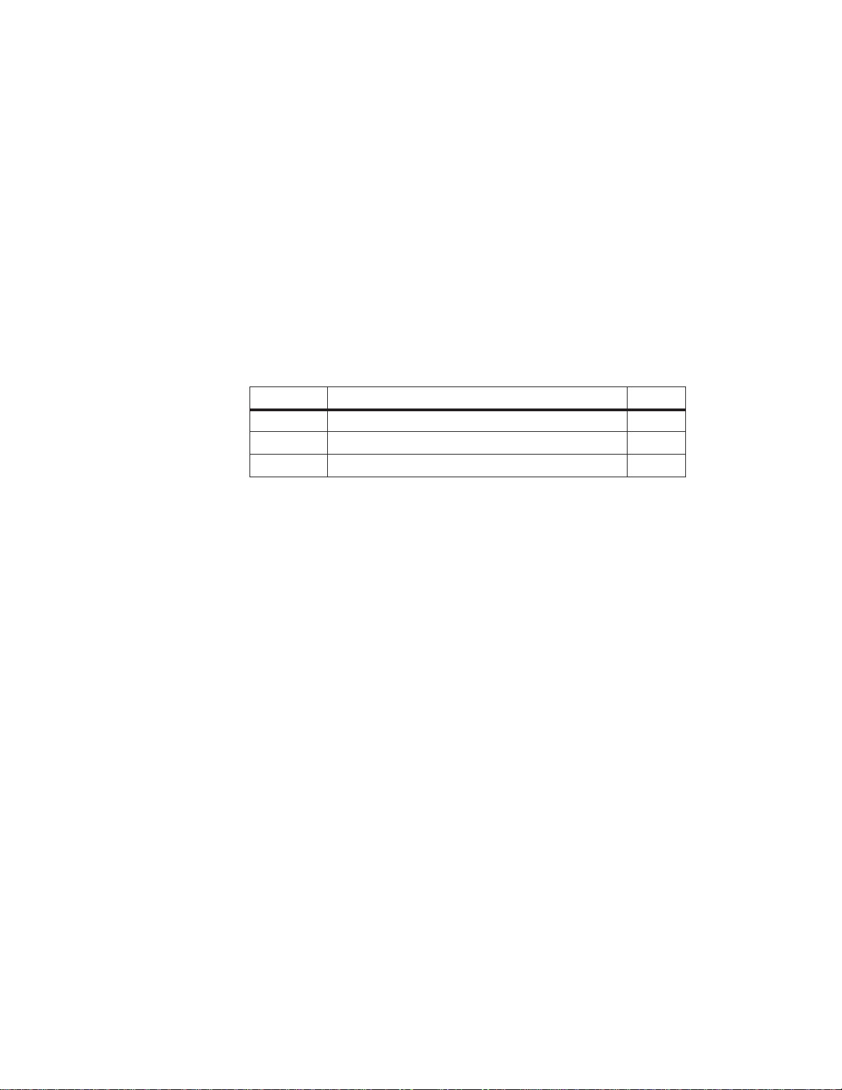
With the centralized configuration, you can install the CC and EUs in the
same cabinet or in adjacent cabinets. Data transmission is parallel. Shown in
the following figure is a centralized configuration.
EU
System Manual
C79000-G8576-C199-06
EU
CC
Load Power Supply
Figure 2-1 Centralized Configuration
2-3
Page 22

Centralized and Distributed Configuration of a Programmable Controller
With the distributed configuration, a distinction is made between parallel and
serial communication. The main features of these types of communication
are as follows:
S Parallel fast data transmission line length of up to 600 m
S Serial slower data transmission line length of up to 3000 m
2.2.1 Installing a PLC with Centralized Configuration
The following table shows which interface modules and connecting cables
can be used for connecting the various expansion units to the CC in a
centralized configuration.
Interface Module
Expansion Unit Interface Module
in the CC
IM 300-3
6ES5 300-3AB11
EU 183U
EU 185U
IM 312-3
6ES5 312-3AB11
(I/O mod. only)
IM 301-3 1)
6ES5 301-3AB13
EU 183U
EU 185U
IM 312-3
6ES5 312-3AB31
(I/O mod. only)
IM 300-5
6ES5 300-5CA11
IM 301-5
1)
6ES5 301-5CA12
IM 300-5
6ES5 300-5LB11
1)
This IM has a second interface for distributed communication.
2)
The last IM 312-3 always requires a 6ES5 760-0AB11 terminator .
EU 184U
EU 187U
EU 184U
EU 187U
IM 312-5
6ES5 312-5CA11
IM 312-5
6ES5 312-5CA21
ER 701-1 IM 306
6ES5 306-7LA11
in the EU
2)
2)
Connecting Cable
Max. Distance
fixed to the IM 312 module
0.5 m; 0.95 m
fixed to the IM 312 module
0.5 m; 0.95 m
fixed to the IM 312 module
0.5 m; 1.5 m
fixed to the IM 312 module
0.5 m; 1.5 m
6ES5 705-0xxxx
0.5 m to 2,5 m
2-4
To install a PLC in a centralized configuration, you must observe the
following conditions:
S A centralized configuration is generally only suitable for connecting I/O
modules (DI, DO, AI, AO) and some intelligent I/O modules (IPs) in the
EU (see the Configuring Aids in the catalog and Chapter 4).
S The line length between the IM in the CC and the last IM in the EU must
not exceed 2 m.
C79000-G8576-C199-06
System Manual
Page 23
pp
Centralized and Distributed Configuration of a Programmable Controller
2.2.2 Installing a PLC with Distributed Configuration
To install a PLC in a distributed configuration, you have a choice of
parallel/symmetrical and serial communication. The following table shows
which interfaces and connecting cables can be used to connect the various
expansion units (EUs/ERs) to the CC in a distributed configuration.
Interface Module
in the CC
IM 301-3
6ES5 301-3AB13
(not for S5-155H)
IM 301-5
6ES5 301-5CA12
IM 304
6ES5 304-3UB11
IM 308
6ES5 308-3UA12
IM 308-B
6ES5 308-3UB11
IM 307
6ES5 307-3UA11
Expansion Unit Interface Module in
the EU
EU 183U
ER 701-2
ER 701-3
EU 183U
EU 185U
ER 701-2
ER 701-3
EU 183U
EU 185U
ER 701-2
ER 701-3
EU 183U
EU 185U
ET 100U
(Catalog ST 52.1)
ICM 560 –
ET 200 IM 318-B
ER 701-2
ER 701-3
EU 183U
EU 185U
1)
IM 310
6ES5 310-3AB11
1)
IM 310
6ES5 310-3AB11
1)
IM 314
6ES5 314-3UA11
IM 318-3
6ES5 318-3UA11
IM 318-8
6ES5 318-8MA12
6ES5 318-8MB11
IM 317
6ES5 317-3UA11
IM 317
6ES5 317-3UA11
Connecting Cable
Max. Permiss. Line Length
6ES5 721-0xxxx
1 m to 200 m
6ES5 721-0xxxx
1 m to 600 m
6ES5 707-5AA00
V45551-F21-B5
up to 3000 m
Cable connection
6ES5 722-2xxxx
Fiber optic cable up to 1500 m
1)
The last IM 310 or IM 314 always requires a 6ES5 760-1AA11 terminator.
System Manual
C79000-G8576-C199-06
The ER 701-2 and ER 701-3 always additionally require an IM 306 for
communication via an IM 304, IM 307 or IM 308.
To install a PLC in a distributed configuration, you must observe the
following conditions:
S With the IM 301/IM 310 pair of interface modules, you can only use I/O
modules (DI, DO, AI, AO) and IPs without page addressing in the EUs.
S With the IM 304/314 pair of interface modules, you can use all IPs, CPs
and I/O modules in the EU 185U.
Note
The IM 307/317, IM 308/318 and IM 308-B/318-B each have their own
manual (see catalog).
2-5
Page 24
Centralized and Distributed Configuration of a Programmable Controller
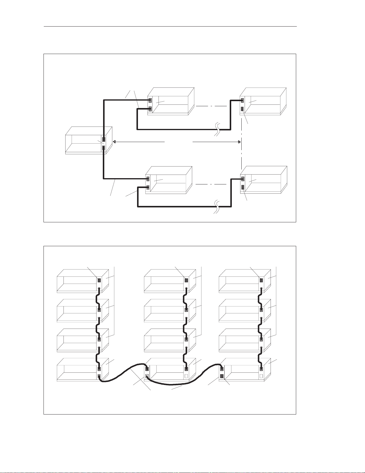
2.3 Examples
Given in the following are some examples of centralized and distributed
configuration of various SIMATIC S5 components.
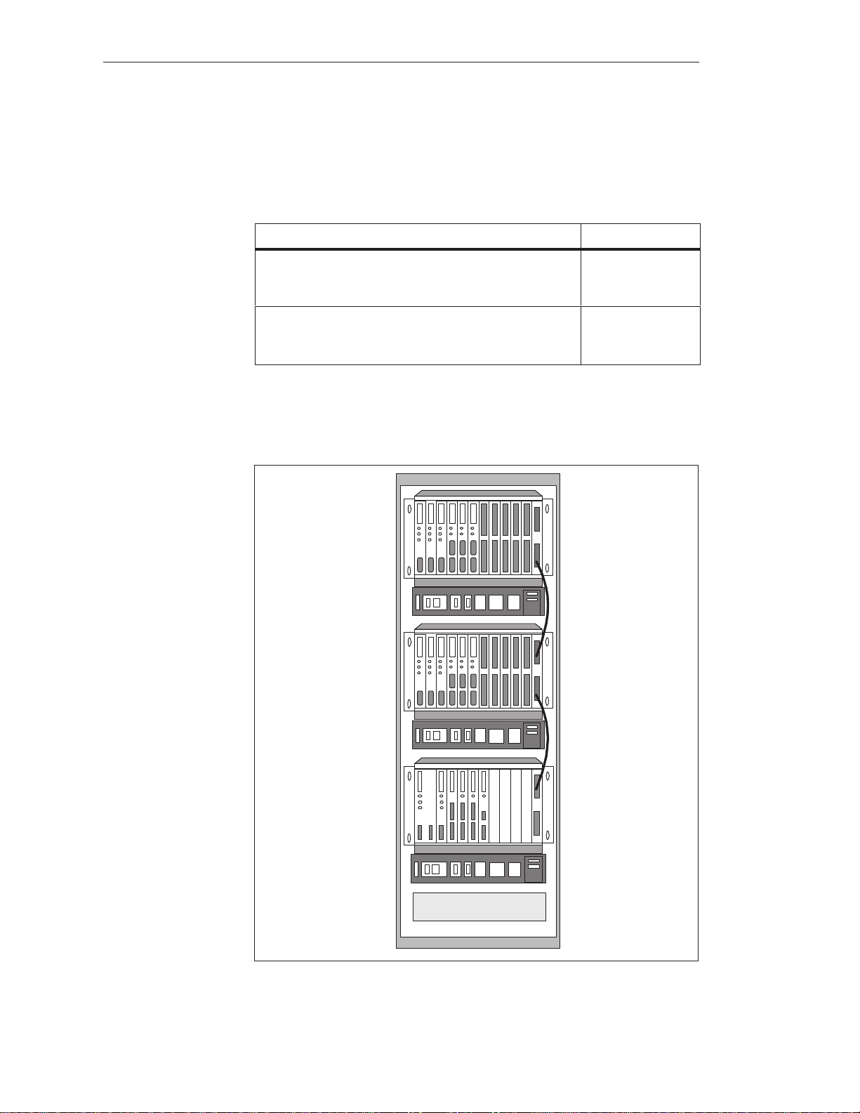
3 EUs max.
EU 184U
EU 184U
EU 184U
CC S5-135U/155U
IM 312-5
IM 312-5
IM 312-5
IM 300-5
4 EUs max.
EU183U
EU183U
CC S5-135U/155U
IM 312-3
6ES5 760-0AB11
IM 312-3
IM 300-3
Figure 2-2 Centralized Configuration of an S5-135U/155U with the IM 300
and IM 312
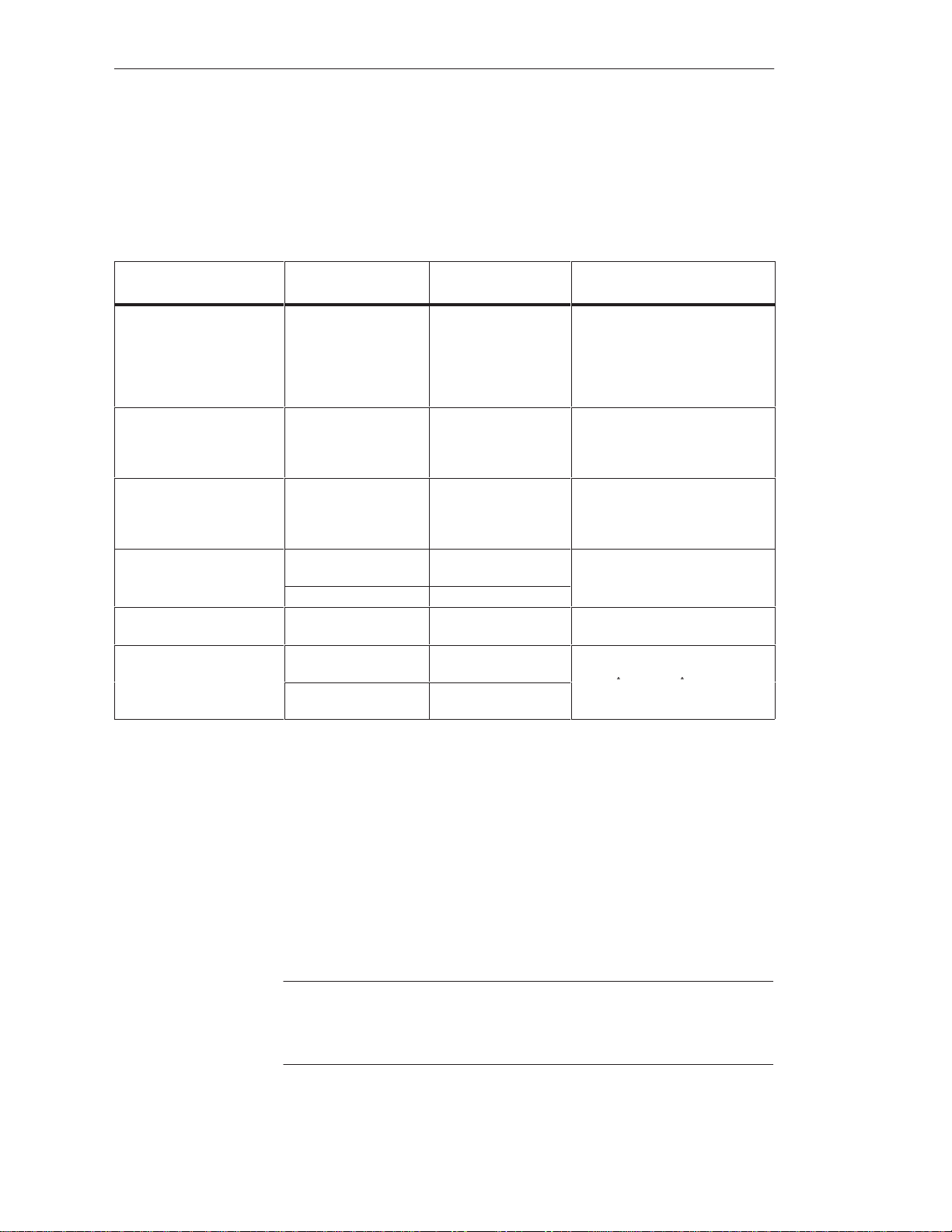
3 ERs max.
2-6
ER 701-1
ER 701-1
ER 701-1
IM 306
IM 306
IM 306
IM 300-5LB
CC S5-135U/155U
Figure 2-3 Centralized Configuration of an S5-135U/155U with ER 701s
C79000-G8576-C199-06
System Manual
Page 25
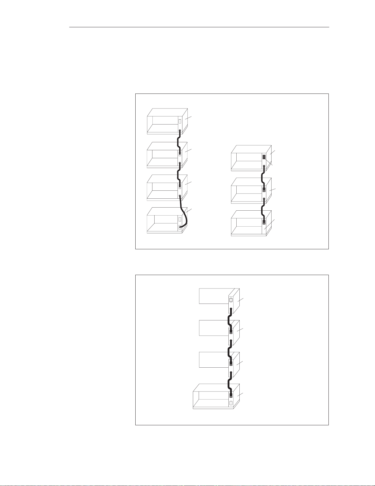
IM 304
CC S5-135U/155U
Centralized and Distributed Configuration of a Programmable Controller
6ES5 721-0xxx0
EU185U
IM 314
600m max.
4 EUs max.
EU 185U
IM 314
6ES5 760-1AA11
EU185U
IM314
6ES5 721-0xxx0
Figure 2-4 Distributed Configuration of an S5-135U/155U with the IM 304 and IM 314
6ES5 760-0AB11
EU 183U
EU 183U
EU 183U
IM 312-3 IM 312-3
6ES5 760-0AB11
EU 183U
EU 183U
EU 183U
4 EUs max.
6ES5760-0AB11
EU 183U
EU 183U
EU 183U
EU 185U
IM 314
6ES5 760-1AA11
IM312-3
IM 300-3
IM 310-3
EU 183U
6ES5 760-0AA11
CC S5-135U/155U
IM 301-3
IM 310-3
EU 183U
6ES5 721-0xxx0
Figure 2-5 Distributed Configuration of an S5-135U/155U with Expansion Units in Centralized Configuration
System Manual
C79000-G8576-C199-06
IM 300-3
2-7
Page 26

Centralized and Distributed Configuration of a Programmable Controller
2-8
C79000-G8576-C199-06
System Manual
Page 27

Installation Guidelines
The Installation Guidelines provide you with information for the
interference-free installation of the SIMATIC S5-135U/155U programmable
controllers.
This chapter describes the following:
Paths which serve for interference pickup in programmable controllers,
and five rules for ensuring electromagnetic compatibility (EMC)
Interference-free installation of the programmable controllers
Cable routing, the connecting of cable shields and equipotential bonding
between equipment
The power supplies for control and load circuits, and the different
grounding concepts
Shielding and grounding for the connection of centralized and distributed
expansions and monitors to programmable controllers
The selection and design of cabinets
3
Chapter
Overview
Section Description Page
3.1 Principles of Installation of Systems for EMC 3-2
3.2 Installation of Programmable Controllers for EMC 3-8
3.3 Wiring of Programmable Controllers for EMC 3-12
3.4 Power Supplies for Programmable Controllers and I/Os 3-20
3.5 Interference-Free Installation of Centralized and
Distributed Interface Circuits
3.6 Interference-Free Connection of Monitors 3-30
3.7 Selection and Installation of Cabinets with SIMA TIC S5 3-33
3-28
System Manual
C79000-G8576-C199-06
3-1
Page 28
Installation Guidelines
3.1 Principles of Installation of Systems for EMC
What Does EMC
Mean?
Electromagnetic compatibility (EMC) is understood to mean the capability of
electrical equipment to operate correctly in a defined electromagnetic
environment, without being affected by the environment and without
affecting the environment to an unacceptable degree.
All SIMATIC S5 products have been developed for applications in harsh
industrial environments and meet high requirements for EMC. Before
installing the control system, however, you should still carry out EMC
planning and involve possible interference sources in the assessment.
Described in the following chapter are
the various paths over which interference can be picked up in the PLC,
typical interference sources and their coupling mechanisms,
basic rules for ensuring EMC.
3.1.1 Overview of Possible Types of Interference
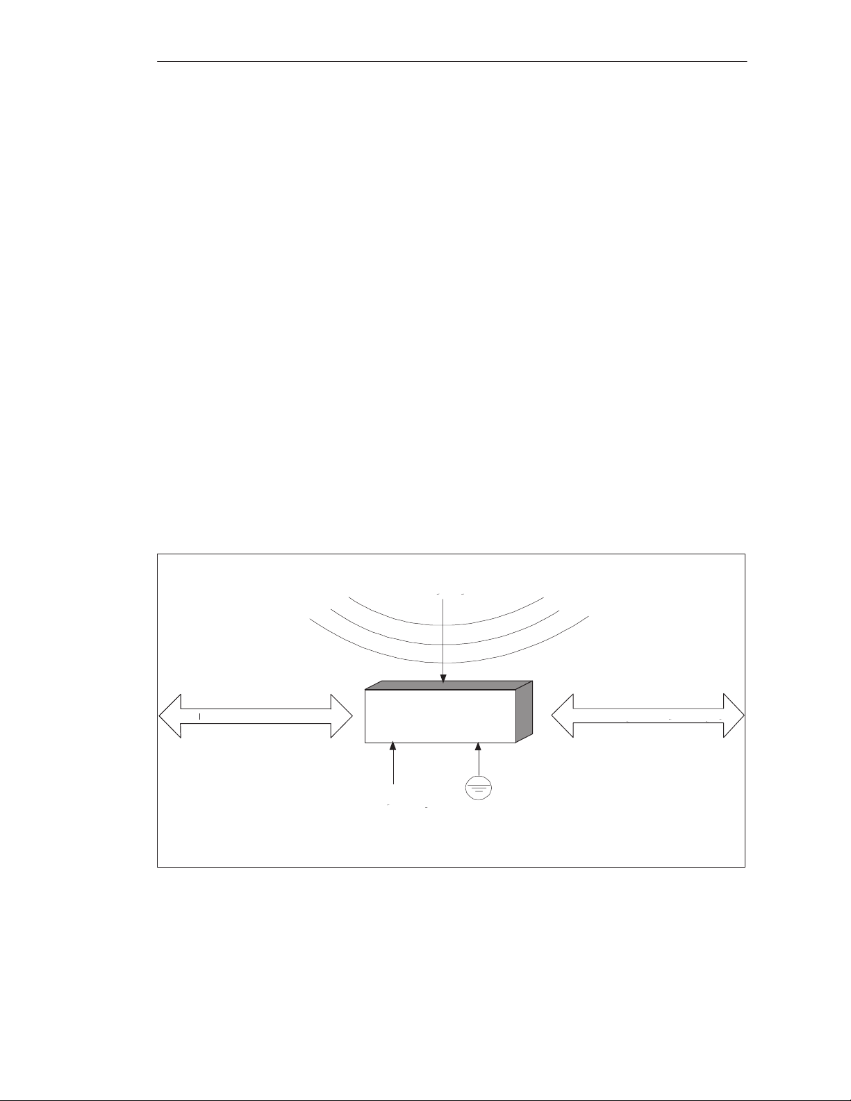
Electromagnetic interference can be picked up over different paths by the
programmable controller:
Fields
SINEC Bus System
Programmable
Controller
Power Supply
Protective Conductor
Figure 3-1 Electromagnetic Interference with Programmable Controllers
3-2
I/O Signal Lines
C79000-G8576-C199-06
System Manual
Page 29

Installation Guidelines
Depending on the propagation medium (conducted or non-conducted
interference) and distance from the source, interference can be picked up by
the programmable controller via different coupling mechanisms.
A distinction is made between the following:
Direct coupling
Capacitive coupling
Inductive coupling
Radiated interference
System Manual
C79000-G8576-C199-06
3-3
Page 30
s
g
Installation Guidelines
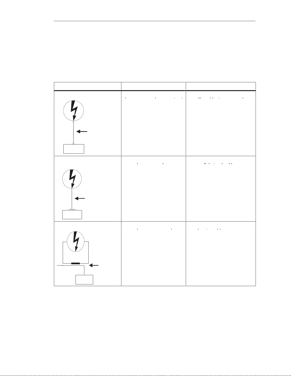
Coupling
Mechanisms and
Shown in the following table are the four different coupling mechanisms,
their causes, and possible interference sources.
Typical
Interference
Sources at a
Glance
Coupling Mechanism Cause Typical Interference Sources
Direct Coupling Direct or metallic coupling
always occurs when two circuit
Interference
have a common conductor
Switched devices (supply
affected by inverters and
external power supply units)
Motors being started
Different potentials of
component cases with a
common power supplys
Static discharges
SIMATIC S5
Direct Coupling
Path
Capacitive Coupling Capacitive or electrical coupling Interference pickup via
Interference
Capacitive Coupling
Path
occurs between conductors
which are at different potentials.
The degree of coupling is
proportional to the voltage
variation as a function of time.
parallel signal cables
Static discharge of the
operator
Contactors
SIMATIC S5
Inductive Coupling Inductive or magnetic coupling
occurs between two conductor
Signal
3-4
Interference
Inductive
Coupling Path
SIMATIC S5
loops through which current is
flowing. Interference voltages
are induced by the magnetic
fluxes associated with the
currents. The degree of couplin
is proportional to the current
variation as a function of time.
Transformers, motors,
electric welders
Parallel AC supply cables
Cables whose currents are
switched⁄
Signal cables with a high
frequency
Unconnected coils
C79000-G8576-C199-06
System Manual
Page 31

Coupling Mechanism Typical Interference SourcesCause
n
Installation Guidelines
Radiated Interference There is a radiation path when a
conductor is subjected to an
electromagnetic wave.
Interference
Radiation Path
SIMATIC S5
Impinging of the wave results i
induced currents and voltages.
Local transmitters
(e.g. two-way radios)
Spark gaps (spark plugs,
collectors in electric motors,
welders)
System Manual
C79000-G8576-C199-06
3-5
Page 32

Installation Guidelines
3.1.2 The Most Important Basic Rules for Ensuring EMC
It is often sufficient to comply with a few elementary rules for ensuring
EMC. When installing the control system, therefore, observe the following
five basic rules.
When installing the programmable controllers, provide large-area good
quality grounding of the inactive metal parts (see Section 3.2).
Make a large-area low-impedance interconnection of all inactive metal
parts.
For screw connections on painted and anodized metal parts, either use
special contact washers or remove the insulating protective layers.
If possible, do not use aluminum parts. Aluminum oxidizes easily and is
therefore less suitable for grounding.
Make a central connection between the chassis ground and the
ground/protective ground conductor system.
Ensure proper routing of lines when wiring (see Sections 3.3.1 and 3.3.2).
Arrange the cabling in line groups. (AC power cable, power supply lines,
signal lines, data lines)
Always install AC power cables and signal or data lines in separate ducts
or bunches.
Route the signal and data lines as closely as possible to grounded surfaces
such as cabinet elements, metal bars and cabinet panels.
Ensure that cable shields are properly secured (see Section 3.3.3).
Data lines must be shielded. The shield should be connected at both ends.
Analog lines must be shielded. For the transfer of signals with low
amplitudes, it may be advisable to connect the shield at only one end.
Provide the line shields with a large-area connection to a shield/protective
conductor bar immediately after the cabinet inlet, and secure the shields
with cable clamps. Route the grounded shield as far as the module
without interruption, but do not connect the shield there again.
Ensure that the shield/protective ground bar has a low-impedance
connection to the cabinet.
Use metal or metallized connector cases for shielded data lines.
3-6
C79000-G8576-C199-06
System Manual
Page 33

Installation Guidelines
Employ special EMC measures for particular applications (see
Section 3.3.4).
Fit quenching elements to all inductances which are not controlled by
SIMATIC S5 modules.
Use incandescent bulbs for illuminating cabinets, and avoid fluorescent
lamps.
Create a standard reference potential; ground all electrical apparatus if
possible (see Sections 3.4 and 3.5).
Use specific grounding measures. Grounding of the control system is a
protective and functional measure.
System parts and cabinets with central controllers and expansion units
should be connected to the ground/protective conductor system in star
configuration. This serves to avoid the creation of ground loops.
In the case of potential differences between system parts and cabinets,
install equipotential bonding conductors of sufficient rating.
System Manual
C79000-G8576-C199-06
3-7
Page 34

Installation Guidelines
3.2 Installation of Programmable Controllers for EMC
Measures for suppressing interference voltages are often applied only when
the control system is already operational and proper reception of a useful
signal is impaired. The reason for such interference is usually inadequate
reference potentials caused by mistakes in equipment assembly. Described in
the following sections are:
Basic rules for grounding the inactive metal parts
Examples of cabinet assembly for EMC
Example of rack and wall mounting for EMC
3.2.1 Basic Rules for Assembling and Grounding the Inactive Metal Parts
Ensure wide-area chassis grounding of the inactive metal parts when
mounting the equipment. Properly implemented grounding creates a uniform
reference potential for the control system, and reduces the effects of
picked-up interference.
Chassis grounding is understood to mean the electrical connection of all
inactive parts. The entirety of all interconnected inactive parts is the chassis
ground.
Inactive parts are conductive parts which are electrically isolated from active
parts by basic insulation, and can only develop a voltage in the event of a
fault.
The chassis ground must not develop a dangerous touch voltage, even in
the event of a fault. The ground must therefore be connected to the protective
ground conductor. To prevent ground loops, locally separated ground
elements such as cabinets, structural and machine parts, must always be
connected to the protective ground system in star configuration.
Ensure the following when chassis grounding:
Connect the inactive metal parts with the same degree of care as the
active parts.
Ensure low-impedance metal-to-metal connections, e.g. with large-area
good quality contact.
When you are incorporating painted or anodized metal parts in the
grounding, these insulating protective layers must be penetrated. Use
special contact washers or remove the insulating layer.
Protect the connection points from corrosion, e.g. with grease.
Movable grounded parts such as cabinet doors must be connected via
flexible grounding strips. The grounding strips should be short and have a
large surface because the surface is decisive in providing a path to ground
for high-frequency interference.
3-8
C79000-G8576-C199-06
System Manual
Page 35

3.2.2 Example of Cabinet Assembly for EMC
The example of cabinet assembly in the figure shows the various measures,
the grounding of inactive metal parts and the connection of shielded cables.
This example applies only to grounded operation. Follow the points
numbered in the figure during assembly.
Installation Guidelines
1
2
3
Figure 3-2 Example of Cabinet Assembly for EMC
System Manual
C79000-G8576-C199-06
4
5
6
7
8
3-9
Page 36

Installation Guidelines
À Grounding strips
If there are no large-area metal-to-metal connections, you must
connect inactive metal parts such as cabinet doors and supports
with grounding strips. These should be short and have a large surface.
Á Cabinet members
The cabinet members should have a large-area connection to the
cabinet housing (metal-to-metal connection).
 Mounting bracket for subrack
There must be a large-area metal-to-metal connection between
cabinet member and mounting bracket.
à Signal lines
With shielded signal lines, the shield must be secured to the
protective conductor bar or an additionally fitted shield bar using
large-area cable clamps.
Ä Cable clamp
The cable clamp must enclose and make contact with the shield braid
over a large area.
Å Shield bar
This bar must have a large-area connection to the cabinet members
(metal-to-metal connection). It serves for grounding the cable shields.
Æ Protective conductor bar
The protective conductor bar must have a large-area connection to
the cabinet members (metal-to-metal connection). The protective
conductor bar must be connected to the protective conductor system
via an external conductor (at least 10 mm2 ). This is essential for
providing a reliable path to ground for fault currents and interference
currents.
Ç Conductor to the protective conductor system (ground point)
The conductor must have a large-area connection to the protective
conductor system (ground point).
3-10
C79000-G8576-C199-06
System Manual
Page 37

3.2.3 Example of Rack and Wall Mounting for EMC
To operate your control system in a low-interference environment whilst
observing the permissible ambient conditions (see “Technical
Specifications”), you can mount the programmable controllers on racks or
directly on walls.
Picked-up interference should be given a path to large metal surfaces. You
should therefore secure standard sectional rails, shield and protective
conductor bars to metal structural elements. For wall mounting in particular,
installation on reference potential surfaces made of sheet steel has proved
advantageous.
When installing shielded cables, provide a shield bar for connecting the cable
shields. The shield bar can also be the protective conductor bar.
Ensure the following for rack and wall mounting:
S Suitable contacting aids should be used on painted and anodized metal
parts. Use special contact washers or remove the insulating protective
layers.
S Provide large-area, low-impedance metal-to-metal connections when
securing the shield/protective conductor bar.
S AC conductors must be covered.
Installation Guidelines
Connection to
P . Ground: 10 mm@
Figure 3-3 W all Mounting of an S5-135/155U PLC
System Manual
C79000-G8576-C199-06
Reference Potential
Surface
Shielded Signal
Line
Cable Clamp for
Shield Contact
Shield/Protective
Conductor Bar
3-11
Page 38

Installation Guidelines
3.3 Wiring of Programmable Controllers for EMC
The following section describes:
Routing of cables within and outside cabinets
Equipotential bonding between devices
Single and double-ended connection of cable shields
Checklist for electromagnetically compatible installation
3.3.1 Routing of Cables
This section covers the routing of bus, signal and supply lines. The purpose
cable routing is to suppress crosstalk between cables laid in parallel.
Routing of Cables
Within and
Outside Cabinets
Group A
Group B
Group C
Group D
For electromagnetically compatible routing of cables and lines, it is
expedient to subdivide the lines into the following line groups and lay the
groups separately.
Shielded bus and data lines (for programmer, OP, SINEC L1, SINEC L2,
printer, etc.)
Shielded analog lines
Unshielded lines for DC voltage v 60 V
Unshielded lines for AC voltage v 25 V
Coaxial cables for monitors
Unshielded lines for DC voltage > 60V and v 400V
Unshielded lines for AC voltage > 25V and v 400V
Unshielded lines for DC and AC voltage > 400V
Lines for SINEC H1
From the combination of individual groups in the following table, you can
read off the conditions for laying the line groups.
3-12
Group A
Group B
Group C
Group D
Group A Group B Group C Group D
C79000-G8576-C199-06
System Manual
Page 39

Legend for the table
Lines can be laid in common bundles or cable ducts.
Lines must be laid in separate bundles or cable ducts (without
minimum clearance).
Lines within cabinets must be laid in separate bundles or cable
ducts; outside the cabinets but within buildings, they must be laid
over separate cable routes with a clearance of at least 10 cm.
Lines must be laid in separate bundles or cable ducts with a
clearance of at least 50 cm.
Installation Guidelines
Routing of Cables
Outside Buildings
Lightning
Protection
!
Outside buildings, lay the lines on metal cable trays if possible. Provide the
joints between cable trays with an electrical connection and ground the cable
trays.
When laying lines outside buildings, you must observe the valid lightning
protection and grounding measures. The following applies in general:
Caution
Where cables and lines for SIMATIC S5 controllers are to be laid
outside buildings, you must apply measures for internal and external
lightning protection.
Outside the buildings, lay your lines either
in metal conduit grounded at both ends,
or
in concreted cable ducts with continuously connected reinforcement.
Protect the signal lines from overvoltages by means of
varistors
or
inert gas-filled surge diverters.
Equipotential
Bonding
System Manual
C79000-G8576-C199-06
Fit these protective devices at the cable entry into the building.
Note
Lightning protection measures always require an individual assessment of
the entire installation. For clarification, please consult your Siemens regional
office or a company specializing in lightning protection.
Ensure adequate equipotential bonding between the connected equipment
(see Section 3.3.2).
3-13
Page 40

Installation Guidelines
3.3.2 Equipotential Bonding
Between separate sections of an installation, potential differences can
develop if
S programmable controllers and I/O devices are connected via a
non-floating link, or
S cable shields are connected at both ends and are grounded at different
parts of the system.
Different AC supplies, for example, can cause potential differences. These
differences must be reduced by installing equipotential bonding conductors to
ensure functioning of the electronic components.
The following points must be observed for equipotential bonding:
S The lower the impedance of the equipotential bonding conductor, the
greater is the effectiveness of equipotential bonding.
S Where shielded signal lines are laid between the relevant sections of the
system and connected at both ends to the ground/protective conductor, the
impedance of the additional equipotential bonding conductor must not
exceed 10 % of the shield impedance.
S The cross-section of the equipotential bonding conductor must be rated
for the maximum circulating current. The following cross-sections of
copper have proved to be satisfactory in practice:
–16 mm@ of copper for equipotential bonding conductors
of up to 200 m in length
–25 mm@ of copper for equipotential bonding conductors
of more than 200 m in length.
S Use copper or zinc-plated steel for equipotential bonding conductors.
They must be given a large-area connection to the ground/protective
conductor and protect it from corrosion.
S The equipotential bonding conductor should be laid so that the smallest
possible areas are enclosed between the equipotential bonding conductor
and signal lines.
3-14
Signal Line
Equipotential Bonding Conductor
Figure 3-4 Routing of Equipotential Bonding Conductor and Signal Line
C79000-G8576-C199-06
System Manual
Page 41

3.3.3 Shielding of Cables and Lines
Shielding is a method of attenuating magnetic, electrical or electro-magnetic
interference fields. Interference currents on cable shields are given a path to
ground via the shield bar which is electrically connected to the housing. A
low-impedance connection to the protective conductor is particularly
important so that these interference currents themselves do not become an
interference source.
Where possible, only use lines with a braided shield. The coverage density of
the shield should be more than 80 %. Avoid lines with a foil shield because
the foil can be very easily damaged by tensile strain and compression during
fitting; this results in reduced effectiveness of the shield.
As a rule, line shields should always be connected at both ends. This is the
only way to achieve a good degree of interference suppression in the higher
frequency region.
Only in exceptional cases should the shield be connected at one end only, as
this only achieves attenuation of the low frequencies. Single-ended shield
connection may be more advantageous when:
Installation Guidelines
an equipotential bonding conductor cannot be laid;
analog signals (of a few mV or mA) are to be transmitted;
foil (static) shields are used.
With data lines for serial communication, always use metal or metallized
connectors. Secure the shield of the data line to the connector case. Do not
connect the shield to Pin 1 of the connector.
For stationary operation, it is advisable to fully strip the insulation from the
shielded cable and connect it to the shield/protective conductor bar.
Note
In the event of potential differences between ground points, a circulating
current may flow through the shield connected at both ends. In this case,
install an additional equipotential bonding conductor (see Section 3.3.2).
System Manual
C79000-G8576-C199-06
3-15
Page 42

Installation Guidelines
Please observe the following points when connecting the shield:
Use metal cable clamps for securing the braided shield. The clamps must
enclose the shield over a large area and provide a good contact.
Connect the shield to a shield bar immediately after the cable entry into
the cabinet. Route the shield as far as the module but do not connect it
there again.
Figure 3-5 Example of Securing Shielded Lines with Cable Clamps
3-16
C79000-G8576-C199-06
System Manual
Page 43

Installation Guidelines
3.3.4 Special Measures for Interference-Free Operation
Fitting Quenching
Elements to
Inductances
As a rule, inductances such as contactor or relay coils controlled by
SIMATIC S5 do not require external quenching elements in the circuit,
because the quenching elements are already integrated in the modules.
Inductances should only be fitted with quenching elements
when SIMATIC S5 output currents can be switched off by additionally
fitted contacts, such as relay contacts. In this case the integrated
quenching elements in the modules are no longer effective;
if they are not controlled by SIMATIC S5 modules.
You can place freewheel diodes, varistors or RC networks in circuit with
inductances.
Circuitry for DC-Operated
Inductances
With Diode With Zener Diode With Varistor With RC Network
Circuitry for AC-Operated
Inductances
Figure 3-6 Quenching Circuits for Inductances
System Manual
C79000-G8576-C199-06
3-17
Page 44

Installation Guidelines
AC Power
Connection for
Programmers
Cabinet Lighting
A power socket should be fitted in each cabinet for the AC supply to
programmers. The sockets should be powered from the distribution system to
which the protective conductor for the cabinet is also connected.
Use incandescent bulbs, such as LINESTRA lamps, for cabinet lighting.
Avoid using fluorescent lamps because they generate interference fields. If
the use of fluorescent lamps cannot be avoided, apply the measures shown in
the following figure.
Screen Over the Lamp
Shielded Cable
Metal-Enclosed Switch
AC Filter or
Shielded Power Cable
Figure 3-7 Measures for Interference Suppression of Fluorescent Lamps in a
Cabinet
3-18
C79000-G8576-C199-06
System Manual
Page 45

Installation Guidelines
3.3.5 Checklist for the Electromagnetically Compatible Installation of
Control Systems
EMC Measures Notes
Connection of inactive parts (Section 3.2)
Check, in particular, the connections on:
Subracks
Cabinet members
Shield and protective conductor bars
Do all inactive metal parts have a large-area, low-impedance
interconnection and ground?
Is there a satisfactory connection to the ground/protective conductor
system?
Have insulating layers on painted and anodized surfaces been
removed, or have special contact washers been used for the
connections?
Are connections protected from corrosion, e.g. by grease?
Are cabinet doors connected to the cabinet element with grounding
strips?
Routing of cables (Section 3.3.1)
Cabling subdivided into line groups?
Supply cables (230 to 400 V) and signal lines laid in separate ducts or
bundles?
Equipotential bonding (Section 3.3.2)
With a separate arrangement, check that the equipotential bonding
conductor has been correctly laid.
Shielding of cables (Section 3.3.3)
Have metal connectors been used throughout?
Are all analog and data lines shielded?
Are line shields connected to the shield or protective conductor bar at
the cabinet entry?
Are line shields secured with cable clamps over a large area and at
low impedance?
Are line shields connected at both ends where possible?
Inductances (Section 3.3.4)
Are contactor coils which are switched via contacts, fitted with
quenching elements?
System Manual
C79000-G8576-C199-06
3-19
Page 46

Installation Guidelines
3.4 Power Supplies for Programmable Controllers and I/Os
This section describes:
Which circuits you must distinguish in the control system and which
demands are made on the power supply.
Connection and grounding concept with higher-level infeed from
grounded, centrally grounded and ungrounded supplies.
Connecting the power supply to non-isolated and isolated modules.
3.4.1 Power Supplies for Control Systems with SIMATIC S5
For control systems with SIMATIC S5, you will need:
A power supply for the internal PLC circuits (control power supply)
and a load power supply for the input and output circuits.
Power Supply for
the PLC Circuits
Load Power
Supply for the I/Os
!
The power supply for the internal PLC circuits powers the CPU and the
modules used.
Note
Ensure that the control power supply is not overloaded. Make a current
addition and estimate the current drawn by all modules.
The load power supply feeds the input and output circuits (load circuits) as
well as sensors and actuators. Only a power supply which offers safe
electrical isolation from the AC system may be used for the 24 V DC supply.
Caution
Only safety-separated low voltage DC v 60 V may be used for the 24 V DC
supply. The safety separation can be implemented according to the
requirements of, amongst other sources, VDE 0100, Part 410/HD
384-4-41/IEC 364-4-41 (functional extra-low voltage with safety separation)
or VDE 0805/EN 60950/IEC 950 (safety extra-low voltage SELV) or VDE
0106, Part 101.
3-20
C79000-G8576-C199-06
System Manual
Page 47

Installation Guidelines
Ratings of Load
Power Supplies
Load Power
Supply for
Non-Floating
Modules
Load Power
Supply for
Floating Modules
The electronic short-circuit protection of digital output modules only
responds when 3-times the rated current is exceeded. You should therefore so
design the load power supply units that the unit can supply the current
required for shutting down in the event of a short-circuit at one output.
In the event of short-circuits at digital outputs, if the load power supply is not
adequately rated, a current which is higher than the rated current can flow for
a longer period without responding of the electronic short-circuit protection
of the DQ module. Operation in the overload region can destroy the module.
If you use non-floating modules, you must create a common reference
potential for the internal control circuits of the PLC and for the load circuits.
The reference potential of the load power supply should therefore be
connected to the ground terminal of the PLC (PE or protective conductor
terminal). The ground terminal is permanently connected to the internal
reference potential of the controller.
Note
If you use switched-mode power supply units for floating analog modules
and BEROs, you must fit an AC system filter to the input of the power
supply.
3.4.2 Connecting the Programmable Controller and Load Power
Each of the following figures shows a circuit example for connecting the
control and load power supplies as well as the grounding concept for
operation from:
Grounded supplies
Centrally grounded supplies
Ungrounded supplies
When assembling the control system, observe the following explanations.
The text contains identification numbers relating to Figures 3-8 to 3-10.
Main Switch and
Protection
For the programmable controller, sensors and actuators, you must fit a
main switch to DIN VDE 0113, Part 1, or an isolating device to DIN
VDE 0100, Part 460. If an AC plug is used as the isolating device, the
socket must be in the vicinity of the central controller and must be easily
accessible (VDE 0805, 1.7.2). These devices are not required in the case
of a subsystem where the appropriate devices are fitted at a higher level.
The circuits for sensors and actuators can be given group protection for
short-circuit and/or overload . According to VDE 0100, Part 725,
single-phase protection is required; and all-phase protection to DIN VDE
0113, Part 1.
System Manual
C79000-G8576-C199-06
3-21
Page 48

Installation Guidelines
Load Power
Supply
Grounding
For 24 V DC load circuits, you require a load power supply unit with
safety separation. If an AC plug is used as the isolating device, the socket
must be in the vicinity of the central controller and easily accessible
(VDE 0805, 1.7.2).
Unregulated load power supply units require a reservoir capacitor
(rated at 200 mF per 1 A load current). Connect the capacitor in parallel
with the output terminals of the load power supply.
According to DIN VDE 0113, Part 1, control systems with more than five
items of electromagnetic apparatus require isolation by a transformer;
according to DIN VDE 0100, Part 725, it is recommended .
Load power supplies should be grounded if possible . Provide a
detachable connection to the protective conductor at the load power
supply unit (terminal L- or M) or on the secondary side of the isolating
transformer.
Caution
!
For ungrounded power supplies, you must provide insulation monitoring if⁄
hazardous system states can be caused by double faults;
there is no safety separation;
circuits are operated with voltages of more than 120 V DC;
circuits are operated with voltages of more than 50 V AC.
3-22
C79000-G8576-C199-06
System Manual
Page 49

Installation Guidelines
Operating a
Programmable
Controller with
Process I/Os from
a Grounded
Supply
Low-Voltage Distribution
e.g. TN-S System
L1
L2
L3
N
PE
Control Power Supply
AC
Operation from grounded power supplies offers the best rejection of
interference.
DC
L+
L–
L1
N
Cabinet
L+/L1
L–/N
PE
PS
U
0 V
int
CPU
Non-Floating Input
Programmable Controller
Non-Floating Output
Floating
Input
Floating
Output
PE
Protective Conductor Bar
in Cabinet
AC
AC
24 to 230 V AC Load Supply
Process I/Os
for AC Modules
AC
DC
5 to 60 V DC Load Supply for
Non-Floating DC Modules
AC
DC
5 to 60 V DC Load Supply
for Floating DC Modules
Figure 3-8 Operating a Programmable Controller with Process I/Os from a Grounded Supply
System Manual
C79000-G8576-C199-06
3-23
Page 50

Installation Guidelines
Operating a
Programmable
Controller with
Process I/Os from
a Centrally
Grounded Supply
Higher-Level Supply
L1
L2
L3
Control Power Supply
AC
In systems with their own transformers or generators, the PLC is connected
to the central ground. A detachable connection should be provided so that
ground faults can be measured.
The PLC should be insulated from cabinet/protective conductor potential. To
maintain this isolated arrangement, all connected devices must be operated
with capacitive grounding or ungrounded. For this reason, programmers
should only be powered via an isolating transformer.
Detachable Connection for
Measurement
Purposes
Central Ground,
e.g. Foundation
Ground
DC
Cabinet
L+/L1
L+
L-
L–/N
L1
N
PE
PS
Programmable Controller , Insulated Arrangement
U
int
CPU
0 V
Non-Floating Input
Non-Floating Output
Floating
Input
Floating
Output
PE
Protective Conductor Bar in Cabinet,
Insulated Arrangement
AC
AC
AC
DC
AC
DC
L1
N
L2 L3
Process I/Os
24 to 230 V AC Load Supply for AC Modules
5 to 60 V DC Load Supply for Non-Floating DC Modules
5 to 60 V DC Load Supply for Floating DC Modules
Figure 3-9 Operating a Programmable Controller with Process I/Os from a Centrally Grounded Supply
3-24
C79000-G8576-C199-06
System Manual
Page 51

Installation Guidelines
Operating a
Programmable
Controller with
Process I/Os from
an Ungrounded
Supply
Low-Voltage Distribution,
L1
L2
L3
e.g. IT System (3 X 230V)
PE
Control Power Supply
AC
DC
In cases in which the higher-level power supply is not grounded, you must
connect the programmable controller to a separate protective
conductor/ground (e.g. foundation ground). Operation of the PLC with
non-floating power supplies is not allowed.
When connecting the power supplies, please note:
In 3 x 230 V systems, you may connect the power supply directly to two
phases.
Programmable Controller
Non-Floating Output
Floating
Input
Floating
Output
L+
L–
L1
L2
Schrank
L+/L1
L–/L2
PE
PS
U
0 V
CPU
int
Non-Floating Input
PE
Protective Conductor Bar
Protective
in Cabinet
Conductor
Grounding
AC
AC
Process I/Os
24 to 230 V AC Load Supply
for AC Modules
AC
DC
5 to 60 V DC Load Supply
for Non-Floating DC Modules
AC
DC
5 to 60 V DC Load Supply
for Floating DC Modules
Figure 3-10 Operating a Programmable Controller with Process I/Os from an Ungrounded Supply
In 3 x 400 V systems, a connection between phase and neutral conductor is
not allowed (excessively high voltage in the event of a ground fault).
Intermediate transformers should be used in these systems.
System Manual
C79000-G8576-C199-06
3-25
Page 52

Installation Guidelines
3.4.3 Connecting Non-Floating or Floating Modules
Shown in the following sections are the specical features when installing
non-floating and floating modules.
Installation with
Non-Floating
Modules
PS
1L+
1L–
PE
Control Power
Supply
In an installation with non-floating modules, the reference potentials of the
control circuit (0 V
The reference potential of the control circuit (0 V
) and load circuits (0 V
int
) are electrically connected.
ext
) is given by the PE or
int
protective conductor terminal and must be connected to the reference
potential of the load circuit via an externally laid conductor.
Shown in the following figure is a simplified installation with non-floating
modules. The arrangement is independent of the grounding concept. The
connections for grounding are therefore not drawn.
U
CPU
External Connection for a
Standard Reference Potential
DI
DQ
int
Data
0 V
2L+
2L–
DC 24 V Load Power Supply
Figure 3-11 Simplified Representation of an Installation with Non-Floating Modules
The voltage drop on line must not exceed 1 V. Otherwise there will be a
shift in reference potentials resulting in module malfunctions.
3-26
C79000-G8576-C199-06
System Manual
Page 53

Installation Guidelines
Note
For 24 V DC digital output modules with electronic short-circuit protection,
you must ensure that the reference potential of the load power supply is
connected to terminal L- of the module. If this connection is missing (e.g.
open-circuit), a typical current of 15 mA can flow at the outputs. This output
circuit is sufficient
to prevent energized contactors or relays from being released
and to energize high-resistance loads (e.g. miniature relays).
Installation with
Floating Modules
PS
With floating modules the control circuit and load circuit are metallically
isolated.
An arrangement with floating modules is required
for all AC load circuits and
for DC load circuits which cannot be coupled. The reasons are, for
example, different reference potentials of the sensors or grounding of the
positive terminal of a battery.
Shown in the following figure is a simplified installation with floating
modules. The arrangement is independent of the grounding concept. The
connections for grounding are therefore not drawn.
CPU
DI DQ
U
int
Data
0 V
1L+
1L–
PE
24 V DC Control Power Supply
2L+
2L–
24 V DC Load Power Supply
Figure 3-12 Simplified Representation of an Arrangement with Floating Modules
System Manual
C79000-G8576-C199-06
L1
N
230 V AC Load Power Supply
3-27
Page 54

Installation Guidelines
3.5 Interference-Free Installation of Centralized and Distributed
Interface Circuits
Subjects described in the following sections are the shielding and grounding
concept with centralized and distributed interface circuits.
Information on component selection, the mechanical arrangement and wiring
can be found in the appropriate reference manuals for the interface modules.
Note
If you use components which are not approved for the installation of a
centralized or distributed interface circuit, interference rejection may be
impaired.
3.5.1 Interference-Free Installation of Centralized Interface Circuits
When you connect the central controller and expansion unit centrally via
suitable interface modules, no particular shielding and grounding measures
are required. Ensure, however, that
all subracks are interconnected at a low resistance;
the subracks in a grounded arrangement have star-configuration
grounding;
the contact springs of the modules are clean and not bent, which could
affect the path to ground for interference currents.
3.5.2 Interference-Free Installation of Distributed Interface Circuits
If you interconnect the central controller and expansion unit in a distributed
arrangement using suitable interface modules, no particular shielding and
grounding measures are usually required. Only in industrial environments
with an extremely high level of interference is there a need for special
shielding and grounding.
In these cases, please observe the following points:
Cable shields should be connected to the shield bar in the cabinet,
immediately after the cable inlet;
- insulation is fully stripped from the cable for the purpose;
- braided shields are secured to the shield bar with as large an area as
possible (e.g. with metal ties which enclose the shield over a large
area).
3-28
Shield bars should be connected to the frame or cabinet panel over a large
area.
Cable shields should be connected to the cabinet conductor.
C79000-G8576-C199-06
System Manual
Page 55

Installation Guidelines
With distributed interfacing (IM 304/IM 314 and IM 301/IM 310), ensure
that the VDE specifications for laying the protective ground are complied
with; distributed interfacing is non-floating.
The measures described above are shown in the following figure. If the
permissible potential difference between ground points can be exceeded, you
must install an equipotential bonding conductor (cross-section w 16 mm2 of
copper).
CC
IM 304
< 7 V
Figure 3-13 Shielding and Grounding the Connecting Cable
EU
IM 314
Shield/Protective
Conductor Bar
Special Features
System Manual
C79000-G8576-C199-06
With distributed interfacing, you must use the prefabricated connecting
cables. You may have excess lengths of up to 100 m when installing the
connecting cable. These excess lengths must be bifilar-wound and deposited
at a point which is protected from electromagnetic interference.
3-29
Page 56

Installation Guidelines
3.6 Interference-Free Connection of Monitors
These sections cover the following topics:
Floating connection of cables at video inputs
Shielding and grounding concept
Information on selecting the components can be found in Catalog ST80.
3.6.1 Interference-Free Connection of a Monitor to the CP of the S5
Controller
Operator control and process monitoring systems from the COROS product
family can be used with monitor connections. The physical arrangement of
apparatus and the interference level of the environment are important for the
interference-free connection of monitors to SIMATIC S5 control systems.
The choice of monitor and video cables is governed by the following:
Operation of the
Monitor and PLC
under
Low-Interference
Conditions
Operation of the
Monitor and PLC
under Industrial
Conditions
Whether the monitor and PLC are to be operated under low-interference
conditions or
under industrial conditions.
Where the monitor and PLC are installed under low-interference
environmental conditions and operated over short distances, the monitor and
PLC are at almost the same ground potentials. Interference and ground loop
disturbances are therefore not expected.
In these cases, you can drive the monitor both via TTL signals and via analog
signals. Digital cables or single-shielded coaxial cables can be used to
transmit the video signals. Note that the braided shield of the coaxial cable
serves as the return conductor and must not be connected to the shield bar.
The monitor and communication processor (CP) are interconnected without
additional shielding and grounding.
Where the monitor and PLC are installed under harsh industrial conditions
and operated over great distances, the devices may be at different ground
potentials. These different ground potentials may cause interference and
ground loop disturbances.
3-30
C79000-G8576-C199-06
System Manual
Page 57

In these cases, double-shielded coaxial cables (triaxial cables) must be used
to transmit the video signals. The inner braided shield of the coaxial cable
serves as the return conductor and must not be connected to the shield bar.
The outer braided shield provides a path to ground for interference currents
and must be incorporated in the shielding and grounding measures.
To avoid ground loops, the electronics ground and housing ground of the
monitor must be independent. This requirement is met when:
The electronics and housing grounds of the monitor are metallically
isolated,
or the electronics and housing grounds are connected via a
voltage-dependent resistor (VDR) fitted by the manufacturer of the
monitor.
3.6.2 Shielding and Grounding
If the monitor and PLC are used under harsh industrial conditions, you must
ensure the following at the PLC end:
Installation Guidelines
Cables shields should be connected to the shield bar in the cabinet,
immediately after the cable inlet;
- the video cables should be fully stripped;
- the outer braided shield should be secured to the shield bar of the
PLC over as large an area as possible (e.g. with metal ties which
enclose the shield or with cable clamps).
Shield bars should be connected to the frame or cabinet panel over a large
area.
Shield bars should be connected to the ground point of the cabinet.
You must ensure the following at the monitor end:
Separate the electronics ground and housing ground.
- Remove the jumper at the monitor to separate the two grounds.
- Fit touch protection at the video sockets because hazardous touch
voltages of more than 40 V may be present at the sockets after
separation of the grounds.
Connect the ground clamp of the monitor to the protective conductor.
Connect the cable shields to the ground clamp of the monitor;
- fully strip the video cables;
- secure the outer braided shield to the ground clamp of the
monitor over a large area.
System Manual
C79000-G8576-C199-06
3-31
Page 58

Installation Guidelines
Shield/
Protective
Conductor
Bar
Shown in the following figure is a simplified representation of the shielding
and grounding measures for installing the monitor and PLC.
CP
Monitor with
Separate
Electronics and
Housing Grounds
External Shield
Connected to
Ground Clamp
Figure 3-14 Shielding and Grounding for a Distributed Arrangement of Monitor and PLC
3-32
C79000-G8576-C199-06
System Manual
Page 59

Installation Guidelines
3.7 Selection and Installation of Cabinets with SIMATIC S5
The following criteria must be observed when selecting and dimensioning a
cabinet:
Ambient conditions at the point of installation of the cabinet
Clearances for power supplies and subracks
Total power dissipation of components in the cabinet
The ambient conditions at the point of installation of the cabinet
(temperature, humidity, dust, effects of chemicals) govern the required
degree of protection of the cabinet (IP XX) as shown in the following figure.
Further information on types of protection can be found in IEC 529.
System Manual
C79000-G8576-C199-06
3-33
Page 60

Installation Guidelines
3.7.1 Types of Cabinet
The following table provides on overview of the most common types of
cabinet. It also shows the principle of heat removal, as well as the estimated,
maximum achievable power loss removal and the type of protection* .
Open Cabinets Closed Cabinets
Through-ventilation by
natural convection
Increased
through-ventilation
Natural convection Forced circulation
using fan assembly,
enhanced natural
convection
Forced circulation
using heat exchanger,
external ventilation
inside and outside
Heat removal primarily
by natural thermal
convection, small
portion via the cabinet
wall
Type of protect. IP 20 Type of protect. IP 20 Type of protect. IP 54 Type of protect. IP 54 Type of protect. IP 54
Typical removable power dissipation under the following boundary conditions:
Increased heat removal
through increased air
movement
Heat removal only
through the cabinet
wall; only low power
dissipation permissible.
Heat accumulation
usually occurs in the
top of the cabinet.
Heat removal only via
the cabinet wall. Forced
ventilation of the
internal air results in
improved heat removal
and prevention of heat
accumulation.
Heat removal through
exchange between
heated internal air and
cool outside air. The
increased surface of the
folded-area sectional
wall of the heat
exchanger and forced
circulation of internal
and external air permit
good heat output.
Cabinet size 2200 x 600 x 600 mm
Temperature difference between external and internal temperature of the cabinet: 20 °C**
Up to 700 W Up to 2700 W (1400 W
with very fine filter)
* The location and ambient conditions are decisive for selection of the type of cabinet protection
( see IEC 529 and DIN 40050).
** For other temperature differences, refer to the temperature characteristics of the cabinet
manufacturer.
Up to 260 W Up to 360 W Up to 1700 W
3.7.2 Clearances in Cabinets
You must first define the components to be fitted in the cabinet. Then
calculate the total power dissipation of the individual components. The
following stipulations must be observed:
3-34
The expansion units can be accommodated with the respective central
controller in one cabinet, or in two or more cabinets (centralized or
distributed).
On account of the required clearances and maximum permissible
installation height for control elements, a maximum of three SIMATIC S5
devices can be arranged one above the other.
C79000-G8576-C199-06
System Manual
Page 61

!!(#&""*
&#
)&$%
#
Installation Guidelines
%#
!## $
)&$%
#
%#
&#
!## $
&#
+
$$'
)&$%
#
%#
%#
75 mm min., smaller clearances are possible with a closed cabinet roof and an additional, separate ventilation
roof.
A maximum clearance of 400 mm is possible (50 mm min.) when devices are connected next to one another.
75 mm min. from obstructions (large apparatus) in the air inlet area.
400 mm minimum installation height above access level for control elements, 200 mm for connections.
Maximum installation height for control elements: 2100 mm to DIN VDE 0106, Part 100,
2000 mm to DIN VDE 0113.
Space for air circulation (400 mm deep cabinets are sufficient).
Baffles are recommended to improve the air supply .
Figure 3-15 Clearances in the Cabinet
System Manual
C79000-G8576-C199-06
3-35
Page 62

g
S5-90U/ 95U/ 100U
Installation Guidelines
Where subracks (CC and EU) are arranged one above the other, the
installation clearances in the following table must be observed.
Upper Subrack Lower Subrack Min. Clearances Max. Clearances
S5-135U/ 155U
or
S5-115U
or
-
S5-135U 75 mm
87 mm if baffle
is used
S5-115U with fan 60 mm
The maximum clearance
is limited by the lengths
of connecting cables for
the interface modules.
S5-115U without fan 100 mm
S5-90U/ 95U/ 100U 75 mm
The following two points should be observed to improve the air circulation
within the cabinet:
The expansion unit with the greatest power dissipation to be removed
should be the upper unit.
If subracks of the S5-135U/155U series are installed together with
subracks of the S5-90U to 115U series in one cabinet, the rear panels of
all subracks must be at the same distance from the rear wall of the
cabinet.
3-36
C79000-G8576-C199-06
System Manual
Page 63

3.7.3 Removal of Power Dissipation from Cabinets
The power dissipation that can be removed from a cabinet is governed by the
cabinet design, its ambient temperature and the arrangement of equipment in
the cabinet.
Shown in the following figure is a diagram with guide values for the
permissible ambient temperature of a cabinet measuring 600 x 600 x 2200
mm, as a function of power dissipation. These values only apply to the
arrangement of equipment in the cabinet as given in Section 3.6.2. Further
details can be found in Catalogs NV21 and ET1.
Ambient Temperature
o
in
C
55
50
Installation Guidelines
40
30
2
3
20
200 400 600 800 1000 1200 1400 W
1 Closed cabinet with heat exchanger of size 11/6 (920 x 460 x 111 mm)
2 Cabinet with through-ventilation by natural convection
3 Closed cabinet with natural convection and forced circulation using fan
Figure 3-16 Maximum Cabinet Ambient Temperature as a Function of Power Dissipation
Note
When fitting the subracks of the S5-135U/155U series, the maximum power
dissipation which can be removed by the fans must not be exceeded. The
maximum removable power dissipation per unit with a supply air
temperature of 55 °C is 250 W. This value is increased by 20 W for each
reduction in supply air temperature by 1 °C.
1
Power Dissipation
System Manual
C79000-G8576-C199-06
3-37
Page 64

Installation Guidelines
Caution
!
Modules with a hard disk drive can only be used at an ambient temperature
of up to 50 °C.
3.7.4 Examples for Determining the Type of Cabinet
The following example shows the maximum permissible ambient
temperature with various cabinet types and the same power dissipation.
Example
The following equipment configuration is given:
1 Central controller 200 W
2 Expansion units, 250 W power dissipation each 500 W
1 Load PS, 24 V/40 A, 6EV1 362-5BK00 (full load) 200 W
Total power disspation 900 W
From Figure 3-16, with a total power dissipation of 900 W, the maximum
ambient temperatures given by the table are as follows:
Cabinet Design Max. Permissible Ambient
Temperatur e
Closed, with natural convection and forced
circulation (Curve 3)
Open with through-ventilation (Curve 2) Approx. 33 °C
Closed, with heat exchanger (Curve 1) Approx. 42 °C
(Operation not possible)
3-38
C79000-G8576-C199-06
System Manual
Page 65

3.7.5 Determining the Power Dissipation of Modules
The power dissipation of the modules can be found in the technical
specifications of the catalogs or manuals. If these values are not yet
incorporated in the technical specifications, they can be easily calculated
from the current consumption. The value of current consumption must be
multiplied by the corresponding voltage value.
Examples
Installation Guidelines
CPU 928B Current
consumption
CP 143 Current
consumption
IM 304 Current
consumption
5A/5V
4A/5V
0.5A/15V
0.04A/24V
1.5A/5V
Power dissipation = 25 W
Power dissipation
approx. 21 W
Power dissipation = 7.5 W
System Manual
C79000-G8576-C199-06
3-39
Page 66

Installation Guidelines
3-40
C79000-G8576-C199-06
System Manual
Page 67

Central Controllers and Expansion Units Power Supply Units
The S5-135U/155U programmable controller comprises a central controller
(CC) and, depending on the configuration, one or more expansion units
(EUs). Expansion units are connected when there are unsufficient central
controller slots, or when you wish to position I/O modules as closely to the
process as possible (see also Chapter 2).
With the central controllers and some expansion units, the modules are
directly powered and cooled via the integrated power supply plug-in module.
With all other expansion units, power is supplied via the IMs from the CC
(see also Chapter 7).
Chapter
Overview
Section Description Page
4.1 S5-135U/155U Central Controller 4-2
4.2 Expansion Units 4-15
4.3
4.4 6ES5 955-3NA12 Power Supply Unit 4-57
4.5 Fan Submodules 4-70
Power Supply Units
4
4-19
System Manual
C79000-G8576-C199-06
4-1
Page 68

Central Controllers and Expansion Units Power Supply Unit
s
4.1 S5-135U/155U Central Controller
This description applies to the S5-135U/155U CC with the following power
supply units.
Order No. of the CC With Power Supply Unit Input Voltage
6ES5 188-3UA12 6ES5 955-3LC42 120 V/230 V AC, 18 A
6ES5 188-3UA22 6ES5 955-3LF42 120 V/230 V AC, 40 A
6ES5 188-3UA32 6ES5 955-3NC42 24 V DC, 18 A
6ES5 188-3UA52 6ES5 955-3NF42 24 V DC, 40 A
6ES5 135-3UA42 6ES5 955-3NA12 24 V DC, 10 A
4.1.1 Technical Description
Assembly of a
Central Controller
The S5-135U/155U CC consists of a housing with backplane bus to accept
the individual modules, and a power supply unit with fans to power and cool
the modules. Shown in the following figure are the most important parts of a
central controller.
1)
5)
6)
4)
2) 3)
Figure 4-1 Assembly of a Central Controller
9)
10)
8)
7)
4-2
1. Housing with 21 slots for modules
2. Power supply unit with fans
3. Battery compartment
4. Cable duct
5. Locking bar
6. Mounting bracket
7. Sectional rail for individually locking the modules
8. Backplane bus
9. Filter subdrawer (optional)
10. Rechargeable battery
C79000-G8576-C199-06
System Manual
Page 69

Central Controllers and Expansion Units Power Supply Unit
s
Housing
Power Supply Unit
Modules and Slot
Assignments in
the S5-135U/155U
CC
Slot No.
Module T ype
923 coordinator
CPU 922/
CPU 928-3UA21/
CPU 928B-3UB21
CPU 928, CPU 928B
CPU 948
CP 5XX, CP 143,
CP 5430, CP 5431
IM 300-5
IM 301-5
IM 300-3, IM 301-3
IM 304, IM 308, IM 308B
IM 307
2)
1) 3)
1)
The housing consists of bolted sheet-steel sections with ventilation openings
at the top and bottom. The housing contains the bus PCB for electrical and
logical interconnection of the modules. All the slots have guiderails which
accept the modules. Male and female connectors are thus precisely
positioned. There is a locking bar at the top of the housing to prevent the
modules from becoming accidentally detached. Modules with individual
locking are secured in the lower sectional rail. There is a cable duct for
incoming and outgoing cables at the front of the housing.
The power supply unit with the fans is situated in the lower part of the central
controller frame. Depending on the type of power supply, the input voltage is
either 24 V DC or 230/120 V AC. The AC version can be adjusted to the
required AC voltage with a selector switch.
The following table shows which modules can be inserted at which slots.
3 11 19 27 35 43 51 59 67 75 83 91 99 107 115 123 131 139 147 155 163
DI, DQ,
AI, AQ
IP 241USW, IP 244,
IP 246, IP 247, IP 252
IP 240, IP 241, IP 242,
IP 242A, IP 242B, IP 243,
IP 281
IP 245
IP 257
IP 260,
IP 261
Load power supply
-951
System Manual
C79000-G8576-C199-06
1)
1) 4) 5)
6)
1)
1)
Electrical connection Mechanical width
4-3
Page 70

Central Controllers and Expansion Units Power Supply Unit
s
1) Allow for particular module widths; additional slots to the right may be occupied (see Catalog ST 54.1).
2) In the CC with Order No. 6ES5 135-3UA41, only at Slot 163
3) Observe jumper setting on the IM 307; interrupt transmission is only possible at Slots 107 to 131.
4) Operation at Slots 27, 43, 59, 139, 147 is only possible with severely restricted functions, because no interrupts are wired.
5) IP 243 without D/A or A/D converter can be used at Slots 27, 43, 59, 139 and 147.
6) Allow 1 to 4 slots for the DI/DQ 482 to the right of the IP 257.
Caution
!
Do not insert modules at slots which are not intended for them, otherwise
these or other modules may be destroyed.
The following table shows which slots have particular characteristics. The
manuals for the individual modules explain how these characteristics can be
utilized.
Slot No. 3 11 19 27 35 43 51 59 67 75 83 91 99 107 115 123 131 139 147 155 163
Characteristic
PG Mux
possible
1)
0 1 2 3 4 5 6 7
Interrupt source
(process interrupt)
Battery backup
24 V supply
15 V supply
1) The numbers indicate the station numbers for programmer (PG) communication via PG multiplexers
of the COR 923C.
4-4
C79000-G8576-C199-06
System Manual
Page 71

Central Controllers and Expansion Units Power Supply Unit
s
The modular packaging technique allows variable configuration of a CC with
modules and its adaptation to the particular automation task.
The various modules carry out the following tasks:
S CPU
The CPU processes the input signals of the PLC according to the user
program, and emits the results as output signals. The following CPUs can
be used in the S5-135U/155U PLC
– CPU 948
– CPU 928B
– CPU 928
– CPU 922
S Coordinators
By using a coordinator, you can configure the S5-135U/155U as a
multiprocessor controller with up to four task-oriented CPUs in different
combinations. Each CPU processes its program independently of the
others.
S I/O modules
The I/O modules provide the link to the process.
S IP module
The intelligent I/O modules (signal pre-processing modules) off-load the
CPU by independently executing compute-intensive tasks such as
controlling, counting and positioning.
S Interface modules (IMs)
If your CC has insufficient slots to insert all the modules required for your
automation task, you can increase the number of modules with expansion
units. The IM modules provide the link between central controller and
expansion units.
S CP module
CP modules allow point-to-point communication for data interchange
between two PLCs, between one PLC and an external unit, between one
PLC and a SINEC bus system or between one PLC and the COROS
operator control and process monitoring system. You can use additional
CP modules, such as the CP 581, CP 516, for the acquisition, storage,
administration and preprocessing of large volumes of data.
S VP module
VP modules enable the local acquisition and displaying (visualization) of
process data of a PLC of the SIMATIC S5.
System Manual
C79000-G8576-C199-06
4-5
Page 72

Central Controllers and Expansion Units Power Supply Unit
s
4.1.2 Installation
Installing the
Central Controller
266.35
328
432
459
The S5-135U/155U CC is designed for installation in cabinets, on racks and
walls. The S5-135/155U CC must only be accessible from the front for
connection and maintenance work.
Consult the Installation Guidelines in Chapter 4 for planning and
implementing the installation with respect to EMC.
Shown in the following figures are the important dimensions in mm for
installation of a CC.
482.6
310
225
SIMATICS5135U
465
440
44
127.5
138.4
221.8
260.9
265.9
0
5
SIMATICS5 SIEMENS
Filter Subdrawer
Figure 4-2 Mounting Dimensions of an S5-135U/155U Central Controller
4-6
C79000-G8576-C199-06
System Manual
Page 73

Central Controllers and Expansion Units Power Supply Unit
s
An air supply as shown in the following illustration must be ensured.
Locking Bar
Exhaust
air
+
Exhaust
air
Rear Panel
Bus Connector
Bus PCB
Heat Sink
+
+
+
Exhaust air
Shield
Fan
Supply air
Guide Rail
Cable
Duct
Filter Subdrawer
1)
d
Additional PLC or EU
Figure 4-3 Air Supply to the Central Controller
1)
d: Clearance > 87 mm when a baffle is used
d: Clearance > 89 mm when a filter subdrawer is fitted
d: Clearance > 75 mm without filter subdrawer
System Manual
C79000-G8576-C199-06
Baffle
4-7
Page 74

Central Controllers and Expansion Units Power Supply Unit
s
You can use the mounting brackets on the subrack for installation in cabinets,
on racks and walls. Use M6 bolts or, for wall mounting, screws of suitable
size.
One person can carry out the installation work.
The mounting brackets can be fitted to the housing in the following ways:
Flush
32
5
16
Fitting the
Modules
4-8
Figure 4-4 Methods of Fitting the Mounting Brackets
The dimensions of the modules for the S5-135U/155U PLC comply with the
double-height Eurocard format (h x d = 233.4 x 160 mm).
There are modules with different mounting width. For example:
Slots Occupied SPS
1 1 1/3 20.3 CPU 922
2 2 2/3 40.6 CPU 948
4 5 1/3 81.3 CP 580
1) SPS standard-plug-in station: 1 SPS = 15.24 mm
1)
Front Plate Width in mm Example
C79000-G8576-C199-06
System Manual
Page 75

Central Controllers and Expansion Units Power Supply Unit
s
Proceed as follows to fit the modules:
Step Action
1 Disconnect the CC from system power.
2 Slacken the two screws with which the locking bar is fixed to the subrack.
3 Pull the locking bar forward to its end stop.
– The rail swivels up.
4 If there is a locking pin on the lower part of the module, turn it to the
horizontal position.
5 Grasp the module at the front plate, insert it into the lower and upper
guide rails and push it in.
– The connectors at the rear will engage in the sockets on the
backplane bus, and the release lever on the lower part of the
module will be horizontal.
6 If a locking pin is fitted, push it in and rotate it 90 degrees.
– If you have correctly fitted the module so far, it should no longer
be possible to pull it out of the subrack.
7 Swivel the locking bar down and push it back into the subrack.
8 Retighten the two screws on the locking bar.
Connections of
CPUs, CPs and
IMs
Some I/O modules can also be fitted or removed during operation. Consult
the reference manuals for the I/O modules, under “Release circuit.”
Free slots can be covered with dummy front plates. This improves the flow of
cooling air in the unit. See the ordering information for order numbers.
The connecting cables of CPUs, communication processors and EU interface
modules are connected with metal front connectors.
There are two types of metal front connector:
A metal front connector with slide lock is secured after plugging it in,
by sliding the lock downward.
A metal front connector with milled screws is secured to the unit with
the screws.
Note
Ensure that the connectors are assigned to the correct modules to avoid
damage.
The connection of signal lines for the I/O modules is described in Chapters 8
and 9.
System Manual
C79000-G8576-C199-06
4-9
Page 76

Central Controllers and Expansion Units Power Supply Unit
s
4.1.3 Startup
Start up the CC in the sequence of steps given here. This will take you up to
the first trial run of the CPU. Given in parentheses are references to the
chapters of the manual in which the subject is explained in detail.
To ensure a straightforward sequence for the startup, commence with one
CPU and no EUs.
Proceed according to the following steps to place the CC in operation:
Step Action
Install the PLC so that the supply of air and exhaust air are unimpeded. If
1
you fit two or more units (CC and EU) in one cabinet, observe the
clearances and use baffles where necessary (see Chapter 3).
Fit a lithium battery (see Sections 4.3 and 4.4) or connect an external
2
backup battery and connect the rechargeable battery .
Fit the CPU and set the mode switch to STOP.
3
Connect the power supply and connect the 24 V DC load supply to the
4
monitoring input. Check the setting of the voltage selector switch (on 230/
120 V AC power supplies). Fit a protective cover over the AC terminals.
Switch on the power and, if present, the 24 V load supply.
5
Position the “Power” switch I.
Reaction: Green LED “Power Supply ok” in the “DC 5 V” field and in the
“DC 15/24 V” field light up.
Hold the CPU switch in the OVERALL RESET position and move the
6
switch from STOP to RUN.
Reaction: The “Stop” LED flashes rapidly .
Repeat Step 6.
7
Reaction: The “Stop” LED lights up constantly.
Keep the pushbutton in the RESET position and move the switch from
8
STOP to RUN.
Reaction: Green “Run” LED lights up, “BASP” LED (output inhibit) goes
off.
4-10
C79000-G8576-C199-06
System Manual
Page 77

Central Controllers and Expansion Units Power Supply Unit
s
Startup and
Validity Check
Insert memory submodule in
CPU (not with the CPU 948)
CPU at “STOP”
Connect power supply unit
Switch on supply voltage
PS:
LED “DC5V”
and “DC 24V” on, all
others off
Yes
No
CPU:
LED “BASP” on
LED “STOP” flashing fast
all others off
Yes
CPU general reset
The following flowchart provides an overview of the sequence for startup
and validity check of a CC with CPU inserted and with no user program. For
the CPU 948, all steps relating to the memory submodule are skipped.
No
PS:
Correctly wired?
Voltage Present?
Yes
LED “RB
Low” on
LED “MB
Low” on
LED “Fan
Fault” on
LED
“Voltage
Low” on
No
Replace bty
Yes
Yes
Press
RESET
LED off
Press
RESET
LED off
No
No
Replace
rechargeable
battery
Check backup bty
and replace
if necessary
Check
Fan
Check load
voltage
connection
Yes
Fault
corrected
compartment
No
Yes
Fault
corrected
No
Replace PS
CPU:
LED “STOP” on
LED “BASP” on
all others off
Yes
Reset CPU: Set to “Reset,”
switch from “STOP” to “RUN”
CPU:
LED “RUN” on,
LED “BASP” off
Yes
Unit O.K.
Figure 4-5 Startup
System Manual
C79000-G8576-C199-06
No
LED “STOP” flashing fast
Replace memory submodule
No
CPU:
LED ”BASP” on
all others
off
Yes
Memory
submodule:
correctly inserted?
Yes
No
No
Insert memory
submodule correctly
Replace CPU
or
repeat startup
4-11
Page 78

Central Controllers and Expansion Units Power Supply Unit
s
4.1.4 Repair Guidelines
If measurements or testing become necessary whilst the unit is operational,
accident prevention regulations VBG 4.0 must be observed, especially the
permissible actions when working on active parts.
Only use tools that are suitable and approved for working on electrical
equipment.
S Repair of an automation system may only be carried out by the
SIEMENS customer service or by qualified personnel (see above).
S Always disconnect the AC power plug or open the isolating switch before
opening the unit. Wait at least 8 minutes before pulling out and opening a
power supply unit (see Section 4.2.3).
S Parts or components of a central controller may only be replaced by types
listed in Catalog ST 54.1 or in the appendix to this manual.
S Fuses may only be replaced by the same type.
S Instructions for maintenance of the individual components can be found
in the relevant chapters of this manual.
Warning
!
Unauthorized opening and improper repairs can result in death or serious
personal injury as well as considerable damage.
4-12
C79000-G8576-C199-06
System Manual
Page 79

Central Controllers and Expansion Units Power Supply Unit
s
4.1.5 Technical Specifications
Important for the USA and Canada
The following approvals have been granted for the central controllers and
expansion units:
S UL Listing Mark
Underwriters Laboratories (UL) to
Standard UL 508, Report E85972
S CSA Certification Mark
Canadian Standards Association (CSA) to Standard
C 22.2 No. 142, Report LR 63533C
Unit safety
The unit complies with: VDE 0160, IEC 1131-2
Protection against overvoltage
Overvoltage Class 2 (not with PS -3NA12)
Class of protection I
T ype of protection
(when empty slots are covered by dummy front plates)
Climatic ambient conditions (tested to DIN IEC 68-2/-1/2/3)
Ambient temperature in operation
(supply air measured at lower air inlet of the unit)
Transportation and storage temperature - 40 to 70 °C
Temperature variation:
in operation
during transportation and storage
(when delivered at less than 0
o
C, at least 3 h
VDE 0160 A1
IP 20 to IEC 529/DIN 40050
0 to 55 °C
10 K/h max.
20 K/h max.
acclimatization because of possible
condensation)
Relative humidity:
in operation, during transportation and
storage
Altitude:
in operation
during transportation and storage
Pollutants:
SO
2
H2S
Mechanical ambient conditions (tested to DIN IEC 68-2-6)
Vibration during operation 10 to58 Hz (const. amplitude 0.075 mm)
System Manual
C79000-G8576-C199-06
95% max. at 25 °C, no condensation
- 1000 m to + 1500 m above sea level
(1080 hPa to 860 hPa)
- 1000 m bis + 3500 m above sea level
(1080 hPa to 660 hPa)
0,5 cm 3 / m 3, 4 days
3
0,1 cm
58 to 500 HZ (const. acceleration 1g)
/ m 3, 4 days
4-13
Page 80

Central Controllers and Expansion Units Power Supply Unit
s
Noise immunity, electromagnetic compatibility (EMC)
RFI suppression
Limit value class
Conducted interference on AC supply lines (230 V AC)
to EN 61000-4-4 / IEC 1000-4-4 (burst)
to IEC 1000-4-5
between two lines (ms pulses)
between line and ground (ms pulses)
DC supply lines (24 V supply) to EN 61000-4-4 / IEC 1000-4-4
(burst)
Signal lines to EN 61000-4-4 / IEC 1000-4-4 (burst) 2 kV
Immunity to discharge of static electricity to EN 61000-4-2 /
IEC 1000-4-2 (ESD)
Immunity to electromagnetic RF field
2)
2)
amplitude modulated to ENV 50140 / IEC 1004-4-3
Immunity to electromagnetic RF field
2)
pulse-modulated to ENV 50204
Immunity to high-frequency sinusoidal to ENV 50141 0.15 to 80 MHz
Mechanical data
Mechanical requirements Installation in stationary equipment, subject to
W eight approx. 14 kg
To EN 55011
2)
A
2 kV
1 kV
2 kV
2 kV
1)
Immunity of 4 kV contact discharge
(8 kV air discharge) is ensured with proper
installation (see Chapter 3).
80 to 1000 MHz
10 V/m
80% AM (1 kHz)
900 MHz
10 V/m
50% ED
10 V
80% AM
vibration; installation on ships and in vehicles if
special installation rules are observed, but not on
the engine.
Dimensions (W x H x D) 482.6 x 432 x 310 mm
1)
Signal lines which do not serve to control the process, for example connections to the external I/O etc.: 1 kV
2)
When cabinet door is closed.
4-14
C79000-G8576-C199-06
System Manual
Page 81

4.2 Expansion Units
s
This chapter contains information on the application, installation and
operation of the following expansion units.
6ES5 183-3UA13
6ES5 183-3UA22
6ES5 184-3UA11
6ES5 184-3UA21
6ES5 185-3UA13
6ES5 185-3UA23
6ES5 185-3UA33
6ES5 185-3UA43
6ES5 187-5UA11 –
Central Controllers and Expansion Units Power Supply Unit
Order No. of Expansion Unit Power Supply or Fan Subassembly
6ES5 955-3LC42
6ES5 955-3NC42
230/120 V AC fan subassembly
24 V DC fan subassembly
6ES5 955-3LC42
6ES5 955-3NC42
6ES5 955-3LF42
6ES5 955-3NF42
Interface Modules
Various interface modules (IMs) are available for communication between
the CC and EUs and between EUs. Data transmission between CC and EU,
and therefore between CPU and I/O module, is governed by the IM. A
description of interface modules is given in Chapter 7.
The following table contains information on available types of expansion unit
with their main features.
EU T ype EU 183 EU 184 EU 185 EU 187
Version
Own power supply yes no yes no
With fan yes yes yes no
With cable duct yes yes yes no
Number of slots 21 21 21 11
Pluggable modules:
DI/DQ
AI/AQ
IP without page
IP with page
CP
With interrupt processing no no no no
yes
yes
yes
no
no
yes
yes
yes
no
no
yes
yes
yes
yes
yes
yes
yes
no
no
no
System Manual
C79000-G8576-C199-06
4-15
Page 82

Central Controllers and Expansion Units Power Supply Unit
s
4.2.1 Technical Description of the Expansion Units
The design of the EUs is comparable to that of the CC: they comprise a
compact housing with a type-dependant number of slots for modules and,
according to the type of EU, a cable duct, an integral power supply unit or
fan subassembly.
The mounting dimensions of the EU 183U, EU 184U and EU 185U are the
same as those of the 135U/155U CC (see Figs. 4-3 and 4-4). The EU 187U
has neither power supply unit nor cable duct. Its overall height and depth are
therefore different from those mounting dimensions of the other EUs.
225
266
Figure 4-6 Mounting Dimensions of the EU 187U
Modules and Slot
The following tables show which modules can be inserted at which slots.
Assignments of
the Expansion
Units
Modules and slot assignments of the EU 183U
Slot No.
Module type
IM 300
3
11 19 27 35 43 51 59 67 75 83 91 99 107 115 123 131 139 147 155 163
440
SIMATICS5135U
IM 310, IM 314,
IM 318
IM 317
IM 312-3
DI, DQ,
AI, AQ
Signal pre-processing
modules (IPs)
Monitoring
module 313
4-16
See current Catalog ST 54.1 for slot numbers
C79000-G8576-C199-06
System Manual
Page 83

Slot No.
s
Module type
IM 312-5
DI, DQ,
AI, AQ
Signal pre-processing
modules (IPs)
Monitoring
module 313
Slot No.
Module type
Coordinator 923 C
Central Controllers and Expansion Units Power Supply Unit
Modules and slot assignments of the EU 184U
3 11 19 27 35 43 51 59 67 75 83 91 99 107 115 123 131 139 147 155 163
See current catalog ST 54.1 for slot numbers
Modules and slot assignments of the EU 185U
3 11 19 27 35 43 51 59 67 75 83 91 99 107 115 123 131 139 147 155 163
Communikation
processors (CPs)
IM 314 R
IM 300
IM 310, IM 134
IM 318
IM 317
IM 308
DI, DQ,
AI, AQ
Signal pre-processing
modules (IPs)
Monitoring
module 313
Slot No.
Module type
IM 312-5
See current catalog ST 54.1 for slot numbers
Slots 19 to 75 are programmer MUX-capable
Modules and slot assignments of the EU 187U
3 19 35 51 67 83 99 115 131 147 163
DI, DQ,
AI, AQ
Monitoring
module 313
System Manual
C79000-G8576-C199-06
4-17
Page 84

Central Controllers and Expansion Units Power Supply Unit
s
4.2.2 Installing the Expansion Units
Like a CC, the EUs are designed for installation in cabinets, in racks and on
walls. To install an expansion unit, therefore, refer to the description for the
CC and Chapter 3.
4.2.3 Technical Specifications of the Expansion Units
S The technical specifications of the expansion units are the same as those
of the central controller except for the following (see Section 4.1.5).
S Weight EU 183U: approx. 14 kg
EU 184U: approx. 13 kg
EU 185U: approx. 14 kg
EU 187U: approx. 11 kg
S Dimensions: EU 187U: 440 x 266 x 225 mm
4-18
C79000-G8576-C199-06
System Manual
Page 85

4.3 Power Supply Units
s
Power supply units are part of the S5-135U/155U central controllers and of
the EU 183 and EU 185 expansion units.
4.3.1 Product Overview
The following section provides an overview of power supply types, their
functions, LEDs and controls and their inputs and outputs.
Central Controllers and Expansion Units Power Supply Unit
Power Supply
Types
Your CC/EU contains one of the following power supply units (PSUs):
T ype of PSU
(Designation)
6ES5 955-3LC42 120 V AC
6ES5 955-3LF42 120 V AC
6ES5 955-3NC42 24 V DC 5V/18A DC
6ES5 955-3NF42 24 V DC 5V/40A DC
Input
V oltage
230 V AC
(selectable)
230 V AC
(selectable)
Output V oltage Application
5V/18A DC
15V/0.5A DC
24V/1A DC
5V/40A DC
15V/2A DC
24V/2.8A DC
15V/0.5A DC
24V/1A DC
15V/2A DC
24V/2.8A DC
Central controller
6ES5 188-3UA12
Expansion units
6ES5 183-3UA13
6ES5 185-3UA13
Central controller
6ES5 188-3UA22
Expansion units
6ES5 185-3UA33
Central controller
6ES5 188-3UA32
Expansion units
6ES5 183-3UA22
6ES5 185-3UA23
Central controller
6ES5 188-3UA52
Expansion units
6ES5 185-3UA43
The 5 V and 15 V output voltages are regulated; the 24 V output voltage has
coarse stabilization.
System Manual
C79000-G8576-C199-06
All four power supply units have safe electrical separation according to
VDE 0805/EN 60950.
Note
Power supply units are exclusively adapted to operation with CCs/EUs.
4-19
Page 86

Central Controllers and Expansion Units Power Supply Unit
s
Basic Functions
The power supply units offer the following functions:
S System power supply
All the system voltages required for operation of the modules in a CC or
EU are supplied.
S Power supply for backup (in the CC and EU 185):
A lithium battery or an external battery ensure data backup when the
system voltage is switched off or fails.
– The lithium battery remains in the CC/EU and ensures backup, even
during replacement of the power supply unit
– Instead of the lithium battery, an external battery can be connected for
data backup purposes. Situated on the front plate of the power supply
unit are two sockets to connect an external battery.
The rechargeable battery (in the power supply) continues to back up while
either the lithium battery or external battery is being replaced or fails,
ensuring that no data are lost.
S Heat removal
Three independent fans which are individually replaceable during
operation remove the dissipated power. If a fan fails, the supply voltage
for this fan is switched off and the other two fans continue operation at
increased speed.
Monitoring
Functions
Signaling
Functions
The power supply units contain monitoring functions to detect the following
faults:
S Failure of system voltage
S Failure of output voltages
S Failure of an externally applied 24 V DC load voltage (voltage monitor)
S Fan failure or inadequate air flow
S Lithium battery failure
S Rechargeable battery failure
In this context, a voltage failure is equivalent to a drop of the monitored
voltage below a preset limit (see Section 4.3.6 of the Technical
Specifications).
The failure of a monitored function is signaled by the power supply units:
S via LED indicators on the front plate;
S via relays with which signaling circuits can be switched;
S via signals to the S5 bus.
4-20
C79000-G8576-C199-06
System Manual
Page 87

Central Controllers and Expansion Units Power Supply Unit
s
Inputs and
Outputs
SIEMENS
AC line 50/60 Hz
AC120V4,5A
10
9
AC230V2,6A
8
7
6
5
234
12
6ES5955-3LF42
1
L1 N
CAUTION!
Disconnect
before
removing
power supply!
3
Based on the example of the 6ES5 955-3LF41 power supply unit, the
following figure shows the arrangement of inputs and outputs on the front
plate of the power supply units:
Voltage
selector
Unlock
Fan 1
Enable
Power supply
EN UH
Power
I
I
5
4
Voltage Monitor
Input
DC 24V Ext.
–
+
67 8910 11 14121513 16 17 18
Fan
Fault
Fan1
Voltage low
Warning Alarm
max. AC 250 V/ 3A
Fan2
Fan3
Alarm
Unlock
Fan2
Battery
Warning
max. AC 250V/3A
Batt.+Fan
RB low
MB low
+
–
Reset
Fan3/Res.Batt
.
DC 5/15/24V
Internal
Output
DC 24V 2,8A
5Vo.k.
3V=40A
15Vo.k.
24Vo.k.
+
Unlock
Batt. 3,6V/5Ah
–
Use battery holder
C98100-A1155-B21
only!
Replace by
trained personnel
only!
The following table provides an overview of the labelling and purpose of the
inputs and outputs:
ID Label Element Purpose
A AC 120V 4.5A
AC 230V 2.6A
B EN Screw terminal 4 Enable Power Supply
C U
H
D Input
DC 24V Ext.
E Fan Warning
max. 250V/3A
F Fan Alarm
max. 250V/3A
G Battery
Warning
max. 250V/3A
H 3V = 40A 2 test sockets Current measurement sockets for test
I Output
DC 24V 2.8A
J Ext.Batt.
DC 4.5V
Screw terminals
AC connection and protective conductor
1, 2, 3
Control input for power supply
Screw terminal 5 Supply for EN
Screw terminals
6 and 7
Screw terminals
V oltage Monitor
Monitors 24 V load voltage for > 16 V
Indicates failure of a fan
8, 9, 10 (relay)
Screw terminals
11, 12, 13
(relay)
Indicates failure of at least two fans and
inadequate air flow; if jumper set
accordingly , output enable is the second
signal source
Screw terminals
14, 15, 16
(relay)
Indicates that lithium battery or
rechar geable battery has dropped below
limit
purposes only; no continuous operation;
linearity range 0.5 V/6.6 A to 3 V/40 A
Screw terminals
Enable voltage for I/O modules
17, 18
2 input sockets Input for an external 4.5 V backup
voltage
Ext.Batt.
DC 4,5V
+
–
System Manual
C79000-G8576-C199-06
4-21
Page 88

Central Controllers and Expansion Units Power Supply Unit
s
LEDs and Controls
SIEMENS
AC line 50/60 Hz
AC120V4,5A
10
AC230V2,6A
89
7
6
5
6ES5955-3LF42
1234
L1
12
CAUTION!
Disconnect
before
removing
power supply!
N
3
Apart from the jumpers, the LEDs and controls of the power supply unit are
fitted on the front plate. The following figure shows their locations:
Voltage
selector
Unlock
Fan 1
A
Enable
Power supply
EN UH
Power
I
I
5
4
B
Voltage Monitor
Input
DC 24V Ext.
–
+
67 8910 11 1412 1513 16 17 18
Fan
Fault
Fan1
Voltage low
Warning Alarm
max. AC 250 V/ 3A
Fan2
Fan3
Alarm
Unlock
Fan2
Battery
Warning
max. AC 250V/3A
D
E
G
C
MB low
Fan3/Res.Batt
.
IF
H
RB low
J
Batt.+Fan
+
–
Reset
DC 5/15/24V
Internal
Output
DC 24V 2,8A
5Vo.k.
3V=40A
15Vo.k.
24Vo.k.
+
Unlock
K
M
L
Batt. 3,6V/5Ah
–
Use battery holder
C98100-A1155-B21
only!
Replace by
trained personnel
only!
The labelling and purpose of the LEDs and controls are given in the
following table:
ID Label Element Purpose
A Voltage
selector
1)
B Power Switch Standby On/Off switch (not system
C V oltage low Red LED Low voltage at load voltage monitor input
D Fan 1 Red LED Failure of Fan 1
E Fan 2 Red LED Failure of Fan 2
F Fan 3 Red LED Failure of Fan 3
G Alarm Red LED Indicates failure of at least two fans of
H MB low Y ellow LED Lithium battery/external battery voltage
I RB low Y ellow LED Rechargeable battery voltage below preset
J Reset Batt.+Fan Pushbutton Reset of LEDs D, E, F, G, H, I when fault
K 5V o.k. Green LED Lights up to indicate output voltage
L 15V o.k. Green LED Lights up to indicate output voltage
M 24V o.k. Green LED Lights up to indicate output voltage
Switch V oltage selector switch:
choice of 120 V or 230 V
On/Off switch)
insufficient air flow
below preset limit (3V)
limit (3V)
cleared
within permissible range
within permissible range
within permissible range
Ext.Batt.
DC 4,5V
+
–
4-22
1)
Only on the 6ES5 955-3LC42 and 6ES5 955-3LF42
C79000-G8576-C199-06
System Manual
Page 89

Central Controllers and Expansion Units Power Supply Unit
s
4.3.2 Setting and Connecting the Power Supply Unit
Before starting up your power supply unit, you must carry out certain steps
according to your requirements with respect to power supply behavior in the
event of a fault.
Power supply units are delivered in the following state:
S Fitted in the CC or EU frame which you ordered
S With preset jumpers
S AC line voltage set to 230 V (-3LC42, -3LF42)
If you wish to retain this setting, you can skip Steps 2 to 4 and 9.
If you do not wish to fit a filter subdrawer, skip step 8.
Step Action
1 Check the setting and cabling
2 Remove the power supply unit If required
3 Set the jumpers If required
4 Fit the power supply unit If required
5 Wire the power supply unit to the installation (including
fitting an isolating device to disconnect the AC line
voltage)
6 Fit the lithium battery
7 Remove the right-hand fan and connect the rechargeable
battery
8 Fit the filter subdrawer If required
9 Set the voltage selector switch If required
10 Switch the PSU on for the first time
System Manual
C79000-G8576-C199-06
4-23
Page 90

Central Controllers and Expansion Units Power Supply Unit
s
Brief Instructions
for Startup
The following table shows the procedure for placing the power supply unit
(PSU) in operation without changing the jumper setting:
Stage Description
1 Fit the PLC, allowing for clearances for access in the event of repairs
and for adequate ventilation. Observe chassis grounding.
2 Fit the lithium battery (if available) in the battery compartment on the
right front of the power supply unit (ensure correct polarity).
Hinweis: Die Lithium-Batterie müssen Sie getrennt bestellen (siehe
Bestellhinweise).
3 Remove the right-hand fan subassembly, plug in the red positive lead of
its rechar geable battery and reinsert the fan.
4 Check that the voltage selector switch is set to your desired voltage.
5 Connect the 24 V load voltage leads to the “Voltage Monitor” terminals.
6 When connecting the AC leads, fit an isolating device to isolate the
power supply unit from the AC line voltage.
7 Connect the primary voltage leads and the protective conductor.
8 Switch on the primary voltage and the 24 V load voltage.
9 Use the “Power” switch to switch on the power supply unit.
10 If the required basic load is in circuit, no red LED lights up and the
power supply unit is operational.
All activities relating to startup of the power supply units are described in
detail on the following pages.
4-24
C79000-G8576-C199-06
System Manual
Page 91

gy
Central Controllers and Expansion Units Power Supply Unit
s
Establishing the
Jumper Settings
The power supply unit is delivered with the settings shown in bold print in
the following table.
Mark your chosen settings in the right-hand column and use this chart for the
subsequent implementation.
Function Selection Jumper Setting Application/Note (X)
Battery monitor
– switched on for
rechar geable battery and battery
– switched on for battery and
off for rechargeable battery
– switched off MM - NN
Reaction of battery monitoring
following battery failure
– /BAU signal active following
return of line voltage
– /BAU signal active following
return of line voltage and during
operation
After failure of more than one fan or
inadequate air flow
– PSU shutdown F-R closed
– No PSU shutdown F-R open Caution: To prevent overheating of
V oltage monitor
– switched off BA-EX closed Monitoring of load voltage input
– switched on BA-EX open Monitoring of load voltage input
Relay alarm
– driven by fan monitor and
output inhibit
– driven only by fan monitor BB-AA open Fault message initiated by fan failure;
MM - NN
MA - NA
MM - NN
MA - NA
MA - NA
MB - NB open
MB - NB closed The possibility of evaluating the battery
BB-AA closed
closed
closed
closed
open
open
irrelevant
Redundant backup
If, for example, no redundance is
required in backup, i.e. the rechargeable
battery is missing
For example, monitoring is not needed
for EU without backup
monitoring during operation is
dependent on the CPU in use
modules, the PSU must be shut down
after 60 s at the latest (for example, by
time relay)
switched off
switched on
Fault message initiated by fan
failure/output inhibit active; can be
signaled to control room, for example.
can be signaled to control room, for
example.
System Manual
C79000-G8576-C199-06
4-25
Page 92

Central Controllers and Expansion Units Power Supply Unit
s
Function Selection (X)Application/NoteSettingJumper
Mains buffering
FX-VA
6-22
FX-VA
6-22
FX-VA
6-22
closed
closed
closed
open
open
irrelevant
If your selection is the same as all the settings marked in bold print, you need
not change the jumper settings.
A stored ener gy time of 5 to 10 ms is
guaranteed in the event of a power
failure.
The stored ener gy time is dependent on
the input voltage and the load.
A stored energy time of 20 to 30 ms is
guaranteed in the event of a power
failure.
The stored ener gy time is not dependent
on the input voltage and the load.
A stored energy time of w 20 ms is
guaranteed in the event of a power
failure.
The stored ener gy time is dependent on
the input voltage and the load.
Establishing the
Wiring
Wiring of the power supply unit must be planned within the scope of wiring
of the entire control system. The information required for the purpose and
decision-making aids, for example, for local or central grounding, can be
found in Chapter 3: Installation Guidelines.
Establishing the
Signaling Circuits
Three relay outputs allow you to install additional external signaling circuits
for fault states, for example, to connect a cabinet lamp or horn.
The following table contains the information required on the relay states:
Relay
(Normal Operational State) (Fault State/Idle State)
W arning All fans are in order. One or more fans have failed.
Alarm Adequate air flow, at least two fans are running. Inadequate air flow or at least two fans have
failed.
BatteryWarn
ing
Lithium battery and rechargeable battery are in
order (U
not connected).
batt ext
Lithium battery or rechargeable battery has failed
(no U
batt ext
).
4-26
C79000-G8576-C199-06
System Manual
Page 93

Central Controllers and Expansion Units Power Supply Unit
s
Setting up the
Control Input for
the Power Supply
Establishing the
Cables
Terminals Cabling Max. Permissible Conductor Cr oss-Sections
Power supply
AC line
DC line
The following applies to input EN (Enable Power Supply):
S Input EN monitors the voltage for < 3.6 V; it enables the output voltage at
3.2 V.
S If two or more units are to be controlled jointly, connect input EN of the
PSU in the central controller to the EN inputs of the PSUs in the
expansion unit. Connect the auxiliary voltage UH, for example, to these
inputs. In the event of failure of the PSU in the central controller, all units
will then be switched off with the appropriate jumper settings.
Not more than 7 EN inputs may be connected to one UH output (front
terminal).
The following applies to selecting the cables for the terminals:
Phase L 1
Neutral N
Protective cond. PE
Positive L +
4 mm2 solid or 2.5 mm2 flexible
2
4 mm
solid or 2.5 mm2 flexible
2
solid or 2.5 mm2 flexible
4 mm
2
solid or 2.5 mm2 flexible
4 mm
2
solid or 2.5 mm2 flexible
Chassis 0 V M
Protective cond. PE
Load voltage input (Voltage
monitor, Ext. 24 V DC)
Enable power supply Set jumper from EN-UH or apply
Relay terminals, also
suitable to 230 V AC / 3 A
Monitor output for 24 V 4 mm2 solid or 2.5 mm2 flexible
24 V input (may be omitted if jumper
BA-EX is closed)
w 3.2 V voltage at EN, with respect
to output chassis ground
4 mm
2
solid or 2.5 mm2 flexible
4 mm
2
4 mm
solid or 2.5 mm2 flexible
4 mm2 solid or 2.5 mm2 flexible
4 mm2 solid or 2.5 mm2 flexible
Note
A voltage of more than 50 V must not develop between the output voltages
and the protective conductor potential.
System Manual
C79000-G8576-C199-06
4-27
Page 94

p
Central Controllers and Expansion Units Power Supply Unit
s
Removing the
Power Supply Unit
When to Remove
the PSU
!
How to Remove
the PSU
You must remove the power supply unit if you:
S change the jumper settings
S send the power supply unit in for repair.
Caution
Power supply units may only be removed when power is switched off.
If 230 V I/O modules are fitted, you must ensure before removing the power
supply unit that the subrack is grounded when the PSU is removed, or the
230 V supply for these modules is switched off.
When the power supply unit is removed, the connection between backup
battery and backplane bus remains; this ensures backup of the user program.
Proceed according to the following steps to remove the power supply unit:
Step
Action
Switch the Power switch off
1
(standby On/Off).
Disconnect the power supply unit form the AC line voltage.
2
Detach the connections of all leads from the front terminals.
3
Important
4
Before pulling out the PSU, wait at least 8 minutes after switching off the
power so that the electrolytic capacitors can discharge.
!
Slacken the fixing screws on the left and right of the PSU.
5
Pull the PSU out.
6
There are grips to pull it out under the unlock fan openings.
4-28
C79000-G8576-C199-06
System Manual
Page 95

Setting the
s
Jumpers
Central Controllers and Expansion Units Power Supply Unit
Locations of
Jumpers
Setting the
Jumpers
The jumper locations are given in the following figure:
NB MB
MA NA
NN MM
6
FX
VA22
F
R
BB AA
BB AA
BAEX
BAEX
To change the jumper settings, it is best to use pincers or a fine screwdriver.
Proceed as follows to change the jumper settings:
IF... THEN...
You wish to open the jumper, press the flexible jumper wire down and
pull it out.
Y ou wish to close the jumper , press the flexible jumper wire down and
insert it.
System Manual
C79000-G8576-C199-06
4-29
Page 96

Central Controllers and Expansion Units Power Supply Unit
s
Fitting the Power
Supply Unit
Caution
!
For safety reasons, the power supply unit may only be operated in the
housing provided for the purpose.
The protective conductor must always be connected.
How to Fit the PSU
Wiring the Power
Supply Unit
How to Wire
the PSU
After carrying out setting, installation and repair work, proceed according to
the following steps to refit the power supply unit in the frame:
Step Action
1 Push the PSU into the guide rails until it locks in place. Y ou can use one
hand to support the PSU from below; this facilitates fitting in the guide
rails.
2 Secure the PSU with the fixing screws on the left and right of the unit.
Caution
Since the fixing screws also provide the protective conductor connection to
the subrack, they must be tightened before the power cable is connected.
!
Wiring of the PSU is carried out within the scope of overall wiring for your
controller, according to your requirements and the section entitled
“Establishing the settings and cabling.”
Terminals with dangerous touch-voltages must be covered with caps. Use
only the original self-tapping screws provided when you fit the caps for the
first time.
4-30
C79000-G8576-C199-06
System Manual
Page 97

Starting up with a
s
Lithium Battery
Central Controllers and Expansion Units Power Supply Unit
When do you
Require a Lithium
Battery?
Notes Relating to
the Lithium Battery
!
Whether or not you require a lithium battery depends on what type of backup
you require for your system. The following table will help you to decide.
IF... THEN...
You require long backup times and do not want to
supply an external backup voltage,
You require redundant backup and do not want to
supply an external backup voltage,
Short backup times are sufficient, you do not need a lithium
You do not require redundant backup, you do not need a lithium
you need a lithium battery.
you need a lithium battery.
battery.
battery.
The lithium battery must be ordered separately (see Ordering Information).
The backup battery (type C) contains lithium (more than 0.5 g) and is
delivered separately from the power supply unit, because of special shipping
regulations.
Depending on the manufacturer, the battery’s plus pole may have a protective
cover. You must remove this cover before you place the battery in the battery
compartment.
Caution
Improper replacement of the battery can result in the danger of explosion.
How to Fit the
Lithium Battery
If should only be replaced by the same type or an equivalent one
recommended by the manufacturer. Used batteries should be disposed of
according to the manufacturer’s instructions.
The backup battery must be fitted before the programmable controller is
started up. Without a backup voltage, the PLC will remain in the Stop state
after system voltage is switched on.
Only use battery compartments marked -A1155-B21 (red label).
Fit the lithium battery in the following steps:
Step Action
Slide the battery compartment cover (A) downwards.
1
Pull the battery compartment (B) out.
2
Insert the lithium battery in the battery compartment.
3
Important: Ensure correct polarity .
Slide the battery compartment in.
4
Close the cover.
5
System Manual
C79000-G8576-C199-06
4-31
Page 98

Central Controllers and Expansion Units Power Supply Unit
s
+
*
Warning
!
Risk of danger to persons and property, danger of giving off harmful
substances.
Battery Compartment (B)
Cover (A)
Starting Up
without a Lithium
Battery
If handled incorrectly, a lithium battery can explode. If disposed of
incorrectly, old lithium batteries can release harmful substances. You must
therefore observe the following guidelines:
S Do not throw new or discharged batteries onto a fire and do not solder
onto the body of the cell (max. temperature 100 °C (212 5F)). Do not
recharge them. Order your replacement battery from Siemens only (for
order number see ordering instructions). This ensures that you only use a
short-circuit-protected type.
S The lithium battery is subject to regulations for hazardous materials. You
should observe these regulations when you ship the battery, for example,
by using the original packaging.
Used batteries should be returned to the manufacturer or a recycling
station if possible or disposed of as hazardous waste. The guidelines for
transporting hazardous materials should be observed.
If you want to start up one of the central controllers or expansion units
without a battery, you can do either of the following:
S You can connect only the rechargeable battery, or
S You can supply an external backup voltage.
Supplying an
External Backup
Voltage
4-32
Apply a backup voltage of 4.5 V DC via the input sockets labelled “Ext.Batt.
DC 4.5 V.” The input sockets are situated on the front panel of the power
supply. Ensure that you have the correct polarity.
C79000-G8576-C199-06
System Manual
Page 99

Removing the
s
Right-Hand Fan
and Connecting
the Rechargeable
Battery
Location of Fans
and Rechargeable
Battery
Central Controllers and Expansion Units Power Supply Unit
The three fans are situated under the power supply unit. The rechargeable
battery is fitted in the right-hand fan subassembly.
How to Connect
the Rechargeable
Battery
Releasing the Fan
Lock
SIEMENS
10
89
67
5
4
3
2
1
Proceed according to the following steps:
Step Action Result
Place one hand under the right-hand
1
fan; with the other hand, insert a
screwdriver (DIN 5265, blade width
3.5-6.5 mm) into the right-hand unlock
fan opening.
When the screwdriver is pulled
out, the snap hook is released. By
pulling on the round hole on the
underside of the fan subassembly
it swings down and can be pulled
out.
Connect the red connecting cable to the
2
The battery is connected.
battery .
Insert the fan subassembly in the
3
housing with the tab situated at the rear,
The fan subassembly locks in
place.
and swivel it up.
The following figure shows how to release the fan lock:
Unlock
fan
Unlock
fan
UnlockfanUnlockfan
Batt.3,6V/5Ah
Use battery holder
C98100-A1155-B21
only!
Replace by
trained personnel
only!
System Manual
C79000-G8576-C199-06
4-33
Page 100

Central Controllers and Expansion Units Power Supply Unit
s
Fitting the Filter
Subdrawer
Option
Where to Fit the
Filter Subdrawer
How to Fit the
Filter Subdrawer
Setting the Voltage
Selector Switch
The filter subdrawer with fixing grid, two plug-in guide rails and the
corresponding filter mats are available as an option (see the ordering
instructions for the order numbers).
To insert a filter, you must secure the filter subdrawer to the lower side of the
power supply unit housing.
Proceed as follows:
Step Action
Install the guide rails in such a way that the round tabs fit into the
1
corresponding openings on the lower side of the PSU.
Insert a filter mat in the filter subdrawer and secure it with the enclosed
2
fixing grid.
Position the filter subdrawer in the guide rails, push it back and swivel it up
3
so that it locks in place.
How to Set the
Voltage Selector
Switch
4-34
On the AC power supply units, the voltage selector switch is situated on the
front plate and marked Voltage Selector. You can select a voltage of 120 V or
230 V. The factory setting is 230 V.
Set the voltage according to your requirements
Step Action
Disconnect the power supply unit from the line voltage.
1
Use a screwdriver to remove the transparent cover.
2
Set the voltage selector switch to your required voltage.
3
Refit the transparent cover.
4
C79000-G8576-C199-06
System Manual
 Loading...