

Page 1
___________________
___________________
___________________
___________________
___________________
___________________
Startdrive
Startdrive
Getting Started SINAMICS S120 in
Startdrive
Getting Started
02/2017
Introduction
1
Configuring the hardware in
the offline mode
2
Connecting the drive unit
with the PC and going online
3
Using the drive control panel
4
Parameterizing the drive
5
Diagnostics and
troubleshooting
6
Page 2
Siemens AG
Division Digital Factory
Postfach 48 48
90026 NÜRNBERG
GERMANY
Ⓟ
Copyright © Siemens AG 2017.
All rights reserved
Legal information
Warning notice system
DANGER
indicates that death or severe personal injury will result if proper precautions are not taken.
WARNING
indicates that death or severe personal injury may result if proper precautions are not taken.
CAUTION
indicates that minor personal injury can result if proper precautions are not taken.
NOTICE
indicates that property damage can result if proper precautions are not taken.
Qualified Personnel
personnel qualified
Proper use of Siemens products
WARNING
Siemens products may only be used for the applications described in the catalog and in the relevant technical
ambient conditions must be complied with. The information in the relevant documentation must be observed.
Trademarks
Disclaimer of Liability
This manual contains notices you have to observe in order to ensure your personal safety, as well as to prevent
damage to property. The notices referring to your personal safety are highlighted in the manual by a safety alert
symbol, notices referring only to property damage have no safety alert symbol. These notices shown below are
graded according to the degree of danger.
If more than one degree of danger is present, the warning notice representing the highest degree of danger will
be used. A notice warning of injury to persons with a safety alert symbol may also include a warning relating to
property damage.
The product/system described in this documentation may be operated only by
task in accordance with the relevant documentation, in particular its warning notices and safety instructions.
Qualified personnel are those who, based on their training and experience, are capable of identifying risks and
avoiding potential hazards when working with these products/systems.
Note the following:
documentation. If products and components from other manufacturers are used, these must be recommended
or approved by Siemens. Proper transport, storage, installation, assembly, commissioning, operation and
maintenance are required to ensure that the products operate safely and without any problems. The permissible
All names identified by ® are registered trademarks of Siemens AG. The remaining trademarks in this publication
may be trademarks whose use by third parties for their own purposes could violate the rights of the owner.
We have reviewed the contents of this publication to ensure consistency with the hardware and software
described. Since variance cannot be precluded entirely, we cannot guarantee full consistency. However, the
information in this publication is reviewed regularly and any necessary corrections are included in subsequent
editions.
for the specific
04/2017 Subject to change
Page 3

Table of contents
1 Introduction ............................................................................................................................................. 5
2 Configuring the hardware in the offline mode ........................................................................................... 9
3 Connecting the drive unit with the PC and going online ......................................................................... 23
4 Using the drive control panel ................................................................................................................. 27
5 Parameterizing the drive ....................................................................................................................... 29
6 Diagnostics and troubleshooting ............................................................................................................ 35
1.1 Startdrive – commissioning drives ............................................................................................ 5
1.2 Startdrive user interface ............................................................................................................ 6
1.3 Adapting the user interface ....................................................................................................... 7
2.1 Structure of the drive lineup ...................................................................................................... 9
2.2 Creating a new project ............................................................................................................ 10
2.3 Inserting a SINAMICS S120 drive unit.................................................................................... 11
2.4 Inserting a Line Module (infeed) ............................................................................................. 12
2.5 Specifying placeholder components ....................................................................................... 14
2.5.1 Specifying placeholder components ....................................................................................... 14
2.5.2 Filtering products .................................................................................................................... 15
2.6 Inserting a Motor Module ........................................................................................................ 16
2.7 Inserting a motor ..................................................................................................................... 18
2.8 Inserting a measuring system ................................................................................................. 19
2.9 Changing DRIVE-CLiQ connections ....................................................................................... 20
3.1 Going online ............................................................................................................................ 23
3.2 Ethernet connection via X127 ................................................................................................. 23
3.3 Display accessible devices ..................................................................................................... 24
3.4 Go online via Ethernet IE (X127) ............................................................................................ 25
4.1 Traversing the motor from the drive control panel .................................................................. 27
5.1 Function and parameter views ................................................................................................ 29
5.2 Assigning parameters in the function view ............................................................................. 30
5.3 Online function view ................................................................................................................ 31
5.4 Parameterizing in the parameter view .................................................................................... 32
5.5 Online parameter view ............................................................................................................ 33
6.1 Diagnostics overview .............................................................................................................. 35
6.2 Device diagnostics .................................................................................................................. 35
Getting Started SINAMICS S120 in Startdrive
Getting Started, 02/2017
3
Page 4

Table of contents
6.3 Diagnostics topology error ..................................................................................................... 37
Getting Started SINAMICS S120 in Startdrive
4 Getting Started, 02/2017
Page 5
1
1.1
Startdrive – commissioning drives
Startdrive Getting Started SINAMICS S120
You will be given a brief overview of how you can work with Startdrive in this Getting Started.
The different steps for creating a project and the configuration and commissioning are shown
briefly using a typical example. Once you have worked through all of the steps, you will be
able to configure a SINAMICS S120 with Startdrive, load the project to the drive and test its
correct functioning.
Figure 1-1 Startdrive
Getting Started SINAMICS S120 in Startdrive
Getting Started, 02/2017
5
Page 6

Introduction
1.2
Startdrive user interface
Description
Project tree
Work area
Inspector window
Task cards
1.2 Startdrive user interface
In a first step, we will present the user interface of Startdrive in the TIA Portal. Startdrive
offers you various views and areas to execute the various tasks in the project. The Project
view is the most important view.
User interface of the project view
The project view is a structured view of all components of the project. In this view, you will
carry out almost all tasks in this Getting Started. The project view is split up into several
subareas.
●
Through the Project tree you can access all components and project data. With a single
click you open the sublevel – and with a double-click you open the corresponding window
in the work area.
●
The objects and components that you wish to process are opened in the work area.
These include editors and views, for example.
●
The inspector window displays additional information on a selected object or on an
executed action.
●
Depending on the selected object, task cards that allow you to perform additional actions
are available. The hardware catalog is the most important task card, as this allows you to
configure your project hardware.
In the next step, you adapt the user interface to address your particular task.
Getting Started SINAMICS S120 in Startdrive
6 Getting Started, 02/2017
Page 7
Introduction
1.3
Adapting the user interface
Description
This is how you adapt the user interface
Adapt window size
Reduce/extend area
1.3 Adapting the user interface
Figure 1-2 01-02-user interface-startdrive
You can adapt the project view user interface corresponding to your particular task; for
example, to hide certain areas that you presently do not require. We will briefly present the
most important functions.
●
You adapt the size of the individual areas and window using the mouse pointer. Using the
mouse pointer, navigate to the edge of the area. The mouse pointer changes its symbol.
Press the left mouse button, and move the area separator to the desired position.
●
Reduce the areas that you do not require so that you can fully concentrate on what you
specifically have to do. Click on the right arrow in the title bar of the particular area. The
area is reduced. The area is extended again by clicking on the arrow symbol again.
Getting Started SINAMICS S120 in Startdrive
Getting Started, 02/2017
7
Page 8
Introduction
Replace/embed areas
Expand/collapse area
Note
You can find
the TIA Portals.
1.3 Adapting the user interface
●
Click on the "Replace" symbol in the title bar the particular area. The area is displayed as
a separate window. Click on "Embed" to integrate the area back into the view.
●
Click on the arrow symbols, in order to display e.g. task cards or additional information.
Extended areas are collapsed again by again clicking on the arrow keys
additional information on the user interface and the layout in the online help of
Figure 1-3 01-03-adapt-user-interface
Getting Started SINAMICS S120 in Startdrive
8 Getting Started, 02/2017
Page 9

2
2.1
Structure of the drive lineup
Description
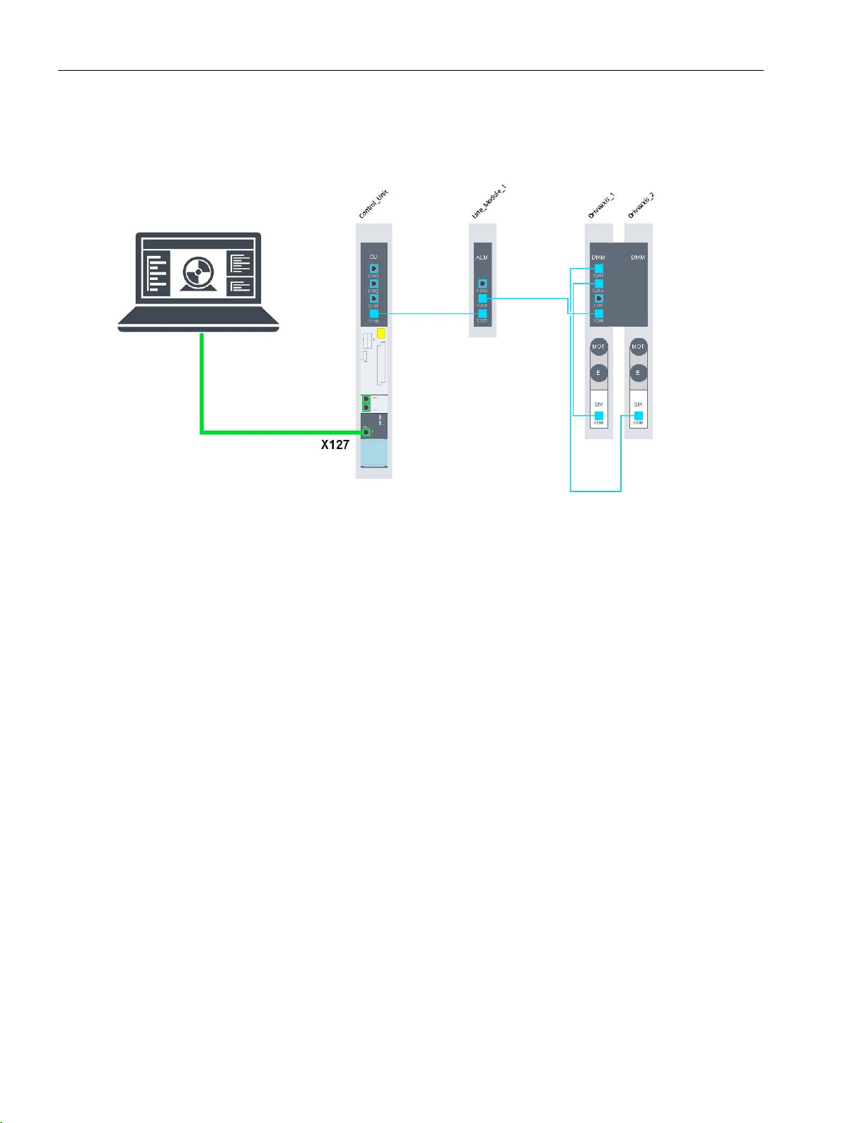
A typical configuration example comprises the following components:
Before the drive can be configured in Startdrive, install the hardware and wire the
components.
● Drive unit, SINAMICS S120 CU320-2 PN Control Unit
● Line Module (infeed)
● Motor Module (single or double)
● Motors and measuring systems (encoders)
Typical DRIVE-CLiQ wiring to connect the components is shown in the configuration
example. The PG/PC with Startdrive is connected to the Control Unit via Ethernet. You can
use interfaces X127 or X150 to establish the connection.
In the next step, in Startdrive you create a new project and configure the hardware.
Getting Started SINAMICS S120 in Startdrive
Getting Started, 02/2017
9
Page 10
Configuring the hardware in the offline mode
Video, configuration example for SINAMICS S120 CU320-2 PN
2.2
Creating a new project
Portal and project view
This is how you create a new project in the portal view
2.2 Creating a new project
Figure 2-1 Configuration example for SINAMICS S120 with Startdrive via X127
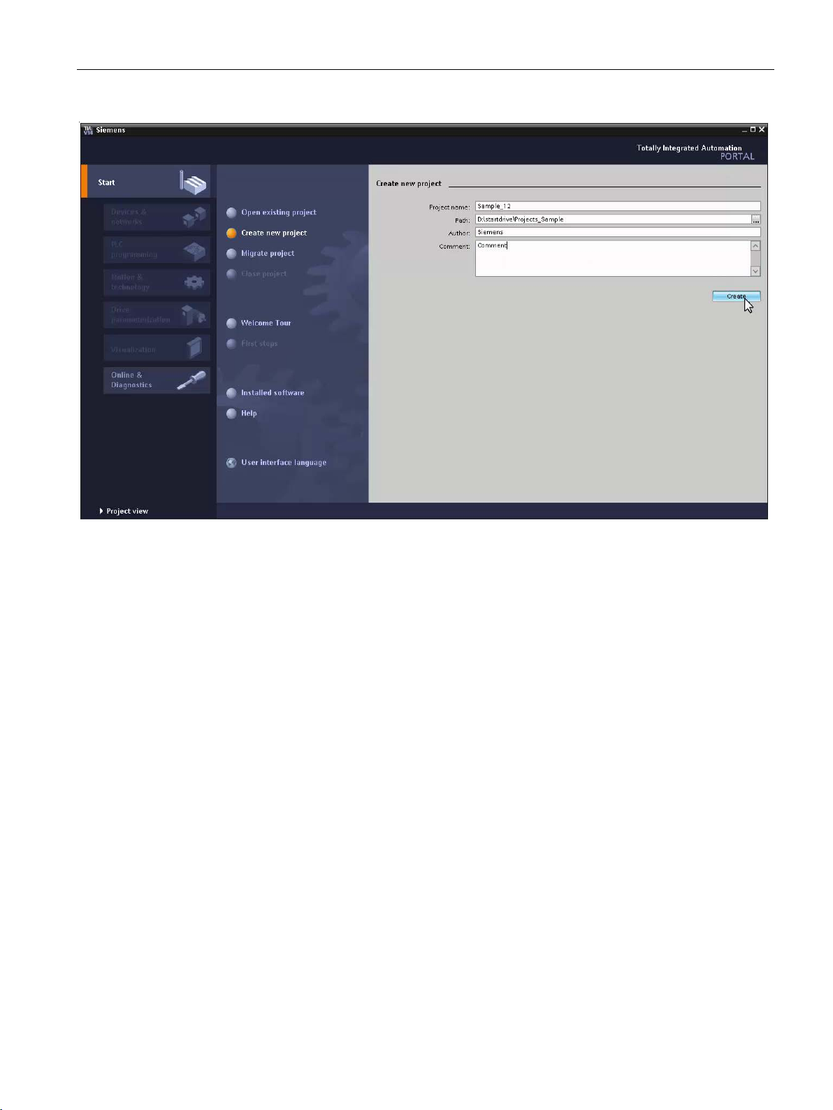
After opening Startdrive, you will be in the portal view of the TIA Portal. The portal view
offers a task-oriented view of the tools, and provides the basic functions for the individual
task areas. The project view is another view. This provides a complete view of all
components of the project, e.g. hardware and programs, and is used for all project tasks.
1. Open Startdrive in the portal view
2. Click "Create new project".
3. Enter a name under "Project name" and select the "path" for saving the project.
4. Enter additional project information under "Author" and "Comment".
5. Confirm with "Create". The project is created.
6. Click on "Project view" to change from the portal view to the project view.
In the project view you carry out additional steps for configuring and commissioning.
Getting Started SINAMICS S120 in Startdrive
10 Getting Started, 02/2017
Page 11
Configuring the hardware in the offline mode
2.3
Inserting a SINAMICS S120 drive unit
Description
This is how you insert the drive unit into the project view
This is how you insert the drive unit into the network view
2.3 Inserting a SINAMICS S120 drive unit
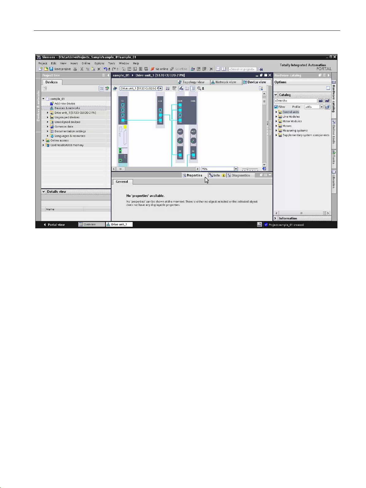
Figure 2-2 02-02-create-new-project-out
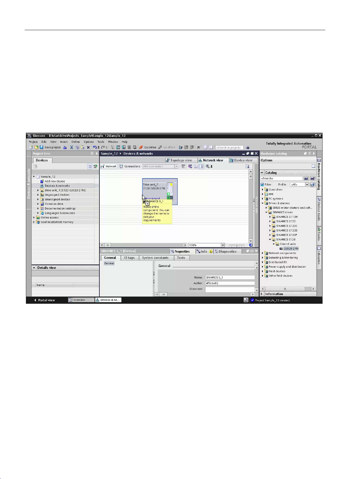
You now insert the hardware in the project that has been created and configure it. The drive
unit must first be inserted. To do this you can use two versions.
1. Double-click "Add new device" in the project tree.
2. In the dialog that is displayed, click on "Drives" – and select the SINAMICS S120 CU3202 PN drive.
3. The drive is inserted, and the "Device view" tab is displayed.
In this view, you insert additional components using drag & drop from the hardware
catalog.
1. Double-click on "Devices & networks" in the project tree.
2. Change to the "Network view".
Getting Started SINAMICS S120 in Startdrive
Getting Started, 02/2017
11
Page 12
Configuring the hardware in the offline mode
2.4
Inserting a Line Module (infeed)
Description
2.4 Inserting a Line Module (infeed)
3. You can insert the drive from the hardware catalog. Drag the SINAMICS S120 CU320-2
PN and drop into the network view.
4. A plus symbol is displayed at the mouse pointer if the component can be inserted at the
actual position.
5. A forbidden sign signals that this component cannot be inserted in this position.
6. The drive is inserted.
In the "Device view" you insert additional components using drag & drop from the
hardware catalog.
Figure 2-3 02-06-drive-device-insert
After the Control Unit (Drive) you insert a Line Module. Only the three basic types – Active,
Basic and Smart Line Modules – are listed in the hardware catalog. These are first specified
in an additional step.
Getting Started SINAMICS S120 in Startdrive
12 Getting Started, 02/2017
Page 13

Configuring the hardware in the offline mode
This is how you insert a Line Module and specify it
Note
Specifying components
The placeholder components must first be specified. The pro
Section
2.4 Inserting a Line Module (infeed)
1. In the hardware catalog, open the "Line Modules" folder.
2. Click on the Line Module, e.g. "Active Line Modules", and drag-and-drop to the device
view.
The Line Module is inserted as unspecified component, and shown with a white
background.
cedure is described in
Specifying placeholder components (Page 14).
Figure 2-4 02-07-insert-line-modules
Getting Started SINAMICS S120 in Startdrive
Getting Started, 02/2017
13
Page 14

Configuring the hardware in the offline mode
2.5
Specifying placeholder components
2.5.1
Specifying placeholder components
Description
Placeholder components are:
This is how you specify a placeholder component using a Line Module as example
Note
Filtering products
You can display a reduced selection of products in the "Inspector window" by using the filter
function. Section "
2.5 Specifying placeholder components
Only non-specified components are listed in the hardware catalog. After being inserted in the
device view, these are only placeholders; a specific product for the component must be
specified in a second step.
● Line Modules
● Motor Modules
● Motors
● Measuring systems
1. Click in the component on the white surface. This white color indicates that the
component has still not been specified. The selected area is marked and has a blue
border.
2. The selection of a possible product for the marked component is displayed in the
"Inspector window" in "Properties > General".
3. Based on the article number, select a product by clicking on this product in the "Selection"
column.
4. The surface that was previously white changes to dark gray, indicating that the product
has been assigned to the placeholder.
Filtering products (Page 15)" describes how you can filter products.
Getting Started SINAMICS S120 in Startdrive
14 Getting Started, 02/2017
Page 15

Configuring the hardware in the offline mode
2.5.2
Filtering products
Description
This is how you filter products according to technical features
This is how you filter products using a search text
2.5 Specifying placeholder components
Figure 2-5 02-04-specifying-components
You can display a reduced selection of products in the "Inspector window" by using the filter
function. For example, you can filter for parts of an article number – or specific technical
features of the products.
1. In the column that you wish to filter, click on the symbol next to <Filter>. In the selection
that is displayed, select the filter value, e.g. the rated current.
2. Click on the filter symbol in the first column. The filter is selected, and only products are
displayed that correspond to the filter criteria.
1. In the text field <Filter>, double-click on the required column. Enter a search text, e.g.
parts of an article number. A list of hits is displayed.
2. Click on one of these products ("hits") – or click in the first column on the filter symbol in
order to display all products that correspond to the filter criteria.
Getting Started SINAMICS S120 in Startdrive
Getting Started, 02/2017
15
Page 16

Configuring the hardware in the offline mode
This is how you delete the filter
2.6
Inserting a Motor Module
Description
2.6 Inserting a Motor Module
1. In the "Selection" column, click on the filter symbol. The active filter is deleted, and all of
the available products displayed.
Figure 2-6 02-05-filtering-products
You insert Motor Modules from the hardware catalog as non-specified component.
Getting Started SINAMICS S120 in Startdrive
16 Getting Started, 02/2017
Page 17

Configuring the hardware in the offline mode
This is how you insert a Motor Module and specify it
Note
Specifying components
The placeholder components must first be specified. The procedure is described in
Section "
2.7 Inserting a motor
1. In the hardware catalog, open the "Motor Modules" folder.
2. Click on the Motor Module, e.g. "Double Motor Module", and drag & drop to the device
view.
The Motor Module is inserted as unspecified component, and shown with a white
background.
3. Specify the Motor Module. Select the appropriate product based on the article number
under the "Properties > General" tab of the inspector window.
Specifying placeholder components (Page 14)".
You insert the motor in the next step.
Figure 2-7 02-08-insert-motor-module
Getting Started SINAMICS S120 in Startdrive
Getting Started, 02/2017
17
Page 18

Configuring the hardware in the offline mode
2.7
Inserting a motor
Description
This is how you insert a motor and specify it
Note
Specifying components
The placeholder components must first be specified. The procedure is described in
Section "
2.7 Inserting a motor
You insert motors from the hardware catalog as non-specified component. Depending on the
motor, an encoder and encoder evaluation are also automatically inserted.
1. In the hardware catalog, open the "Motor" folder. You can insert DRIVE-CLiQ,
synchronous and induction motors.
2. Click on a motor, e.g. "1PH7 induction motors", and using drag & drop place this in the
lower section of Motor Modules. "MOT" is inserted as placeholder.
The motor is inserted as unspecified component, and shown with a white background.
3. Specify the motor. Select the appropriate product based on the article number under the
"Properties > General" tab of the inspector window. Depending on the motor type,
encoder and encoder evaluation are inserted. In this particular example, this is only the
motor.
Specifying placeholder components (Page 14)".
In the next step you will insert an encoder and the encoder evaluation.
Getting Started SINAMICS S120 in Startdrive
18 Getting Started, 02/2017
Page 19

Configuring the hardware in the offline mode
2.8
Inserting a measuring system
Description
This is how you insert an encoder and encoder evaluation
2.8 Inserting a measuring system
Figure 2-8 02-09-insert-motor
For several motors, encoder and encoder evaluation of the measuring system are already
defined, and are inserted as default. For motors without encoder, you must still insert an
encoder and encoder evaluation.
1. In the hardware catalog, open the "Measuring systems" folder.
2. Click on an encoder, e.g. "SSI encoder", and using drag & drop place this in the section
below the motor. The placeholder for an encoder (E) and the encoder evaluation (SM)
are inserted as non-specified components.
Getting Started SINAMICS S120 in Startdrive
Getting Started, 02/2017
19
Page 20

Configuring the hardware in the offline mode
Note
Specifying components
The placeholder components must first be specified. The procedure is described in
Section "
2.9
Changing DRIVE-CLiQ connections
Description
2.9 Changing DRIVE-CLiQ connections
3. Specify the encoder and encoder evaluation based on the article number in the "Encoder
data selection" or "Encoder evaluation" in the "Inspector window".
Specifying placeholder components (Page 14)".
4. If you wish to configure a second encoder, then repeat the previous steps.
This step completes the hardware configuration. You can configure optional system
components, such as terminal boards and terminal modules. When doing this, refer to the
Startdrive online help.
Figure 2-9 02-08-insert-measuring-system
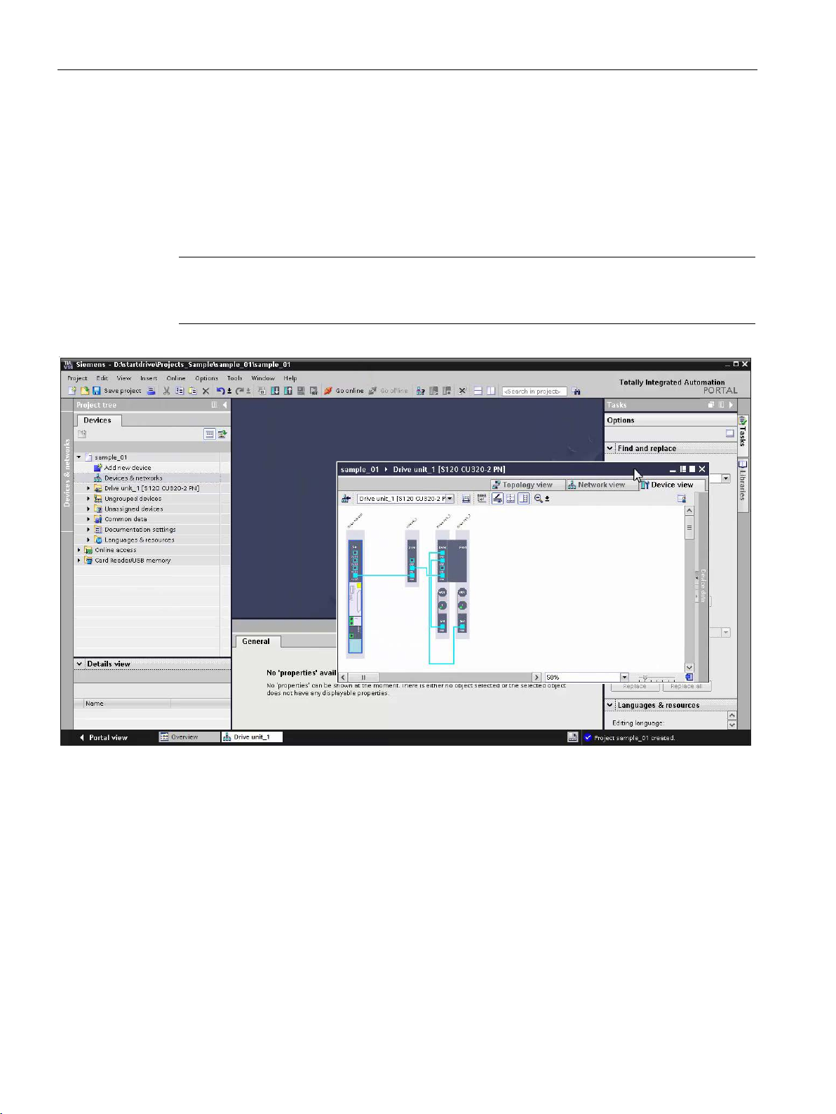
Configure the drive line-up in the "Device view". You drag & drop the components from the
hardware catalog and edit the DRIVE-CLiQ connections.
Getting Started SINAMICS S120 in Startdrive
20 Getting Started, 02/2017
Page 21

Configuring the hardware in the offline mode
This is how you insert the components and change the DRIVE-CLiQ connection
2.9 Changing DRIVE-CLiQ connections
1. Drag & drop the components into the device view.
2. A DRIVE-CLiQ connection is automatically established after inserting. You can delete the
standard connection. With the left-hand mouse key pressed, you can establish your own
DRIVE-CLiQ connection between the DRIVE-CLiQ ports.
Figure 2-10 02-03-insert-components
Getting Started SINAMICS S120 in Startdrive
Getting Started, 02/2017
21
Page 22

Configuring the hardware in the offline mode
2.9 Changing DRIVE-CLiQ connections
Getting Started SINAMICS S120 in Startdrive
22 Getting Started, 02/2017
Page 23

online
3
3.1
Going online
Description
3.2
Ethernet connection via X127
Description
This is how you connect SINAMICS S120 using Startdrive
Figure 3-1 Overview – Startdrive online connection to the drive unit
Using the "Accessible devices" function, Startdrive provides the option of going online to the
drive. The drive unit can either be connected to the PC via Ethernet (X127) or via
PROFINET (X150).
In the following you will learn how to connect the drive unit to the PG/PC, identify it using
"Accessible devices" and go online.
Using the programming device (PG/PC), the Control Unit can be commissioned via the
integrated Ethernet interface X127. This interface is only intended for commissioning and
service, and not for operationally controlling the drive.
● Connect the Ethernet interface of the PG/PC with the commissioning interface X127 of
the Control Unit.
The IP address of the X127 interface is assigned as follows when first supplied:
– IP address: 169.254.11.22
– Subnet: 255.255.0.0
Getting Started SINAMICS S120 in Startdrive
Getting Started, 02/2017
23
Page 24

Connecting the drive unit with the PC and going online
3.3
Display accessible devices
Description
This is how you display connected drives via accessible devices
3.3 Display accessible devices
Figure 3-2 PG/PC connected via X127 to SINAMICS S120 CU320-2 PN
Using accessible devices, you can display all connected and interfaced drive units, which are
connected with a PG/PC interface. In "Online access" under the required interface, search
for accessible devices to obtain a first overview and and to test the cabling/wiring. The drive
unit is displayed with the corresponding IP address if the connection has been correctly
established to the drive unit.
1. Open the "Online access" folder in the project tree.
2. Open the folder of the interface to which the drive unit is connected.
3. Double-click "Update accessible devices" below the interface.
The interface is scanned for connected devices. All network devices that are accessible
via the selected interface are displayed with name and IP address.
4. Double-click "Online & diagnostics" below the drive unit that has been found. A new
window is shown in the working area.
Details about the drive unit, such as IP address, device name etc., are displayed in the
window. You can change these or restore the drive unit to the factory settings.
Getting Started SINAMICS S120 in Startdrive
24 Getting Started, 02/2017
Page 25

Connecting the drive unit with the PC and going online
3.4
Go online via Ethernet IE (X127)
Description
This is how you go online via Ethernet interface 127
3.4 Go online via Ethernet IE (X127)
Figure 3-3 03-03 accessible-device
You can connect to the drive unit online via commissioning interface X127. In the TIA Portal,
you have already configured the hardware, and the drive unit is connected via Ethernet
interface X127. Prior to this, you must have already checked whether the drive is identified
using the "Accessible devices" function.
1. Click on the drive unit in the project tree or the device view. The "Go online" button is
activated.
2. Click on "Go online". A dialog opens.
3. Select the type of the PG/PC interface. In the example, "PN/IE".
4. Select the PG/PC interface of your PC.
5. Define the "Connection to interface/subnet". This is the X127 of the CU320-2 PN for
Ethernet/IE.
Getting Started SINAMICS S120 in Startdrive
Getting Started, 02/2017
25
Page 26

Connecting the drive unit with the PC and going online
3.4 Go online via Ethernet IE (X127)
6. Click "Start search" to search for the drive units connected to the selected interface.
The drive units that are found are displayed in the overview.
7. Select the drive unit and click on "Connect".
The connection to the drive unit is established. In the online mode, the title bar of the
device view turns orange. There is no error if all of the components are displayed with a
green checkbox.
The next time that you go online, the settings made are automatically applied – and the "Go
online" dialog is no longer displayed.
Figure 3-4 03-04-go-online-via Ethernet-X127
Getting Started SINAMICS S120 in Startdrive
26 Getting Started, 02/2017
Page 27

4
4.1
Traversing the motor from the drive control panel
Description
This is how you control the drive from the control panel
NOTICE
The motor rotates
Using the drive control panel, you can carry out the first function test of the drive and control
and monitor individual drives. You control the drive by entering values. Depending on the
particular operating mode, these include speed setpoints, for example.
To do this, Startdrive must be connected online with the drive.
1. In the project tree, click on "Commissioning" below the drive that you wish to control. The
window is opened in the work area.
2. In the secondary navigation of the commissioning, open the "Control panel" entry. If there
is no online connection, then Startdrive attempts to establish a connection. When an
online connection has been established, the bar in the header area is shown in color. The
control elements are grayed-out, with the exception of the "Activate" button. The
remaining control elements only become active after you have activated the control panel
and set the enables.
3. At the control panel, activate master control and the infeed and set the drive enables and
the operating mode.
Depending on the configuration, the enables can already be assigned – as is the case in
this example. The motor is ready and is operated in the closed-loop speed control mode.
Observe the safety instructions in the manual before you make the motor rotate.
4. Switch the motor on.
5. Enter a value for the speed.
6. By clicking the "Forward" or "Backward" buttons you can make the motor rotate. The
motor accelerates to the specified speed. The actual values are displayed.
7. Click "Stop" to stop the drive, switch off the motor, reset the drive enables and relinquish
master control.
Getting Started SINAMICS S120 in Startdrive
Getting Started, 02/2017
27
Page 28

Using the drive control panel
4.1 Traversing the motor from the drive control panel
Figure 4-1 04-01-traverse-motor-with-drive-control-panel
Getting Started SINAMICS S120 in Startdrive
28 Getting Started, 02/2017
Page 29

5
5.1
Function and parameter views
Description
Offline and online
A parameterization editor with a function and a parameter view is available to parameterize
the drive. They are described in more detail in this section. You parameterize the drive using
screen forms with a graphic user interface in the function view. The parameter view shows a
tabular overview of the parameters available for the device. You can change the parameter
values.
The function and parameter view are available offline and online. In the offline mode, you
parameterize the drives in the project and the values are also saved in the project. In the
online mode, you change the parameters directly in the drive – and the values are saved in
the drive.
You must use the "Load to device" function to save the offline project in the device. You
must use the "Load to device" function to transfer the online values into the project.
Figure 5-1 05-01-function-and-parameter view
Getting Started SINAMICS S120 in Startdrive
Getting Started, 02/2017
29
Page 30

Parameterizing the drive
5.2
Assigning parameters in the function view
Description
This is how you work with the function view
5.2 Assigning parameters in the function view
You edit the most important parameters in a clearly organized, graphical user interface in the
function view. The screen forms are based on function diagrams that map the functions in
signal flow diagrams. The signal flow is from left to right.
1. In the project tree, double-click on "Parameters" below the drive or the Control Unit.
2. In the work area, click on the "Function view" tab.
The secondary navigation for calling the function-oriented screen forms is in the left-hand
area of the function view.
3. Assign the signals for the inputs/outputs similar to the real terminal connections. Simply
select the terminal signal from the displayed list.
4. You can parameterize the functions in the screen forms with the aid of a graphic support.
5. In addition to the secondary navigation, you can toggle between the individual screen
forms of the function view using buttons.
6. You are supported by help screens when entering values.
Figure 5-2 05-02-parameterizing-function-view
Getting Started SINAMICS S120 in Startdrive
30 Getting Started, 02/2017
Page 31

Parameterizing the drive
5.3
Online function view
Description
How to go online with the function view
5.3 Online function view
If you are connected online with the drive, then in the function view you can change
parameter values directly in the drive. The input fields of the parameters that you can change
online are displayed in orange.
1. Connect Startdrive online with the drive. The input fields that can be changed are
displayed in orange.
2. Parameter changes in the online view are only effective in the drive itself.
3. To permanently save the data in the drive unit, click the "Permanently save data for all
drive units" button. The data is saved on the memory card.
4. If you want to transfer the changes to the offline project, you must first disconnect the
online connection, and then upload the changes to the project.
Figure 5-3 05-03-function-view-online
Getting Started SINAMICS S120 in Startdrive
Getting Started, 02/2017
31
Page 32

Parameterizing the drive
5.4
Parameterizing in the parameter view
Description
This is how you work with the parameter list
5.4 Parameterizing in the parameter view
The parameter view transparently shows the parameters available for the device.
Parameters are sorted according to specific topics so that it is easy to find them. Parameters
that can be changed have a light gray background.
1. Click on the "Parameter view" tab in the work area.
2. From the drop-down list define which parameters should be displayed with which access
level, e.g. standard for typical parameters.
3. Click the parameter in the "Value" column that you wish to change.
4. Select a value from the list or enter a value and confirm it with the enter key.
5. To display the online help, click the parameter and open the online help for the parameter
using the tooltip that is displayed.
Figure 5-4 05-04-parameterizing-parameter-view
Getting Started SINAMICS S120 in Startdrive
32 Getting Started, 02/2017
Page 33

Parameterizing the drive
5.5
Online parameter view
Description
This is how you go online with the parameter view
5.5 Online parameter view
If you are connected online with the drive, then in the parameter view you can change
parameter values directly in the drive. The input fields of the parameters that you can change
online are displayed in orange.
1. Switch to online mode in the parameter view. The input fields that can be changed are
displayed in orange.
2. Parameter changes in the online view are only effective in the drive itself.
3. To permanently save the data in the drive unit, click the "Permanently save data for all
drive units" button. The data is saved on the memory card.
4. If you want to transfer the changes to the offline project, you must first disconnect the
online connection, and then upload the changes to the project.
Figure 5-5 05-05-parameter-view-online
Getting Started SINAMICS S120 in Startdrive
Getting Started, 02/2017
33
Page 34

Parameterizing the drive
5.5 Online parameter view
Getting Started SINAMICS S120 in Startdrive
34 Getting Started, 02/2017
Page 35

6
6.1
Diagnostics overview
Description
6.2
Device diagnostics
Description
The TIA Portal with integrated Startdrive offers a range of diagnostic options. You can
identify the drive and see the most important data using general diagnostics. In the event of
a error, faults and alarms are displayed with proposed solutions. For targeted diagnostics
you can record signal sequences with the trace function and analyze them. A brief overview
of the diagnostic functions is provided in the following.
Getting Started SINAMICS S120 in Startdrive
Getting Started, 02/2017
A series of diagnostic options are available to you in the online mode.
35
Page 36

Diagnostics and troubleshooting
This is how you work with the device diagnostics
6.2 Device diagnostics
1. Go online with the drive unit. Unique symbols for the diagnostic status are displayed in
the TIA Portal. You can find these in the project tree, in the device view and in the device
overview, for example. The diagnostics status is transferred to higher-level objects, e.g.
drive units or control systems. As a consequence, a motor fault is also displayed at the
Control Unit. Errors are shown in red.
2. You can obtain more information about the significance of the individual symbols in the
online help – this will then allow you to localize faults.
3. Faults, disturbances, alarms and messages are displayed in the "Inspector window"
under the "Diagnostics" tab.
4. The online help with counter-measures is displayed by clicking on the question mark for
the particular message.
5. After the fault has been resolved, you can acknowledge messages that are still active
using the acknowledge button. The acknowledge messages are deleted from the
overview.
Figure 6-1 06-02-device-diagnostics
Getting Started SINAMICS S120 in Startdrive
36 Getting Started, 02/2017
Page 37

Diagnostics and troubleshooting
6.3
Diagnostics topology error
Description
This is how you diagnose typical topology errors
First error scenario: DRIVE-CLiQ connection not inserted at a port of a drive object
Note
If several ports are marked in red, starting from the left and moving to the right, check all
error descriptions using the tooltip.
6.3 Diagnostics topology error
All DRIVE-CLiQ components of the drive line-up are shown in the device view. If the DRIVECLiQ wiring of the offline configuration is different to the actual wiring, then these errors are
displayed in the device view. You obtain a brief description of the error at the tooltip. A
target-actual alignment of the DRIVE-CLiQ wiring is performed online.
After going online, the drive objects (DO) that are ready are displayed with a green
checkmark in the device view. However, topology errors, which are designated with red at
the DRIVE-CLiQ connection, can also be present. You can find three typical error scenarios
in the following.
1. Click on the port marked in red at the first drive object (in this particular case, the Control
Unit) and show the tooltip. The tooltip shows the target connection in comparison to the
currently available connection – and provides a brief error description. In the example,
there is no connection between port X103 of the Control Unit and port X500 of the TM31.
2. Display the tooltip of the partner port marked in red at the TM31. The error describes that
there is no connection at port X500 of the TM31.
3. Check the DRIVE-CLiQ wiring at the real hardware. Insert the connection according to
the target topology.
4. Acknowledge the active errors in the message view.
The ports in the device view are shown in blue if the actual and target topology match
after the error has been resolved and the message acknowledged.
Getting Started SINAMICS S120 in Startdrive
Getting Started, 02/2017
37
Page 38

Diagnostics and troubleshooting
Second error scenario: Two ports involved in a DRIVE-CLiQ connection interchanged
Note
When switching over connections in the online mode, more errors can be briefly
displayed, as certain objects can no longer be accessed. You only see the updated view
without any errors once the target topology has been complete
Third error scenario: A DRIVE-CLiQ connection inserted at the port of an incorrect drive
object
Note
If the device
briefly to the network view.
6.3 Diagnostics topology error
1. Check the port marked in red at the first drive object.
Typically, it is displayed that no connection should be inserted. However, in the actual
topology, there is a connection to another port. In the example, a connection exists from
X101 to X200 of the Line Module, which is not configured.
2. Check the partner port of the other drive object, marked in red – in this case, the Line
Module.
It is displayed that a connection should exist to X100 – however it goes to X101. When
connecting up, both ports were interchanged.
3. Change over the connection at the first drive object from X101 to X100. This means that
the actual and target topology are identical, and the ports are shown in blue.
ly wired and is accessible.
If more complex topology errors are active, resolve them step-by-step – and observe the
subsequent changes in the device view. As a result of the error combination, not all errors
can be directly analyzed and displayed.
1. Check the port at the first drive object that is red, in the example, the Single Motor
Module.
The tooltip displays that a connection, which is not configured, is inserted at port X201.
2. Withdraw the connection from port X201. The port is displayed as being error-free after
the device view has been updated. In addition, faults are displayed at the Double Motor
Module and at the Sensor Module.
view is not automatically updated after changing the wiring, simply change
3. Check the red ports at the Motor Module and at the Sensor Module.
The tooltip displays that the Sensor Module is not inserted at the Double Motor Module.
4. Insert the connection and acknowledge active messages.
The topology is displayed as being error-free.
Getting Started SINAMICS S120 in Startdrive
38 Getting Started, 02/2017
Page 39

Diagnostics and troubleshooting
6.3 Diagnostics topology error
Figure 6-2 06-03-diagnostics-topology-error
Getting Started SINAMICS S120 in Startdrive
Getting Started, 02/2017
39
Page 40

Diagnostics and troubleshooting
6.3 Diagnostics topology error
Getting Started SINAMICS S120 in Startdrive
40 Getting Started, 02/2017
 Loading...