

Page 1
Siemens AG
RF30-EM
Codoor
Configuration Manual
Page 2

Liefermöglichkeiten und technische Änderungen vorbehalten.
Data and design subject to change without notice. / Supply subject to availability.
© 2010 Copyright by Siemens AG
Wir behalten uns alle Rechte an diesem Dokument und an dem in ihm dargestellten Gegenstand vor. Der Empfänger erkennt diese Rechte
an und wird dieses Dokument nicht ohne unsere vorgängige schriftliche Ermächtigung ganz oder teilweise Dritten zugänglich machen oder
außerhalb des Zweckes verwenden, zu dem es ihm übergeben worden ist.
We reserve all rights in this document and in the subject thereof. By acceptance of the document the recipient acknowledges these rights
and undertakes not to publish the document nor the subject thereof in full or in part, nor to make them available to any third party without our
prior express written authorization, nor to use it for any purpose other than for which it was delivered to him.
About this document
This configuration manual contains instructions for installation, setup,
configuration and oper ation of RF30-EM.
For more information about the wh ole wireless access control system see Si-
Pass/Bewator Entro wir el ess installation manual.
Trade mark
All products or company names mentioned in this manual for purposes of identification or description could be trademarks or registered trademarks of their respective owners.
Contacting us
If you have questions or s ug ge s t i ons regarding the produ ct or this documentation,
please contact your local SIEMENS representative.
Siemens AG
I BT DE FS SP
D-76187 Karlsruhe
You can also visit our Web site at:www.buildingtechnologies.siemens.com/.
Training courses
Siemens AG provides training courses for all products.
Page 3

3
Siemens AG
04.2010
Contents
1 Service description................................................................... ............5
2 Safety ................................................................... ..................................5
2.1 Target group............................................................................................5
2.2 General safety precautions......................................................................5
3 Standards and guidelines.....................................................................6
3.1 EU directives...........................................................................................6
4 Technical data ....................... ................................................................7
5 Details for ordering...............................................................................8
6 Package contents............................................................................. .....8
7 Description of Equipment.....................................................................9
7.1 Stand-alone mode...................................................................................9
7.2 System mode......................................... .................................................9
7.3 Mounting ...................................................................... ...........................9
7.4 Wireless communication..........................................................................9
7.4.1 Antennae.............................................................. .................................10
7.5 Power down and activation....................................................................10
7.6 Keypad.............. ....................................................................................10
7.7 LED status when connecting................................................................. 11
7.8 LED status in service mode...................................................................11
7.9 LED Status at battery warning...............................................................11
7.10 Buzzer................................................................................. ..................12
7.11 Unlock a door........................................................................................12
8 Change Administrator code...................................................... ..........13
8.1 Present Administrator code is known.....................................................13
8.2 Present Administrator code is not known...............................................14
9 System mode................................ .......................................................15
9.1 Activate System mode.................................................. .........................15
9.2 Service mode........................................................................................16
9.2.1 Check signal strength - A30..................................................................16
9.2.2 Check link reliability – A31............................. ........................................16
9.2.3 Reboot the RF30-EM – A32 ..................................................................16
9.2.4 Reconnect the network – A34................................................................16
10 Mounting..............................................................................................17
10.1 Technical details.................................................... ................................17
10.2 Fitting RF30-EM to the door .................................. ................................18
10.2.1 Distance between units.........................................................................19
10.2.2 Test mechanical function of RF30-EM...................................................19
10.2.3 Offline mode..........................................................................................19
10.3 Change batteries...................................................................................19
10.4 Adjust the PIR sensor.......................................................... ..................20
11 Stand-alone mode...............................................................................21
11.1 Add a card..................................................... ........................................21
11.1.1 Adding a card by reading it....................................................................21
11.1.2 Adding a card by entering its number....................................................22
11.1.3 Log on contiguous series of card s.........................................................23
11.2 Cancel a card........................................................................................24
11.2.1 Cancel a card by reading it....................................................................24
Page 4

4
Siemens AG
04.2010
11.2.2 Cancel a card by entering its number....................................................24
11.3 Set Group code.....................................................................................25
11.3.1 Enter Group code..................................................................................25
11.3.2 Change Group code..............................................................................26
11.3.3 Delete Group code........................................................................... ..... 26
11.4 Lock/unlock door...................................................................................27
11.5 Disable/enable buzzer...........................................................................27
12 Erase memory......................................................................................28
13 Operation.............................................................................................29
13.1 Leaving the premises ............................................................................29
13.2 Automatic resetting................................................................................29
13.3 Access blocking.....................................................................................29
13.4 Backup power supply ............................................................................29
14 Command overview.............................................................................30
15 Troubleshooting............................................................................. .....32
16 Glossary ...............................................................................................33
17 Keyword index.....................................................................................34
Page 5

Service description
5
Siemens AG
04.2010
1 Service description
RF30-EM is a Scandinavian style Codoor. It can be used as a wireless system
component or as a Stand-alone unit.
2 Safety
2.1 Target group
Target readers Qualification Activity Condition of the
product
Installer Technical training for
building or electrical
installations.
Installs the product,
individual components
of the product or replacement parts.
Components of the
product are not yet
installed or need to be
replaced or modified.
Operational startup
personnel
Technical training for
building or electrical
installations.
Special knowledge of
the device/system is
required.
Puts the product into
operation for the first
time, or changes the
existing configuration.
The product is installed
but not yet configured,
or the existing configuration is to be changed.
Service personnel Technical training for
building or electrical
installations.
Special knowledge of
the device/system is
required.
Checks the product at
regular intervals to
ensure that it is in good
working order, services
the device or system
and repairs it or expands and upgrades the
system.
Product already in use
and requiring servicing.
2.2 General safety precautions
Read the general safety precauti o ns before operating the device.
Keep this document for reference.
Always pass this document on toget her with the product.
Please also take into account any additional country -s pe ci fi c , lo cal safety
standards or regulations concerning project planning, operation and disposal of
the product.
Damage to the device due to electrostatic discharge (ESD)
Always use wrist straps or similar connected to earth.
Damage due to unsuitable mounting location
The device should only be used for indoor applications.
Page 6
Standards and guidelines
6
Siemens AG
04.2010
3 Standards and guidelines
3.1 EU directives
This product complies wit h the r eq ui rements of the European Dire cti ves. The EU
declaration of conformity is available from:
Siemens AG
I BT DE FS SP
76187 Karlsruhe, Germany
EU directives 1999/5/EC R&TTE: “Radio and telecommunications terminal
equipment”
Compliance with the Eur o pe an Directive 1999/5/EC has been proven by testing
according to the following standards:
Electromagnetic compatibility EN 301 489-1
EN 301 489-17
EMC immunity of alarm systems EN 50130-4
Safety EN 60950-1
Radio requirements EN 300 330-2
EN 300 328
Page 7

Technical data
7
Siemens AG
04.2010
4 Technical data
RF30-EM
Operating voltage Two Lithium 9V type 6LR61 batteries (not in-
cluded).
For a safe function we strongly recommend the use
of our batteries Ultralife UL9V with 9V, 1200 mAh
and sustaining minimum 400 mA peak current.
Operational time Approx. one year
Card technology EM4102 125 kHz
Card capacity In System mode (online): Set by SiPass/Bewator
Entro
In System mode (offline): 250 cards (100 priority
and 150 peronal cards)
In Stand-alone mode: 250 cards
Card read distance 1 to 3 cm (approx.)
Frequency band 2.4 GHz
Indicators 3 x LED (red/yellow/green)
1 x buzzer
Operating temperature 0 to +50 °C
Environment Indoor use only
IP rating IP30
Colour Stainless steel
Dimensions (W x H x D) 285 x 64 x 59 mm
Weight 0.76 kg
Approval CE
NOTE
Lithium batteries must be used because they provide the foll owi ng advan tage s:
The capacity is constant throughout battery life.
Longer battery life reduces the environmental impact as fewer batteries are needed.
Battery storage life can be up to ten years.
Page 8

Details for ordering
8
Siemens AG
04.2010
5 Details for ordering
Type Order No. Designation Weight
RF30-EM GBI:31-118
Codoor
0.76 kg
6 Package contents
Check that you have the followin g parts before discarding the packing materials:
1 x RF30-EM (batteries excluded).
4 extension sleeves for handle nipples (use only one pair, M4 or M5).
1 x reinforcing spring.
1 x reinforcing spring holder.
Page 9

Description of Equipment
9
Siemens AG
04.2010
7 Description of Equipment
7.1 Stand-alone mode
In Stand-alone mode you have only one RF30-EM controlling one door.
1. Set the Administrator code. See section 8 Change Administrator code.
2. Program cards and Group co des. See section 11 Stand-al on e mo d e.
7.2 System mode
In System mode you can have more than one RF30-EM integrated in a whole
access control system controlled by the SiPass/Bewator Entro software.
Programming can only be done via the SiPass/Bewator Entro software.
NOTE
Do not mount two RF30-EM units back to back on one door. They cannot both control the door latch.
1. Set the Administrator code. See section 8 Change Administrator code.
2. Activate System mode. See section 9 System mode.
3. Check for communication betw ee n th e RF30 and the SiPass/Bewator Entro
system. See section 9.2 Service mode
4. Mount the RF30-EM. See section 10 Mo unting.
Back to Stand-alone mode
Erase the system settings and return to the factory default condition. See
section 12 Erase me mory.
7.3 Mounting
The RF30-EM may be fitted on most doors with handle operated ASSA modular
type mortise locks.
When fitted, the external handle is inoperable until a valid card or code is entered.
The internal handle is not affected and will retract the latch bolt as required.
7.4 Wireless communication
The RF30-EM communicates with a host controller via a radio net work. Thus the
RF30-EM operates as a wireless reader in an SiPass/Bewator Entro system. All
communication takes place via a Private Area Network (PAN) where either a SR35i
or a router RF9 transmits information via radio to/from the RF30-EM.
Page 10
Description of Equipm en t
10
Siemens AG
04.2010
7.4.1 Antennae
The card reader antenna is integrated in the upper part of the keypad, so cards
and other tags should be presented to the keypa d.
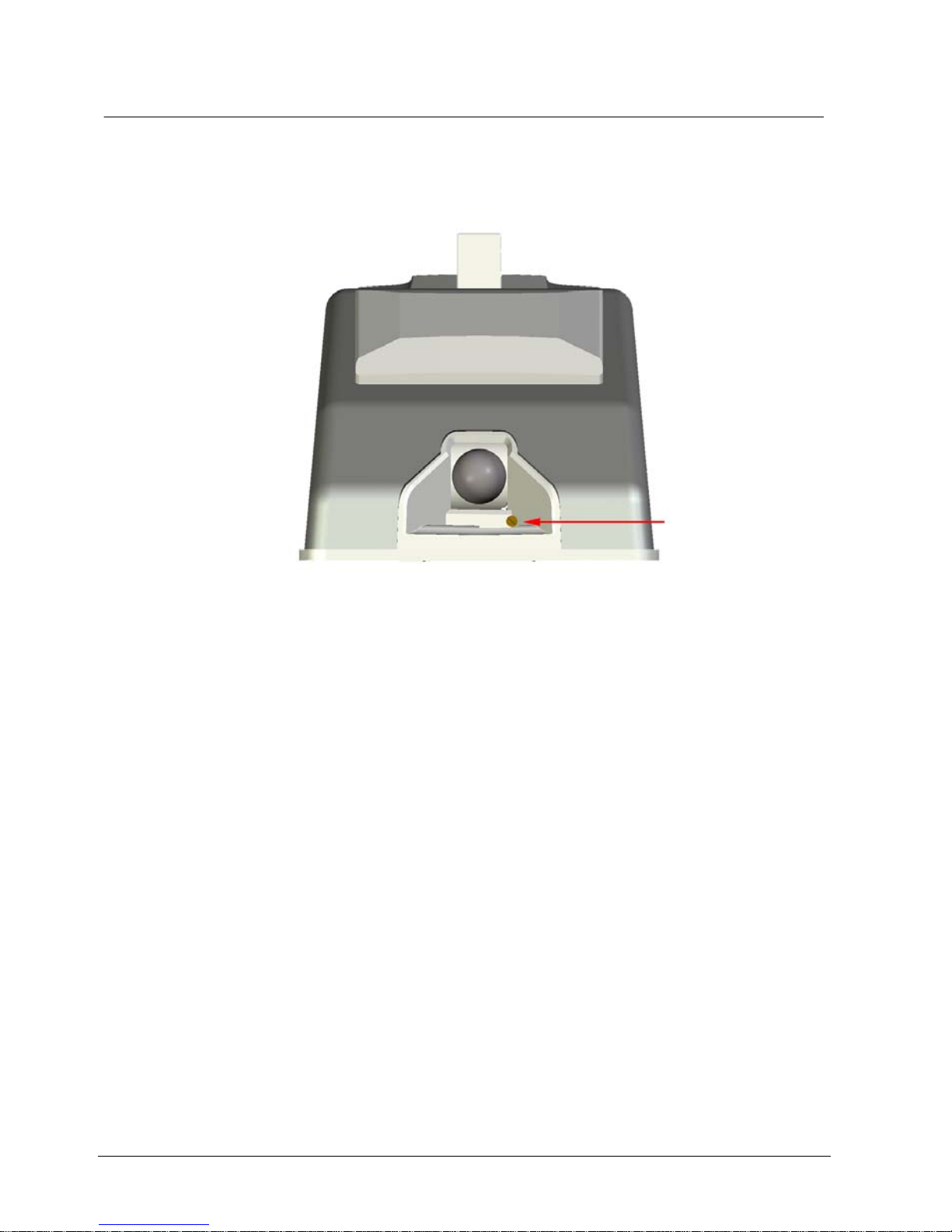
The network antenna is locate d in the grey plastic housing on the lo wer face of the
RF30-EM.
7.5 Power down and activation
Normal operational use of the RF30-EM will consume power from the batteries.
When the RF30-EM is not in use, the power consump ti on is reduced to a minimum
to save batteries .
PIR sensor
A passive infra-red (PIR) sensor “wakes up” the reader when it detects a person
close to the RF30-EM. The RF30- EM is thus ready to provide acce ss to the door
via card and/or Group code/PIN. See section 10.4 Adjust the PIR sensor.
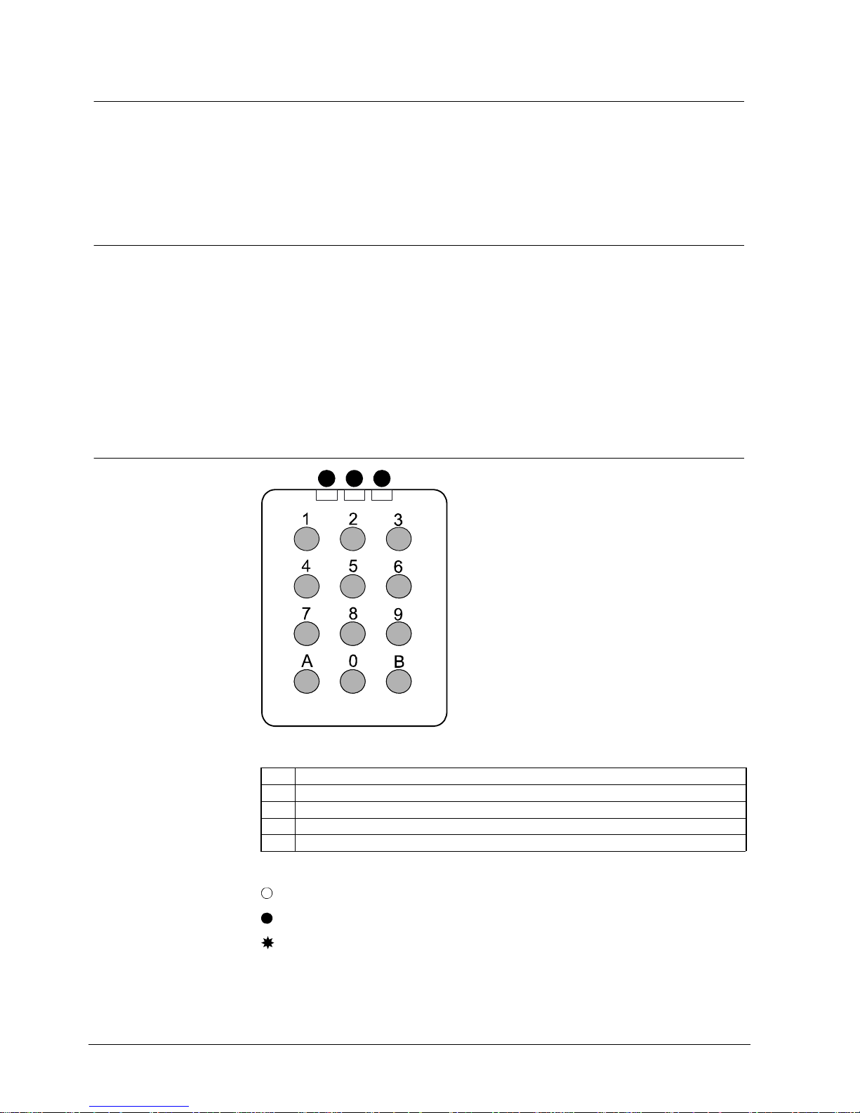
7.6 Keypad
1 2 3
Fig. 1 Keypad RF30-EM
Red LED.
Yellow LED.
Green LED.
0-9 Are used for entering codes and/or programming.
A/B Are used only for programming.
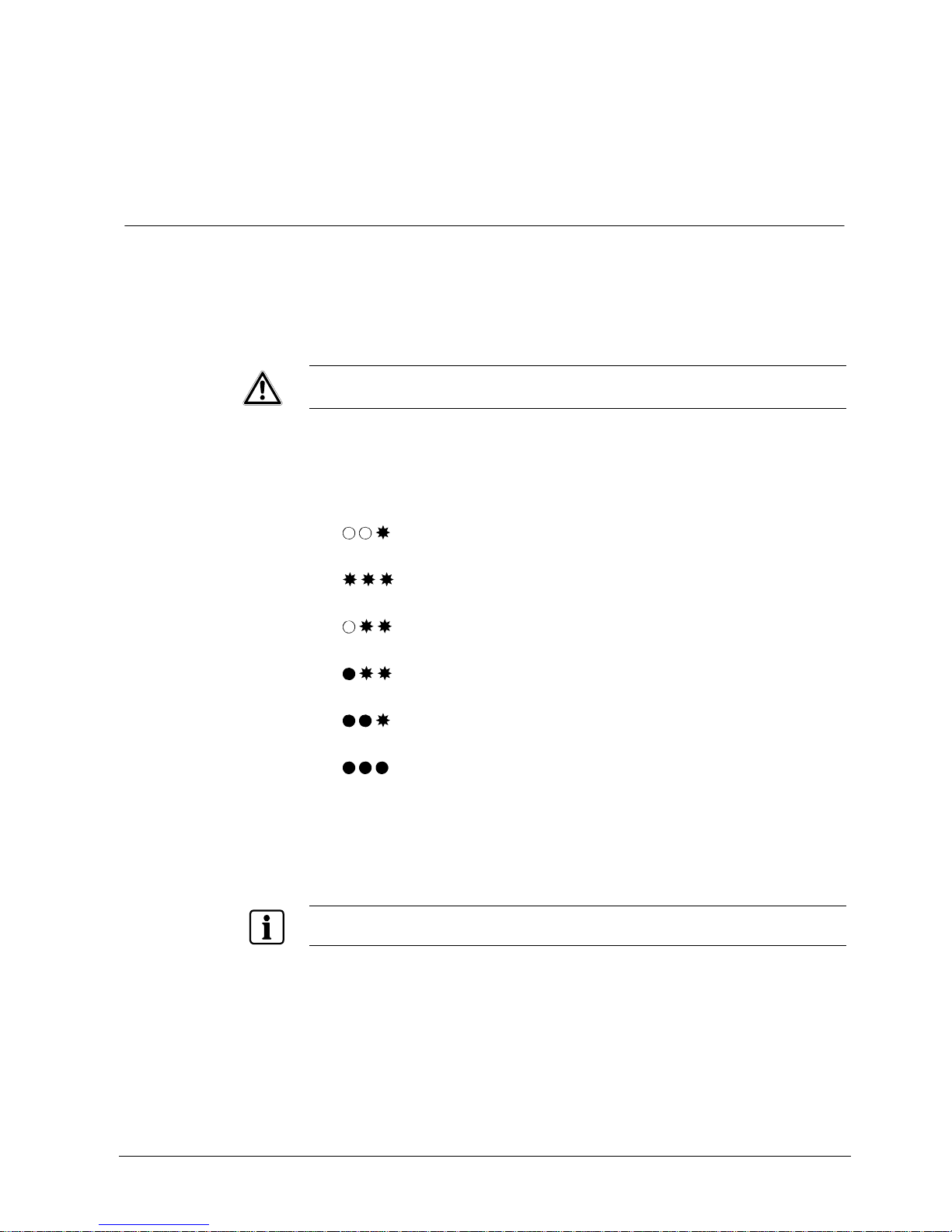
In this manual three symbols illustrate how the LEDs are used:
= OFF
= ON
= Flashing
Page 11
Description of Equipment
11
Siemens AG
04.2010
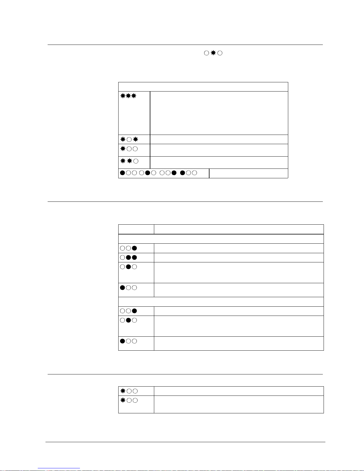
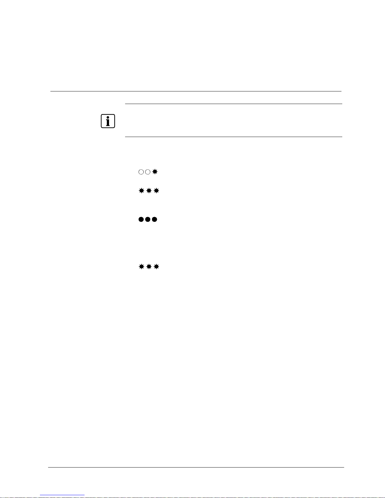
7.7 LED status when connecting
When the yellow is LED flashing (e g due to wrong segment ID or the
radio connection link is down, press 0 for at least two seconds for detailed error
codes.
Detailed error codes
Address collision
Another RF30-EM might have the same address.
Too many doors in one segment.
Address number is not allowed in this segment. This is depending
on the SR35i range (4/8/16/32). E.g. in a SR35i/4 you can’t use
the Address “5”. See installation manual SiPass/Bewator Entro
Wireless.
Wrong installation key.
For safety reasons the entry is blocked for a while. The installation
key has been entered wrong three times in a row.
System limit of RF30-EM in the system reached. See installation
manual SiPass/Bewator Entro Wireless.
, , , ,…
Connecting to the network.
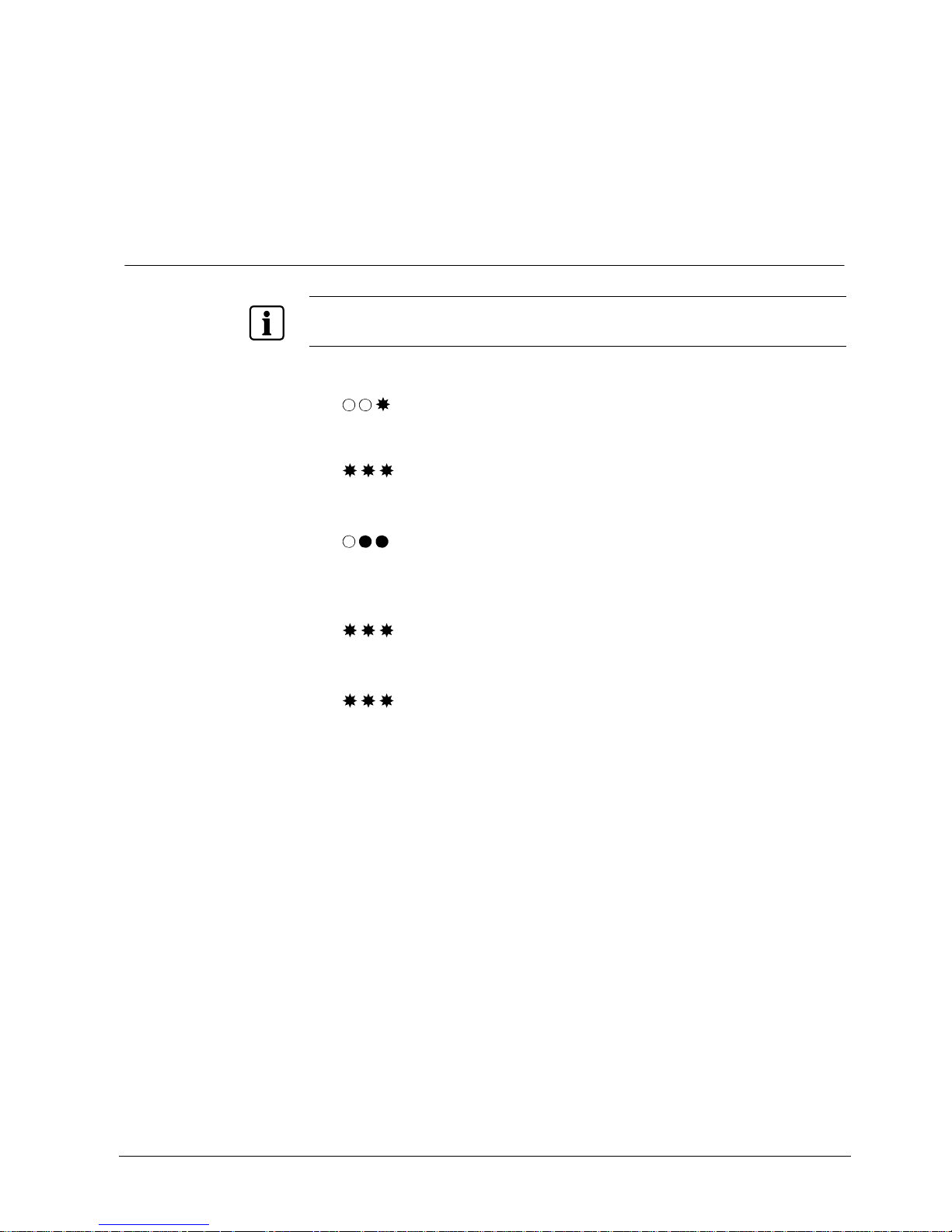
7.8 LED status in service mode
To enter the Service mode see section 9.2 Servic e mode .
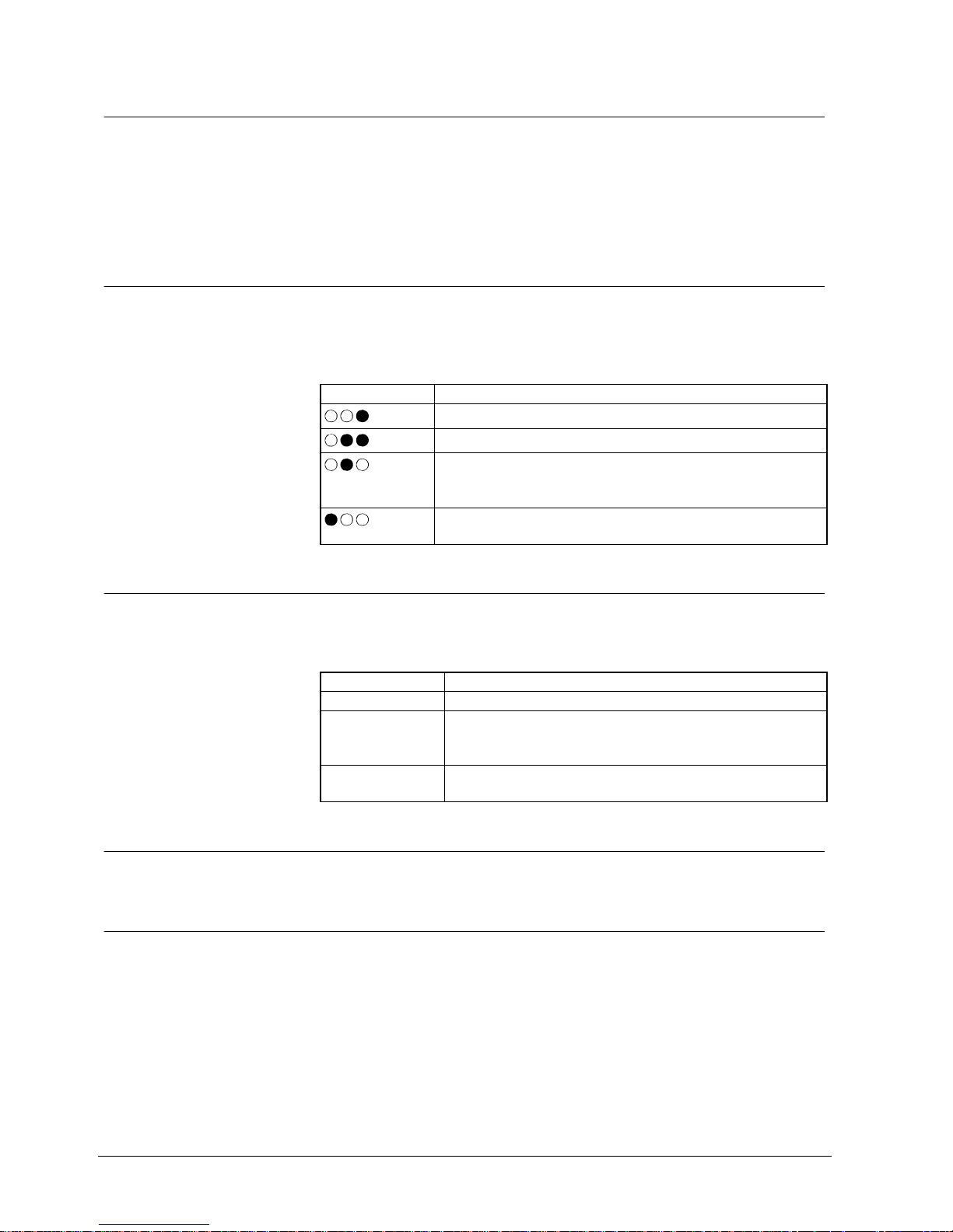
LEDs Declaration
Service mode - Signal strength (command A30)
Signal strength excellent.
Signal strength sufficient.
Signal strength OK.
Recommendation
Rel ocate the router.
Signal strength weak.
Rel ocate the router.
Service mode - Link reliability (command A31)
Link reliability OK. Sending and receiving messages.
One or more messages lost.
Recommendation
Rel ocate the router.
Link unreliability. Messaging took more than 0.7 s.
Rel ocate the router.
7.9 LED Status at battery warning
First warning level for low battery: Flashing LED and a delay of the unlocking.
Second warning level for low battery: Fast flashing LED on each key press. Door
can be opened only with Administrator code. Loosing connection to the network,
entering Offline mode.
Page 12

Description of Equipm en t
12
Siemens AG
04.2010
7.10 Buzzer
RF30-EM also incorporates a buzzer to confirm each key press (if required).
The buzzer also sounds to confirm successful programming.
7.11 Unlock a door
In Stand-alone mode either a card or a code can be used to unlock the door. The
use of a card provides higher security.
In System mode, a ca rd with corresponding code can be us ed.
Page 13

Change Administrator code
13
Siemens AG
04.2010
8 Change Administrator code
8.1 Present Administrator code is known
NOTE
The Administrator code cannot be the same as the code 112186 to erase the memory.
See section 12 Erase memory.
If you are in administrator mode and don’t press a key the device will automatically leave the
administrator mode after 30 seconds.
RF30-EM is delivere d wi t h the default Administrator code set as 112233.
1. Press B.
2. Enter the 6-digit Administr a tor co de.
3. Press A27.
The buzzer sounds a confirm tune.
4. Enter a new 6-digit Administr a tor co de.
The buzzer sounds a confirm tune.
5. Verify by entering the same Administrator code again.
RF30-EM exits at the Administrator mode.
6. Make a note of the Administrator code.
Page 14
Change Administrator code
14
Siemens AG
04.2010
8.2 Present Administrator code is not known
NOTE
The Administrator code cannot be the same as the code 112186 to erase the memory.
See section 12 Erase memory.
If you are in administrator mode and don’t press a key the device will automatically leave the
administrator mode after 30 seconds.
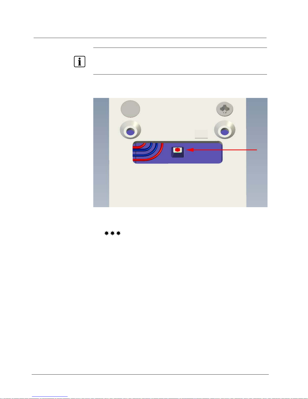
1. Remove the RF3 0- EM from the door.
2. Quickly press the reset button on the back of the RF30-EM.
Fig. 2 Reset button on the back
The buzzer sounds a confirm tune.
3. Enter the desir e d 6- digit Administrator code.
The buzzer sounds a confirm tune.
4. Verify by entering the same Administrator code again.
The buzzer sounds a confirm tune.
If the second input doesn’t match the first in put the buzzer will sound a error
tone and the Administrator code will not be changed.
5. Make a note of the Administrator code.
Page 15
System mode
15
Siemens AG
04.2010
9 System mode
9.1 Activate System mode
Starting in Stand-alone mode, three parameters must be entered to set the
RF30-EM in System mode:
4-digit Segment ID
2-digit Address
8-digit Installation key
CAUTION
Remember to change the Administrator code for safety reasons
If the battery is low the door can be opened with the default Administrator code.
1. Change the Administrator code. See section 8 Change Administrator code.
2. Check in the SiPass/Bewator Entro software which Segment ID, Address and
installation key is used in the SR35i.
3. Press B.
4. Enter the 6-digit Administr a tor co de.
5. Enter A80.
6. Enter the 4-digit Segm ent ID.
7. Enter the 2-digit Address. (01 - 32)
8. Enter the 8-digit Installation key.
9. Press A.
The RF30-EM will operate in System mode. If any other key than A is pre sse d
the RF30-EM returns to Stand-alone Administrator mode.
If any of these steps is not performed within 20 seconds the RF30-EM returns to
Administrator mode.
NOTE
If you make errors in steps 6 to 8, press any other key than A in step 9 and start over from step 5.
Page 16
System mode
16
Siemens AG
04.2010
9.2 Service mode
1. To enter the service mode quickly press key B followed by a long press on
key B and wait until the buzzer confirm.
2. Enter the 6-digit Administrator code
The commands A30, A31, A32 or A34 can then be performed.
3. To leave this mode press B.
9.2.1 Check signal strength - A30
The A30 command displays the signal strength. It will proceed for 5 minutes or until
a key press or card use. Note that although the green LED lit the command A31
should be performed to confirm a reliable data transmission.
LED Description
Signal strength excellent.
Signal strength sufficient.
Signal strength OK.
Recommendation
Relocate the router.
Signal strength bad.
Relocate the router.
9.2.2 Check link reliability – A31
The command A31 displays the reliability of the data transmission. It will proceed
for 5 minutes or until a key pr ess or car d us e .
Buzzer Description
Continuous tones. Link reliability OK. Sending and receiving messages.
Non continuous
tones.
One or more messages lost.
Recommendation
Relocate the router.
Error tone. Link unreliability. Messaging took more then 0.7 s.
Relocate the router.
9.2.3 Reboot the RF30-EM – A32
The command A32 performs a reboot of the firmware in the RF30-EM.
9.2.4 Reconnect the network – A34
The command A34 should be performed if e g a router has bee n a dded to the system. The system tries to reconnect the RF30-EM to the Segment Controller.
Page 17
Mounting
17
Siemens AG
04.2010
10 Mounting
10.1 Technical details
NOTE
Do not mount two RF30-EM units back to back on one door. They cannot both control the latch.
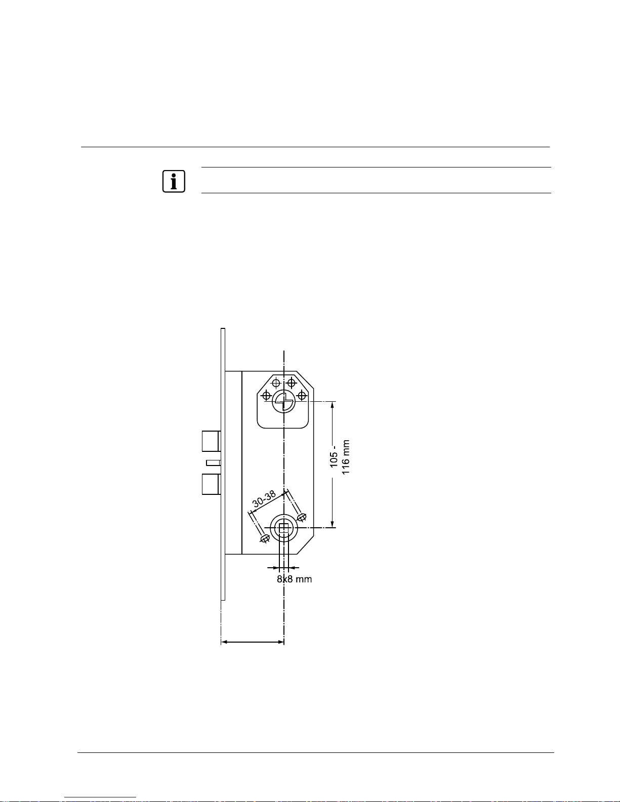
RF30-EM is suitable for most doors with handle-operated mortise locks.
The distance between the centre of the handle and the cen tre of the cylinder
should be between 105 – 116 mm.
Latchbolt function.
The handle must have an 8 mm square spindle.
The handle’s fixing holes should be at 30 – 38 mm centres (diagonal).
The RF30-EM can be used with a variety of lock s such as ASSA 8561 or 565.
The backset should be 70 mm.
Backset = 70 mm
Fig. 3 RF30-EM door mounting
Page 18
Mounting
18
Siemens AG
04.2010
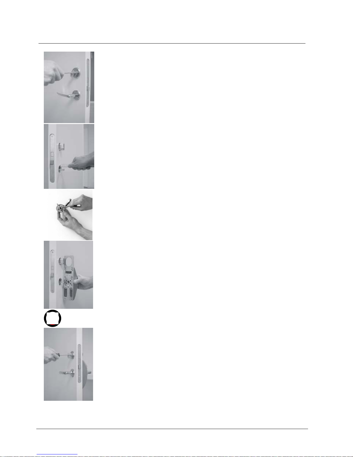
10.2 Fitting RF30-EM to the door
1. Check that the Administrator code has been set. See section 8 Change Ad-
ministrator code.
2. Make sure you have the following tools handy:
– Screwdriver for door ha ndle and cylinder ring screws.
– Hacksaw for trimming lever handle spindle.
3. Remove the cylinder ring and door handle from the door by loosening the four
screws. See figure 1.
4. Ensure that the handle spindle does not project more than 20 mm on the
outside of the door. If the spindle is too long, push it through into the handle
on the inside. If this cannot be done, cut the spindle to th e right length. See
figure 2.
5. Prepare the han dle by extending the scr ews with the supplied ext en s i o n
sleeves (M4 or M5). See figure 3.
6. Place the RF30 on the outside of the door wi th the handle attached , and pa s s
the lever handle spindle through the square hole. See fi gure 4.
7. Ensure that the red mark on the follower point downwards. See figure 5.
8. Tighten the fo ur previously loosen e d screws to the nipples (the sc rews for the
handle first). These should be just firm. Over-tightening may distort the lock
structure so that it jams. See figure 6.
9. Test the mechanical function of the RF30-EM. Se e se cti o n 10.2.2 Test
mechanical function of RF30-EM.
1
2
3
4
5
6
Page 19

Mounting
19
Siemens AG
04.2010
10.2.1 Distance between units
For reliable operation, the distance betwee n the SR35i and the RF30-EM units
must not exceed 25 metres. In that case a RF9 router/amplifier must be installed.
You can read more about this in the installation guid e supp l i e d with the RF9. Note
that electrical interference or noise may also reduce the working range of the
wireless link. See SiPass/Bewator Entro Wireless intstallation manual.
10.2.2 Test mechanical function of RF30-EM
It must always be possible to open the d oor from the inside.
Check that the PIR sensor will detect a person and activate the electronics. This
means that nothing limits the detection area of the s en sor .
The handle on the outside should not be engaged, and should not open the door
until the correct card/code is entered.
When the correct card/code is entered, the handle on the outside should activate
the lock, but only once. As the handle is released, it should again disengage.
If the correct card/code is entered but the handle is not pressed do wn, the RF30-
EM should automatically disengage the handle after about 4 seconds.
The handle on the outside must not be jam med in any position, and should
spring back up completely after being pressed down.
10.2.3 Offline mode
In normal operation the ho st system controls the validit y of t he cards. If the
RF30-EM loses contact with the system it will operate offline in offli ne mode. The
yellow LED will flash slowly, if the RF30-EM has never had a connection to the
system.
In this mode the RF30-EM accepts up to 250 cards stored in internal memory.
These are known as Priority Cards and are identical to the priority cards in
SiPass/Bewator Entro. The priority cards are regularly downloaded from the
system when the RF30-EM is on-line (see section 7.7 LED status when
connecting.
If the red LED flashes and the buz zer sounds when reading a car d this means that
the card is not valid in offline mode.
10.3 Change batteries
When the unit’s batteries run flat the RF30 -EM will cease to re lease the latch so
the unit should be fitted with cylinder override. The lock ha s a ba ckup power supply
that will allow the door to be opened a limited number of times, but the batteries
should be replaced as soon as the low battery warning is notic ed. See sections
7.7 LED status, 11.5 Disable/enable buzzer and 13.4 Backup power supply. The
card memory of the RF30-EM is retained while the ba tt er i es are flat and while the
batteries are being replaced.
1. Remove the RF30-EM from the door.
2. Remove the two batteries fro m t he rectangular shaped holes on the lower part
of the back of the unit (to power off the unit).
3. Always change both bat teries at the same time. See secti o n 4 Technical data.
4. Re-mount the RF30-EM.
Page 20
Mounting
20
Siemens AG
04.2010
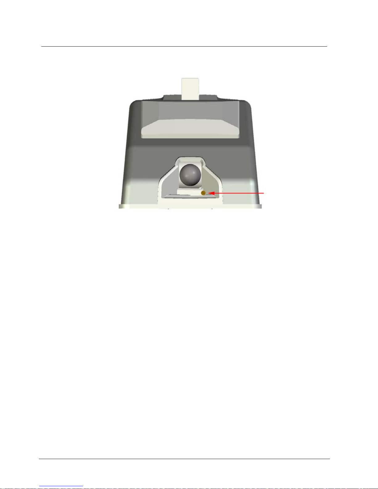
10.4 Adjust the PIR sensor
Depending on the environmen t it could be necessary to adjust the PIR sensor.
Remember to do this carefully and keep the sensor while the screw is adjusted.
Fig. 4 RF30-EM – PIR sensor and screw to adjust the PIR sensor
Minimize the PIR sensor radius
The door is located in a busy environment for example stores or corridors.
1. Turn the screw anticlo ckwise.
The sensor moves down.
Extend the PIR sensor radius
The door will be opened from the side instead of the front.
1. Turn the screw to the right.
The sensor moves up.
Page 21
Stand-alone mode
21
Siemens AG
04.2010
11 Stand-alone mode
11.1 Add a card
11.1.1 Adding a card by reading it
NOTE
If you have entered the wrong Axx command (e g in step 3 below) you can abort the command and
exit to Administrator mode by pressing A again.
1. Press B.
2. Enter the 6-digit Administrator code. See section 8 Change Administrator
code.
3. Press A01.
The buzzer sounds a confirm tune.
- or -
If the memory is full, the buzzer will sound an error tune and return to
Administrator mode.
4. Present the card at the RF30-EM.
The buzzer sounds a confirm tune.
5. Add the next card, if req ui r e d.
Page 22

Stand-alone m ode
22
Siemens AG
04.2010
11.1.2 Adding a card by entering its number
NOTE
If you have entered the wrong Axx command (e g in step 3 below) you can abort the command and
exit to Administrator mode by pressing A again.
1. Press B.
2. Enter the 6-digit Administrator code. See secti o n 8 Cha ng e Ad ministrator
code.
3. Press A03.
The buzzer sounds a confirm tune.
If the memory is full, the buzzer will sound an error tune and return to
Administrato r mode.
4. Enter the last 8-digits of the card number on the keypad.
The buzzer sounds a confirm tune.
5. Add the next card, if required.
Page 23

Stand-alone mode
23
Siemens AG
04.2010
11.1.3 Log on contiguous series of cards
NOTE
If you have entered the wrong Axx command (e g in step 3 below) you can abort the command and
exit to Administrator mode by pressing A again.
1. Press B.
2. Enter the 6-digit Administrator code. See section 8 Change Administrator
code.
3. Press A04.
The buzzer sounds a confirm tune.
- or -
If the memory is full, the buzzer will sound an error tune and return to
Administrator mode.
4. Enter the the card number of the first card (last 8-digits) in the series.
The buzzer sounds a confirm tune.
5. Enter the card number of the last card (last 8-digits) in the series.
The buzzer sounds a confirm tune.
LED 1 flashes red continuously as the cards are logged on.
- or -
If the memory is full or the first number is greater than the second number, the
buzzer will sound an error tune and return to Administrator mode.
Page 24

Stand-alone m ode
24
Siemens AG
04.2010
11.2 Cancel a card
11.2.1 Cancel a card by reading it
NOTE
If you have entered the wrong Axx command (e g in step 3 below) you can abort the command and
exit to Administrator mode by pressing A again.
1. Press B.
2. Enter the 6-digit Administrator code. See sec ti o n 8 Cha ng e Ad ministrator
code.
3. Press A14.
The buzzer sounds a confirm tune.
4. Present the car d at the RF30-EM.
The buzzer sounds a confirm tune.
5. Cancel the next card, by presenting them at the RF30-EM.
11.2.2 Cancel a card by entering its number
NOTE
If you have entered the wrong Axx command (e g in step 3 below) you can abort the command and
exit to Administrator mode by pressing A again.
1. Press B.
2. Enter the 6-digit Administrator code. See sec ti o n 8 Cha ng e Ad ministrator
code.
3. Press A16.
The buzzer sounds a confirm tune.
4. Enter the card number on the keypad.
The buzzer sounds a confirm tune.
5. Cancel the next card, by entering the card number at the keypad.
Page 25

Stand-alone mode
25
Siemens AG
04.2010
11.3 Set Group code
11.3.1 Enter Group code
CAUTION
Remember that when using Group codes, the overall security is lowered
because codes can easily be distributed.
NOTE
If you have entered the wrong Axx command (e g in step 3 below) you can abort the command and
exit to Administrator mode by pressing A again.
In parallel with card readi ng four 4-digit Group codes can be set. Each Group code
needs to be assigned a group numb er. (1-4)
1. Press B.
2. Enter the 6-digit Administrator code. See section 8 Change Administrator
code.
3. Press A21.
The buzzer sounds a confirm tune.
4. Enter the desired 1- di git group number (1-4).
The buzzer sounds a confirm tune.
5. Enter the desired 4- di git Group code.
The buzzer sounds a confirm tune.
6. To set another Group code, follow steps 4-5.
Page 26

Stand-alone m ode
26
Siemens AG
04.2010
11.3.2 Change Group code
1. Press B.
2. Enter the 6-digit Administrator code. See sec ti o n 8 Cha ng e Ad ministrator
code.
3. Press A21.
The buzzer sounds a confirm tune.
4. Enter the desired 1-digit group number (1-4).
The buzzer sounds a confirm tune.
5. Enter the desi r e d 4- digit Group code.
The buzzer sounds a confirm tune.
The existing Group code will be over-written.
6. To change another Group code, follow steps 4-5.
11.3.3 Delete Group code
1. Press B.
2. Enter the 6-digit Administrator code. See sec ti o n 8 Cha ng e Ad ministrator
code.
3. Press A21.
The buzzer sounds a confirm tune.
4. Enter the desired 1-digit group number (1-4).
The buzzer sounds a confirm tune.
5. Enter 0000.
The buzzer sounds a confirm tune.
6. To delete another Group code, follow steps 4-5.
Page 27

Stand-alone mode
27
Siemens AG
04.2010
11.4 Lock/unlock door
Unlock door
1.
Press A1A.
The buzzer sounds a confirm tune.
2. Present a valid card at the RF 30-EM.
The buzzer sounds a confirm tune.
3. Open the door.
Lock door
1.
Press A0A.
The buzzer sounds a confirm tune.
2. Present a valid card at the RF 30-EM.
The buzzer sounds a confirm tune.
The door is now locked.
RF30-EM returns to normal operation.
11.5 Disable/enable buzzer
The default setting is for the buzzer to sound as each key is pressed. Change if
silent operation is required.
1. Press B.
2. Enter the 6-digit Administrator code. See section 8 Change Administrator
code.
3. Press A65.
The buzzer sounds a confirm tune.
4. To enable press 1.
- or To disable press
0.
The buzzer sounds a confirm tune.
The RF30-EM returns to the Administrator mode.
5. Press B to leave the Adminis t rator mode.
Page 28

Erase memory
28
Siemens AG
04.2010
12 Erase memory
In cases where the RF30-EM is moved to another door (with new users), old
cards/code s should remain. The best way to ensure this is to erase the memor y.
1. Remove the RF3 0- EM from the door.
2. Press and hold the reset button on the back of the RF30-EM for at least 2
seconds.
The buzzer sounds a confirm tune.
Fig. 5 Reset button on the back
3. Press 112186.
The buzzer sounds a confirm tune.
The buzzer sounds a warning tone to alert that y ou ar e ab ou t to erase the
memory.
4. Press 112186.
The buzzer sounds a confirm tune.
The memory is erased.
After approximately eight seconds the RF30-EM re-starts.
The RF30-EM is in Stand-alone mode with the following default settings:
– Administrator code: 112233
– The Administrator code can also be us e d for unlocking the door.
– All memory locations are empty.
– Buzzer on.
Page 29

Operation
29
Siemens AG
04.2010
13 Operation
13.1 Leaving the premises
The RF30-EM’s mechanic al locking device only affects th e out si d e door handle.
The door can always be opene d from the inside as usual.
13.2 Automatic resetting
RF30-EM has two separate resetting systems to return the lock to the locked
position after a code has been entered. The lock is reset mechanically each time
the door handle is used during access. The lock is also electronically reset if the
handle is not used within 4 s econds after a card is used or a cod e b ei n g en tered.
This provides security against unauthorised access, since the RF30-EM can never
accidentally be left in the unlocked position.
13.3 Access blocking
To thwart attempts to obtain an access code by trial and error, RF30-EM
incorporates a blocking function to disable the unit after 12 false key presses (three
successive incorrect 4-digit codes). The unit remains blocked until 2 correct codes
are entered successively.
13.4 Backup power supply
When the batteries are running low. RF30-EM will flash the red LED for 3 seconds
before opening the lock. The lock has a backup power supply that will allow the
door to be opened 200 times or a time of two weeks has passed.
After the door has been opened 200 times the only way to open the door is with the
Administrator code.
Page 30

Command overview
30
Siemens AG
04.2010
14 Command overview
Command 1. 2. 3. 4. 5. 6. 7.
Change Administrator code
Change Administrator
code
(Present Administrator
code is known)
Press B. Enter the
6-digit Administrator code.
Press A27. Enter a new
6-digit Administrator code.
Verify by
entering the
same Administrator code
again.
Make a note
of the Administrator code.
Change Administrator
code
(Present Administrator
code is not known)
Remove the
RF30-EM
from the door.
Press the
reset button
on the back of
the RF30-EM.
Enter the
desired 6-digit
Administrator
code.
Verify by
entering the
same Administrator code
again.
Make a note
of the Administrator code.
System mode
Activate System mode Press B. Enter the
6-digit Administrator code.
Enter A80. Enter the
4-digit Segment ID.
Enter the 2digit Address.
(01 - 32)
Enter the
8-digit Installation ID.
Press A.
Service mode
Enter Service mode Press quickly
on B.
Press long on B Buzzer
sounds
Enter the
6-digit Administrator code.
Use command A30,
A31, A32 or
A34.
Check signal strength Press A30
Check link reliability Press A31
Reboot unit Press A32
Reconnect network Press A34
Leave Service mode Press B.
Normal mode
Check status Press 0 for
two seconds.
LEDs displays status
Green LED =
OK
Otherwise se
section 7.7
LED status
when
connecting
Stand-alone mode
Adding a card by reading it Press B. Enter the
6-digit Administrator code.
Press A01. Present the
card at the
RF30-EM.
Adding a card by entering
its number
Press B. Enter the
6-digit Administrator code.
Press A03. Enter the card
number on
the keypad.
Log on contiguous series
of cards
Press B. Enter the
6-digit Administrator code.
Press A04. Enter the card
number of the
first card (last
8-digit) in the
series.
Enter the card
number of the
last card (last
8-digit) in the
series.
Cancel a card by reading it Press B. Enter the
6-digit Administrator code.
Press A14. Present the
card at the
RF30-EM.
Cancel a card by entering
its number
Press B. Enter the
6-digit Administrator code.
Press A16. Enter the card
number on
the keypad.
Enter Group code
Change group code
Press B. Enter the
6-digit Administrator code.
Press A21. Enter the
desired 1-digit
group number
(1-4).
Enter the
desired 4-digit
Group code.
Delete Group code Press B. Enter the
6-digit Administrator code.
Press A21. Enter the
desired 1-digit
group number
(1-4)
Enter 0000.
Page 31

Command overview
31
Siemens AG
04.2010
Command 1. 2. 3. 4. 5. 6. 7.
Unlock door Press A1A. Present a
valid card at
the RF30-EM.
Lock door Press A0A. Present a
valid card at
the RF30-EM.
Disable buzzer Press B. Enter the
6-digit Administrator code.
Press A65. To enable
press 0.
Enable buzzer Press B. Enter the
6-digit Administrator code.
Press A65. To disable
press 1.
Erase memory
Erase memory Remove the
RF30-EM
from the door.
Press the
reset button
on the back of
the RF30-EM.
Press
112186.
Press
112186.
Page 32

Troubleshooting
32
Siemens AG
04.2010
15 Troubleshooting
Symptom Remedy
Lock does not open when card/Group code/PIN is
entered.
Check that the correct card/Group code/PIN
has been entered.
The cards may be injured.
Make sure the handle is not pressed down as
the code is entered
Check that the handle is not sagging.
Check that RF30-EM is fitted exactly vertical.
Check that the lock is not fitted too tightly to the
door, in which case the handle could be
jammed.
Check that the red mark on the follower for the
lever handle spindle is pointing downwards.
RF30-EM is in unlocked position Set RF30-EM to locked position (if required).
See section 11.4 Lock/unlock door.
RF30-EM does not sound following key presses. Activate the buzzer. See section
11.5 Disable/enable buzzer.
Check the batteries and change any discharged
batteries. See section 10.3 Change batteries.
Batteries are rapidly discharged. Frequent use requires frequent change of
batteries. See section 10.3 Change batteries.
Check whether the handles returning to the
horizontal position.
Adjust the PIR sensor. See section 10.4 Adjust
the PIR sensor.
The RF30-EM does not seems to operate Check if the RF30-EM is in offline mode. See
section 7.7 LED status when connecting.
If e g a new router is connected the command
A34 may be performed to reconnect the RF30EM to the network. See section 9.2.4
Reconnect the network – A34
Red LED flash once and buzzer sounds when
card is used.
Check if the card is unvalid for offline
An error sound is heard when a card is used Could be a mechanical problem (e.g. a wrong
handle).
Page 33

Glossary
33
Siemens AG
04.2010
16 Glossary
Definition
Access group a number of users sharing the same access level
Address unique object identifier and/or device identifier within a system or
combined systems; 1) cf. point address; 2) cf. user address
Administrator code a combination of alphanumeric characters that an administrator
possesses for verification of identity
Card a type of token defined as credit card size
Card holder person who owns the right to use the card
Encryption key binary string of characters which is used to control access to an
application or product
Group code
a combination of numeric character that an access group pos-
sesses for verification of identity
Installation key
binary string of characters which is used as the basis of encryption
for the installer
PIN (Personal identification
number)
a combination of numeric character that a person possesses for
verification of identity
PIR Sensor Passive Infra Red Sensor
Radio link
telecommunication facility between two points provided by means
of radio waves'
Segment ID numeric character of combination which defines the affiliation of
the devices to a segment
Tag
a type of token defined as a customised form
Page 34

34
Siemens AG
04.2010
17 Keyword index
A
Address, 15
Administrator code, 13
Antennae, 10
B
Backup power supply, 29
battery warning, 11
Buzzer, 12, 27
C
Card, 21, 24
Change Administrator code, 13
Existent code known, 13
Existent code not known, 14
Change batteries, 19
D
Description of Equipm en t, 9
Details for ordering, 8
Distance between units, 19
E
Erase memory, 28
F
Fitting RF30-EM to the door, 18
G
Group code, 25
~ change, 26
~ delete, 26
~ set, 25
I
Installation key, 15
K
Keypad, 10
L
LED status, 11
Link reliability, 16
M
Memory, 28
Mounting, 9, 17
Distance between units, 19
Fitting RF30-EM, 18
Offline mode, 19
Test mechanical funktion, 19
N
Node Address. See Address
O
Offline mode, 19
Operation, 29
P
Package contents, 8
PIR sensor, 10
~ adjust, 20
Power down and activa tion, 10
S
Safety, 5
Segment ID, 15
Service description, 5
service mode, 11
Service Mode, 16
Signal strength, 16
Stand-alone mode, 9, 21
Add a card, 21
Cancel a card, 24
Disable/enable buzzer, 27
Lock/unlock door, 27
Standards and guidel ines, 6
System mode, 9, 15
~ activate, 15
T
Target group, 5
Technical data, 7
Test mechanical function of RF30-EM, 19
Troubleshooting, 32
U
Unit Address. See Address
Unlock a door, 12
V,W
Wireless communication, 9
Page 35

Keyword index
35
Siemens AG
04.2010
Page 36

Issued by
Siemens AG
Siemensallee 84
D-76187 Karlsruhe
www.buildingtechnologies.siemens.com
© 2010 Copyright by
Siemens AG
Data and design subject to change without notice.
Supply subject to availability.
Document no. A6V10201547
Edition 30.04.2010
Page 37

Siemens AG
RF30-EM
Codoor
Konfigurationshandbok
Page 38

Data och konstruktion kan komma att ändras utan föregående meddelande. / Leverans i mån av tillgång.
Data and design subject to change without notice. / Supply subject to availability.
© 2010 Copyright Siemens AG
Alla rättigheter till detta dokument och till föremålet för det förbehålles. Genom att acceptera dokumentet erkänner mottagaren dessa
rättigheter och förbinder sig att inte publicera dokumentet, eller föremålet därför, helt eller delvis, och att inte göra dem tillgängliga för tredje
part utan skriftligt tillstånd från oss, och att inte använda dem för något annat syfte än det för vilket de levererats.
We reserve all rights in this document and in the subject thereof. By acceptance of the document the recipient acknowledges these rights
and undertakes not to publish the document nor the subject thereof in full or in part, nor to make them available to any third party without our
prior express written authorization, nor to use it for any purpose other than for which it was delivered to him.
Om detta dokument
Denna konfigurationshandbok innehåller instruktioner om hur du installerar,
ställer in, konfigurerar och använder RF30-EM.
För mer information om det fullständiga trådlösa passerkontrollsystemet, se hand-
bok för SiPass/Bewator Entro trådlös installation.
Varumärken
Alla produkter eller företagsnamn som omnämns i den här handboken enbart i
identifiierande eller beskrivande syfte och kan vara varumärken eller registrerade
varumärken som tillhör respektive ägare.
Kontakta oss
Om du har frågor eller förslag angående produkten eller denna dokumentation,
kontakta din lokala SIEMENS representant.
Siemens AG
I BT DE FS SP
D-76184 Karlsruhe
Du kan också besöka vår we bbsida på www.buildingtechnologies.siemens.com/.
Utbildning
Siemens AG erbjuder utb i l dn i n g för all a produkter.
Page 39

39
Siemens AG
04.2010
Innehåll
1 Produktbeskrivning.............................................................................41
2 Säkerhet...............................................................................................41
2.1 Målgrupp...............................................................................................41
2.2 Allmänna säkerhetsåtgär der..................................................................41
3 Standarder och riktlinjer.....................................................................42
3.1 EU-direktiv.......................................................................................... ...42
4 Tekniska data............................................................................. ..........43
5 Beställningsuppgifter..........................................................................44
6 Förpackningens innehåll .................................... ....... ............... ....... ... 44
7 Beskrivning av utrustningen..............................................................45
7.1 Fristående läge......................................................................................45
7.2 Systemläge.................................................................................. ..........45
7.3 Montering............................................... ...............................................45
7.4 Trådlös kommunikation................................................ .........................45
7.4.1 Antenn................................................................... ................................46
7.5 Stänga av och aktivera..........................................................................46
7.6 Knappsats.............................................................................................46
7.7 Lysdiodstatus vid anslutning........................................................ ....... ...47
7.8 Lysdiodstatus i serviceläge.................................................. ........ ....... ...47
7.9 Lysdiodstatus vid batterivarning.................................................. ..........47
7.10 Summer.................................................................................................48
7.11 Öppna dörren........................................................................................48
8 Ändra administratörskod....................................................................49
8.1 Existerande administratörskod känd............................. .........................49
8.2 Existerande administratörskod okänd....................................................50
9 Systemläge ..........................................................................................51
9.1 Aktivera systemläge..............................................................................51
9.2 Serviceläge............................................................................................52
9.2.1 Kontrollera signalstyrka – A3 0...............................................................52
9.2.2 Kontrollera länkens tillförlitlighet – A31......................... .........................52
9.2.3 Återstarta RF30-EM – A32....................................................................52
9.2.4 Återansluta nätverket – A34..................................................................52
10 Montering.............................................................................................53
10.1 Tekniska detaljer................................................................. ..................53
10.2 Installera RF30-EM i dörren...................................................................54
10.2.1 Avstånd mellan enheter.........................................................................55
10.2.2 Testa den mekaniska funktionen av RF30-EM......................................55
10.2.3 Offline-läge............................................................................................55
10.3 Byta batterier.........................................................................................55
10.4 Justera PIR-sensorn..............................................................................56
11 Fristående läge....................................................................................57
11.1 Lägga till ett kort....................................................................................57
11.1.1 Lägga till ett kort genom avläsning........................................................57
11.1.2 Lägga till ett kort genom att ange koden................................................58
11.1.3 Logga på en serie kort...........................................................................59
11.2 Annullera ett kort................................................................. ..................60
11.2.1 Annullera ett kort genom avläsning .......................................................60
11.2.2 Annullera ett kort genom att ange koden...............................................60
Page 40

40
Siemens AG
04.2010
11.3 Ställa in gruppkod..................................................................................61
11.3.1 Ange gruppkod......................................................................................61
11.3.2 Ändra gruppkod.....................................................................................62
11.3.3 Ta bort gruppkod...................................................................................62
11.4 Låsa/låsa upp dörren.............................................................................63
11.5 Inaktivera/akt ivera summern..................................................................63
12 Rensa minnet.......................................................................................64
13 Användning..........................................................................................65
13.1 Passage ut............................................................................................65
13.2 Automatisk återställning ........................................................................ 65
13.3 Blockera åtkomst...................................................................................65
13.4 Reservström..........................................................................................65
14 Översiktskommandon.........................................................................66
15 Lösa problem............... ........................................................................68
16 Förklarande ordlista............................................................................69
17 Index.....................................................................................................70
Page 41

Produktbeskrivning
41
Siemens AG
04.2010
1 Produktbeskrivning
RF30-EM är en skandina vi sk p ass er ko ntroll. Den kan användas som en trådlös
systemkomponent ell er som en fristående enhet.
2 Säkerhet
2.1 Målgrupp
Handbokens läsare Kvalifikationer Uppgifter Produktstatus
Installatör Teknisk utbildning för
bygg- eller
elinstallationer.
Installerar produkten,
enskilda
produktkomponenter eller
utbytesdelar.
Komponenterna i
produkten är ännu
inte installerade eller
behöver bytas eller
ändras.
Driftsättningspersonal Teknisk utbildning för
bygg- eller
elinstallationer.
Specialutbildning på
enheten/systemet
krävs.
Driftsätter produkten första
gången eller ändrar den
befintliga konfigurationen.
Produkten är
installerad men ännu
inte konfigurerad eller
den befintliga
konfigurationen
behöver ändras.
Underhållspersonal Teknisk utbildning för
bygg- eller
elinstallationer.
Specialutbildning på
enheten/systemet
krävs.
Kontrollerar produkten vid
regelbundna intervaller för
att säkerställa en god
funktion, utför underhåll på
enheten/systemet samt
reparationer eller utökar och
uppgraderar systemet.
Produkten är i drift
och kräver underhåll.
2.2 Allmänna säkerhetsåtgärder
Läs avsnittet o m allmänna säkerhetsåtgär der innan enheten sätts i drift.
Använd detta dokument som referens.
Detta dokument ska alltid medfölja produkten.
Det är viktigt att ta hänsyn till andra ytterligare landsspecifika, lokala
säkerhetsförordningar och regler gäll ande projektplanering, drift och kassering
av produkten.
Produktskada till följd av elektrostatisk urladdning (ESD)
Använd alltid armband eller liknande förbundet med jord.
Skada till följd av montering på olämplig plats
Enheten ska enbart användas för ti llämpning inomhus.
Page 42

Standarder och riktlinjer
42
Siemens AG
04.2010
3 Standarder och riktlinjer
3.1 EU-direktiv
Denna produkt uppfyller kraven enligt de europeiska direktiven. EU-förklaring om
överensstämmande kan beställas från:
Siemens AG
I BT DE FS SP
76187 Karlsruhe, Tyskland
EU-direktiv 1999/5/EC R&TTE: “Radio- och teleterminalutrustning”
Överensstämmelse med eurodirektiv 1999/5/EC har testats enligt följande
standarder:
Elektromagnetisk kompatibilitet EN 301 489-1
EN 301 489-17
EMC-immunitet för larmsystem EN 50130-4
Säkerhet EN 60950-1
Radiokrav EN 300 330-2
EN 300 328
Page 43

Tekniska data
43
Siemens AG
04.2010
4 Tekniska data
RF30-EM
Strömförsörjning Två litium batterier, 9V. Typ: 6LR61 (inte inklude-
rade).
För säker funktion rekommenderar vi starkt
användning av våra batterier Ultralife UL9V med
9V, 1200 mAh och som klarar minst 400 mA
toppström.
Driftlivslängd Ca. 1 år
Kortteknologi EM4102 125 kHz
Kortkapacitet I systemläge (online): Styrs av SiPass/Bewator
Entro
I systemläge (offline): 250 kort (100 prioriterade
och 150 personliga kort)
I fristående läge: 250 kort
Avstånd kortavläsning Ca. 1 - 3 cm
Frekvensband nätverk 2,4 Ghz
Indikatorer 3 x lysdioder (röd/gul/grön)
1 x summer
Drifttemperatur 0 - +50 °C
Omgivning Uteslutande inomhus
IP-märkning IP30
Färg Rostfritt stål
Mått (H x B x D) 245 x 64 x 59 mm
Vikt 0.76 kg
OBS!
Litiumbatterier skall användas då de har följande fördelar:
Kapaciteten är konstant under hela batterilivslängden.
Längre batterilivslängd är mindre belastande för miljön då färre batterier används.
Batteriet kan förvaras i upp till tio år.
Page 44

Beställningsuppgifter
44
Siemens AG
04.2010
5 Beställningsuppgifter
Typ Beställningsnr. Benämning Vikt
RF30-EM GBI:31-118
Codoor
0,76 kg
6 Förpackningens innehåll
Kontrollera att du har fått följ a nd e delar innan du kastar förp ackningsmaterial et :
1 x RF30-EM (exklusive batterier).
4 förlängningshylsor för handtagets skruvar (använd enbart ett par M4 eller M5).
1 x förstärkningsfjäder.
1 x förstärkningsfjäderhållare.
Page 45

Beskrivning av utrustning en
45
Siemens AG
04.2010
7 Beskrivning av utrustningen
7.1 Fristående läge
I det fristående läget används en RF30-EM för kontroll av en dörr.
1. Ställ in administratörskoden. Se avsnitt 8 Ändra ad ministratörskod.
2. Programmera kort och gruppkoder. Se avsnitt 11 Fristående läge.
7.2 Systemläge
I systemläget kan flera RF30-EM i nt egreras i ett passerkontrollsystem som styrs av
SiPass/Bewator Entro programvara. Programmeri n g ka n enbart göras via
SiPass/Bewator Entro programvara.
OBS!
Montera inte två RF30-EM-enheter på varsin sida av en dörr. De kan inte båda styra låset.
1. Ställ in administratörskoden. Se avsnitt 8 Ändra ad ministratörskod.
2. Aktiver systemläget. Se av snitt 9 Systemläge.
3. Kontrollera kommunikationen mellan RF30 och SiPass/Bewator Entro-
systemet. Se avsnitt 9. 2 Serviceläge.
4. Montera RF30-EM . Se av snitt 10 Montering.
Återgå till fristående läge
Ta bort systeminställningarna och återgå till fabriksinställningarna. Se avsnitt
12 Rensa minnet.
7.3 Montering
RF30-EM kan monteras på de flesta dörrar med ASSA modulära fallås.
När monterad, är det yttre handtaget oanvändbart tills dess ett giltigt passe r kort
använts eller kod angivits. Dörrhandtaget på insidan påverkas inte och låsregeln
kan alltid öppnas inifrån.
7.4 Trådlös kommunikation
RF30-EM kommunicerar med värdstyrenheten via ett radionätverk. RF30-EM
fungerar som en trådlös avläsare i ett SiPass/Bewator Entro-system. All
kommunikation görs via ett Private Area Network (PAN) där antingen en SR35i
eller en router RF9 överför informationen via radiosignal till/från RF30-EM.
Page 46

Beskrivning av utrustningen
46
Siemens AG
04.2010
7.4.1 Antenn
Kortläsarens antenn är inbyggd i den övre delen av knappsatsen så att kort och
brickor kan användas med knappsatsen.
Nätverksantennen finns i det grå plasthöljet på den nedre delen av fronten på
RF30-EM.
7.5 Stänga av och aktivera
Vid normal drift använder RF30-EM ström från batterierna. När RF30-EM inte
används, reduceras strömförbrukningen till ett minimum för att spara på
batterierna.
PIR-sensor
En passiv infraröd (PIR) sensor “väcker” läsaren när den detekterar en person i
närheten av RF30-EM. RF30-EM är då klar att ge åtkomst till dörren via ett kort
och/eller gruppkod /PIN. Se av sni tt 10. 4 Justera PIR-sensorn.
7.6 Knappsats
1 2 3
Fig. 1 Knappsats för RF30-EM
Röd lysdiod
Gul lysdiod
Grön lysdiod
0-9 Används för inmatning av koder och/eller programmering.
A/B Används enbart för programmering.
I den här handboken anger följande t re symboler lysdiodernas funktion:
= AV
= PÅ
= Blinkar
Page 47

Beskrivning av utrustning en
47
Siemens AG
04.2010
7.7 Lysdiodstatus vid anslutning
När den gula lysdioden blinkar (t.ex. på grund av fel segment-id eller att
radiolänken är bruten),
tryck 0 i minst två sekunder för att se detaljerad e felko-
der.
Detaljerade felkoder
Adresskollision
En annan RF30-EM kan ha tilldelats samma adress.
För många dörrar i ett segment.
Adressen är inte tillåten i detta segment. Detta beror av SR35i adressområde
(4/8/16/32). T ex i en SR35i/4 kan du inte använda adress ”5”. Se
installationshandboken SiPass/Bewator Entro Trådlös.
Fel installationsnyckel.
Av säkerhetsskäl är inmatningen blockerad för en stund. Installationsnyckeln har
angetts fel tre gånger i följd.
Systembegränsningen för RF30-EM nådd. Se installationshandboken SiPass/Bewator
Entro Trådlös.
, , , , …
Ansluter till nätverket.
7.8 Lysdiodstatus i serviceläge
För att gå till serviceläg et se avsnitt 9.2 Serviceläge.
Lysdiod Betydelse
Serviceläge – Signalstyrka (kommando A30)
Signalstyrkan är utmärkt.
Signalstyrkan är tillräcklig.
Signalstyrkan är måttlig.
Rekommendation
Flytta routern
Signalstyrkan är svag.
Flytta routern
Serviceläge – Länkens tillförlitlighet (kommando A31)
Länken är måttlig. Sänder och tar emot meddelanden.
Ett eller flera meddelanden förlorade.
Rekommendation
Flytta routern
Länkens tillförlitlighet. Meddelande tog längre än 0,7 s.
Flytta routern
7.9 Lysdiodstatus vid batterivarning
Första varning om svagt batteri. Blinkande lysdiod samt en fördröjning av
upplåsningen.
Andra varningsnivå för svagt batteri. Snabbt blinkande lysdiod vid varje
knapptryckning. Dörren kan bara öppnas med administratörskoden. Tappar
anslutning till nätverket, går till offline-läge.
Page 48

Beskrivning av utrustningen
48
Siemens AG
04.2010
7.10 Summer
RF30-EM har även en summer som bekräftar varje knapptryck (om så önskas).
Summern ger också en signal som anger att programmeringen gått bra.
7.11 Öppna dörren
I det fristående läget kan a ntingen ett kort eller en ko d an vä ndas för att öppna
dörren. Att använda ett kort innebär högre säkerhet.
I systemläget, kan ett kort med korresponderande kod använd as.
Page 49
Ändra administratörskod
49
Siemens AG
04.2010
8 Ändra administratörskod
8.1 Existerande administratörskod känd
OBS!
Administratörskoden får inte vara samma kod som används för att rensa minnet (112186). Se
avsnitt 12 Rensa minnet.
Om du är administratör och inte trycker på någon knapp kommer enheten att automatiskt lämna
administratörsläget efter 30 sekunder.
RF30-EM levereras med den standardinställda administratörskoden 112233.
1. Tryck på B.
2. Ange den 6-siffrig a ad mi nistratörskoden.
3. Tryck på A27.
Summern avger en signal för att bekräfta.
4. Ange en ny 6-siffrig administratörskod.
Summern avger en signal för att bekräfta.
5. Bekräfta genom att ange den nya administratörskoden en gång till.
RF30-EM lämnar administratörsläget.
6. Notera administratörskoden.
Page 50

Ändra administratörskod
50
Siemens AG
04.2010
8.2 Existerande administratörskod okänd
OBS!
Administratörskoden får inte vara samma kod som används för att rensa minnet (112186). Se
avsnitt 12 Rensa minnet.
Om du är administratör och inte trycker på någon knapp kommer enheten att automatiskt lämna
adminstratörsläget efter 30 sekunder.
1. Ta av RF30-EM från dörren.
2. Tryck snabbt på återstäl lningsknappen på baksi da n av RF30-EM.
Fig. 2 Återställningsknappen på baksidan
Summern avger en signal för att bekräfta.
3. Ange en 6-sif fr i g administratörskod.
Summern avger en signal för att bekräfta.
4. Verifiera genom att ange administratör skoden igen.
Summern avger en signal för att bekräfta
Om den andra inmatningen inte stämmer med den första kommer summern
att avge en felsignal och admi nistratörskoden kommer in te att än dras.
5. Notera administratörskoden.
Page 51

Systemläge
51
Siemens AG
04.2010
9 Systemläge
9.1 Aktivera systemläge
Med start i fristånde läge ska de tre parametrarna föras in för att ändra RF30-EM
till systemläge:
4-siffrigt segment-id
2-siffrig adress
8-siffrig installationsnyckel
VARNING
Kom ihåg att ändra administratörskoden av säkerhetsskäl.
Om batteriet är svagt kan dörren öppnas med standard administratörskod.
1. Ändra administratörskod. Se avsnitt 8 Ändra administratörskod.
2. Kontrollera i SiPass/Bewator Entro programvara vilket segment-id, vilken
adress och installationsnyckel som används i SR35i.
3. Tryck på B.
4. Ange den 6-siffrig a ad mi nistratörskoden.
5. Ange A80.
6. Ange ett 4-siffrigt segment-id.
7. Ange en 2-siffrig adress. (01 - 32)
8. Ange ett 8-siffrigt installationsnyckel.
9. Tryck på A.
RF30-EM övergår till systemläge. Om någon annan knapp än A trycks ned
återgår RF30-EM till det fristående administratörsläget.
Om inget av dessa steg görs inom 20 sekunder återgår RF30-EM till
administratörläget.
OBS!
Om du gör något fel i steg 6 till 8, tryck på en annan knapp än A i steg 9 och börja om från steg 5.
Page 52

Systemläge
52
Siemens AG
04.2010
9.2 Serviceläge
1. Gå till serviceläget genom att trycka snabbt på knapp B, samt återigen hålla
inne
knapp B tills en signal hörs.
2. Ange administratörskoden med sex siffror.
Kommandona A30, A31, A32 eller A34 kan sedan valfritt utföras.
3. För att gå ur servi celäget, tryck på B.
9.2.1 Kontrollera signalstyrka – A30
Kommando A30 visar signalstyrkan. Pågår under 5 minuter eller till dess att knapp
trycks eller ett kort används. Notera att även om grön lysd iod visas bör kommando
A31 sedan utföras för att bekräfta en god överföring av data.
Lysdiod Beskrivning
Signalstyrkan är utmärkt.
Signalstyrkan är tillräcklig.
Signalstyrkan är måttlig.
Rekommendation
Flytta routern
Signalstyrkan är svag.
Flytta routern
9.2.2 Kontrollera länkens tillförlitlighet – A31
Kommando A31 visar tillförlitligheten av dataöverföringen. Pågår under 5 minuter
eller till dess att knapp trycks eller ett kort används.
Lysdiod Summer Beskrivning
Ihållande signal Länken är måttlig. Sänder och tar emot
meddelanden.
Avbrutna signaler Ett eller flera meddelanden förlorade.
Rekommendation
Flytta routern
Felsignal Länken ej tillförlitlig. Meddelande tog längre än 0,7
s.
Flytta routern
9.2.3 Återstarta RF30-EM – A32
Kommando A32 innebär at t de t i nt er n a pr o gr amm et i RF30-EM startas om.
9.2.4 Återansluta nätverket – A34
Kommando A34 bör utföras om t.ex. en router har adderats i systemet. Systemet
försöker återansluta RF30-EM till centralenheten.
Page 53

Montering
53
Siemens AG
04.2010
10 Montering
10.1 Tekniska detaljer
OBS!
Montera inte två RF30-EM-enheter på baksidan av en dörr. De kan inte båda styra låset.
RF30-EM kan användas på de flesta dörrar med handtagsreglerade fallås.
Avståndet mellan mitten på handtag och mitten av cylindern ska vara mellan 105
– 116 mm.
Regellåsfunktion.
Vredet måste ha en 8 mm kantspindel.
Vredens fixturhål ska vara minst 30 – 38 mm i diameter.
RF30-EM kan användas med flera olika typer av lås så som ASSA 8561 eller
565.
Inpassningen ska vara 70 mm.
Backset = 70 mm
Fig. 3 RF30-EM dörrmontering
Page 54

Montering
54
Siemens AG
04.2010
10.2 Installera RF30-EM i dörren
1. Kontrollera att administratörskoden har ställts in. Se avsnitt 8 Ändra administ-
ratörskod.
2. Se till att ha följande verktyg tillhands:
– Skruvmejsel för skruvarna till handtag och cylinderring.
– Bågfil för anpassning av handtagets spindel.
3. Ta bort cylinder r ingen och handtaget fr å n dör ren genom att lossa på de fyra
skruvarna. Se figur 1.
4. Säkerställ att ha nd ta g et s spindel inte sticker ut mer än 20 mm på u tsi da n av
dörren. Om spindeln är för lång, tryck in den i handtaget på insidan. Om detta
inte fungerar, kapa av spindeln till lämplig längd. Se figur 2.
5. Förbered han d taget genom att förlän ga skruvarna med de medlev er erade
förlängningshylsorna (M4 eller M5). Se figur 3.
6. Placera RF30 på utsidan av dörren med handtaget på plats och för in
handtagsspindeln genom det fyrkantiga hålet. Se figur 4.
7. Säkerställ att de n r öd a markeringen på införi ngshylsan alltid pekar ned åt. Se
figur 5.
8. Spänn fast de tidigare lossade fyra skru varna igen (börja med skruv arna i
handtaget). Dessa ska sitta lagom hårt. Om skruvarna dras åt för hårt kan
detta göra att handtag et fastnar. Se figur 6.
9. Testa den mekaniska funktionen för RF30-EM. Se avsnitt 10.2.2 Testa den
mekaniska funktione n av RF30-EM.
1
2
3
4
5
6
Page 55

Montering
55
Siemens AG
04.2010
10.2.1 Avstånd mellan enheter
För en tillförlitlig funktion bör avståndet mellan SR35i- och RF30-EM-enheten inte
vara större än 25 meter. Om detta inte kan undvikas ska ma n installera en RF9
router/förstärkare. Du kan läsa mer om detta i instal l a ti o nshandboken som kom
med RF9. Observera att även elektr isk störning eller brus kan påverka den
trådlösa länkens arbetsområde. Se i handboken SiPass/Bewator Entro trådlös
installation.
10.2.2 Testa den mekaniska funktionen av RF30-EM
Det ska alltid vara möjligt att öppn a dörren från insidan.
Kontrollera att PIR-sensorn detekterar en perso n och aktiverar elektr oni ke n.
Detta innebär att inget stör sensorns avkänningsområde.
Handtaget på utsidan ska inte aktiveras och inte kunna öppnas förrän rätt
kort/kod angivits.
När rätt kort/kod an vänds ska handtaget på utsidan aktivera låset, men bara en
gång. När handtaget släpps ska handtagsfunktio ne n k op plas ur igen.
Om rätt kort/kod används men handtaget inte trycks ned, ska RF30-EM koppla
ur handtagsfunktionen efter ca. 4 sekunder.
Handtaget på utsidan får inte fastna i någon position och ska återgå till normalt
läge när det tryckts ned och sedan släpps.
10.2.3 Offline-läge
Vid normal användning kontrolleras kortens gil ti g het av värdsystemet. Men om
RF30-EM förlorar kontakt med systemet kommer den att fu ngera offline i offlineläget. Den gula blinkar långsamt om RF30-EM inte har haft någon anslutning till
systemet (se avsnitt 7. 7 Lysdiodstatus vid anslutning)
I det här läget godtar RF30-EM max. 250 kort vars uppgifter lagrats i det interna
minnet. Dessa kort kallas prior i terade kort och är identiska med pr ior itetskorten i
SiPass/Bewator Entro. Prioritetkorten laddas regelbundet ned från systemet när
RF30-EM är online.
Om röd lysdiod blinkar och summer ljuder vid kortläsni ng i nn eb är detta att kortet
inte är giltigt i offline-läge.
10.3 Byta batterier
När batterierna i enheten tar slut, kommer RF30-EM att upphöra att frigöra regeln
så enheten bör förses med cylinderlåsfunktion. Låset har en reservströmförsörjning
som gör att det är möjligt att öppna dörren ett begränsat antal gånger men
batterierna ska bytas ut s å snar t batteriindikationen o b ser verats. Se avsnitten
7.7 Lysdiodstatus, 11.5 Inaktivera/aktivera summern och 13.4 Reservström.
Kortminnet i RF30-EM bevaras när batterierna byts ut.
1. Ta av RF30-EM från dörren.
2. Ta ur de två batterierna ur de fyrkantiga hålen i den ne dre delen på enhetens
baksida (så att enheten blir strömlös).
3. Byt alltid båda batterierna samtidigt. Se avsnitt 4 Tekniska data.
4. Montera återigen RF30- EM.
Page 56
Montering
56
Siemens AG
04.2010
10.4 Justera PIR-sensorn
Beroende på omgivningen kan det vara nödvändigt att justera PIR-sensorn.
Tänk på att utföra detta försiktigt och hålla i sensorn samtidigt som skruven
justeras.
Fig. 4 RF30-EM – PIR-sensor och skruv för justering av PIR-sensorn
Minimera PIR-sensorns räckvidd
Om dörren befinner sig i en omgivning med mycket folk som passerar, t.ex. i en
korridor.
1. Vrid skruven motsols.
Sensorn förs ned.
Öka PIR-sensorns räckvidd
Dörren öppnas från sidan istä l l e t för frami från.
1. Vrid skruven medsols.
Sensorn förs uppåt.
Page 57

Fristående läge
57
Siemens AG
04.2010
11 Fristående läge
11.1 Lägga till ett kort
11.1.1 Lägga till ett kort genom avläsning
OBS!
Om du har angett ett felaktigt Axx-kommando (t.ex. i steg 3 nedan) kan du avbryta kommandot och gå
ur administratörsläget genom att trycka på A igen.
1. Tryck på B.
2. Ange den 6-siffriga ad mi nistratörskoden. Se avsni t t 8 Än dr a administratörs-
kod.
3. Tryck på A01.
Summern avger en signal för att bekräfta.
– eller –
Om minnet är fullt kommer summern att avge en felsignal och återgå till
administratörsläget.
4. Använd kortet på RF30-E M.
Summern avger en signal för att bekräfta.
5. Lägg till nästa kort om tillämpligt.
Page 58
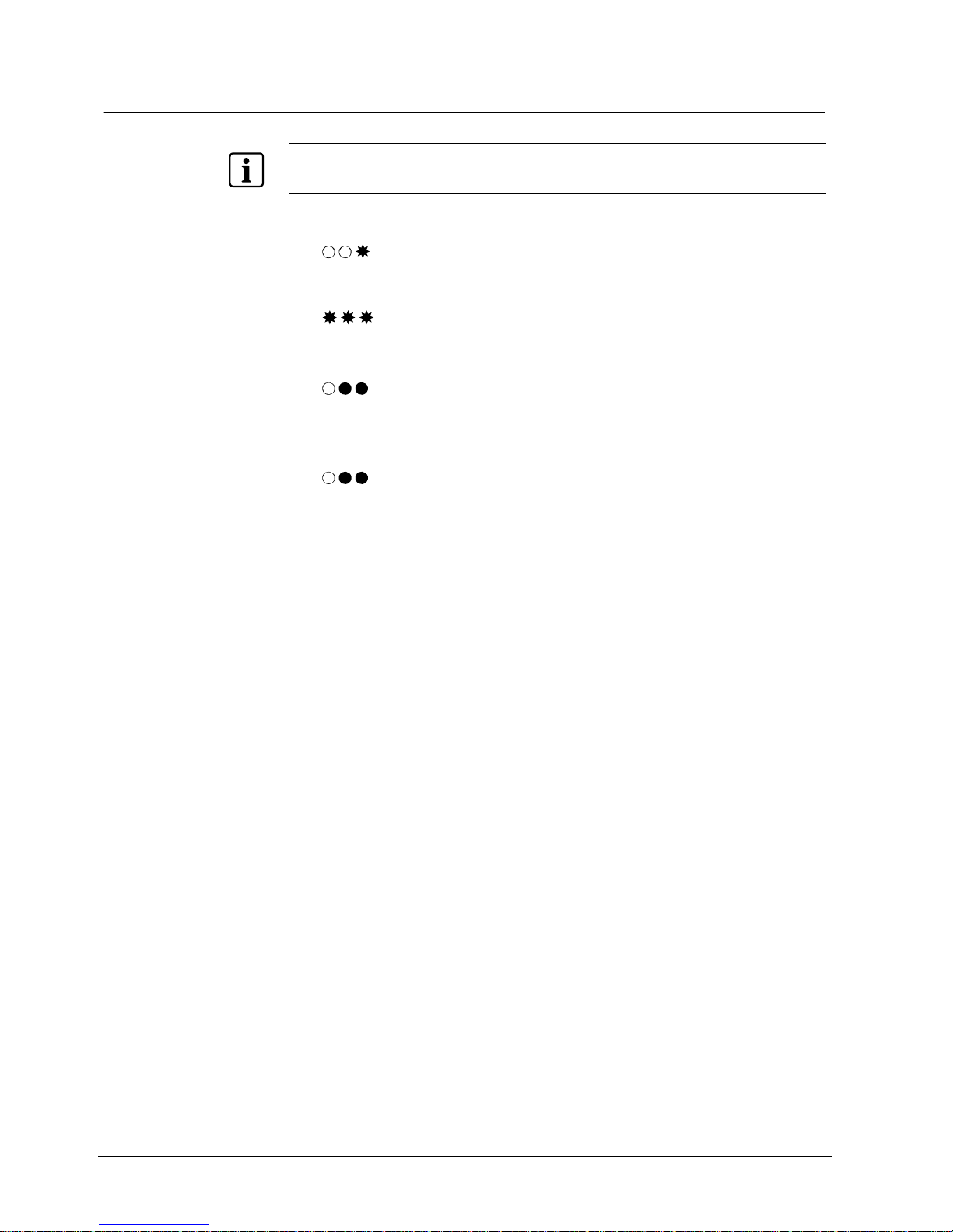
Fristående läge
58
Siemens AG
04.2010
11.1.2 Lägga till ett kort genom att ange koden
OBS!
Om du har angett ett felaktigt Axx-kommando (t.ex. i steg 3 nedan) kan du avbryta kommandot och gå
ur administratörsläget genom att trycka på A igen.
1. Tryck på B.
2. Ange den 6-siffriga administratörskoden. Se avsnitt 8 Ändra administratörs-
kod.
3. Tryck på A03.
Summern avger en signal för att bekräfta.
– eller –
Om minnet är fullt kommer summern att avge en felsignal och återgå till
administratörsläget.
4. Ange de sista åtta siffrorna på knappsatsen.
Summern avger en signal för att bekräfta.
5. Lägg till nästa kort om tillämpligt.
Page 59
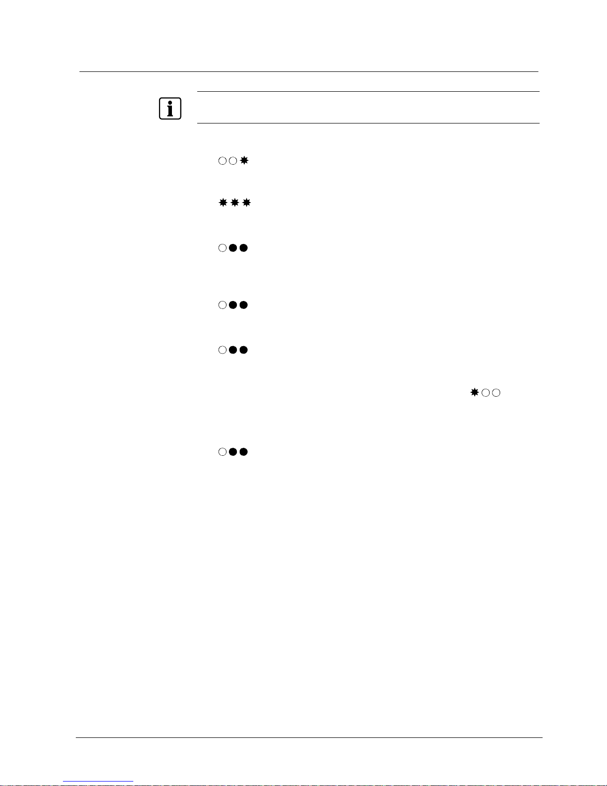
Fristående läge
59
Siemens AG
04.2010
11.1.3 Logga på en serie kort
OBS!
Om du har angett ett felaktigt Axx-kommando (t.ex. i steg 3 nedan) kan du avbryta kommandot och gå
ur administratörsläget genom att trycka på A igen.
1. Tryck på B.
2. Ange den 6-siffriga ad mi nistratörskoden. Se avsni t t 8 Än dr a administratörs-
kod.
3. Tryck på A04.
Summern avger en signal för att bekräfta.
– eller –
Om minnet är fullt kommer summern att avge en felsignal och återgå till
administratörsläget.
4. Ange kortnumret för det första kortet (sista 8 siffrorna) i serien.
Summern avger en signal för att bekräfta.
5. Ange kortnumret för det sista kortet (sista 8 siffrorna) i seri en .
Summern avger en signal för att bekräfta.
Lysdiod 1 blinkar röd under hela tiden som k ort e n l og g as på.
– eller –
Om minner är fullt eller att första numret är större än det andr a numret
kommer summern att avge en felsignal och återgå till administratörsläget
Page 60

Fristående läge
60
Siemens AG
04.2010
11.2 Annullera ett kort
11.2.1 Annullera ett kort genom avläsning
OBS!
Om du har angett ett felaktigt Axx-kommando (t.ex. i steg 3 nedan) kan du avbryta kommandot och gå
ur administratörsläget genom att trycka på A igen.
1. Tryck på B.
2. Ange den 6-siffriga administratörskoden. Se avsnitt 8 Ändra administratörs-
kod.
3. Tryck på A14.
Summern avger en signal för att bekräfta..
4. Använd kortet på RF30-EM.
Summern avger en signal för att bekräfta.
5. Annullera nä st a k or t genom att använda kortet vi d RF 3 0- EM.
11.2.2 Annullera ett kort genom att ange koden
OBS!
Om du har angett ett felaktigt Axx-kommando (t.ex. i steg 3 nedan) kan du avbryta kommandot och gå
ur administratörsläget genom att trycka på A igen.
1. Tryck på B.
2. Ange den 6-siffriga administratörskoden. Se avsnitt 8 Ändra administratörs-
kod.
3. Tryck på A16.
Summern avger en signal för att bekräfta.
4. Ange kortnumret på knappsatsen.
Summern avger en signal för att bekräfta.
5. Annullera nä st a k or t genom att ange kortnumr et på k na ppsatsen.
Page 61

Fristående läge
61
Siemens AG
04.2010
11.3 Ställa in gruppkod
11.3.1 Ange gruppkod
VARNING
När du använder gruppkoder bör du vara medveten om att den allmänna
säkerheten minskar då koderna lätt kan distribueras.
OBS!
Om du har angett ett felaktigt Axx-kommando (t.ex. i steg 3 nedan) kan du avbryta kommandot och gå
ur administratörsläget genom att trycka på A igen.
Parallellt med kortläsn ing kan fyra 4-siffriga gruppkoder ställas in. Varje gruppkod
måste tilldelas ett grupp nu mmer. (1-4)
1. Tryck på B.
2. Ange den 6-siffriga ad mi nistratörskoden. Se avsni t t 8 Än dr a administratörs-
kod.
3. Tryck på A21.
Summern avger en signal för att bekräfta.
4. Mata in ett 1-siffrigt gruppnummer (1-4).
Summern avger en signal för att bekräfta.
5. Ange önskad 4-siffrig gruppkod.
Summern avger en signal för att bekräfta.
6. För att ställa in ytterligare gruppkoder, upprepa steg 4-5.
Page 62

Fristående läge
62
Siemens AG
04.2010
11.3.2 Ändra gruppkod
1. Tryck på B.
2. Ange den 6-siffriga administratörskoden. Se avsnitt 8 Ändra administratörs-
kod.
3. Tryck på A21.
Summern avger en signal för att bekräfta.
4. Mata in med ett 1-siffrigt gruppnummer (1-4).
Summern avger en signal för att bekräfta.
5. Ange önskad 4-siffrig gruppkod.
Summern avger en signal för att bekräfta.
Den befintliga gruppkoden skrivs över.
6. För att ändra ytterligare gruppkoder, upprepa steg 4-5.
11.3.3 Ta bort gruppkod
1. Tryck på B.
2. Ange den 6-siffriga administratörskoden. Se avsnitt 8 Ändra administratörs-
kod.
3. Tryck på A21.
Summern avger en signal.
4. Mata in med ett 1-siffrigt gruppnummer (1-4).
Summern avger en signal.
5. Ange 0000.
Summern avger en signal för att bekräfta.
6. För att ta bort ytterligare gruppkoder, upprepa steg 4-5.
Page 63

Fristående läge
63
Siemens AG
04.2010
11.4 Låsa/låsa upp dörren
Låsa upp dörren
1.
Tryck på A1A.
Summern avger en signal för att bekräfta.
2. Använd ett giltigt kort på RF30-EM.
Summern avger en signal för att bekräfta.
3. Öppna dörren.
Låsa dörren
1.
Tryck på A0A.
Summern avger en signal för att bekräfta.
2. Använd ett giltigt kort på RF30-EM.
Summern avger en signal för att bekräfta.
Dörren är nu låst.
RF30-EM återgår till normal funktion.
11.5 Inaktivera/aktivera summern
Standardinställningen för summern är at t avge en signal för varje knapptr yck.
Ändra denna inställ ning om tyst användning önskas
1. Tryck på B.
2. Ange den 6-siffriga ad mi nistratörskoden. Se avsni t t 8 Än dr a administratörs-
kod.
3. Tryck på A65.
Summern avger en signal för att bekräfta.
4. För att aktivera, t ryck på 1.
- eller För att inaktivera try ck på
0.
Summern avger en signal för att bekräfta.
RF30-EM återgår till administratörsläget.
5. Tryck på B för att lämna administratör slä ge t.
Page 64
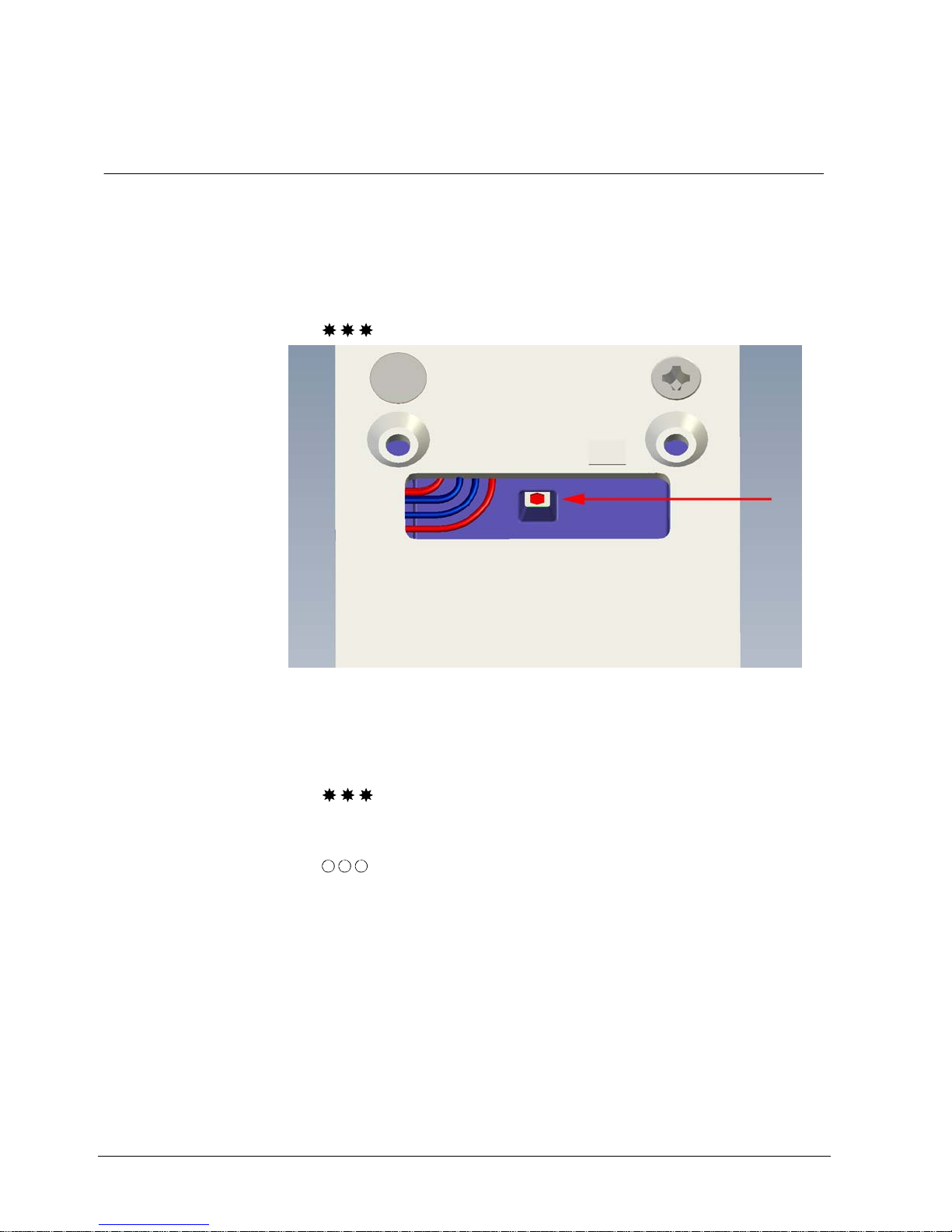
Rensa minnet
64
Siemens AG
04.2010
12 Rensa minnet
Innan en RF30-EM flyttas och tas i bruk på en annan dörr (me d nya användare),
bör du se till att inga kort/koder finns kvar. Det enklaste sättet är att rensa minnet.
1. Ta av RF30-EM från dörren.
2. Tryck och håll nere återställningskn appen på baksidan av RF 30- E M i minst 2
sekunder.
Summern avger en signal för att bekräfta.
Fig. 5 Återställningsknappen på baksidan
3. Mata in 112186.
Summern avger en signal för att bekräfta.
Efter det sista knapptrycket avges två korta och en lång signal.
4. Mata in 112186.
Summern avger en signal för att bekräfta.
Minnet är nu rensat.
Efter ungefär åtta sekunder startar RF30-EM om.
RF30-EM är i fristående läge och har föl ja nd e standardinställ ningar:
– Administratörskod: 112233
– Administratörskoden kan också användas för att låsa upp dörren.
– Alla minnespositioner är tomma.
– Summer på.
Page 65

Användning
65
Siemens AG
04.2010
13 Användning
13.1 Passage ut
RF30-EM:s mekaniska lås en he t inverkar enbart på handta ge t p å u tsidan. Dörren
kan alltid öppnas inifrån på normalt sätt.
13.2 Automatisk återställning
RF30-EM har två separata återställningssystem för återställa låset till låst läge när
en kod matats in. Låset återställs mekaniskt varje gång handtaget trycks ned för
passage. Låset återställs elektroniskt om handtaget inte trycks ned inom 4
sekunder efter att ett kort eller en kod använts.
Detta skyddar mot att obehöriga kan öppna dörren eftersom RF30-EM aldrig
lämnas i olåst läge.
13.3 Blockera åtkomst
För att förhindra att man för söker öppna dörren genom att prova olika koder i en
följd, har RF30- EM försetts med en blocker ingsfunktion som inaktiverar enheten
efter 12 felaktiga koder (tre felaktiga 4-siffriga koder i följd). Enheten förblir
blockerad tills 2 korrekta koder anges i följd.
13.4 Reservström
När batterierna börjar ta slut, blinkar den röda lysdioden på RF30-EM i 3 sekunder
innan låset öppnats. Lå se t har en reservströmförsörj ni n g so m gör att dörren
fortfarande kan öppnas 20 0 gån g er eller att en tid av två veckor har gått.
Efter att dörren har öpp na ts 200 gånger kan dörr en en da s t öppnas med
administratörskoden.
Page 66

Översiktskommandon
66
Siemens AG
04.2010
14 Översiktskommandon
Kommando 1. 2. 3. 4. 5. 6. 7.
Ändra administratörskod
Ändra administratörskod
(Existerande administratörskod känd)
Tryck på B. Ange den 6-
siffriga administratörskoden.
Tryck på A27. Ange en ny 6-
siffrig administratörskod.
Bekräfta
genom att
ange den nya
administratörskoden en
gång till.
Notera
administratörs
koden.
Ändra administratörskod
(Existerande administratörskod okänd)
Ta av RF30EM från
dörren.
Tryck på
återställningsknappen
på baksidan
av RF30-EM.
Ange en 6siffrig administratörskod.
Verifiera
genom att
ange samma
administratörskod igen.
Notera administratörskoden.
Systemläge
Aktivera systemläge Tryck på B. Ange den 6-
siffriga administratörskoden.
Ange A80. Ange ett 4-
siffrigt segment-id.
Ange en 2siffrig adress.
(01 - 32)
Ange ett 8siffrigt
installationsid.
Tryck på A.
Serviceläge
Gå till serviceläget Tryck snabbt
på B.
Håll inne B Summer
ljuder
Ange den 6siffriga administratörskoden.
Ange kommando A30,
A31, A32 eller
A34
Kontrollera signalstyrka Tryck på A30
Kontrollera länkens
tillförlitlighet
Tryck på A31
Starta om enheten Tryck på A32
Återanslut nätverk Tryck på A34
Lämna serviceläget Tryck på B.
Driftläge
Kontrollera status Tryck 0 i två
sekunder
Lysdioderna
visar status
Grön lysdiod
= OK
I övrigt se
avsnitt 7.7
Lysdiodstatus
vid anslutning
Fristående läge
Lägga till ett kort genom
avläsning
Tryck på B. Ange den 6-
siffriga administratörskoden.
Tryck på A01. Använd kortet
på RF30-EM.
Tryck på B för
att lämna
administratörsläget.
Lägga till ett kort genom
att ange koden
Tryck på B. Ange den 6-
siffriga administratörskoden.
Tryck på A03. Ange kort-
numret på
knappsatsen.
Tryck på B för
att lämna
administratörsläget.
Logga på en serie kort Tryck på B. Ange den 6-
siffriga administratörskoden.
Tryck på A04. Ange
kortnumret för
det första
kortet (sista 8
siffror) i
serien.
Ange
kortkoden för
det sista
kortet (sista 8
siffror) i
serien.
Annullera ett kort genom
avläsning
Tryck på B. Ange den 6-
siffriga administratörskoden.
Tryck på A14. Använd kortet
på RF30-EM.
Tryck på B för
att lämna
administratörl
äget.
Annullera ett kort genom
att ange koden
Tryck på B. Ange den 6-
siffriga administratörskoden.
Tryck på A16. Ange kort-
numret på
knappsatsen.
Tryck på B för
att lämna
administratörl
äget.
Page 67

Översiktskommandon
67
Siemens AG
04.2010
Kommando 1. 2. 3. 4. 5. 6. 7.
Ange gruppkod
Ändra gruppkod
Tryck på B. Ange den 6-
siffriga
administratörs
koden.
Tryck på A21. Mata in ett 1-
siffrigt gruppnummer (1-
4).
Ange önskad
4-siffrig
gruppkod.
Ta bort gruppkod Tryck på B. Ange den 6-
siffriga
administratörs
koden.
Tryck på A21. Mata in ett 1-
siffrigt gruppnummer (1-
4).
Ange 0000.
Låsa upp dörren Tryck på A1A. Använd ett
giltigt kort på
RF30-EM.
Låsa dörren Tryck på A0A. Använd ett
giltigt kort på
RF30-EM.
Inaktivera summern
Tryck på B. Ange den 6-
siffriga
administratörs
koden.
Tryck på A65. För att aktive-
ra, tryck på 0.
Tryck på B för
att lämna
administratörl
äget.
Aktivera summern
Tryck på B. Ange den 6-
siffriga
administratörs
koden.
Tryck på A65. För att inakti-
vera tryck på
1.
Tryck på B för
att lämna
administratörl
äget.
Rensa minnet
Rensa minnet Ta av RF30-
EM från
dörren.
Tryck på
återställningsknappen
på baksidan
av RF30-EM.
Mata in
112186.
Mata in
112186.
Page 68

Lösa problem
68
Siemens AG
04.2010
15 Lösa problem
Symptom Lösning
Låset öppnas inte när kortet /gruppkoden /PIN
används
Kontrollera att rätt kort /gruppkod /PIN används.
Kortet kan vara skadat.
Se till att handtaget inte är nedtryckt när koden
förs in.
Kontrollera att handtaget står horisontellt.
Kontrollera att RF30-EM har monterats exakt
vertikalt.
Kontrollera att låset inte har skruvats fast för
hårt i dörren, då kan leda till att handtaget
fastnar.
Kontrollera att den röda markeringen på
införingshylsan för handtagets kantspindel
pekar nedåt.
RF30-EM är i olåst läge Ställa in RF30-EM i låst position (om
nödvändigt). Se avsnitt 11.4 Låsa/låsa upp dörren.
RF30-EM avger ingen signal vid knapptryck Aktivera summern. Se avsnitt 7.9 Lysdiodstatus
vid batterivarning.
Summer.
Kontrollera batterierna och byt ut tomma
batterier. Se avsnitt 10.3 Byta batterier.
Batterierna är snart tomma Intensiv användning kräver frekvent byte av
batterier. Se avsnitt 10.3 Byta batterier.
Kontrollera att handtagen går tillbaka i
horisontalt läge.
Justera PIR-sensorn. Se avsnitt 10.4 Justera
PIR-sensorn.
RF30-EM tycks inte fungera Kontrollera att inte RF30-EM är i offline-läge.
Se avsnitt 7.7 Lysdiodstatus vid anslutning.
Om t.ex. en ny router anslutits kanske
kommando A34 måste utföras för att
återsansluta RF30-EM i nätverket. Se avsnitt
9.2.4 Återansluta nätverket – A34.
Röd lysdiod blinkar till och summer ljuder då kort
används
Kontrollera om kortet är ogiltigt för offline-läge.
En felsignal ljuder då kort används Tyder på mekaniskt fel (t.ex. felaktigt handtag)
Page 69

Förklarande ord l is ta
69
Siemens AG
04.2010
16 Förklarande ordlista
Förklaring
Administratörskod En kombination av alfanumeriska tecken som en administratör har
för att verifiera sig
Adress Unikt objekkt-id och/eller enhets-id inom ett system eller
sammanställda system; 1) cf. punktadress; 2) cf. användaradress
Bricka
Ett id i ett specialutförande
Gruppkod
En kombination av alfanumeriska tecken som en åtkomstgrupp har
för att verifiera sig
Installationsnyckel Binär teckensträng som används som krypteringsbas för
installatören
Kort En id-bricka i kreditkortsformat
Kortägare Person som har rätt till att använda kortet
Krypteringsnyckel Binär teckensträng som används för att kontrollera åtkomsten till
ett program eller en produkt
PIN (Personal identification
number)
En kombination av numeriska tecken som en person har för att
verifiera sig
PIR-sensor Passiv infraröd sensor
Radiolänk
Telekommunikation mellan två punkter via radiovågor
Segment-id
Numerisk teckenkombination som identifierar tillhörigheten mellan
enheterna till ett segment
Åtkomstgrupp Ett antal användare som har åtkomst på samma behörighetsnivå
Page 70

70
Siemens AG
04.2010
17 Index
A
Administratörskod, 49
Adress, 51
Antenn, 46
Användning, 65
Avstånd mellan enheter , 55
B
Batterivarning , 47
Beskrivning av utrustningen, 45
Beställningsuppgifter, 44
Byta batterier, 55
E
Enhetens adress. Se Address
F
Fristående läge, 57
Annullera ett kort, 60
Inaktivera/aktiv er a summern, 63
Låsa/låsa upp dörren, 63
Lägga till ett kort, 57
Fristående läge, 45
Förpackningens inneh åll, 44
G
Gruppkod, 61
~ ställa in, 6 1
~ ta bort, 62
~ ändra, 62
I
Installera RF30-EM i dörren, 54
K
Knappsats, 46
Kort, 57, 60
L
Lysdiodstatus, 47
Länkens tillförlitlighet, 52
Lösa problem, 68
M
Minne, 64
Montering, 45, 53
Avstånd mellan enheter, 55
Installera RF30-EM, 54
Offline-läge, 55
Testa den mekaniska funktionen, 55
Målgrupp, 41
N
Nodadress. Se Adress
O
Offline-läge, 55
P
PIR-sensor, 46
~ justera, 56
Produktbeskrivning, 41
R
Rensa minnet, 64
Reservström, 65
S
Segment-id, 51
Serviceläge, 47, 52
Signalstyrka, 52
Standarder och riktlinjer, 42
Stänga av och aktivera, 46
Summer, 48, 63
Systemläge, 45, 51
~ aktivera, 51
Säkerhet, 41
T
Tekniska data, 43
Testa den mekaniska funktionen av RF30-EM , 55
Trådlös kommunikation, 45
Ä
Ändra administratörk od, 49
Ändra administratörs ko d
Existerande administ ratörskod känd, 49
Existerande administratörskod okänd, 50
Ö
Öppna dörren, 48
Page 71

71
Siemens AG
04.2010
Page 72

Utgiven av
Siemens AG
Siemensallee 84
D-76184 Karlsruhe
www.buildingtechnologies.siemens.com/
© 2010 Copyright
Siemens AG
Data och konstruktion kan komma att ändras utan föregående meddelande.
Leverans i mån av tillgång.
Dokument nr. 81807-2
Utgåva 30.04.2010
 Loading...