

Page 1

___________________
___________________
___________________
___________________
___________________
___________________
___________________
___________________
___________________
___________________
SIMATIC Ident
RFID systems
SIMATIC RF200
System Manual
03/2019
J31069
Introduction
1
Safety notes
2
System overview
3
Planning the RF200 system
4
Readers
5
Antennas
6
Transponder
7
System integration
8
System diagnostics
9
Appendix
A
-D0227-U001-A11-7619
Page 2

Siemens AG
Division Process Indust ries and Drives
Postf ach 48 48
90026 NÜRNBERG
GERMANY
Ⓟ
Copyright © Siemens AG 2010 - 2019.
All r ights
DANGER
indicates that death or severe personal injury will result if proper precautions are not taken.
WARNING
indicates that death or severe personal injury may result if proper precautions are not taken.
CAUTION
indicates that minor personal injury can result if proper precautions are not taken.
NOTICE
indicates that property damage can result if proper precautions are not taken.
WARNING
Siemens products may only be used for the applications described in the catalog and in the relevant technical
ambient conditions must be complied with. The information in the relevant documentation must be observed.
Legal information
Warning notice system
This manual contains notices you have to observe in order to ensure your personal safety, as well as to prevent
damage to property. The notices referring to your personal safety are highlighted in the manual by a safety alert
symbol, notices referring only to property damage have no safety alert symbol. These notices shown below are
graded according to the degree of danger.
If more than one degree of danger is present, the warning notice representing the highest degree of danger will
be used. A notice warning of injury to persons with a safety alert symbol may also include a warning relating to
property damage.
Qualified Personnel
The product/system described in this documentation may be operated only by personnel qualified for the specific
task in accordance with the relevant documentation, in particular its warning notices and safety instructions.
Qualified personnel are those who, based on their training and experience, are capable of identifying risks and
avoiding potential hazards when working with these products/systems.
Proper use of Siemens products
Note the following:
documentation. If products and components from other manufacturers are used, these must be recommended
or approved by Siemens. Proper transport, storage, installation, assembly, commissioning, operation and
maintenance are required to ensure that the products operate safely and without any problems. The permissible
Trademarks
All names identified by ® are registered trademarks of Siemens AG. The remaining trademarks in this publication
may be trademarks whose use by third parties for their own purposes could violate the rights of the owner.
Disclaimer of Liability
We have reviewed the contents of this publication to ensure consistency with the hardware and software
described. Since variance cannot be precluded entirely, we cannot guarantee full consistency. However, the
information in this publication is reviewed regularly and any necessary corrections are included in subsequent
editions.
03/2019 Subject to change
reserv ed
Page 3

Table of contents
1 Introduction ............................................................................................................................13
2 Safety notes ...........................................................................................................................15
2.1 General safety instructions ................................................................................................ 15
3 System overview .....................................................................................................................19
3.1 RFID components and their function .................................................................................. 20
3.2 Overview of transponders .................................................................................................. 24
4 Planning the RF200 system ......................................................................................................27
4.1 Fundamentals of application planning ................................................................................ 27
4.1.1 Selection criteria for SIMATIC RF200 components ............................................................ 27
4.1.2 Transmission window and read/write distance ................................................................... 27
4.1.3 Width of the transmission window ...................................................................................... 30
4.1.4 Impact of secondary fields ................................................................................................. 31
4.1.5 Permissible directions of motion of the transponder ........................................................... 34
4.1.6 Operation in static and dynamic mode ............................................................................... 35
4.1.7 Dwell time of the transponder ............................................................................................ 36
4.1.8 Communication between communication module, reader and transponder ........................ 37
4.2 Field data of transponders and readers.............................................................................. 38
4.2.1 Field data .......................................................................................................................... 39
4.2.2 Minimum clearances.......................................................................................................... 56
4.3 Installation guidelines ........................................................................................................ 60
4.3.1 Overview ........................................................................................................................... 60
4.3.2 Reduction of interference due to metal............................................................................... 60
4.3.3 Effects of metal on different transponders and readers ...................................................... 62
4.3.4 Impact of metal on the transmission window ...................................................................... 63
4.3.4.1 RF210R............................................................................................................................. 64
4.3.4.2 RF220R............................................................................................................................. 67
4.3.4.3 RF240R............................................................................................................................. 69
4.3.4.4 RF250R............................................................................................................................. 72
4.3.4.5 RF260R............................................................................................................................. 81
4.3.4.6 RF280R............................................................................................................................. 83
4.3.4.7 RF285R............................................................................................................................. 86
4.3.4.8 RF290R............................................................................................................................. 91
4.3.5 Installation and connection of 2 to 6 antennas with one reader ........................................... 97
4.3.5.1 Installation options with the antenna splitter (2-4 antennas)................................................ 98
4.3.5.2 Antenna installation ..........................................................................................................101
4.4 Chemical resistance of the reader and transponders.........................................................106
4.4.1 Readers ...........................................................................................................................106
4.4.1.1 Overview of the readers and their housing materials .........................................................106
4.4.1.2 Polyester ..........................................................................................................................107
4.4.1.3 Polymethylmethacrylate (PMMA) ......................................................................................108
4.4.1.4 Polyamide 6 and Polyamide 6.6 GF30 ..............................................................................109
SIMATIC RF200
System Manual, 03/2019, J31069-D0227-U001-A11-7619
3
Page 4

Table of contents
4.4.1.5 Polyamide 12 ................................................................................................................... 110
4.4.2 Transponder ..................................................................................................................... 112
4.4.2.1 Overview of the transponders and their housing materials ................................................ 112
4.4.2.2 Epoxy resin ...................................................................................................................... 113
4.4.2.3 Polyamide 6 and Polyamide 6.6 GF30 .............................................................................. 116
4.4.2.4 Polycarbonate (PC) .......................................................................................................... 117
4.4.2.5 Polyphenylene sulfide (PPS) ............................................................................................ 118
4.4.2.6 Polyvinyl chloride (PVC) ................................................................................................... 119
4.5 Further information ........................................................................................................... 120
5 Readers ...............................................................................................................................121
5.1 SIMATIC RF210R ............................................................................................................ 122
5.1.1 Features........................................................................................................................... 122
5.1.2 RF210R ordering data ...................................................................................................... 122
5.1.3 Pin assignment RF210R with RS422 interface .................................................................. 123
5.1.4 LED operating display ...................................................................................................... 123
5.1.5 Minimum distance between RF210R readers.................................................................... 124
5.1.6 Technical specifications .................................................................................................... 125
5.1.7 Approvals ......................................................................................................................... 126
5.1.8 Dimension drawing ........................................................................................................... 127
5.2 SIMATIC RF210M ............................................................................................................ 128
5.2.1 Features........................................................................................................................... 128
5.2.2 Ordering data RF210M ..................................................................................................... 128
5.2.3 Installing the RF210M reader............................................................................................ 129
5.2.4 Pin assignment RF210M with RS-422 interface ................................................................ 130
5.2.5 LED operating display ...................................................................................................... 130
5.2.6 Technical specifications .................................................................................................... 131
5.2.7 Approvals ......................................................................................................................... 132
5.2.8 Dimension drawing ........................................................................................................... 133
5.3 SIMATIC RF220R ............................................................................................................ 134
5.3.1 Features........................................................................................................................... 134
5.3.2 RF220R ordering data ...................................................................................................... 134
5.3.3 RF220R pin assignment with RS422 interface .................................................................. 135
5.3.4 LED operating display ...................................................................................................... 135
5.3.5 Minimum distance between RF220R readers.................................................................... 136
5.3.6 Technical specifications .................................................................................................... 137
5.3.7 Approvals ......................................................................................................................... 138
5.3.8 Dimension drawing ........................................................................................................... 139
5.4 SIMATIC RF240R ............................................................................................................ 140
5.4.1 Features........................................................................................................................... 140
5.4.2 RF240R ordering data ...................................................................................................... 140
5.4.3 Pin assignment RF240R ................................................................................................... 141
5.4.4 LED operating display ...................................................................................................... 141
5.4.5 Minimum distance between several RF240R readers ....................................................... 142
5.4.6 Technical specifications .................................................................................................... 143
5.4.7 Approvals ......................................................................................................................... 145
5.4.8 Dimension drawing ........................................................................................................... 146
5.5 SIMATIC RF250R ............................................................................................................ 147
5.5.1 Features................................................................
........................................................... 147
5.5.2 Ordering data RF250R ..................................................................................................... 147
SIMATIC RF200
4 System Manual, 03/2019, J31069-D0227-U001-A11-7619
Page 5

Table of contents
5.5.3 Pin assignment RF250R ...................................................................................................148
5.5.4 LED operating display ......................................................................................................148
5.5.5 Technical specifications ....................................................................................................149
5.5.6 Approvals .........................................................................................................................151
5.5.7 Dimension drawing ...........................................................................................................152
5.6 SIMATIC RF260R ............................................................................................................153
5.6.1 Features ...........................................................................................................................153
5.6.2 Ordering data for RF260R ................................................................................................153
5.6.3 Pin assignment RF260R ...................................................................................................154
5.6.4 LED operating display ......................................................................................................154
5.6.5 Minimum distance between several RF260R ....................................................................155
5.6.6 Technical specifications ....................................................................................................156
5.6.7 Approvals .........................................................................................................................157
5.6.8 Dimension drawing ...........................................................................................................159
5.7 SIMATIC RF280R ............................................................................................................160
5.7.1 Features ...........................................................................................................................160
5.7.2 Ordering data RF280R .....................................................................................................160
5.7.3 Pin assignment RF280R ...................................................................................................161
5.7.4 LED operating display ......................................................................................................161
5.7.5 Minimum distance between RF280R readers ....................................................................162
5.7.6 Technical specifications ....................................................................................................163
5.7.7 Approvals .........................................................................................................................164
5.7.8 Dimension drawing ...........................................................................................................166
5.8 SIMATIC RF285R ............................................................................................................167
5.8.1 Characteristics .................................................................................................................167
5.8.2 Ordering data ...................................................................................................................168
5.8.3 Pin assignment .................................................................................................................169
5.8.4 LED operating display ......................................................................................................169
5.8.5 Installing the RF285R reader ............................................................................................170
5.8.5.1 Wall mounting ..................................................................................................................170
5.8.5.2 Installing on the S7-300 standard rail ................................................................................171
5.8.5.3 Installing on a standard mounting rail ................................................................................171
5.8.6 Technical specifications ....................................................................................................173
5.8.7 Approvals .........................................................................................................................174
5.8.8 Note on using the RF285R as a replacement for SLG D11 ...............................................176
5.8.9 Dimension drawing ...........................................................................................................177
5.9 SIMATIC RF290R ............................................................................................................178
5.9.1 Features ...........................................................................................................................178
5.9.2 Ordering data
...................................................................................................................179
5.9.3 Pin assignment .................................................................................................................180
5.9.4 LED operating display ......................................................................................................182
5.9.5 Installing the RF290R reader ............................................................................................183
5.9.5.1 Wall mounting ..................................................................................................................183
5.9.5.2 Installing on the S7-300 standard rail ................................................................................184
5.9.5.3 Installation on a DIN rail....................................................................................................184
5.9.6 Technical specifications ....................................................................................................186
5.9.7 Approvals .........................................................................................................................187
5.9.8 Note on the use of the RF290R as a replacement for SLG D10 / SLG D10S .....................189
5.9.9 Dimension drawing ...........................................................................................................190
SIMATIC RF200
System Manual, 03/2019, J31069-D0227-U001-A11-7619
5
Page 6

Table of contents
6 Antennas ..............................................................................................................................191
6.1 ANT 1 .............................................................................................................................. 191
6.1.1 Characteristics ................................................................................................................. 191
6.1.2 Ordering data ................................................................................................................... 191
6.1.3 Flush-mounted in metal .................................................................................................... 192
6.1.4 Minimum clearances ........................................................................................................ 192
6.1.5 Technical specifications .................................................................................................... 194
6.1.6 Dimension drawing ........................................................................................................... 195
6.2 ANT 3 .............................................................................................................................. 196
6.2.1 Features........................................................................................................................... 196
6.2.2 Ordering data ................................................................................................................... 196
6.2.3 Mounting on/in metal ........................................................................................................ 197
6.2.4 Minimum spacing ............................................................................................................. 198
6.2.5 Technical data .................................................................................................................. 199
6.2.6 Dimension drawing ........................................................................................................... 200
6.3 ANT 3S ............................................................................................................................ 201
6.3.1 Features........................................................................................................................... 201
6.3.2 Ordering data ................................................................................................................... 201
6.3.3 Mounting on/in metal ........................................................................................................ 202
6.3.4 Minimum spacing ............................................................................................................. 203
6.3.5 Technical data .................................................................................................................. 204
6.3.6 Dimension drawing ........................................................................................................... 205
6.4 ANT 8 .............................................................................................................................. 206
6.4.1 Features........................................................................................................................... 206
6.4.2 Ordering data ................................................................................................................... 206
6.4.3 Transmission window ....................................................................................................... 207
6.4.4 Flush-mounted in metal .................................................................................................... 207
6.4.5 Minimum spacing ............................................................................................................. 208
6.4.6 Technical data .................................................................................................................. 209
6.4.7 Dimension drawing ........................................................................................................... 210
6.5 ANT 12............................................................................................................................. 211
6.5.1 Features........................................................................................................................... 211
6.5.2 Ordering data ................................................................................................................... 211
6.5.3 Transmission window ....................................................................................................... 212
6.5.4 Flush-mounted in metal .................................................................................................... 212
6.5.5 Minimum spacing ............................................................................................................. 213
6.5.6 Technical data .................................................................................................................. 214
6.5.7 Dimension drawing ........................................................................................................... 215
6.6 ANT 12 (stainless steel variant) ........................................................................................ 216
6.6.1 Features........................................................................................................................... 216
6.6.2 Ordering data ................................................................................................................... 216
6.6.3 Antenna connection.......................................................................................................... 217
6.6.4 Transmission window ....................................................................................................... 218
6.6.5 Flush-mounted in metal .................................................................................................... 219
6.6.6 Minimum spacing ............................................................................................................. 219
6.6.7 Technical data .................................................................................................................. 221
6.6.8 Dimension drawing ........................................................................................................... 222
6.7 ANT 18............................................................................................................................. 223
6.7.1 Features........................................................................................................................... 223
SIMATIC RF200
6 System Manual, 03/2019, J31069-D0227-U001-A11-7619
Page 7

Table of contents
6.7.2 Ordering data ...................................................................................................................223
6.7.3 Transmission window .......................................................................................................224
6.7.4 Flush-mounted in metal ....................................................................................................224
6.7.5 Minimum spacing .............................................................................................................225
6.7.6 Technical data ..................................................................................................................226
6.7.7 Dimension drawing ...........................................................................................................227
6.8 ANT 18 (stainless steel variant) ........................................................................................228
6.8.1 Features ...........................................................................................................................228
6.8.2 Ordering data ...................................................................................................................228
6.8.3 Antenna connection ..........................................................................................................229
6.8.4 Transmission window .......................................................................................................230
6.8.5 Flush-mounted in metal ....................................................................................................230
6.8.6 Minimum spacing .............................................................................................................231
6.8.7 Technical data ..................................................................................................................232
6.8.8 Dimension drawing ...........................................................................................................234
6.9 ANT 30 .............................................................................................................................235
6.9.1 Features ...........................................................................................................................235
6.9.2 Ordering data ...................................................................................................................235
6.9.3 Transmission window .......................................................................................................236
6.9.4 Flush-mounted in metal ....................................................................................................237
6.9.5 Minimum spacing .............................................................................................................237
6.9.6 Technical data ..................................................................................................................239
6.9.7 Dimension drawing ...........................................................................................................240
6.10 ANT 30 (stainless steel variant) ........................................................................................241
6.10.1 Features ...........................................................................................................................241
6.10.2 Ordering data ...................................................................................................................241
6.10.3 Antenna connection ..........................................................................................................242
6.10.4 Transmission window .......................................................................................................243
6.10.5 Flush-mounted in metal ....................................................................................................244
6.10.6 Minimum spacing .............................................................................................................244
6.10.7 Technical data ..................................................................................................................246
6.10.8 Dimension drawing ...........................................................................................................247
6.11 ANT D1 ............................................................................................................................248
6.11.1 Characteristics .................................................................................................................248
6.11.2 Ordering data ...................................................................................................................248
6.11.3 Flush mounting on/in metal ...............................................................................................249
6.11.4 Minimum clearances.........................................................................................................249
6.11.5 Technical specifications
....................................................................................................251
6.11.6 Dimension drawing ...........................................................................................................252
6.12 ANT D5 ............................................................................................................................253
6.12.1 Features ...........................................................................................................................253
6.12.2 Ordering data ...................................................................................................................253
6.12.3 Transmission window .......................................................................................................254
6.12.4 Flush-mounted in metal ....................................................................................................255
6.12.5 Minimum spacing .............................................................................................................255
6.12.6 Technical data ..................................................................................................................257
6.12.7 Dimension drawing ...........................................................................................................258
6.13 ANT D6 ............................................................................................................................259
6.13.1 Features ...........................................................................................................................259
SIMATIC RF200
System Manual, 03/2019, J31069-D0227-U001-A11-7619
7
Page 8

Table of contents
6.13.2 Ordering data ................................................................................................................... 259
6.13.3 Transmission window ....................................................................................................... 260
6.13.4 Metal-free area ................................................................................................................. 261
6.13.5 Minimum distance ............................................................................................................ 261
6.13.6 Technical data .................................................................................................................. 262
6.13.7 Dimensional diagram ........................................................................................................ 263
6.14 ANT D10 .......................................................................................................................... 264
6.14.1 Features........................................................................................................................... 264
6.14.2 Ordering data ................................................................................................................... 264
6.14.3 Transmission window ....................................................................................................... 265
6.14.4 Metal-free area ................................................................................................................. 266
6.14.5 Minimum distance ............................................................................................................ 267
6.14.6 Technical data .................................................................................................................. 267
6.14.7 Dimensional diagram ........................................................................................................ 269
7 Transponder .........................................................................................................................271
7.1 Memory configuration of ISO the transponders ................................................................. 271
7.2 MDS D100 ....................................................................................................................... 272
7.2.1 Characteristics ................................................................................................................. 272
7.2.2 Ordering data ................................................................................................................... 273
7.2.3 Metal-free area ................................................................................................................. 273
7.2.4 Technical data .................................................................................................................. 275
7.2.5 Dimension drawing ........................................................................................................... 276
7.3 MDS D117 ....................................................................................................................... 277
7.3.1 Features........................................................................................................................... 277
7.3.2 Ordering data ................................................................................................................... 277
7.3.3 Mounting in metal ............................................................................................................. 277
7.3.4 Technical specifications .................................................................................................... 278
7.3.5 Dimension drawing ........................................................................................................... 279
7.4 MDS D124 ....................................................................................................................... 280
7.4.1 Characteristics ................................................................................................................. 280
7.4.2 Ordering data ................................................................................................................... 280
7.4.3 Mounting on metal ............................................................................................................ 281
7.4.4 Technical specifications .................................................................................................... 282
7.4.5 Using the MDS D124 in hazardous areas ......................................................................... 284
7.4.6 EC declaration of conformity according to directive 2014/34/EU MDS D124 ...................... 286
7.4.7 Dimension drawing ........................................................................................................... 286
7.5 MDS D126 ....................................................................................................................... 287
7.5.1 Characteristics ................................................................................................................. 287
7.5.2 Ordering data ................................................................................................................... 287
7.5.3 Mounting on metal ............................................................................................................ 288
7.5.4 Technical specifications .................................................................................................... 289
7.5.5 Dimension drawing ........................................................................................................... 290
7.6 MDS D127 ....................................................................................................................... 291
7.6.1 Features........................................................................................................................... 291
7.6.2 Ordering data ................................................................................................................... 291
7.6.3 Mounting in metal ............................................................................................................. 292
7.6.4 Technical specifications .................................................................................................... 293
7.6.5 Dimension drawing ........................................................................................................... 294
SIMATIC RF200
8 System Manual, 03/2019, J31069-D0227-U001-A11-7619
Page 9

Table of contents
7.7 MDS D139 .......................................................................................................................295
7.7.1 Characteristics .................................................................................................................295
7.7.2 Ordering data ...................................................................................................................295
7.7.3 Metal-free area .................................................................................................................296
7.7.4 Mounting in metal .............................................................................................................297
7.7.5 Cleaning the transponder .................................................................................................297
7.7.6 Technical specifications ....................................................................................................298
7.7.7 Using the MDS D139 in hazardous areas .........................................................................300
7.7.8 Dimension drawings .........................................................................................................302
7.8 MDS D160 .......................................................................................................................303
7.8.1 Characteristics .................................................................................................................303
7.8.2 Ordering data ...................................................................................................................303
7.8.3 Mounting on metal ............................................................................................................304
7.8.4 Technical specifications ....................................................................................................305
7.8.5 Dimension drawings .........................................................................................................307
7.9 MDS D165 .......................................................................................................................308
7.9.1 Features ...........................................................................................................................308
7.9.2 Ordering data ...................................................................................................................308
7.9.3 Technical data ..................................................................................................................309
7.9.4 Dimension drawing ...........................................................................................................310
7.10 MDS D200 .......................................................................................................................311
7.10.1 Features ...........................................................................................................................311
7.10.2 Ordering data ...................................................................................................................311
7.10.3 Mounting on metal ............................................................................................................312
7.10.4 Technical data ..................................................................................................................314
7.10.5 Dimension drawing ...........................................................................................................315
7.11 MDS D261 .......................................................................................................................316
7.11.1 Features ...........................................................................................................................316
7.11.2 Ordering data ...................................................................................................................316
7.11.3 Technical data ..................................................................................................................317
7.11.4 Dimension drawing ...........................................................................................................318
7.12 MDS D324 .......................................................................................................................319
7.12.1 Characteristics .................................................................................................................319
7.12.2 Ordering data ...................................................................................................................319
7.12.3 Mounting on metal ............................................................................................................320
7.12.4 Technical specifications ....................................................................................................321
7.12.5 Dimension drawing ...........................................................................................................322
7.13 MDS D339 ................................................................................................
.......................323
7.13.1 Characteristics .................................................................................................................323
7.13.2 Ordering data ...................................................................................................................323
7.13.3 Mounting on metal ............................................................................................................324
7.13.4 Mounting in metal .............................................................................................................325
7.13.5 Cleaning the transponder .................................................................................................325
7.13.6 Technical specifications ....................................................................................................326
7.13.7 Using the MDS D339 in hazardous areas .........................................................................328
7.13.8 Dimensional drawing ........................................................................................................330
7.14 MDS D400 .......................................................................................................................331
7.14.1 Features ...........................................................................................................................331
7.14.2 Ordering data ...................................................................................................................331
SIMATIC RF200
System Manual, 03/2019, J31069-D0227-U001-A11-7619
9
Page 10

Table of contents
7.14.3 Mounting on metal ............................................................................................................ 332
7.14.4 Technical specifications .................................................................................................... 334
7.14.5 Dimension drawing ........................................................................................................... 335
7.15 MDS D421 ....................................................................................................................... 336
7.15.1 Characteristics ................................................................................................................. 336
7.15.2 Ordering data ................................................................................................................... 336
7.15.3 Mounting on metal ............................................................................................................ 337
7.15.4 Technical specifications .................................................................................................... 339
7.15.5 Dimension drawing ........................................................................................................... 341
7.16 MDS D422 ....................................................................................................................... 342
7.16.1 Characteristics ................................................................................................................. 342
7.16.2 Ordering data ................................................................................................................... 342
7.16.3 Mounting in metal ............................................................................................................. 342
7.16.4 Technical specifications .................................................................................................... 343
7.16.5 Dimension drawing ........................................................................................................... 344
7.17 MDS D423 ....................................................................................................................... 345
7.17.1 Characteristics ................................................................................................................. 345
7.17.2 Ordering data ................................................................................................................... 345
7.17.3 Mounting on metal ............................................................................................................ 346
7.17.4 Technical specifications .................................................................................................... 347
7.17.5 Dimensional drawing ........................................................................................................ 349
7.18 MDS D424 ....................................................................................................................... 350
7.18.1 Characteristics ................................................................................................................. 350
7.18.2 Ordering data ................................................................................................................... 350
7.18.3 Mounting on metal ............................................................................................................ 351
7.18.4 Technical specifications .................................................................................................... 352
7.18.5 Dimension drawing ........................................................................................................... 353
7.19 MDS D425 ....................................................................................................................... 354
7.19.1 Characteristics ................................................................................................................. 354
7.19.2 Ordering data ................................................................................................................... 354
7.19.3 Application example ......................................................................................................... 355
7.19.4 Technical specifications .................................................................................................... 355
7.19.5 Dimension drawing ........................................................................................................... 357
7.20 MDS D426 ....................................................................................................................... 358
7.20.1 Characteristics
................................................................................................................. 358
7.20.2 Mounting on metal ............................................................................................................ 358
7.20.3 Ordering data ................................................................................................................... 359
7.20.4 Technical specifications .................................................................................................... 360
7.20.5 Dimension drawing ........................................................................................................... 361
7.21 MDS D428 ....................................................................................................................... 362
7.21.1 Characteristics ................................................................................................................. 362
7.21.2 Ordering data ................................................................................................................... 362
7.21.3 Application example ......................................................................................................... 363
7.21.4 Technical specifications .................................................................................................... 363
7.21.5 Dimension drawing ........................................................................................................... 365
7.22 MDS D460 ....................................................................................................................... 366
7.22.1 Characteristics ................................................................................................................. 366
7.22.2 Ordering data ................................................................................................................... 366
SIMATIC RF200
10 System Manual, 03/2019, J31069-D0227-U001-A11-7619
Page 11

Table of contents
7.22.3 Mounting on metal ............................................................................................................367
7.22.4 Technical specifications ....................................................................................................368
7.22.5 Dimension drawings .........................................................................................................369
7.23 MDS D521 .......................................................................................................................370
7.23.1 Characteristics .................................................................................................................370
7.23.2 Ordering data ...................................................................................................................370
7.23.3 Mounting on metal ............................................................................................................370
7.23.4 Technical specifications ....................................................................................................373
7.23.5 Dimension drawing ...........................................................................................................374
7.24 MDS D522 .......................................................................................................................375
7.24.1 Characteristics .................................................................................................................375
7.24.2 Ordering data ...................................................................................................................375
7.24.3 Mounting in metal .............................................................................................................375
7.24.4 Technical specifications ....................................................................................................376
7.24.5 Dimension drawing ...........................................................................................................377
7.25 MDS D522 special variant ................................................................................................378
7.25.1 Characteristics .................................................................................................................378
7.25.2 Ordering data ...................................................................................................................378
7.25.3 Mounting in metal .............................................................................................................379
7.25.4 Installation instructions .....................................................................................................379
7.25.5 Technical specifications ....................................................................................................381
7.25.6 Dimensional drawing ........................................................................................................383
7.26 MDS D524 .......................................................................................................................384
7.26.1 Characteristics .................................................................................................................384
7.26.2 Ordering data ...................................................................................................................384
7.26.3 Mounting on metal ............................................................................................................385
7.26.4 Technical specifications ....................................................................................................386
7.26.5 Dimension drawing ...........................................................................................................387
7.27 MDS D525 .......................................................................................................................388
7.27.1 Characteristics .................................................................................................................388
7.27.2 Ordering data ...................................................................................................................388
7.27.3 Application example .........................................................................................................389
7.27.4 Technical specifications ....................................................................................................389
7.27.5 Dimension drawing ...........................................................................................................391
7.28 MDS D526 .......................................................................................................................392
7.28.1 Characteristics .................................................................................................................392
7.28.2 Ordering data ...................................................................................................................392
7.28.3 Mounting on metal ................................................................................................
............393
7.28.4 Technical specifications ....................................................................................................394
7.28.5 Dimension drawing ...........................................................................................................395
7.29 MDS D528 .......................................................................................................................396
7.29.1 Characteristics .................................................................................................................396
7.29.2 Ordering data ...................................................................................................................396
7.29.3 Application example .........................................................................................................397
7.29.4 Technical specifications ....................................................................................................397
7.29.5 Dimension drawing ...........................................................................................................399
7.30 MDS D560 .......................................................................................................................400
7.30.1 Characteristics .................................................................................................................400
SIMATIC RF200
System Manual, 03/2019, J31069-D0227-U001-A11-7619
11
Page 12

Table of contents
7.30.2 Ordering data ................................................................................................................... 400
7.30.3 Mounting on metal ............................................................................................................ 401
7.30.4 Technical specifications .................................................................................................... 402
7.30.5 Dimension drawings ......................................................................................................... 403
8 System integration .................................................................................................................405
9 System diagnostics ................................................................................................................409
9.1 Error codes of the RF200 readers..................................................................................... 409
9.2 Diagnostics functions - STEP 7 ........................................................................................ 411
9.2.1 Reader diagnostics with "Reader Status" (SLG Status) ..................................................... 411
9.2.2 Transponder diagnostics with "Tag Status" (MDS Status) ................................................. 413
A Appendix ..............................................................................................................................415
A.1 Certificates & approvals .................................................................................................... 415
A.2 Accessories...................................................................................................................... 418
A.2.1 Antenna splitter ................................................................................................................ 418
A.2.2 Wide-range power supply unit for SIMATIC RF systems ................................................... 420
A.2.2.1 Features........................................................................................................................... 420
A.2.2.2 Scope of supply................................................................................................................ 420
A.2.2.3 Ordering data ................................................................................................................... 421
A.2.2.4 Safety Information ............................................................................................................ 422
A.2.2.5 Mounting & connecting ..................................................................................................... 423
A.2.2.6 Pin assignment of DC outputs and mains connection ........................................................ 427
A.2.2.7 Technical specifications .................................................................................................... 427
A.2.2.8 Dimension drawing ........................................................................................................... 430
A.2.2.9 Certificates and approvals ................................................................................................ 431
A.2.3 Transponder holders ........................................................................................................ 433
A.3 Connecting cable ............................................................................................................. 440
A.3.1 RF2xxR reader (RS-422) with ASM 456 / RF160C / RF170C / RF180C / RF18xC /
RF182C ........................................................................................................................... 440
A.3.2 Reader RF2xxR (RS-422) with ASM 475 .......................................................................... 442
A.3.3 Reader RF2xxR (RS-422) with RF120C ........................................................................... 443
A.3.4 RF240R/RF260R/RF285R/RF290R (RS232) readers with PC .......................................... 444
A.3.5 RF285R/RF290R readers ................................................................................................. 445
A.4 Ordering data ................................................................................................................... 446
A.5 Service & Support ............................................................................................................ 458
SIMATIC RF200
12 System Manual, 03/2019, J31069-D0227-U001-A11-7619
Page 13

1
SIMATIC RF200 is a compact RFID system in the SIMATIC RFID product family. The
product range comprises cost-efficient RF readers that are ideal for use in small assembly
lines or in intralogistics. SIMATIC RF200 RFID readers only support the RFID standard ISO
15693 and are therefore ideal for operation with the extensive range of ISO 15693
transponders.
The readers of the RF200 product family are available with the following interfaces:
● RS-422 for connecting to the communications modules
● RS-232 with a simple ASCII protocol for connection to PCs and third-party controllers
● IO-Link for connection to IO Link masters from Siemens and third-party controllers
Readers with an internal antenna have a particularly compact design
(RF210R/RF220R/RF240R/RF260R). RF250R, RF285R and RF290R are designed for
operation with external antennas either to achieve longer distances or larger field sizes
(RF285R and RF290R with ANT D1/D5/D6/D10) or to allow installation where there is very
little space (RF250R with ANT 3/3S/8/12/18/30).
Scope of validity of this document
This documentation is valid for all variants of the SIMATIC RF200 system and describes the
devices shipped as of March 2019.
Additional information
You will find additional information on the devices listed in this manual and their configuration
and parameter assignment in the following manuals:
● Function manual "Ident profile and Ident blocks, standard function for Ident systems"
● Function manual "FB 45 for MOBY U, MOBY D, RF200, RF300"
● Operating Instructions "SIMATIC RF200 IO-Link"
● System manual "MOBY D"
● Operating Instructions "Mobile reader RF350M"
● Product information "SIMATIC RF200 command set"
You will find the latest versions of these manuals on the pages of the Siemens Industry
Online Support (https://support.industry.siemens.com/cs/ww/en/ps/14971/man).
Registered trademarks
SIMATIC ®, SIMATIC RF ®, MOBY ®, RF MANAGER ® and SIMATIC Sensors ® are registered
trademarks of Siemens AG.
SIMATIC RF200
System Manual, 03/2019, J31069-D0227-U001-A11-7619
13
Page 14

Introduction
Output
Note
03/2011
First edition
...
...
Reader
Write/read device (SLG)
Transponder, tag
Data carrier, mobile data storage, (MDS)
Communications module (CM)
Interface module (ASM)
Recycling and disposal
The products are low in harmful substances, can be recycled and meet the requirements of
the Directive 2012/19/EU for disposal of waste electrical and electronic equipment (WEEE).
Do not dispose of the products at public disposal sites.
For environmentally compliant recycling and disposal of your electronic waste, please
contact a company certified for the disposal of electronic waste or your Siemens
representative.
Note the different country-specific regulations.
History
The following issues of the SIMATIC RF200 system manual have been published:
07/2015 Expansion of the documentation by the following:
• ANT 3 antennas
• MDS D5xx transponder
• Mobile reader RF210R
07/2017 Expansion of the documentation by the following:
• Reader RF280R
• Mobile Reader RF350M
xx/2019 Expansion of the documentation by the following:
• Reader RF285R
• Antenna ANT 3S, ANT D1
• Antennas ANT 12, ANT 18, ANT 30 (stainless steel variants)
• MDS D525 / MDS D560 transponders
Abbreviations and naming conventions
The following terms/abbreviations are used synonymously in this document:
SIMATIC RF200
14 System Manual, 03/2019, J31069-D0227-U001-A11-7619
Page 15

2
WARNING
Opening the device
NOTICE
Alterations not permitted
NOTICE
Switch/fuse to disconnect the reader from the power supply
fuse. The function of the switch or fuse must be clearly recognizable.
CAUTION
Danger of burns
2.1 General safety instructions
SIMATIC RFID products comply with the salient safety specifications acc. to IEC, VDE, EN,
UL and CSA. If you have questions about the permissibility of the installation in the planned
environment, please contact your service representative.
Do not open the device when when the power supply is on. Unauthorized opening of and
improper repairs to the device may result in substantial damage to equipment or risk of
personal injury to the user.
Alterations to the devices are not permitted.
Failure to observe this requirement shall constitute a revocation of the radio equipment
approval, CE approval and manufacturer's warranty.
Installation instructions
Make sure that the readers can be disconnected from the power supply with a switch or a
Operating temperature
Note that some outer components of the reader are made of metal. Depending on the
environmental conditions temperatures can occur on the device that are higher than the
maximum permitted operating temperature.
SIMATIC RF200
System Manual, 03/2019, J31069-D0227-U001-A11-7619
15
Page 16

Safety notes
WARNING
Repairs only by authorized qualified personnel
Repairs may only be carried out by authorized qualified personnel. Unauthorized opening of
personal injury to the user.
NOTICE
Warranty conditions
2.1 General safety instructions
Repairs
and improper repairs to the device may result in substantial damage to equipment or risk of
System expansions
Only install system expansions intended for this system. If you install other expansions, you
may damage the system or violate the safety requirements and regulations for radio
frequency interference suppression. Contact Technical Support or your local sales
department to find out which system expansions are suitable for installation.
If you cause system defects by installing or exchanging system expansion devices, the
warranty becomes void.
SIMATIC RF200
16 System Manual, 03/2019, J31069-D0227-U001-A11-7619
Page 17

Safety notes
CAUTION
Safety distance between reader/antenna and persons
Note
Safety distance with pacemakers
An increased safety distance between reader/antenna and persons with pacemakers is not
necessary.
2.1 General safety instructions
Safety distances
Note that for permanent exposure, the following safety distances must be adhered to:
• RF210R: ≥ 25 mm
• RF220R: ≥ 50 mm
• RF240R: ≥ 100 mm
• RF250R + ANT 1: ≥ 120 mm
• RF250R + ANT 3 or ANT 30: ≥ 50 mm
• RF250R + ANT 3S or ANT 12: ≥ 25 mm
• RF250R + ANT 18: ≥ 40 mm
• RF260R: ≥ 120 mm
• RF280R: ≥ 250 mm
• RF285R + ANT D1: ≥ 250 mm
• RF285R + ANT D5: ≥ 400 mm
• RF285R + ANT D6: ≥ 450 mm
• RF290R + ANT D1: ≥ 250 mm (max. 2 W permissible)
• RF290R + ANT D5: ≥ 450 mm
• RF290R + ANT D6: ≥ 600 mm
• RF290R + ANT D10: ≥ 600 mm
SIMATIC RF200
System Manual, 03/2019, J31069-D0227-U001-A11-7619
17
Page 18

Safety notes
2.1 General safety instructions
Security information
Siemens provides products and solutions with industrial security functions that support the
secure operation of plants, systems, machines and networks.
In order to protect plants, systems, machines and networks against cyber threats, it is
necessary to implement – and continuously maintain – a holistic, state-of-the-art industrial
security concept. Siemens’ products and solutions constitute one element of such a concept.
Customers are responsible for preventing unauthorized access to their plants, systems,
machines and networks. Such systems, machines and components should only be
connected to an enterprise network or the internet if and to the extent such a connection is
necessary and only when appropriate security measures (e.g. firewalls and/or network
segmentation) are in place.
For additional information on industrial security measures that may be implemented, please
visit
Link: (http://www.siemens.com/industrialsecurity)
Siemens’ products and solutions undergo continuous development to make them more
secure. Siemens strongly recommends that product updates are applied as soon as they are
available and that the latest product versions are used. Use of product versions that are no
longer supported, and failure to apply the latest updates may increase customers’ exposure
to cyber threats.
To stay informed about product updates, subscribe to the Siemens Industrial Security RSS
Feed under
Link: (http://www.siemens.com/industrialsecurity)
SIMATIC RF200
18 System Manual, 03/2019, J31069-D0227-U001-A11-7619
Page 19

3
SIMATIC RF200 is an inductive identification system that is compatible with the ISO 15693
standard and was specially designed for use in industrial production for the control and
optimization of material flows.
In contrast to SIMATIC RF300, SIMATIC RF200 is intended for RFID applications where
performance requirements are not very high, for example with regard to data volume,
transfer rate or diagnostics options. SIMATIC RF200 is characterized by particularly
favorable prices.
SIMATIC RF200
System Manual, 03/2019, J31069-D0227-U001-A11-7619
19
Page 20
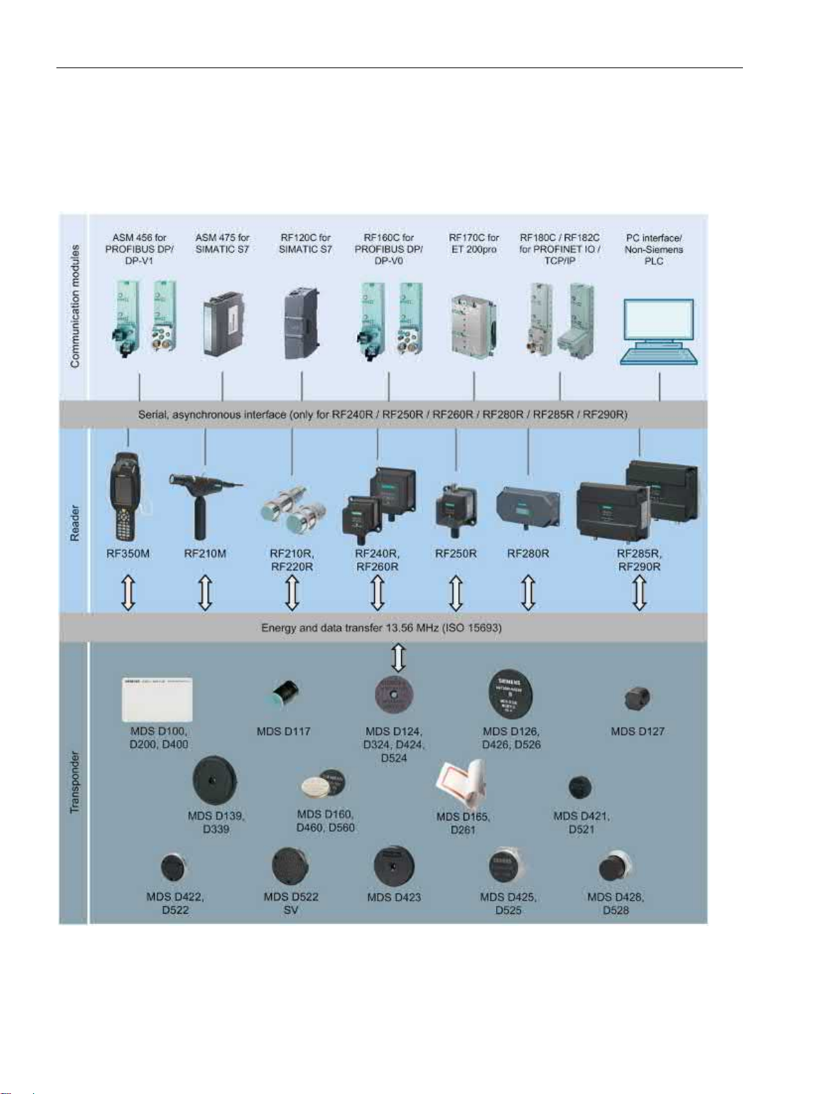
System overview
3.1 RFID components and their function
3.1 RFID components and their function
RF200 system components
Figure 3-1 RF200 system overview
SIMATIC RF200
20 System Manual, 03/2019, J31069-D0227-U001-A11-7619
Page 21

System overview
Transponder
RF210R/
RF210M
RF220R
RF240R
RF260R
RF280R
RF350M
MDS D100
-- ○ ✓ ✓ ✓
✓
MDS D117 ○ --
--
--
--
✓
MDS D124 ✓ ✓ ✓ ✓ ✓ ✓
MDS D126
-- ✓ ✓ ✓ ✓
✓
MDS D127 ✓ --
--
--
--
✓
MDS D139 1)
-- ○ ○ ✓ ✓
✓
MDS D160 2)
✓ ✓ ✓ ✓ ✓
✓
MDS D165
-- ○ ✓ ✓ ✓
✓
MDS D200
-- ○ ✓ ✓ ✓
✓
MDS D261
-- ○ ✓ ✓ ✓
✓
MDS D324 ✓ ✓ ✓ ✓ ✓ ✓
MDS D339
-- ○ ○ ✓ ✓
✓
MDS D400
--
-- ✓ ✓ ✓ ✓
MDS D421 ✓ ○
--
--
--
✓
MDS D422 ✓ ✓ ✓ --
--
✓
MDS D423 ✓ ✓ ✓ ✓ ✓ ✓
MDS D424 ✓ ✓ ✓ ✓ ✓ ✓
MDS D425 ✓ ✓ ✓ -- ✓ ✓
MDS D426
-- ✓ ✓ ✓ ✓
✓
MDS D428 ✓ ✓ ✓ ✓ ✓ ✓
MDS D460 ✓ ✓ ✓ ✓ ✓ ✓
MDS D521 ✓ ○
--
--
--
✓
MDS D522 3)
✓ ✓ ✓
--
--
✓
MDS D524 ✓ ✓ ✓ ✓ ✓ ✓
MDS D525 ✓ ✓ ✓ -- ✓ --
MDS D526
-- ✓ ✓ ✓ ✓
✓
MDS D528 ✓ ✓ ✓ ✓ ✓ ✓
MDS D560 ✓ ✓ ✓ ✓ ✓ ✓
1)
2)
3)
4)
5)
6)
Only in conjunction with RF350M for external antennas (6GT2803-1BA10)
✓
Combination possible
--
Combination not possible
○
Combination possible, but not recommended
3.1 RFID components and their function
Table 3- 1 Reader-transponder combination options - Part 1
6)
6)
6)
6)
only with the article number 6GT2600-0AA10
only with the article number 6GT2600-0AB10
The transponder MDS D522 special variant has the same compatibility as the transponder MDS D522.
in conjunction with ANT D5, D6 or D10
combination recommended only in conjunction with ANT D5.
SIMATIC RF200
System Manual, 03/2019, J31069-D0227-U001-A11-7619
6)
6)
21
Page 22

System overview
Transponder
RF250R with
ANT 1
ANT 3
ANT 3S
ANT 8
ANT 12
ANT 18
ANT 30
MDS D100
✓
--
--
--
--
--
○
MDS D117
--
-- ✓ ✓ ✓ --
--
MDS D124
✓ ✓ --
--
-- ✓ ✓
MDS D126
✓ ✓ --
--
--
--
✓
MDS D127
--
-- ✓ ✓ ✓ --
--
MDS D139
✓
--
--
--
--
--
○
MDS D160
✓ ✓ --
-- ✓ ✓
✓
MDS D165
✓
--
--
--
--
--
○
MDS D200
✓
--
--
--
--
--
○
MDS D261
✓
--
--
--
--
--
○
MDS D324
✓ ✓ --
-- ○ ✓
✓
MDS D339
✓
--
--
--
--
--
○
MDS D400
✓
--
--
--
--
--
○
MDS D421
--
-- ✓ ✓ ✓ ✓
--
MDS D422
-- ✓ --
-- ✓ ✓
✓
MDS D423
✓ ✓ --
--
-- ✓ ✓
MDS D424
✓ ✓ --
--
-- ✓ ✓
MDS D425
✓ ✓ --
-- ✓ ✓
✓
MDS D426
✓ ✓ --
-- ✓ ✓
✓
MDS D428
✓ ✓ --
-- ✓ ✓
✓
MDS D460
✓ ✓ --
-- ✓ ✓
✓
MDS D521
--
-- ✓ ✓ ✓ ✓
--
MDS D522
-- ✓ --
-- ✓ ✓
✓
MDS D524
✓ ✓ -- ○ ○ ✓ ✓
MDS D525
✓ ✓ --
-- ✓ ✓
○
MDS D526
✓ ✓ --
--
--
--
✓
MDS D528
✓ ✓ --
-- ✓ ✓
✓
MDS D560
✓ ✓ --
-- ✓ ✓
✓
✓
Combination possible
--
Combination not possible
○
Combination possible, but not recommended
3.1 RFID components and their function
Table 3- 2 Reader-transponder combination options - Part 2
SIMATIC RF200
22 System Manual, 03/2019, J31069-D0227-U001-A11-7619
Page 23

System overview
Transponder
RF285R with
RF290R with
ANT D1
ANT D5
ANT D6
ANT D1
ANT D5
ANT D6
ANT D10
MDS D100
✓ ✓ ✓ ✓ ✓ ✓ ✓
MDS D117
--
--
--
--
--
--
--
MDS D124
✓ ✓ ✓ ✓ ✓ ✓ ✓
MDS D126
✓ ✓ ✓ ✓ ✓ ✓ ✓
MDS D127
--
--
--
--
--
--
--
MDS D139
✓ ✓ ✓ ✓ ✓ ✓ ✓
MDS D160
✓ ✓ ○ ✓ ✓ ○ ○
MDS D165
✓ ✓ ✓ ✓ ✓ ✓ ✓
MDS D200
✓ ✓ ✓ ✓ ✓ ✓ ✓
MDS D261
✓ ✓ ✓ ✓ ✓ ✓ ✓
MDS D324
✓ ✓ ✓ ✓ ✓ ✓ ✓
MDS D339
✓ ✓ ✓ ✓ ✓ ✓ ✓
MDS D400
✓ ✓ ✓ ✓ ✓ ✓ ✓
MDS D421
--
--
--
--
--
--
--
MDS D422
--
--
--
--
--
--
--
MDS D423
✓
--
-- ✓ --
--
--
MDS D424
✓ ✓ ✓ ✓ ✓ ✓ ✓
MDS D425
✓
--
-- ✓ --
--
--
MDS D426
✓ ✓ ✓ ✓ ✓ ✓ ✓
MDS D428
✓
--
-- ✓ --
--
--
MDS D460
✓ ✓ ○ ✓ ✓ ○ ○
MDS D521
--
--
--
--
--
--
--
MDS D522
○
--
-- ○ --
--
--
MDS D524
✓ ✓ ✓ ✓ ✓ ✓ ✓
MDS D525
✓
--
-- ✓ --
--
--
MDS D526
✓ ✓ ✓ ✓ ✓ ✓ ✓
MDS D528
✓
--
-- ✓ --
--
--
MDS D560
✓ ✓ ○ ✓ ✓ ○ ○
✓
Combination possible
--
Combination not possible
Combination possible, but not recommended
3.1 RFID components and their function
Table 3- 3 Reader-transponder combination options - Part 3
○
SIMATIC RF200
System Manual, 03/2019, J31069-D0227-U001-A11-7619
23
Page 24

System overview
Transponder
Area of application
ranges are achieved in combination with the SIMATIC RF260R reader.
tool identification.
MDS D124
Application areas in factory automation (e.g. small paintshops to 180°C).
logistics; can also be deployed in harsh conditions.
identification.
and distribution logistics, right up to product identification
and distribution logistics, right up to product identification.
MDS D324
Production and distribution logistics as well as in assembly and production lines
For typical areas of application, see "MDS D139".
3.2 Overview of transponders
3.2 Overview of transponders
Overview of typical areas of application of ISO transponders for RF200
MDS D100 From simple identification such as electronic barcode replacement or supplementation, through ware-
house and distribution logistics, right up to product identification. With this transponder, the maximum
MDS D117 Very compact data carrier that can be cemented into objects where precise positioning is necessary. e.g.
MDS D126 Compact and rugged ISO transponder; suitable for identification of transport units in production-related
MDS D127 Very compact data carrier that can be screwed into areas where precise positioning is necessary. e.g. tool
MDS D139 1) Applications in production automation with high temperature demands (up to +220 °C).
Typical application areas:
• Paintshops and their preparatory treatments
• Primer coat, electrolytic dip area, cataphoresis with the associated drying furnaces
• Top coat area with drying furnaces
• Washing areas at temperatures > 85 °C
• Other applications with higher temperatures
MDS D160 2) Typical applications are, for example:
• Rented work clothing
• Hotel laundry
• Surgical textiles
• Hospital clothing
• Dirt collection mats
• Clothing for nursing homes/hostels
• Assembly lines with very small workpiece holders
MDS D165 Smart label (self-adhesive label)
From simple identification such as electronic barcode replacement/supplementation, through warehouse
MDS D200 From simple identification such as electronic barcode replacement/supplementation, through warehouse
and distribution logistics, right up to product identification.
MDS D261 Smart label (self-adhesive label)
The design of the transponder (self-adhesive label) permits a variety of designs in order to ensure optimum dimensioning for the widest variety of applications.
From simple identification such as electronic barcode replacement/supplementation, through warehouse
MDS D339 Applications in production automation with high temperature demands (up to +220 °C).
SIMATIC RF200
24 System Manual, 03/2019, J31069-D0227-U001-A11-7619
Page 25

System overview
Transponder
Area of application
tion logistics right through to product identification.
workpiece holders
MDS D422
Identification of metallic workpiece holders, workpieces or containers
MDS D423
Identification of metallic workpiece holders, workpieces or containers, production automation
MDS D424
Production and distribution logistics as well as in assembly and production lines
and workpiece holders
logistics; can also be deployed in harsh conditions
Use in assembly and production lines in the powertrain sector
MDS D460
Assembly lines with very small workpiece holders
carriers and exact positioning are required, e.g. tool identification, workpiece holders.
MDS D522
Identification of metallic workpiece holders, workpieces or containers
ants
MDS D524
Production and distribution logistics as well as in assembly and production lines
logistics; can also be deployed in harsh environmental conditions
Use in assembly and production lines in the powertrain sector
MDS D560
Assembly lines with very small workpiece holders
1)
2)
Only with the MLFB 6GT2600-0AB10
Transponder
Memory size
MDS D1xx
112 bytes of EEPROM
MDS D2xx
256 bytes of EEPROM
MDS D3xx
992 bytes of EEPROM
MDS D4xx
2000 bytes FRAM
MDS D5xx
8192 bytes FRAM
3.2 Overview of transponders
MDS D400 Simple identification such as electronic barcode replacement/supplements, from warehouse and distribu-
MDS D421 The MDS D421 is designed for tool coding according to DIN 69873.
It can be used wherever small data carriers and exact positioning are required, e.g. tool identification,
MDS D425 Compact and rugged ISO transponder; suitable for screw mounting.
Use in assembly and production lines in the powertrain sector; ideal for mounting on motors, gearboxes,
MDS D426 Compact and rugged ISO transponder; suitable for identification of transport units in production-related
MDS D428 Compact and rugged ISO transponder; suitable for screw mounting
MDS D521 The MDS D521 is constructed for tool coding according to DIN 69873. It can be used wherever small data
MDS D522
If Identification of metallic workpiece holders or workpieces
Special vari-
MDS D526 Compact and rugged ISO transponder; suitable for identification of transport units in production-related
MDS D528 Compact and rugged ISO transponder; suitable for screw mounting
Only with the MLFB 6GT2600-0AA10
Overview of the memory sizes of the ISO transponders for RF200
SIMATIC RF200
System Manual, 03/2019, J31069-D0227-U001-A11-7619
25
Page 26

System overview
3.2 Overview of transponders
SIMATIC RF200
26 System Manual, 03/2019, J31069-D0227-U001-A11-7619
Page 27

4
4.1 Fundamentals of application planning
4.1.1 Selection criteria for SIMATIC RF200 components
Assess your application according to the following criteria, in order to choose the right
SIMATIC RF200 components:
● Static or dynamic data transfer
● Data volume to be transferred
● Speed in case of dynamic transfer
● Ambient conditions such as relative humidity, temperature, chemical impacts, etc.
Selection with the help of the TIA Selection Tool
Using the free "TIA Selection Tool (https://w3.siemens.com/mcms/topics/en/simatic/tia-
selection-tool/Seiten/tab.aspx)" configurator, you can easily combine all relevant Ident
products into a complete system. The TIA Selection Tool supports you during product
selection or product configuration and can create a complete order list based on your
information.
4.1.2 Transmission window and read/write distance
The reader generates an inductive alternating field. The field is strongest close to the reader;
however, a read/write distance of "zero" between reader and transponder is not
recommended.
The field strength of the alternating field decreases quickly in proportion to the distance from
the reader. The distribution of the field depends on the structure and geometry of the
antennas in the reader and transponder
A prerequisite for the function of the transponder is a minimum field strength at the
transponder, which is still barely achieved at distance S
The picture below shows the transmission window of the SIMATIC RF210R and
SIMATIC RF220R readers between transponder and reader:
from the reader.
g
SIMATIC RF200
System Manual, 03/2019, J31069-D0227-U001-A11-7619
27
Page 28
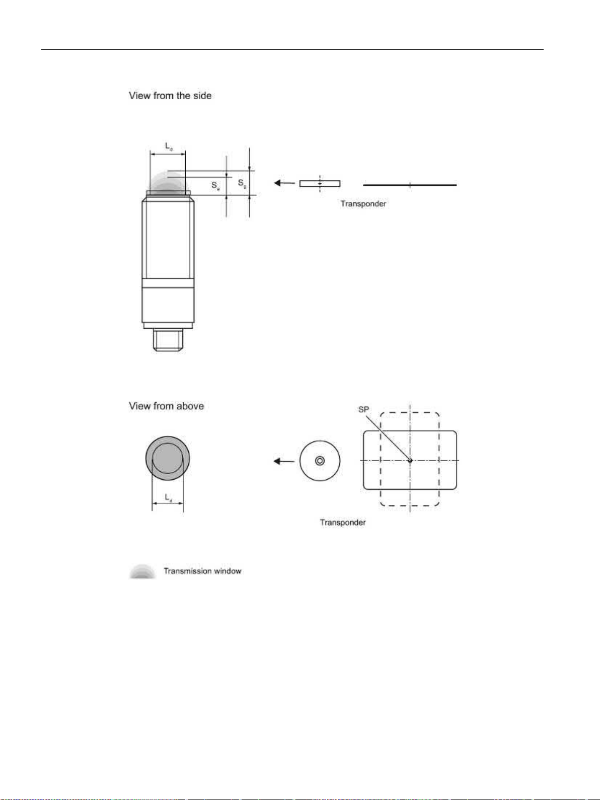
Planning the RF200 system
Sa
Operating distance between transponder and reader
sponder, at which the transmission can still function under normal conditions)
L
Diameter of a transmission window
SP
Intersection of the axes of symmetry of the transponder
4.1 Fundamentals of application planning
Sg Limit distance (maximum clear distance between upper surface of the reader and the tran-
Figure 4-1 RF210R/RF220R transmission window
The figure below shows the transmission window of the SIMATIC RF240R and SIMATIC
RF260R readers between transponder and reader:
SIMATIC RF200
28 System Manual, 03/2019, J31069-D0227-U001-A11-7619
Page 29
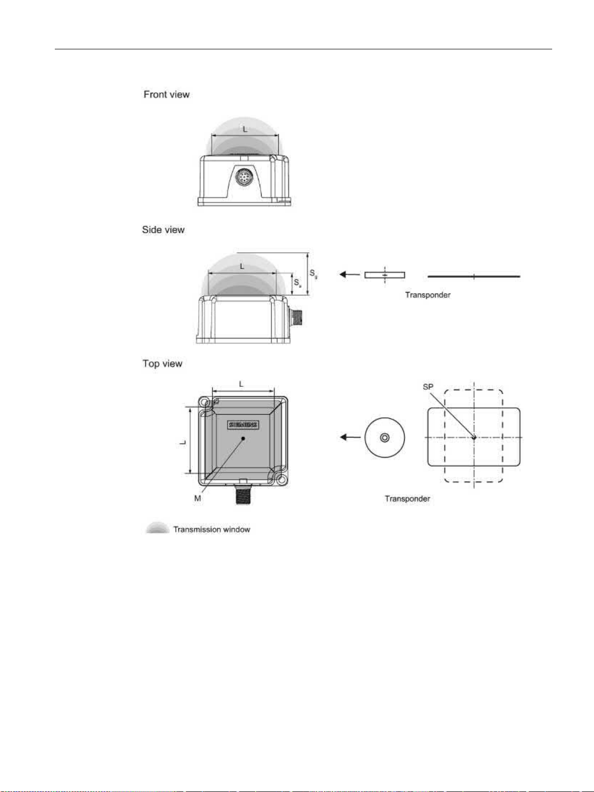
Planning the RF200 system
Sa
Operating distance between transponder and reader
sponder, at which the transmission can still function under normal conditions)
L
Length of a transmission window
M
Field centerpoint
4.1 Fundamentals of application planning
Sg Limit distance (maximum clear distance between upper surface of the reader and the tran-
Figure 4-2 RF240R/RF260R transmission window
The transponder can be used as soon as the intersection (SP) of the transponder enters the
area of the transmission window.
From the diagrams above, it can also be seen that operation is possible within the area
between S
SIMATIC RF200
System Manual, 03/2019, J31069-D0227-U001-A11-7619
and Sg. The active operating area reduces as the distance increases, and
a
29
Page 30

Planning the RF200 system
W:
Width of the transmission window
L:
Length of the transmission window
4.1 Fundamentals of application planning
shrinks to a single point at distance Sg. Only static mode should thus be used in the area
between S
and Sg.
a
4.1.3 Width of the transmission window
Determining the width of the transmission window
The following approximation formula can be used for practical applications:
Tracking tolerance
The width of the transmission window (W) is particularly important for the mechanical
tracking tolerance. The formula for the dwell time is valid without restriction when W is
observed.
SIMATIC RF200
30 System Manual, 03/2019, J31069-D0227-U001-A11-7619
Page 31

Planning the RF200 system
①
Main field
②
Secondary field
4.1 Fundamentals of application planning
4.1.4 Impact of secondary fields
Secondary fields in the range from 0 mm to 30% of the limit distance (Sg) generally always
exist.
They should, however, only be used during configuration in exceptional cases, since the
read/write distances are very limited. Exact details of the secondary field geometry cannot be
given, since these values depend heavily on the operating distance and the application.
When working in dynamic mode, remember that during the transition from the secondary
field to the main field the presence of the tag is lost temporarily. It is therefore advisable to
select a distance > 30 % of S
.
g
Figure 4-3 Gap in the field resulting from secondary fields
SIMATIC RF200
System Manual, 03/2019, J31069-D0227-U001-A11-7619
31
Page 32

Planning the RF200 system
①
Main field
②
Secondary field
4.1 Fundamentals of application planning
Secondary fields without shielding
The following graphic shows typical primary and secondary fields, if no shielding measures
are taken.
Figure 4-4 Secondary field without shielding
In this arrangement, the reader can also read tags via the secondary field. Shielding is
required in order to prevent unwanted reading via the secondary field, as shown and
described in the following.
SIMATIC RF200
32 System Manual, 03/2019, J31069-D0227-U001-A11-7619
Page 33

Planning the RF200 system
①
Main field
②
Secondary field
4.1 Fundamentals of application planning
Secondary fields with shielding
The following graphic shows typical primary and secondary fields, with metal shielding this
time.
The metal shielding prevents the reader from detecting tags via the secondary field.
Figure 4-5 Secondary field with shielding
SIMATIC RF200
System Manual, 03/2019, J31069-D0227-U001-A11-7619
33
Page 34

Planning the RF200 system
4.1 Fundamentals of application planning
4.1.5 Permissible directions of motion of the transponder
Detection area and direction of motion of the transponder
The transponder and reader have no polarization axis, i.e. the transponder can come in from
any direction, assume any position as parallel as possible to the reader, and cross the
transmission window. The figure below shows the active area for various directions of
transponder motion:
Transmission window
Figure 4-6 Detection areas of the reader for different directions of transponder motion
Direction of motion of the transponder
Detection area L x W
SIMATIC RF200
34 System Manual, 03/2019, J31069-D0227-U001-A11-7619
Page 35

Planning the RF200 system
Note
Note that in a metallic environment the values for the limit distance are reduced.
4.1 Fundamentals of application planning
4.1.6 Operation in static and dynamic mode
Operation in static mode
If working in static mode, the transponder can be operated up to the limit distance (Sg). The
transponder must then be positioned exactly over the reader:
Figure 4-7 Operation in static mode
Operation in dynamic mode
When working in dynamic mode, the transponder moves past the reader. The transponder
can be used as soon as the intersection (SP) of the transponder enters the circle of the
transmission window. In dynamic mode, the operating distance (S
[Operating distances, see section Field data of transponders and readers (Page 38)]
) is of primary importance.
a
Figure 4-8 Operation in dynamic mode
SIMATIC RF200
System Manual, 03/2019, J31069-D0227-U001-A11-7619
35
Page 36

Planning the RF200 system
tV:
Dwell time of the transponder
L:
Length of the transmission window
v
Tag
:
Speed of the transponder (tag) in dynamic mode
0.8:
Constant factor used to compensate for temperature influence and production tolerances
tV::
Dwell time of the data memory in the field of the reader
tK:
Communication time between transponder and communication module
4.1 Fundamentals of application planning
4.1.7 Dwell time of the transponder
The dwell time is the time in which the transponder remains within the transmission window
of the reader. The reader can exchange data with the transponder during this time.
The dwell time is calculated as follows:
The dwell time can be of any duration in static mode. The dwell time must be sufficiently long
to allow communication with the transponder.
The dwell time is defined by the system environment in dynamic mode. The volume of data
to be transferred must be matched to the dwell time or vice versa. As a general rule:
SIMATIC RF200
36 System Manual, 03/2019, J31069-D0227-U001-A11-7619
Page 37

Planning the RF200 system
4.1 Fundamentals of application planning
4.1.8 Communication between communication module, reader and transponder
Aids for calculating the data transmission times
User-friendly calculation tools are available for the communications modules ASM 456,
RF160C, RF170C and RF180C to calculate data transfer times. The calculation tools can be
found on the DVD "Ident Systems Software & Documentation", article number 6GT20802AA20.
Figure 4-9 User interface of the calculation tool for command processing time
Aids for calculating the field data
The free "TIA Selection Tool" configurator also supports you during field data collection.
Using this tool, among other things, you can calculate the operating distance (S
distance (S
SIMATIC RF200
System Manual, 03/2019, J31069-D0227-U001-A11-7619
) and transmission window (L).
g
), limit
a
37
Page 38

Planning the RF200 system
Note
Transmission gaps
If the minimum operating distance (S
center of the field. Communication with the transponder is not possible in the transmission
gap.
Note
Possible reader-transponder combinations
The tables of the following section show the possible reader
4.2 Field data of transponders and readers
4.2 Field data of transponders and readers
The following tables show the field data for all SIMATIC RF200 components of transponders
and readers. This makes the correct selection of a transponder and reader particularly easy.
All technical data listed is typical data and is applicable for an ambient room temperature of
between 0 °C and +50 °C, a supply voltage of between 22 V and 27 V DC as well as an
environment free of metal.
temperature conditions.
If the entire voltage range at the reader of 20 VDC to 30 VDC and/or the entire temperature
range of transponders and readers is used, the field data is subject to further tolerances.
Tolerances of ±20 % are permitted due to production or
) is not observed, a transmission gap can occur in the
a
-transponder combinations.
SIMATIC RF200
38 System Manual, 03/2019, J31069-D0227-U001-A11-7619
Page 39

Planning the RF200 system
Length of the transmis-
sion window (Ld)
Operating distance (Sa)
Limit distance (Sg)
MDS D124
25
1 ... 18
20
MDS D127 1) 3 0 ... 2
2
MDS D160
20
1 ... 10
12
MDS D324
20
1 ... 8
9
MDS D421 5 0 ... 3
4
MDS D422 8 1 ... 9
10
MDS D423
20
2 ... 10
12
MDS D424
24
1 ... 16
18
MDS D425
12
1 ... 6
7
MDS D428
20
1 ... 10
11
MDS D460 8 1 … 8
9
MDS D521 5 0 ... 3
4
MDS D522 8 1 ... 8
9
MDS D522
Special variants
MDS D524
20
1 ... 15
17
MDS D525
12
1 ... 6
7
MDS D528
15
1 ... 10
11
MDS D560 8 1 ... 8
9
1)
All dimensions in mm.
4.2 Field data of transponders and readers
4.2.1 Field data
The limit distances (Sg) and operating distances (Sa) along with the length of the
transmission window for each reader-transponder combination are listed in the tables below.
Table 4- 1 SIMATIC RF210R field data
The transponder is only suitable for static mode.
8 1 ... 8 9
SIMATIC RF200
System Manual, 03/2019, J31069-D0227-U001-A11-7619
39
Page 40

Planning the RF200 system
Length of the transmis-
sion window (Ld)
Operating distance (Sa)
Limit distance (Sg)
MDS D124
35
1 ... 28
31
MDS D126
45
2 ... 30
35
MDS D160
20
1 ... 20
22
MDS D324
30
2 ... 21
25
MDS D422
18
1 ... 12
14
MDS D423
30
2 ...24
28
MDS D424
30
2 ... 25
29
MDS D425
20
1 ... 11
13
MDS D426
40
2 ... 25
30
MDS D428
25
1 ... 18
21
MDS D460
25
1 ... 18
20
MDS D522
15
1 ... 10
12
MDS D522
Special variants
MDS D524
25
2 ... 22
25
MDS D525
20
1 ... 11
13
MDS D526
30
2 ... 25
30
MDS D528
20
1 ... 15
20
MDS D560
25
1 ... 18
21
All dimensions in mm.
4.2 Field data of transponders and readers
Table 4- 2 SIMATIC RF220R field data
15 1 ... 10 12
SIMATIC RF200
40 System Manual, 03/2019, J31069-D0227-U001-A11-7619
Page 41

Planning the RF200 system
Length of the transmis-
sion window (L)
Operating distance (Sa)
Limit distance (Sg)
MDS D100
100
2 ... 84
95
MDS D124
65
2 ... 53
60
MDS D126
80
2 ... 57
65
MDS D160
50
1 ... 33
37
MDS D165
105
2 ... 80
94
MDS D200
90
2 ... 69
78
MDS D261
70
2 ... 60
70
MDS D324
55
1 ... 36
40
MDS D400
95
2 ... 80
90
MDS D422
25
1 ... 12
15
MDS D423
45
2 ... 35
40
MDS D424
75
1 ... 47
53
MDS D425
30
1 ... 15
17
MDS D426
65
2 ... 45
55
MDS D428
50
1 ... 30
34
MDS D460
50
1 ... 30
34
MDS D522
20
1 ... 10
12
MDS D522
Special variants
MDS D524
60
1 ... 45
55
MDS D525
30
1 ... 15
17
MDS D526
60
2 ... 45
55
MDS D528
40
1 ... 30
35
MDS D560
50
1 ... 30
34
All dimensions in mm.
4.2 Field data of transponders and readers
Table 4- 3 SIMATIC RF240R field data
20 1 ... 10 12
SIMATIC RF200
System Manual, 03/2019, J31069-D0227-U001-A11-7619
41
Page 42

Planning the RF200 system
Length of the transmis-
sion window (Ld)
Operating distance (Sa)
Limit distance (Sg)
MDS D100
80
5 ... 95
115
MDS D124
55
2 ... 60
75
MDS D126
150
2 ... 80
95
MDS D139
75
5 ... 90
105
MDS D160
50
2 ... 35
45
MDS D165
140
5 ... 95
110
MDS D200
130
5 ... 90
100
MDS D261
100
2 ... 90
110
MDS D324
50
5 ... 60
70
MDS D339
110
2 ... 85
100
MDS D400
140
10 ... 95
110
MDS D423
50
2 ... 35
45
MDS D424
50
2 ... 70
80
MDS D425
40
2 ... 25
30
MDS D426
110
2 ... 80
95
MDS D428
40
2 ... 40
50
MDS D460
50
2 ... 30
40
MDS D524
50
2 ... 65
80
MDS D525
40
2 ... 25
30
MDS D526
110
2 ... 80
95
MDS D528
40
2 ... 40
45
MDS D560
50
2 ... 35
45
All dimensions in mm.
4.2 Field data of transponders and readers
Table 4- 4 Field data SIMATIC RF250R, with ANT 1
SIMATIC RF200
42 System Manual, 03/2019, J31069-D0227-U001-A11-7619
Page 43

Planning the RF200 system
Length of the transmis-
sion window (Ld)
Operating distance (Sa)
Limit distance (Sg)
MDS D124
40
1 ... 32
40
MDS D126
65
0 ... 47
60
MDS D160
24
1 ... 23
30
MDS D324
32
1 ... 22
35
MDS D422
20
0 ... 12
15
MDS D423
35
0 ... 24
30
MDS D424
40
0 ... 34
48
MDS D425
22
1 ... 12
20
MDS D426
65
0 ... 44
58
MDS D428
20
1 ... 20
32
MDS D460
24
1 ... 21
27
MDS D522
20
1 ... 12
15
MDS D522
Special variants
MDS D524
40
1 ... 35
40
MDS D525
22
1 ... 12
20
MDS D526
45
2 ... 35
45
MDS D528
20
1 ... 20
25
MDS D560
24
0 ... 21
27
All dimensions in mm.
Length of the transmis-
sion window (Ld)
Operating distance (Sa)
Limit distance (Sg)
MDS D117 2 0 ... 2
3
MDS D127 3 0 ... 2
3
MDS D421 3 0 ... 3
4
MDS D521 3 0 ... 3
4
All dimensions in mm.
4.2 Field data of transponders and readers
Table 4- 5 Field data SIMATIC RF250R, with ANT 3
20 1 ... 12 15
Table 4- 6 Field data SIMATIC RF250R, with ANT 3S
SIMATIC RF200
System Manual, 03/2019, J31069-D0227-U001-A11-7619
43
Page 44

Planning the RF200 system
Length of the transmis-
sion window (Ld)
Operating distance (Sa)
Limit distance (Sg)
MDS D117 2 0 ... 2
3
MDS D127 3 0 ... 3
4
MDS D421 3 0 ... 3
4
MDS D521 3 0 ... 3
4
All dimensions in mm.
Length of the transmis-
sion window (Ld)
Operating distance (Sa)
Limit distance (Sg)
MDS D117 3 0 ... 3
4
MDS D127 4 0 ... 4
5
MDS D160
18
0 ... 12
17
MDS D421
10
0 ... 2
3
MDS D422
22
0 ... 7
10
MDS D425
12
0 ... 8
10
MDS D428
18
1 ... 8
12
MDS D460
16
1 ... 10
14
MDS D521
10
0 ... 3
4
MDS D522
10
1 ... 7
9
MDS D522
Special variants
MDS D525
12
1 ... 8
10
MDS D528
15
1 ... 8
12
MDS D560
16
1 ... 10
14
All dimensions in mm.
4.2 Field data of transponders and readers
Table 4- 7 Field data SIMATIC RF250R, with ANT 8
Table 4- 8 Field data SIMATIC RF250R, with ANT 12
10 1 ... 7 9
SIMATIC RF200
44 System Manual, 03/2019, J31069-D0227-U001-A11-7619
Page 45

Planning the RF200 system
Length of the transmis-
sion window (Ld)
Operating distance (Sa)
Limit distance (Sg)
MDS D117 3 0 ... 2
3
MDS D127 4 0 ... 3
4
MDS D160
15
0 ... 11
13
MDS D421 9 0 ... 2
3
MDS D422
20
0 ... 5
6
MDS D425
10
1 ... 6
8
MDS D428
16
1 ... 10
12
MDS D460
14
1 ... 8
10
MDS D521 9 0 ... 2
3
MDS D522 9 1 ... 5
7
MDS D522
Special variant
MDS D525
10
1 ... 8
10
MDS D528
14
1 ... 10
12
MDS D560
14
1 ... 11
14
All dimensions in mm.
Length of the transmis-
sion window (Ld)
Operating distance (Sa)
Limit distance (Sg)
MDS D124
26
0 ... 24
37
MDS D160
22
1 ... 18
26
MDS D324
30
1 ... 18
27
MDS D421
16
0 ... 3
5
MDS D422
24
1 ... 8
14
MDS D423
21
1 ... 15
18
MDS D424
26
1 ... 27
36
MDS D425
19
1 ... 11
16
MDS D428
19
1 ... 18
25
MDS D460
19
1 ... 17
21
MDS D521 6 0 ... 4
5
MDS D522
15
1 ... 10
12
MDS D522
Special variants
MDS D524
30
1 ... 25
30
MDS D525
19
1 ... 11
16
MDS D528
20
1 ... 15
20
MDS D560
19
1 ... 17
21
All dimensions in mm.
4.2 Field data of transponders and readers
Table 4- 9 Field data SIMATIC RF250R, with ANT 12 (stainless steel variant)
9 1 ... 6 8
Table 4- 10 Field data SIMATIC RF250R, with ANT 18
SIMATIC RF200
System Manual, 03/2019, J31069-D0227-U001-A11-7619
15 1 ... 10 12
45
Page 46

Planning the RF200 system
Length of the transmis-
sion window (Ld)
Operating distance (Sa)
Limit distance (Sg)
MDS D124
22
1 ... 28
32
MDS D160
20
1 ... 17
20
MDS D324
28
1 ... 24
27
MDS D421
15
0 ... 3
5
MDS D422
22
0 ... 8
10
MDS D423
21
1 ... 22
25
MDS D424
25
1 ... 30
34
MDS D425
18
1 ... 13
15
MDS D428
18
1 ... 15
18
MDS D460
16
1 ... 15
18
MDS D521 5 0 ... 3
5
MDS D522
14
1 ... 10
12
MDS D522
Special variant
MDS D524
30
1 ... 26
30
MDS D525
18
1 ... 13
16
MDS D528
18
1 ... 17
20
MDS D560
18
1 ... 17
21
All dimensions in mm.
4.2 Field data of transponders and readers
Table 4- 11 Field data SIMATIC RF250R, with ANT 18 (stainless steel variant)
12 1 ... 7 9
SIMATIC RF200
46 System Manual, 03/2019, J31069-D0227-U001-A11-7619
Page 47

Planning the RF200 system
Length of the transmis-
sion window (Ld)
Operating distance (Sa)
Limit distance (Sg)
MDS D124
40
1 ... 35
48
MDS D126
45
0 ... 47
60
MDS D160
25
1 ... 23
30
MDS D324
35
1 ... 22
30
MDS D422
20
0 ... 12
15
MDS D423
35
0 ... 18
30
MDS D424
35
0 ... 34
48
MDS D425
20
1 ... 12
20
MDS D426
45
0 ... 44
58
MDS D428
20
1 ... 20
32
MDS D460
25
1 ... 21
27
MDS D522
18
1 ... 12
15
MDS D522
Special variants
MDS D524
35
1 ... 35
40
MDS D526
45
2 ... 35
45
MDS D528
20
1 ... 20
25
MDS D560
25
1 ... 21
27
All dimensions in mm.
4.2 Field data of transponders and readers
Table 4- 12 Field data SIMATIC RF250R, with ANT 30
18 1 ... 12 15
SIMATIC RF200
System Manual, 03/2019, J31069-D0227-U001-A11-7619
47
Page 48

Planning the RF200 system
Length of the transmis-
sion window (Ld)
Operating distance (Sa)
Limit distance (Sg)
MDS D124
40
1 ... 34
38
MDS D126
45
0 ... 45
50
MDS D160
25
1 ... 22
25
MDS D324
35
1 ... 30
35
MDS D422
20
0 ... 12
15
MDS D423
35
1 ... 28
32
MDS D424
35
1 ... 40
45
MDS D425
20
1 ... 17
20
MDS D426
45
1 ... 40
48
MDS D428
20
1 ... 22
26
MDS D460
25
1 ... 24
27
MDS D522
18
1 ... 12
15
MDS D522
Special variant
MDS D524
35
1 ... 35
42
MDS D526
45
2 ... 44
50
MDS D528
20
1 ... 22
25
MDS D560
25
1 ... 22
25
All dimensions in mm.
4.2 Field data of transponders and readers
Table 4- 13 Field data SIMATIC RF250R, with ANT 30 (stainless steel variant)
18 1 ... 12 15
SIMATIC RF200
48 System Manual, 03/2019, J31069-D0227-U001-A11-7619
Page 49

Planning the RF200 system
Length of the transmis-
sion window (L)
Operating distance (Sa)
Limit distance (Sg)
MDS D100
90
2 ... 110
130
MDS D124
60
2 ... 80
85
MDS D126
80
2 ... 75
100
MDS D139
90
2 ... 80
110
MDS D160
50
2 ... 40
45
MDS D165
120
2 ... 120
135
MDS D200
120
2 ... 100
120
MDS D261
80
2 ... 75
90
MDS D324
50
2 ... 60
70
MDS D339
110
5 ... 65
80
MDS D400
140
2 ... 110
140
MDS D423
50
2 ... 40
45
MDS D424
50
2 ... 60
70
MDS D426
75
2 ... 70
85
MDS D428
45
2 ... 40
45
MDS D460
45
2 ... 40
45
MDS D524
50
2 ... 60
70
MDS D526
80
2 ... 70
85
MDS D528
45
2 ... 35
40
MDS D560
45
2 ... 40
45
All dimensions in mm.
4.2 Field data of transponders and readers
Table 4- 14 SIMATIC RF260R field data
SIMATIC RF200
System Manual, 03/2019, J31069-D0227-U001-A11-7619
49
Page 50

Planning the RF200 system
Length of the transmission window
(L)
Operating distance
(Sa)
Limit distance (Sg)
in the x direction
(Lx)
in the y direction
(Ly)
MDS D100 1)
140
100
10 ... 160
200
MDS D124
80
80
2 ... 110
130
MDS D126
180
140
2 ... 135
160
MDS D139
140
90
5 ... 150
190
MDS D160
80
40
2 ... 55
70
MDS D165 1)
200
140
10 ... 160
190
MDS D200 2)
200
160
20 ... 140
185
MDS D261 3)
190
120
20 ... 110
150
MDS D324
100
60
2 ... 85
110
MDS D339
290
140
5 ... 150
170
MDS D400
240
120
10 ... 170
200
MDS D423
110
60
5 ... 60
70
MDS D424
100
70
2 ... 100
140
MDS D425
80
45
2 ... 30
40
MDS D426
220
160
2 ... 145
175
MDS D428
80
50
2 ... 60
88
MDS D460
80
70
2 ... 55
70
MDS D524
100
70
2 ... 110
130
MDS D525
80
45
2 ... 30
40
MDS D526
220
160
2 ... 135
165
MDS D528
80
50
2 ... 60
85
MDS D560
80
70
2 ... 55
70
All dimensions in mm.
1)
2)
3)
starting at an ambient temperature of 50 °C.
4.2 Field data of transponders and readers
Table 4- 15 Field data SIMATIC RF280R
Be aware that the minimum distance must be increased 10 mm starting at 40 °C ambient tempera-
ture.
Be aware that the minimum distance of the reader to the transponder must be increased approxi-
mately 6 mm every 5 °C starting at an ambient temperature of 25 °C and approximately 15 mm
starting at an ambient temperature of 50 °C.
Be aware that the minimum distance of the reader to the transponder must be increased approxi-
mately 3 mm every 5 °C starting at an ambient temperature of 25 °C and approximately 14 mm
SIMATIC RF200
50 System Manual, 03/2019, J31069-D0227-U001-A11-7619
Page 51

Planning the RF200 system
Length of the transmis-
sion window (L)
Operating distance (Sa)
Limit distance (Sg)
MDS D100
150
10 ... 150
200
MDS D124
60
0 ... 100
140
MDS D126
150
5 ... 110
150
MDS D139
110
5 ... 160
220
MDS D160
50
0 ... 65
90
MDS D165
150
10 ... 150
200
MDS D200
150
10 ... 130
180
MDS D261
120
5 ... 130
180
MDS D324
50
0 ... 90
130
MDS D339
110
5 ... 130
170
MDS D400
150
10 ... 130
180
MDS D423
50
10 ... 60
85
MDS D424
60
0 ... 90
130
MDS D426
110
5 ... 100
140
MDS D428
60
0 ... 55
80
MDS D460
50
0 ... 60
85
MDS D524
60
0 ... 90
130
MDS D526
110
5 ... 100
140
MDS D528
60
0 ... 55
80
MDS D560
50
0 ... 60
85
All dimensions in mm.
4.2 Field data of transponders and readers
Table 4- 16 Field data SIMATIC RF285R, with ANT D1
SIMATIC RF200
System Manual, 03/2019, J31069-D0227-U001-A11-7619
51
Page 52

Planning the RF200 system
Length of the transmis-
sion window (L)
Operating distance (Sa)
Limit distance (Sg)
MDS D100
320
0 ... 350
450
MDS D124
300
0 ... 180
240
MDS D126
320
0 ... 300
380
MDS D139
320
0 ... 350
450
MDS D160
300
0 ... 110
140
MDS D165
320
0 ... 300
380
MDS D200
320
0 ... 350
450
MDS D261
320
0 ... 300
380
MDS D324
300
0 ... 150
200
MDS D339
320
0 ... 280
350
MDS D400
320
0 ... 320
420
MDS D424
300
0 ... 180
240
MDS D426
300
0 ... 250
320
MDS D460
300
0 ... 100
120
MDS D524
300
0 ... 180
240
MDS D526
320
0 ... 250
320
MDS D528
300
0 ... 110
140
All dimensions in mm.
Length of the transmission window
(L)
Operating distance
(Sa)
Limit distance (Sg)
X direction
Y direction
MDS D100
420
520
0 ... 450
550
MDS D124
400
500
0 ... 200
280
MDS D126
420
520
0 ... 350
450
MDS D139
420
520
0 ... 450
550
MDS D165
420
520
0 ... 350
450
MDS D200
420
520
0 ... 350
450
MDS D261
420
520
0 ... 300
400
MDS D324
400
500
0 ... 180
240
MDS D339
420
520
0 ... 350
450
MDS D400
420
520
0 ... 400
500
MDS D424
400
500
0 ... 200
280
MDS D426
420
520
0 ... 300
380
MDS D524
400
500
0 ... 200
250
MDS D526
420
520
0 ... 300
380
All dimensions in mm.
4.2 Field data of transponders and readers
Table 4- 17 Field data SIMATIC RF285R, with ANT D5
Table 4- 18 Field data SIMATIC RF285R, with ANT D6
SIMATIC RF200
52 System Manual, 03/2019, J31069-D0227-U001-A11-7619
Page 53

Planning the RF200 system
Length of the transmis-
sion window (L)
Operating distance (Sa)
Limit distance (Sg)
MDS D100
150
10 ... 180
250
MDS D124
60
0 ... 100
140
MDS D126
150
5 ... 110
150
MDS D139
110
5 ... 160
220
MDS D160
50
0 ... 65
90
MDS D165
150
10 ... 180
250
MDS D200
150
10 ... 170
240
MDS D261
120
5 ... 130
180
MDS D324
50
0 ... 90
130
MDS D339
110
5 ... 130
170
MDS D400
150
10 ... 170
240
MDS D423
50
10 ... 60
85
MDS D424
60
0 ... 90
130
MDS D426
110
5 ... 100
140
MDS D460
60
0 ... 60
85
MDS D524
60
0 ... 90
130
MDS D526
100
5 ... 100
140
MDS D528
60
0 ... 55
80
MDS D560
50
0 ... 60
85
All dimensions in mm.
4.2 Field data of transponders and readers
Table 4- 19 Field data SIMATIC RF290R, with ANT D1 (at 2 W)
SIMATIC RF200
System Manual, 03/2019, J31069-D0227-U001-A11-7619
53
Page 54

Planning the RF200 system
Length of the transmis-
sion window (L)
Operating distance (Sa)
Limit distance (Sg)
MDS D100
320
0 ... 400
500
MDS D124
300
0 ... 200
280
MDS D126
320
0 ... 350
400
MDS D139
320
0 ... 400
500
MDS D160
300
0 ... 130
180
MDS D165
320
0 ... 350
450
MDS D200
320
0 ... 400
500
MDS D261
320
0 ... 300
400
MDS D324
300
0 ... 200
280
MDS D339
320
0 ... 300
380
MDS D400
320
0 ... 400
500
MDS D424
300
0 ... 200
280
MDS D426
320
0 ... 300
350
MDS D460
300
0 ... 120
160
MDS D524
300
0 ... 200
280
MDS D528
320
0 ... 300
350
MDS D560
300
0 ... 120
160
All dimensions in mm.
Length of the transmission window
(L)
Operating distance
(Sa)
Limit distance (Sg)
X direction
Y direction
MDS D100
520
420
0 ... 550
650
MDS D124
500
400
0 ... 220
300
MDS D126
520
420
0 ... 400
500
MDS D139
520
420
0 ... 500
600
MDS D165
520
420
0 ... 400
500
MDS D200
520
420
0 ... 500
600
MDS D261
520
420
0 ... 350
450
MDS D324
500
400
0 ... 200
280
MDS D339
520
420
0 ... 400
480
MDS D400
520
420
0 ... 500
650
MDS D424
500
400
0 ... 220
300
MDS D426
520
420
0 ... 350
400
MDS D524
500
400
0 ... 220
300
MDS D526
520
420
0 ... 350
400
All dimensions in mm.
4.2 Field data of transponders and readers
Table 4- 20 Field data SIMATIC RF290R, with ANT D5 (at 4 W)
Table 4- 21 Field data SIMATIC RF290R, with ANT D6 (at 4 W)
SIMATIC RF200
54 System Manual, 03/2019, J31069-D0227-U001-A11-7619
Page 55

Planning the RF200 system
Length of the transmission window
(L)
Operating distance
(Sa)
Limit distance (Sg)
X direction
Y direction
MDS D100
1050
350
0 ... 500
600
MDS D124
1000
300
0 ... 200
280
MDS D126
1050
350
0 ... 400
500
MDS D139
1050
350
0 ... 450
550
MDS D165
1050
350
0 ... 350
450
MDS D200
1050
350
0 ... 450
550
MDS D261
1050
350
0 ... 350
450
MDS D324
1000
300
0 ... 200
280
MDS D339
1050
350
0 ... 300
380
MDS D400
1050
350
0 ... 400
500
MDS D424
1000
300
0 ... 200
280
MDS D426
1050
350
0 ... 350
400
MDS D524
1000
300
0 ... 220
300
MDS D526
1050
350
0 ... 350
400
All dimensions in mm.
4.2 Field data of transponders and readers
Table 4- 22 Field data SIMATIC RF290R, with ANT D10 (at 4 W)
SIMATIC RF200
System Manual, 03/2019, J31069-D0227-U001-A11-7619
55
Page 56

Planning the RF200 system
RF210R
RF220R
RF240R
RF260R
RF280R
MDS D100
--
--
--
≥ 240
≥ 420
MDS D117
--
--
--
--
--
MDS D124
≥ 25
≥ 40
≥ 90
≥ 180
≥ 360
MDS D126
--
≥ 50
≥ 100
≥ 180
≥ 400
MDS D127
≥ 15
--
--
--
--
MDS D139
--
--
--
≥ 200
≥ 450
MDS D160
≥ 20
≥ 25
≥ 70
≥ 150
≥ 300
MDS D165
--
--
--
≥ 240
≥ 500
MDS D200
--
--
--
≥ 240
≥ 500
MDS D261
--
--
--
≥ 200
≥ 400
MDS D324
≥ 25
≥ 40
≥ 90
≥ 180
≥ 360
MDS D339
--
--
--
≥ 200
≥ 450
MDS D400
--
--
--
≥ 240
≥ 500
MDS D421
≥ 10
--
--
--
--
MDS D422
≥ 15
≥ 20
≥ 50
--
--
MDS D423
--
--
≥ 80
≥ 160
≥ 250
MDS D424
≥ 25
≥ 40
≥ 90
≥ 180
≥ 360
MDS D425
≥ 20
≥ 25
≥ 75
--
≥ 250
MDS D426
--
≥ 50
≥ 90
≥ 180
≥ 400
MDS D428
≥ 25
≥ 25
≥ 75
≥ 150
≥ 300
MDS D460
≥ 20
≥ 25
≥ 70
≥ 150
≥ 300
MDS D521
≥ 10
--
--
--
--
MDS D522
≥ 15
≥ 20
≥ 50
--
--
MDS D522
Special variants
MDS D524
≥ 25
≥ 40
≥ 90
≥ 180
≥ 360
MDS D525
≥ 20
≥ 25
≥ 75
--
≥ 250
MDS D526
--
≥ 50
≥ 90
≥ 180
≥ 400
MDS D528
≥ 25
≥ 25
≥ 75
≥ 150
≥ 300
MDS D560
≥ 20
≥ 25
≥ 70
≥ 150
≥ 300
All values are in mm, relative to the operating distance (S
between transponder edge and transponder edge
4.2 Field data of transponders and readers
4.2.2 Minimum clearances
Minimum distance from transponder to transponder
The specified distances refer to a metal-free environment. For a metallic environment, the
specified minimum distances must be multiplied by a factor of 1.5. The transponders
designed specifically for installation in/on metal are an exception to this.
Table 4- 23 Minimum clearances for transponders - Part 1
SIMATIC RF200
56 System Manual, 03/2019, J31069-D0227-U001-A11-7619
≥ 15 ≥ 20 ≥ 50 -- --
) between reader and transponder, and
a
Page 57

Planning the RF200 system
RF250R
1)
ANT 1
ANT 3 /
ANT 30
ANT 3S /
ANT 18
ANT 8
ANT 12
MDS D100
≥ 300
--
--
--
--
MDS D117
--
--
--
≥ 30
≥ 50
MDS D124
≥ 200
≥ 100
≥ 80
--
--
MDS D126
≥ 250
≥ 100
--
--
--
MDS D127
--
--
--
≥ 40
≥ 60
MDS D139
≥ 300
--
--
--
--
MDS D160
≥ 200
≥ 100
≥ 80
--
≥ 60
MDS D165
≥ 300
--
--
--
--
MDS D200
≥ 300
--
--
--
--
MDS D261
≥ 300
--
--
--
--
MDS D324
≥ 200
≥ 100
≥ 80
--
--
MDS D339
≥ 300
--
--
--
--
MDS D400
≥ 300
--
--
--
--
MDS D421
--
--
≥ 50
≥ 30
≥ 40
MDS D422
--
≥ 70
≥ 60
--
≥ 50
MDS D423
≥ 200
≥ 100
≥ 80
--
--
MDS D424
≥ 200
≥ 100
≥ 80
--
--
MDS D425
≥ 150
≥ 80
≥ 60
--
≥ 50
MDS D426
≥ 250
≥ 100
--
--
--
MDS D428
≥ 150
≥ 80
≥ 60
--
≥ 50
MDS D460
≥ 200
≥ 100
≥ 80
--
≥ 60
MDS D521
--
--
≥ 50
≥ 30
≥ 40
MDS D522
--
≥ 70
≥ 60
--
≥ 50
MDS D522
Special variant
MDS D524
≥ 200
≥ 100
≥ 80
--
--
MDS D525
≥ 150
≥ 80
≥ 60
--
≥ 50
MDS D526
≥ 250
≥ 100
--
--
--
MDS D528
≥ 150
≥ 80
≥ 60
--
≥ 50
MDS D560
≥ 200
≥ 100
≥ 80
--
≥ 60
1)
All values are in mm, relative to the operating distance (S
between transponder edge and transponder edge
4.2 Field data of transponders and readers
Table 4- 24 Minimum clearances for transponders - Part 2
Depends on the connected antenna.
SIMATIC RF200
System Manual, 03/2019, J31069-D0227-U001-A11-7619
-- ≥ 70 ≥ 60 -- ≥ 50
) between reader and transponder, and
a
57
Page 58

Planning the RF200 system
RF285R 1)
RF290R
2)
ANT D1
ANT D5
ANT D6
ANT D1
ANT D5
ANT D6
ANT D10
MDS D100
≥ 350
≥ 1000
≥ 1500
≥ 350
≥ 1000
≥ 1500
≥ 2000
MDS D117
--
--
--
--
--
--
--
MDS D124
≥ 250
≥ 800
≥ 1200
≥ 250
≥ 800
≥ 1200
≥ 1800
MDS D126
≥ 300
≥ 1000
≥ 1500
≥ 300
≥ 1000
≥ 1500
≥ 2000
MDS D127
--
--
--
--
--
--
--
MDS D139
≥ 350
≥ 1000
≥ 1500
≥ 350
≥ 1000
≥ 1500
≥ 2000
MDS D160
≥ 250
≥ 800
≥ 1200
≥ 250
≥ 800
≥ 1200
≥ 1800
MDS D165
≥ 350
≥ 1000
≥ 1500
≥ 350
≥ 1000
≥ 1500
≥ 2000
MDS D200
≥ 350
≥ 1000
≥ 1500
≥ 350
≥ 1000
≥ 1500
≥ 2000
MDS D261
≥ 350
≥ 1000
≥ 1500
≥ 350
≥ 1000
≥ 1500
≥ 2000
MDS D324
≥ 250
≥ 800
≥ 1200
≥ 250
≥ 800
≥ 1200
≥ 1800
MDS D339
≥ 350
≥ 1000
≥ 1500
≥ 350
≥ 1000
≥ 1500
≥ 2000
MDS D400
≥ 350
≥ 1000
≥ 1500
≥ 350
≥ 1000
≥ 1500
≥ 2000
MDS D421
--
--
--
--
--
--
--
MDS D422
--
--
--
--
--
--
--
MDS D423
≥ 250
--
--
≥ 250
--
--
--
MDS D424
≥ 250
≥ 800
≥ 1200
≥ 250
≥ 800
≥ 1200
≥ 1800
MDS D425
≥ 200
--
--
≥ 200
--
--
--
MDS D426
≥ 300
≥ 800
≥ 1200
≥ 300
≥ 800
≥ 1200
≥ 1800
MDS D428
≥ 200
--
--
≥ 200
--
--
--
MDS D460
≥ 250
≥ 800
--
≥ 250
≥ 800
--
--
MDS D521
--
--
--
--
--
--
--
MDS D522
--
--
--
--
--
--
--
MDS D522
Special variants
MDS D524
≥ 250
≥ 800
≥ 1200
≥ 250
≥ 800
≥ 1200
≥ 1800
MDS D525
≥ 200
--
--
≥ 200
--
--
--
MDS D526
≥ 300
≥ 800
≥ 1200
≥ 300
≥ 800
≥ 1200
≥ 1800
MDS D528
≥ 200
--
--
≥ 200
--
--
--
MDS D560
≥ 250
≥ 800
--
≥ 250
≥ 800
--
--
1)
2)
All values are in mm, relative to the operating distance (S
between transponder edge and transponder edge
4.2 Field data of transponders and readers
Table 4- 25 Minimum clearances for transponders - Part 3
Depends on the connected antenna.
Depends on the connected antenna.
SIMATIC RF200
58 System Manual, 03/2019, J31069-D0227-U001-A11-7619
-- -- -- -- -- -- --
) between reader and transponder, and
a
Page 59

Planning the RF200 system
RF210R to
RF210R
RF220R to
RF220R
RF240R to
RF240R
RF260R to
RF260R
RF280R to
RF280R
ers: ≥ 200
ers: ≥ 250
ers: ≥ 500
All values are in mm
ANT x to ANT x
with RF250R
ANT x to ANT x
with RF285R
ANT Dx to ANT Dx
with RF290R
≥ 600 1)
ANT D6: ≥ 2000
ANT D10: ≥ 2000
All values are in mm
1)
With a maximum transmit power of 2 W.
Note
Effect on inductive fields by not maintaining the minimum distances of the readers
If the values fall below those specified in the "minimum distance readers or antennas", there
is a risk of the function being affected by inductive fields. In this case, the
would increase unpredictably or a command would be aborted with an error.
Keeping to the values specified in the "Minimum distance readers or antennas" table is
therefore essential.
4.2 Field data of transponders and readers
Minimum distance from reader to reader
The information below relates to the minimum clearances between devices mounted next to
each other.
Table 4- 26 Minimum distances reader
≥ 60 ≥ 100 with 2 readers:
≥ 120
with multiple read-
Table 4- 27 Minimum distances to readers or antennas
Depending on the transponder
used.
You can find the values in the
"Minimum clearances" sections
of the ANT x.
ANT D1: ≥ 600 ANT D1 bei 2 Antennen:
ANT D5: ≥ 1500
ANT D6: ≥ 1500
with 2 readers:
≥ 150
with multiple read-
ANT D1 bei mehreren Anten-
ANT D5: ≥ 2000
with 2 readers:
≥ 400
with multiple read-
≥ 600 1)
nen:
If the specified minimum distance cannot be complied with due to the physical configuration,
the SET-ANT command can be used to activate and deactivate the HF field of the reader.
The application software must be used to ensure that only one reader is active (antenna is
switched on) at a time.
SIMATIC RF200
System Manual, 03/2019, J31069-D0227-U001-A11-7619
data transfer time
59
Page 60

Planning the RF200 system
Representation
Description
Problem:
Remedy:
4.3 Installation guidelines
4.3 Installation guidelines
4.3.1 Overview
The transponder and reader complete with their antennas are inductive devices. Any type of
metal in the vicinity of these devices affects their functionality. Some points need to be
considered during planning and installation if the values described in the "Field data
(Page 39)" section are to retain their validity:
● Minimum spacing between two readers or their antennas
● Minimum distance between two adjacent data memories
● Metal-free area for flush-mounting of readers or their antennas and transponders in metal
● Mounting of multiple readers or their antennas on metal frames or racks
The following sections describe the impact on the operation of the RFID system when
mounted in the vicinity of metal.
4.3.2 Reduction of interference due to metal
Table 4- 28 Interference due to metal rack
A metal rack is located above the
transmission window of the reader.
This affects the entire field. In particular, the transmission window
between reader and transponder is
reduced.
The transmission window is no
longer affected if the transponder is
mounted differently.
SIMATIC RF200
60 System Manual, 03/2019, J31069-D0227-U001-A11-7619
Page 61

Planning the RF200 system
Representation
Description
Problem:
Remedy:
Remedy:
4.3 Installation guidelines
Table 4- 29 Flush-mounting of transponders and readers
Flush-mounting of transponders and
readers is possible in principle.
However, the size of the transmission window is significantly reduced.
The following measures can be
used to counteract the reduction of
the window:
Enlargement of the non-metallic
spacer below the transponder
and/or reader.
The transponder and/or reader are
10 to 20 mm higher than the metal
surround.
(The value x ≥ 100 mm is valid, for
example, for RF260R. It indicates
that, for a distance x ≥ 100 mm, the
reader can no longer be significantly
affected by metal.)
Increase the distances a, b to metal.
The following rule of thumb can be
used:
• Increase a, b by a factor of 2 to 3
over the values specified for
metal-free areas
• Increasing a, b has a greater
effect for readers or transponders with a large limit distance
than for readers or transponders
with a small limit distance.
SIMATIC RF200
System Manual, 03/2019, J31069-D0227-U001-A11-7619
61
Page 62

Planning the RF200 system
Representation
Description
Problem:
Interaction between readers
Remedy:
Remedy:
Remedy:
4.3 Installation guidelines
Mounting of several readers on metal frames or racks
Any reader mounted on metal couples part of the field to the metal frame. There is normally
no interaction as long as the minimum distance D and metal-free areas a, b are maintained.
However, interaction may take place if an iron frame is positioned unfavorably. Longer data
transfer times or sporadic error messages at the communication module are the result.
Table 4- 30 Mounting of several readers on metal frames or racks
Increase the distance D between the two readers.
Introduce one or more iron struts in order to shortcircuit the stray fields.
Insert a non-metallic spacer of 20 to 40 millimeter
thickness between the reader and the iron frame. This
will significantly reduce the induction of stray fields on
the rack:
4.3.3 Effects of metal on different transponders and readers
Mounting different transponders and readers on metal or flush-mounting
SIMATIC RF200
62 System Manual, 03/2019, J31069-D0227-U001-A11-7619
Certain conditions have to be observed when mounting the transponders and readers on
metal or flush-mounting. For more information, please refer to the descriptions of the
individual transponders and readers in the relevant section.
Page 63

Planning the RF200 system
Note
Possible reader-transponder combinations
The tables of the following section show the possible reader-transponder combinations.
4.3 Installation guidelines
4.3.4 Impact of metal on the transmission window
In general, the following points should be considered when mounting RFID components:
● Direct mounting on metal is allowed only in the case of specially approved transponders.
● Flush-mounting of the components in metal reduces the field data; a test is recommended
in critical applications.
● When working inside the transmission window, make sure that no metal rail (or similar
part) intersects the transmission field.
The metal rail would affect the field data.
● With readers with a large antenna surface, for reasons of communication reliability, when
the transponders are flush-mounted in metal, a metal-free space around the transponders
is recommended. This metal-free space should match the size of the antenna surface.
● The reduction of field data is also based on the minimum distance between the reader
and transponder. The respective recommendations are listed in the following table.
The impact of metal on the field data (S
, Sa, L) is shown in a table in this section. The
g
values in the tables describe field data reduction and show the reduced range as a
percentage. The range relates to use in a non-metallic environment. A value of 100% means
no influence on the range.
SIMATIC RF200
System Manual, 03/2019, J31069-D0227-U001-A11-7619
63
Page 64

Planning the RF200 system
Case
Diagram
Description
4.3 Installation guidelines
4.3.4.1 RF210R
The RF210R can be flush-mounted in metal. Please allow for a possible reduction in the field
data values. To avoid reduction in the case of d), the distance a should be ≥ 10 mm.
The following table shows the different installation example of the reader with and without a
metallic environment:
Table 4- 31 Installation examples RF210R
a)
b)
c)
Reader metal-free
Reader on metal,
distance from metal ≥ 12 mm
Reader in metal,
flush against M18 nut
d)
SIMATIC RF200
Reader in metal,
all around
64 System Manual, 03/2019, J31069-D0227-U001-A11-7619
Page 65

Planning the RF200 system
Transponder
Reader without direct
metal influence
(Case a, b and d)
Reader flush-
mounted in metal
(Case c)
MDS D124
Metal-free
100
82
On metal, distance 15 mm
90
90
distance all round 15 mm
MDS D127
distance all round 0 mm
MDS D160
Metal-free
100
95
On metal, distance 10 mm
100
95
MDS D324
Metal-free
100
90
On metal, distance 15 mm
90
90
MDS D421
Metal-free
100
90
MDS D422
Metal-free
100
80
MDS D423
Metal-free
100
90
On metal, distance 0 mm
110
100 2)
distance all round 10 mm
MDS D424
Metal-free
100
60
On metal, distance 15 mm
90
80
distance all round 25 mm
MDS D425
Metal-free
100
85
On metal, distance 0 mm
100
85
MDS D428
Metal-free
100
90
On metal, distance 0 mm
100
80
MDS D460
Metal-free
100
90
On metal, distance 25 mm
100
90
MDS D521
Metal-free
100
90
distance all round 0 mm
4.3 Installation guidelines
Table 4- 32 Reduction of field data due to metal, range as %: Transponder and RF210R
1)
Flush-mounted in metal;
Flush-mounted in metal;
1)
1)
Flush-mounted in metal;
distance all round 25 mm
Flush-mounted in metal;
distance all round 0 mm
Flush-mounted in metal;
distance all round 0 mm
Flush-mounted in metal;
1)
85 80
100 75
80 90
75 50
90 40
2)
95 85
SIMATIC RF200
System Manual, 03/2019, J31069-D0227-U001-A11-7619
Flush-mounted in metal;
85 75
1)
Flush-mounted in metal;
75 50
65
Page 66

Planning the RF200 system
Transponder
Reader without direct
metal influence
(Case a, b and d)
Reader flush-
mounted in metal
(Case c)
MDS D522
Metal-free
100
80
distance all round 0 mm
MDS D522
Special variants
Metal-free
100
80
distance all round 0 mm
MDS D524
Metal-free
100
60
On metal, distance 15 mm
90
80
distance all round 25 mm
MDS D528
Metal-free
100
90
On metal, distance 0 mm
100
80
1)
2)
specifically for mounting in/on metallic surroundings.
4.3 Installation guidelines
Flush-mounted in metal;
Flush-mounted in metal;
1)
90 40
90 40
Flush-mounted in metal;
85 75
Mounting the transponder on or in metal is only possible with the appropriate spacer or if there is
adequate clearance to the metal.
Values of > 100 % related to non metal surroundings can occur if transponders were developed
SIMATIC RF200
66 System Manual, 03/2019, J31069-D0227-U001-A11-7619
Page 67

Planning the RF200 system
Case
Diagram
Description
4.3 Installation guidelines
4.3.4.2 RF220R
The RF220R can be flush-mounted in metal. Please allow for a possible reduction in the field
data values. To avoid reduction in the case of d), the distance a should be ≥ 15 mm.
The following table shows the different installation example of the reader with and without a
metallic environment:
Table 4- 33 Installation examples RF220R
a)
b)
c)
Reader metal-free
Reader on metal,
distance from metal ≥ 12 mm
Reader in metal,
flush against M30 nut
d)
SIMATIC RF200
System Manual, 03/2019, J31069-D0227-U001-A11-7619
Reader in metal,
all round
67
Page 68

Planning the RF200 system
Transponder
Reader without direct
metal influence
(Case a, b and d)
Reader flush-
mounted in metal
(Case c)
MDS D124
Metal-free
100
94
On metal, distance 15 mm
97
89
distance all round 15 mm
MDS D126
Metal-free
100
75
On metal, distance 25 mm
85
70
distance all round 50 mm
MDS D160
Metal-free
100
89
On metal, distance 10 mm
100
89
MDS D324
Metal-free
100
90
On metal, distance 15 mm
97
86
distance all round 25 mm
MDS D422
Metal-free
100
90
distance all round 0 mm
MDS D423
Metal-free
100
90
On metal, distance 0 mm
125 2)
115 2)
distance all round 10 mm
MDS D424
Metal-free
100
93
On metal, distance 15 mm
96
89
distance all round 25 mm
MDS D425
Metal-free
100
90
Screwed onto metal
100
75
distance all round 25 mm
MDS D426
Metal-free
100
90
On metal, distance 25 mm
90
75
distance all round 50 mm
MDS D428
Metal-free
100
94
On metal, distance 0 mm
100
94
MDS D460
Metal-free
100
92
On metal, distance 0 mm
100
92
MDS D522
Metal-free
100
90
distance all round 0 mm
4.3 Installation guidelines
Table 4- 34 Reduction of field data due to metal, range as %: Transponder and RF220R
1)
Tag flush-mounted in metal;
1)
Flush-mounted in metal;
1)
1)
Flush-mounted in metal;
86 83
80 65
93 86
Flush-mounted in metal;
85 85
Flush-mounted in metal;
1)
Flush-mounted in metal;
80 75
86 82
SIMATIC RF200
68 System Manual, 03/2019, J31069-D0227-U001-A11-7619
Flush-mounted in metal;
1)
Flush-mounted in metal;
95 75
80 70
1)
Flush-mounted in metal;
85 85
Page 69

Planning the RF200 system
Transponder
Reader without direct
metal influence
(Case a, b and d)
Reader flush-
mounted in metal
(Case c)
MDS D522
Special variants
Metal-free
100
90
distance all round 0 mm
MDS D524
Metal-free
100
93
On metal, distance 0 mm
96
89
distance all round 0 mm
MDS D526
Metal-free
100
90
On metal, distance 25 mm
90
75
distance all round 50 mm
MDS D528
Metal-free
100
94
On metal, distance 0 mm
100
94
1)
2)
specifically for mounting in/on metallic surroundings.
4.3 Installation guidelines
Flush-mounted in metal;
1)
85 85
Mounting the transponder on or in metal is only possible with the appropriate spacer or if there is
adequate clearance to the metal.
Values of > 100 % related to non metal surroundings can occur if transponders were developed
4.3.4.3 RF240R
The RF240R can be flush-mounted in metal. Please allow for a possible reduction in the field
data values. To avoid reduction, the distance a should be ≥ 20 mm.
Flush-mounted in metal;
1)
Flush-mounted in metal;
86 82
80 70
Figure 4-10 Metal-free space RF240R
SIMATIC RF200
System Manual, 03/2019, J31069-D0227-U001-A11-7619
69
Page 70

Planning the RF200 system
Transponder
Reader without
direct
metal influence
Reader on
metal
(metal plate)
Reader flush-
mounted in metal
(all round
20 mm)
MDS D100
Without metal
100
95
80
On metal, distance 20 mm
95
90
75
distance all round 20 mm
MDS D124
Without metal
100
85
75
On metal, distance 15 mm
90
80
75
distance all round 25 mm
MDS D126
Without metal
100
80
70
On metal, distance 25 mm
80
75
60
distance all round 50 mm
MDS D160
Without metal
100
90
80
On metal, distance 10 mm
90
85
80
MDS D165
Without metal
100
95
75
On metal, distance 25 mm
75
70
65
MDS D200
Without metal
100
95
85
On metal, distance 20 mm
95
80
70
distance all round 20 mm
MDS D261
Without metal
100
90
90
On metal, distance 25 mm
85
80
70
MDS D324
Without metal
100
90
80
On metal, distance 15 mm
95
85
80
distance all round 25 mm
MDS D400
Without metal
100
90
80
On metal, distance 20 mm
80
75
55
distance all round 20 mm
MDS D422
Without metal
100
90
85
distance all round 0 mm
MDS D423
Without metal
100
95
90
On metal, distance 0 mm
150 2)
140 2)
140 2)
distance all round 10 mm
4.3 Installation guidelines
Table 4- 35 Reduction of field data due to metal, range as %: Transponder and RF240R
1)
Flush-mounted in metal;
1)
Flush-mounted in metal;
1)
Flush-mounted in metal;
1)
1)
Flush-mounted in metal,
1)
90 75 70
85 70 65
70 55 55
70 60 50
SIMATIC RF200
70 System Manual, 03/2019, J31069-D0227-U001-A11-7619
Flush-mounted in metal;
1)
Flush-mounted in metal,
Flush-mounted in metal;
Flush-mounted in metal;
90 75 70
75 70 50
90 60 40
70 60 60
Page 71

Planning the RF200 system
Transponder
Reader without
direct
metal influence
Reader on
metal
(metal plate)
Reader flush-
mounted in metal
(all round
20 mm)
MDS D424
Without metal
100
85
80
On metal, distance 15 mm
90
80
75
distance all round 25 mm
MDS D425
Without metal
100
90
85
On metal, distance 0 mm
95
85
80
MDS D426
Without metal
100
80
70
On metal, distance 25 mm
90
80
70
Distance all-round 50 mm
MDS D428
Without metal
100
90
85
On metal, distance 0 mm
95
85
83
MDS D460
Without metal
100
90
80
On metal, distance 0 mm
90
85
80
MDS D522
Metal-free
100
90
85
distance all round 0 mm
MDS D522
Special variant
Metal-free
100
90
85
distance all round 0 mm
MDS D524
Metal-free
100
85
80
On metal, distance 0 mm
90
80
75
MDS D526
Metal-free
100
80
70
On metal, distance 25 mm
90
80
70
distance all round 50 mm
MDS D528
Metal-free
100
90
85
On metal, distance 0 mm
95
85
83
MDS D560
Without metal
100
90
80
On metal, distance 0 mm
90
85
80
1)
2)
specifically for mounting in/on metallic surroundings.
4.3 Installation guidelines
1)
Flush-mounted in metal;
80 70 65
1)
Flush-mounted in metal;
85 65 60
1)
Flush-mounted in metal;
Flush-mounted in metal;
1)
Flush-mounted in metal;
90 60 40
90 60 40
80 70 65
distance all round 0 mm
1)
Mounting the transponder on or in metal is only possible with the appropriate spacer or if there is
adequate clearance to the metal.
Values of > 100 % related to non metal surroundings can occur if transponders were developed
SIMATIC RF200
System Manual, 03/2019, J31069-D0227-U001-A11-7619
Flush-mounted in metal;
1)
85 65 60
71
Page 72

Planning the RF200 system
Transponder
ANT 1 without
metal
ANT 1 on metal
ANT 1 mounted
in metal
(all round
40 mm)
MDS D100
Without metal
100
85
80
On metal; distance 20 mm
70
60
65
distance all round 20 mm
MDS D124
Without metal
100
95
85
On metal; distance 15 mm
85
85
80
MDS D126
Without metal
100
85
85
On metal; distance 25 mm
85
75
75
distance all round 50 mm
MDS D139
Without metal
100
90
85
On metal; distance 30 mm
95
85
85
distance all round 100 mm
MDS D160
Without metal
100
95
90
On metal; distance 10 mm
85
85
80
MDS D165
Without metal
100
85
85
On metal; distance 25 mm
90
80
75
MDS D200
Without metal
100
85
80
On metal; distance 20 mm
85
75
75
distance all round 20 mm
4.3 Installation guidelines
4.3.4.4 RF250R
The RF250R reader is operated with the external antennas ANT 1, 3, 3S, 8, 12, 18 and 30.
The antennas can be flush-mounted in metal. Please allow for a possible reduction in the
field data values. To prevent a reduction, the clearances a (all around) and b should be
observed.
Figure 4-11 Metal-free space for ANT 8 / ANT 12 and ANT 18 / ANT 30
Table 4- 36 Reduction of field data due to metal, range as %: Transponder and RF250R with ANT 1
1)
Flush-mounted in metal;
1)
Flush-mounted in metal;
distance all round 20 mm
1)
Flush-mounted in metal;
1)
Flush-mounted in metal;
1)
1)
60 45 45
85 80 50
80 70 70
95 85 85
SIMATIC RF200
72 System Manual, 03/2019, J31069-D0227-U001-A11-7619
Flush-mounted in metal;
75 65 65
Page 73

Planning the RF200 system
Transponder
ANT 1 without
metal
ANT 1 on metal
ANT 1 mounted
in metal
(all round
40 mm)
MDS D261
Without metal
100
90
85
On metal; distance 25 mm
85
80
80
MDS D324
Without metal
100
85
85
On metal; distance 15 mm
90
80
80
distance all round 25 mm
MDS D339
Without metal
100
90
85
On metal; distance 30 mm
95
85
85
distance all round 100 mm
MDS D400
Without metal
100
90
85
On metal; distance 20 mm
80
70
65
distance all round 20 mm
MDS D423
Without metal
100
90
90
On metal; distance 0 mm
1152)
1152)
1152)
distance all round 0 mm
MDS D424
Without metal
100
90
75
On metal; distance 15 mm
85
80
75
distance all round 25 mm
MDS D425
Without metal
100
95
95
On metal; distance 0 mm
90
85
85
MDS D426
Without metal
100
90
85
On metal; distance 25 mm
85
80
75
distance all round 50 mm
MDS D428
Without metal
100
90
85
On metal; distance 0 mm
85
80
80
MDS D460
Without metal
100
90
80
On metal; distance 10 mm
85
80
75
MDS D524
Without metal
100
90
75
On metal; distance 15 mm
85
80
75
distance all round 25 mm
4.3 Installation guidelines
1)
Flush-mounted in metal;
1)
Flush-mounted in metal;
1)
Flush-mounted in metal;
Flush-mounted in metal;
1)
Flush-mounted in metal;
1)
80 75 65
95 85 85
65 60 60
80 65 65
75 70 70
SIMATIC RF200
System Manual, 03/2019, J31069-D0227-U001-A11-7619
Flush-mounted in metal;
1)
1)
Flush-mounted in metal;
80 75 70
75 70 70
73
Page 74

Planning the RF200 system
Transponder
ANT 1 without
metal
ANT 1 on metal
ANT 1 mounted
in metal
(all round
40 mm)
MDS D525
Without metal
100
95
95
On metal; distance 0 mm
90
85
85
MDS D526
Without metal
100
90
85
On metal; distance 25 mm
85
80
75
distance all round 50 mm
MDS D528
Without metal
100
90
85
On metal; distance 0 mm
85
80
80
MDS D560
Without metal
100
90
80
On metal; distance 10 mm
85
80
75
1)
2)
lic surroundings.
Transponder
RF250R with ANT 3
Antenna without
metal
Antenna flush-
mounted in metal
(all round 20 mm)
MDS D124
Without metal
100
80
On metal, distance 15 mm
90
75
distance all round 25 mm
MDS D126
Without metal
100
80
On metal, distance 25 mm
85
75
distance all round 50 mm
MDS D160
Without metal
100
85
On metal, distance 10 mm
95
80
MDS D324
Without metal
100
80
On metal, distance 15 mm
95
75
distance all round 25 mm
MDS D422
Without metal
100
95
distance all round 0 mm
MDS D423
Without metal
100
90
On metal, distance 0 mm
130 2)
110 2)
4.3 Installation guidelines
1)
Flush-mounted in metal;
80 75 70
1)
Mounting the transponder on or in metal is only possible with the appropriate spacer or if there is
adequate clearance to the metal.
Values of > 100 % can occur if transponders were developed specifically for mounting in/on metal-
Table 4- 37 Reduction of field data due to metal, range as %: Transponder and RF250R with ANT 3
1)
Flush-mounted in metal;
75 70
SIMATIC RF200
74 System Manual, 03/2019, J31069-D0227-U001-A11-7619
1)
Flush-mounted in metal;
1)
1)
Flush-mounted in metal;
60 50
85 70
Flush-mounted in metal;
95 80
Page 75

Planning the RF200 system
Transponder
RF250R with ANT 3
Antenna without
metal
Antenna flush-
mounted in metal
(all round 20 mm)
distance all round 10 mm
MDS D424
Without metal
100
85
On metal, distance 15 mm
90
75
distance all round 25 mm
MDS D425
Without metal
100
90
On metal, distance 0 mm
95
75
MDS D426
Without metal
100
70
On metal, distance 25 mm
90
65
distance all round 25 mm
MDS D428
Without metal
100
90
On metal, distance 0 mm
100
90
MDS D460
Without metal
100
85
On metal, distance 10 mm
90
75
MDS D522
Without metal
100
95
distance all round 0 mm
MDS D522
Special variants
Without metal
100
95
distance all round 0 mm
MDS D524
Without metal
100
85
On metal, distance 15 mm
90
75
distance all round 25 mm
MDS D526
Without metal
100
70
On metal, distance 25 mm
90
65
distance all round 25 mm
MDS D528
Without metal
100
90
On metal, distance 0 mm
100
90
MDS D560
Without metal
100
85
On metal, distance 10 mm
90
75
1)
2)
specifically for mounting in/on metallic surroundings.
4.3 Installation guidelines
Flush-mounted in metal;
1)
Flush-mounted in metal;
80 70
75 70
1)
Flush-mounted in metal;
55 45
1)
Flush-mounted in metal;
Flush-mounted in metal;
95 80
95 80
1)
Flush-mounted in metal;
1)
Flush-mounted in metal;
75 70
55 45
1)
Mounting the transponder on or in metal is only possible with the appropriate spacer or if there is
adequate clearance to the metal.
Values of > 100 % related to non metal surroundings can occur if transponders were developed
SIMATIC RF200
System Manual, 03/2019, J31069-D0227-U001-A11-7619
75
Page 76

Planning the RF200 system
Transponder
RF250R with ANT 3S
Antenna without
metal
Antenna flush-
mounted in metal
MDS D117
MDS D127
distance all round 20 mm
MDS D421
distance all round 20 mm
MDS D521
distance all round 20 mm
Transponder
RF250R with ANT 8
Antenna without
metal
Antenna flush-
mounted in metal
MDS D117
Without metal
100
85
distance all round 0 mm
MDS D127
Without metal
100
85
distance all round 0 mm
MDS D421
Without metal
100
85
distance all round 0 mm
MDS D521
Without metal
100
85
distance all round 0 mm
4.3 Installation guidelines
Table 4- 38 Reduction of field data due to metal, range as %: Transponder and RF250R with ANT 3S
Flush-mounted in metal;
100 90
distance all round 20 mm
Flush-mounted in metal;
Flush-mounted in metal;
Flush-mounted in metal;
100 90
100 90
100 90
Table 4- 39 Reduction of field data due to metal, range as %: Transponder and RF250R with ANT 8
Flush-mounted in metal;
65 55
Flush-mounted in metal;
70 60
Flush-mounted in metal;
75 70
SIMATIC RF200
76 System Manual, 03/2019, J31069-D0227-U001-A11-7619
Flush-mounted in metal;
75 70
Page 77

Planning the RF200 system
Transponder
RF250R with ANT 12
Antenna without
metal
Antenna flush-
mounted in metal
(all round 7 mm)
MDS D117
Without metal
100
85
distance all round 0 mm
MDS D127
Without metal
100
85
distance all round 0 mm
MDS D160
Without metal
100
90
On metal, distance 10 mm
90
85
MDS D421
Without metal
100
90
distance all round 0 mm
MDS D422
Without metal
100
90
distance all round 0 mm
MDS D425
Without metal
100
90
On metal, distance 0 mm
115 2)
100
MDS D428
Without metal
100
85
On metal, distance 0 mm
110
95
MDS D460
Without metal
100
95
On metal, distance 10 mm
90
80
distance all round 0 mm
MDS D521
Without metal
100
90
distance all round 0 mm
MDS D522
Without metal
100
90
distance all round 0 mm
MDS D528
Without metal
100
85
On metal, distance 0 mm
110
95
MDS D560
Without metal
100
90
On metal, distance 10 mm
90
85
1)
2)
specifically for mounting in/on metallic surroundings.
4.3 Installation guidelines
Table 4- 40 Reduction of field data due to metal, range as %: Transponder and RF250R with ANT 12
Flush-mounted in metal;
Flush-mounted in metal;
1)
Flush-mounted in metal;
Flush-mounted in metal;
50 40
65 50
65 45
90 75
2)
1)
Flush-mounted in metal;
85 75
Flush-mounted in metal;
65 45
Flush-mounted in metal;
90 75
2)
1)
Mounting the transponder on or in metal is only possible with the appropriate spacer or if there is
adequate clearance to the metal.
Values of > 100 % related to non metal surroundings can occur if transponders were developed
SIMATIC RF200
System Manual, 03/2019, J31069-D0227-U001-A11-7619
77
Page 78

Planning the RF200 system
Transponder
RF250R with ANT 18
Antenna without
metal
Antenna flush-
mounted in metal
(all round 10 mm)
MDS D124
Without metal
100
80
On metal, distance 15 mm
100
80
distance all round 25 mm
MDS D160
Without metal
100
90
On metal, distance 10 mm
100
90
MDS D324
Without metal
100
80
On metal, distance 15 mm
100
80
distance all round 25 mm
MDS D421
Without metal
100
85
distance all round 0 mm
MDS D422
Without metal
100
100
distance all round 0 mm
MDS D423
Without metal
100
85
On metal, distance 0 mm
120 2)
110 2)
distance all round 10 mm
MDS D424
Without metal
100
75
On metal, distance 15 mm
95
75
distance all round 25 mm
MDS D425
Without metal
100
90
On metal, distance 0 mm
100
90
MDS D428
Without metal
100
85
On metal, distance 0 mm
100
85
MDS D460
Without metal
100
85
On metal, distance 10 mm
100
85
MDS D521
Without metal
100
85
distance all round 0 mm
MDS D522
Without metal
100
100
distance all round 0 mm
4.3 Installation guidelines
Table 4- 41 Reduction of field data due to metal, range as %: Transponder and RF250R with ANT 18
1)
Flush-mounted in metal;
1)
1)
Flush-mounted in metal;
95 70
95 75
Flush-mounted in metal;
65 50
Flush-mounted in metal;
90 90
Flush-mounted in metal;
1)
Flush-mounted in metal;
90 75
95 75
SIMATIC RF200
78 System Manual, 03/2019, J31069-D0227-U001-A11-7619
1)
Flush-mounted in metal;
65 50
Flush-mounted in metal;
90 90
Page 79

Planning the RF200 system
Transponder
RF250R with ANT 18
Antenna without
metal
Antenna flush-
mounted in metal
(all round 10 mm)
MDS D522
Special variants
Without metal
100
100
distance all round 0 mm
MDS D524
Without metal
100
75
On metal, distance 15 mm
95
75
distance all round 25 mm
MDS D528
Without metal
100
85
On metal, distance 0 mm
100
85
MDS D560
Without metal
100
85
On metal, distance 10 mm
100
85
1)
2)
specifically for mounting in/on metallic surroundings.
Transponder
RF250R with ANT 30
Antenna without
metal
Antenna flush-
mounted in metal
(all round 20 mm)
MDS D124
Without metal
100
80
On metal, distance 15 mm
90
75
distance all round 25 mm
MDS D126
Without metal
100
80
On metal, distance 25 mm
85
75
distance all round 50 mm
MDS D160
Without metal
100
85
On metal, distance 10 mm
95
80
MDS D324
Without metal
100
80
On metal, distance 15 mm
95
75
distance all round 25 mm
MDS D422
Without metal
100
95
distance all round 0 mm
4.3 Installation guidelines
Flush-mounted in metal;
1)
90 90
Flush-mounted in metal;
95 75
1)
Mounting the transponder on or in metal is only possible with the appropriate spacer or if there is
adequate clearance to the metal.
Values of > 100 % related to non metal surroundings can occur if transponders were developed
Table 4- 42 Reduction of field data due to metal, range as %: Transponder and RF250R with ANT 30
1)
Flush-mounted in metal;
75 70
SIMATIC RF200
System Manual, 03/2019, J31069-D0227-U001-A11-7619
1)
Flush-mounted in metal;
1)
1)
Flush-mounted in metal;
60 50
85 70
Flush-mounted in metal;
95 80
79
Page 80

Planning the RF200 system
Transponder
RF250R with ANT 30
Antenna without
metal
Antenna flush-
mounted in metal
(all round 20 mm)
MDS D423
Without metal
100
90
On metal, distance 0 mm
130
110 2)
distance all round 10 mm
MDS D424
Without metal
100
85
On metal, distance 15 mm
90
75
distance all round 25 mm
MDS D425
Without metal
100
90
On metal, distance 0 mm
95
75
MDS D426
Without metal
100
70
On metal, distance 25 mm
90
65
distance all round 25 mm
MDS D428
Without metal
100
90
On metal, distance 0 mm
100
90
MDS D460
Without metal
100
85
On metal, distance 10 mm
90
75
MDS D522
Without metal
100
95
distance all round 0 mm
MDS D522
Special variants
Without metal
100
95
distance all round 0 mm
MDS D524
Without metal
100
85
On metal, distance 15 mm
90
75
distance all round 25 mm
MDS D526
Without metal
100
70
On metal, distance 25 mm
90
65
distance all round 25 mm
MDS D528
Without metal
100
90
On metal, distance 0 mm
100
90
MDS D560
Without metal
100
85
On metal, distance 10 mm
90
75
1)
2)
specifically for mounting in/on metallic surroundings.
4.3 Installation guidelines
2)
Flush-mounted in metal;
1)
80 70
Flush-mounted in metal;
75 70
1)
Flush-mounted in metal;
55 45
1)
Flush-mounted in metal;
Flush-mounted in metal;
1)
Flush-mounted in metal;
95 80
95 80
75 70
1)
1)
Mounting the transponder on or in metal is only possible with the appropriate spacer or if there is
adequate clearance to the metal.
Values of > 100 % related to non metal surroundings can occur if transponders were developed
SIMATIC RF200
80 System Manual, 03/2019, J31069-D0227-U001-A11-7619
Flush-mounted in metal;
55 45
Page 81

Planning the RF200 system
Transponder
Reader with-
out metal
direct metal
influence
Reader on met-
al
(metal plate)
Reader flush-
mounted in metal
(all round 20 mm)
MDS D100
Without metal
100
85
65
On metal, distance 20 mm
70
65
50
distance all round 20 mm 4)
MDS D124
Without metal
100
93
75
On metal, distance 15 mm
95
85
70
distance all round 25 mm 2)
MDS D126
Without metal
100
85
73
On metal, distance 25 mm
75
68
60
distance all round 50 mm 3)
MDS D139
Without metal
100
90
75
MDS D160
Without metal
100
90
75
On metal, distance 10 mm
90
80
80
MDS D165
Without metal
100
85
65
4.3 Installation guidelines
4.3.4.5 RF260R
The RF260R can be flush-mounted in metal. Please allow for a possible reduction in the field
data values. To avoid reduction, the distance a should be ≥ 20 mm.
Figure 4-12 Metal-free space for RF260R
Table 4- 43 Reduction of field data due to metal, range as %: Transponder and RF260R
1)
Flush-mounted in metal;
1)
Flush-mounted in metal;
1)
Flush-mounted in metal;
1)
On metal; distance 30 mm
4)
1)
On metal; distance 25 mm
4)
65 50 40
78 75 65
55 53 40
95 90 75
65 60 45
SIMATIC RF200
System Manual, 03/2019, J31069-D0227-U001-A11-7619
81
Page 82

Planning the RF200 system
Transponder
Reader with-
out metal
direct metal
influence
Reader on met-
al
(metal plate)
Reader flush-
mounted in metal
(all round 20 mm)
MDS D200
Without metal
100
85
70
On metal, distance 20 mm
70
65
50
distance all round 20 mm 3)
MDS D261
Without metal
100
85
70
MDS D324
Without metal
100
90
75
On metal, distance 15 mm
90
80
70
distance all round 25 mm 2)
MDS D339
Without metal
100
90
75
MDS D400
Without metal
100
85
70
On metal, distance 20 mm
70
65
50
MDS D423
Without metal
100
95
85
On metal, distance 0 mm
120 5)
115 5)
110 5)
distance all round 10 mm 2)
MDS D424
Without metal
100
90
80
On metal, distance 15 mm
90
80
70
distance all round 25 mm 2)
MDS D426
Without metal
100
100
73
On metal, distance 25 mm
88
85
68
distance all round 50 mm 3)
MDS D428
Without metal
100
90
90
On metal, distance 0 mm
90
90
85
MDS D460
Without metal
100
95
90
On metal, distance 10 mm
90
85
80
MDS D524
Without metal
100
90
80
On metal, distance 15 mm
90
80
70
distance all round 25 mm 2)
4.3 Installation guidelines
1)
Flush-mounted in metal,
On metal; distance 25 mm
3)
1)
Flush-mounted in metal;
1)
On metal; distance 30 mm
4)
1)
Flush-mounted in metal;
distance all round 20 mm 4)
Flush-mounted in metal;
1)
55 50 45
80 70 60
70 65 55
95 90 75
55 50 45
75 65 60
SIMATIC RF200
82 System Manual, 03/2019, J31069-D0227-U001-A11-7619
Flush-mounted in metal;
1)
Flush-mounted in metal;
1)
1)
Flush-mounted in metal;
60 60 50
65 55 55
60 60 50
Page 83

Planning the RF200 system
Transponder
Reader with-
out metal
direct metal
influence
Reader on met-
al
(metal plate)
Reader flush-
mounted in metal
(all round 20 mm)
MDS D526
Without metal
100
100
73
On metal, distance 25 mm
88
85
68
distance all round 50 mm 3)
MDS D528
Without metal
100
90
90
On metal, distance 0 mm
90
90
85
MDS D560
Without metal
100
95
90
On metal, distance 10 mm
90
85
80
1)
2)
3)
4)
5)
surroundings.
4.3 Installation guidelines
1)
Mounting the transponder on or in metal is only possible with the appropriate spacer or if there is
adequate clearance to the metal.
Transponder flush-mounted in metal; minimum distance to reader 5 mm
Transponder flush-mounted in metal; minimum distance to reader 10 mm
Transponder flush-mounted in metal; minimum distance to reader 15 mm
Values > 100 % can occur if transponders were developed specifically for mounting in/on metallic
4.3.4.6 RF280R
The RF280R can be flush-mounted in metal. Please allow for a possible reduction in the field
data values. To avoid reduction, the distance a should be ≥ 20 mm.
Flush-mounted in metal;
1)
65 55 55
SIMATIC RF200
System Manual, 03/2019, J31069-D0227-U001-A11-7619
Figure 4-13 Metal-free area RF280R
83
Page 84

Planning the RF200 system
Transponder
Reader without
metal direct
metal influence
Reader on
metal (metal
plate)
Flush-mounted
in metal (20 mm
all-round)
MDS D100
Without metal
100
95
80
On metal; distance 20 mm
65
60
55
distance all round 20 mm 2)
MDS D124
Without metal
100
95
90
On metal; distance 15 mm
95
90
85
distance all round 20 mm 2)
MDS D126
Without metal
100
90
80
On metal; distance 25 mm
80
75
70
MDS D139
Without metal
100
90
75
On metal; distance 30 mm
95
85
70
distance all round 100 mm 4)
MDS D160
Without metal
100
95
90
On metal; distance 10 mm 2)
85
85
80
MDS D165
Without metal
100
90
80
On metal; distance 25 mm 4)
80
75
70
MDS D200
Without metal
100
90
80
On metal; distance 20 mm
80
75
70
distance all round 20 mm 3)
MDS D261
Without metal
100
95
85
On metal; distance 25 mm 4)
85
80
75
MDS D324
Without metal
100
95
85
On metal; distance 15 mm
85
85
80
distance all round 25 mm 2)
MDS D339
Without metal
100
90
80
On metal; distance 30 mm
85
80
75
distance all round 100 mm 4)
MDS D400
Without metal
100
90
80
On metal; distance 20 mm
75
70
60
4.3 Installation guidelines
Table 4- 44 Reduction of field data due to metal, range as %: Transponder and RF280R
1)
Flush-mounted in metal;
1)
Flush-mounted in metal;
1)
Flush-mounted in metal;
distance all round 50 mm 3)
1)
Flush-mounted in metal;
1)
1)
Flush-mounted in metal;
55 50 45
70 65 50
75 65 65
90 80 70
65 60 55
SIMATIC RF200
84 System Manual, 03/2019, J31069-D0227-U001-A11-7619
1)
Flush-mounted in metal;
1)
Flush-mounted in metal;
1)
Flush-mounted in metal;
distance all round 20 mm 4)
70 65 60
80 75 70
60 60 55
Page 85

Planning the RF200 system
Transponder
Reader without
metal direct
metal influence
Reader on
metal (metal
plate)
Flush-mounted
in metal (20 mm
all-round)
MDS D423
Without metal
100
95
85
On metal; distance 0 mm
1005)
1005)
905)
distance all round 10 mm 2)
MDS D424
MDS D524
Without metal
100
90
75
On metal; distance 15 mm
75
75
60
distance all round 25 mm 2)
MDS D425
MDS D525
Without metal
100
70
90
On metal; distance 0 mm 2)
75
70
60
MDS D426
MDS D526
Without metal
100
90
80
On metal; distance 25 mm
80
75
70
distance all round 50 mm 3)
MDS D428
MDS D528
Without metal
100
90
80
On metal; distance 0 mm 2)
85
80
65
MDS D460
Without metal
100
95
80
On metal; distance 10 mm 2)
80
75
60
MDS D560
Without metal
100
95
80
On metal, distance 10 mm 2)
80
75
60
1)
2)
3)
4)
5)
specifically for mounting in/on metallic surroundings.
4.3 Installation guidelines
Flush-mounted in metal;
1)
1)
Flush-mounted in metal;
75 65 60
60 55 40
1)
1)
Flush-mounted in metal;
75 65 65
1)
1)
Mounting the transponder on or in metal is only possible with the appropriate spacer or if there is
adequate clearance to the metal.
Transponder flush-mounted in metal; minimum distance to reader 5 mm
Transponder flush-mounted in metal; minimum distance to reader 10 mm
Transponder flush-mounted in metal; minimum distance to reader 15 mm
Values > 100 % in relation to non-metal surroundings can occur if transponders were developed
SIMATIC RF200
System Manual, 03/2019, J31069-D0227-U001-A11-7619
85
Page 86

Planning the RF200 system
≥ 200 mm with ANT D6
Transponder
Antenna without
metal
Antenna on
metal
Antenna flush-
mounted in
metal
(all round 30
mm)
MDS D100
Without metal
100
85
80
On metal; distance 20 mm
70
60
65
distance all round 20 mm
MDS D124
Without metal
100
95
85
On metal; distance 15 mm
85
85
80
distance all round 20 mm
MDS D126
Without metal
100
85
85
On metal; distance 25 mm
85
75
75
distance all round 50 mm
MDS D139
Without metal
100
90
85
On metal; distance 30 mm
95
85
85
distance all round 100 mm
4.3 Installation guidelines
4.3.4.7 RF285R
The RF285R reader is operated with the external antennas ANT D1, D5 and D6. The
antennas can be flush-mounted in metal. Please allow for a possible reduction in the field
data values. To avoid reduction, the distance a should be observed.
a ≥ 30 mm with ANT D1
≥ 150 mm with ANT D5
Figure 4-14 Metal-free space: Example with ANT D5
Table 4- 45 Reduction of field data due to metal, range as %: Transponder and RF285R with ANT
D1
1)
Flush-mounted in metal;
1)
Flush-mounted in metal;
1)
Flush-mounted in metal;
1)
60 45 45
85 80 50
80 70 70
SIMATIC RF200
86 System Manual, 03/2019, J31069-D0227-U001-A11-7619
Flush-mounted in metal;
95 85 85
Page 87

Planning the RF200 system
Transponder
Antenna without
metal
Antenna on
metal
Antenna flush-
mounted in
metal
(all round 30
mm)
MDS D160
Without metal
100
95
90
On metal; distance 10 mm
85
85
80
MDS D165
Without metal
100
85
85
On metal; distance 25 mm
90
80
75
MDS D200
Without metal
100
85
80
On metal; distance 20 mm
85
75
75
distance all round 20 mm
MDS D261
Without metal
100
90
85
On metal; distance 25 mm
85
80
80
MDS D324
Without metal
100
85
85
On metal; distance 15 mm
90
80
80
distance all round 25 mm
MDS D339
Without metal
100
90
85
On metal; distance 30 mm
95
85
85
MDS D400
Without metal
100
90
85
On metal; distance 20 mm
80
70
65
distance all round 20 mm
MDS D423
Without metal
100
90
90
On metal; distance 0 mm
1152)
1152)
1152)
distance all round 0 mm
MDS D424
Without metal
100
90
75
On metal; distance 15 mm
85
80
75
distance all round 25 mm
MDS D426
Without metal
100
90
85
On metal; distance 25 mm
85
80
75
distance all round 50 mm
MDS D428
Without metal
100
90
85
On metal; distance 0 mm
85
80
80
MDS D460
Without metal
100
90
80
On metal; distance 10 mm
85
80
75
4.3 Installation guidelines
1)
1)
Flush-mounted in metal;
1)
Flush-mounted in metal;
1)
Flush-mounted in metal;
distance all round 100 mm
1)
Flush-mounted in metal;
Flush-mounted in metal;
1)
75 65 65
80 75 65
95 85 85
65 60 60
80 65 65
SIMATIC RF200
System Manual, 03/2019, J31069-D0227-U001-A11-7619
Flush-mounted in metal;
1)
Flush-mounted in metal;
1)
75 70 70
80 75 70
87
Page 88

Planning the RF200 system
Transponder
Antenna without
metal
Antenna on
metal
Antenna flush-
mounted in
metal
(all round 30
mm)
MDS D524
Without metal
100
90
75
On metal; distance 15 mm
85
80
75
distance all round 25 mm
MDS D526
Without metal
100
90
85
On metal; distance 25 mm
85
80
75
distance all round 50 mm
MDS D528
Without metal
100
90
85
On metal; distance 0 mm
85
80
80
MDS D560
Without metal
100
90
80
On metal; distance 10 mm
85
80
75
1)
2)
lic surroundings.
Transponder
RF285R with ANT D5
Antenna on metal
(metal plate)
Antenna flush-
mounted in metal
(all round 150 mm)
MDS D100
Without metal
100
95
On metal, distance 20 mm
65
60
distance all round 20 mm
MDS D124
Without metal
100
95
On metal, distance 15 mm
85
80
distance all round 25 mm
MDS D126
Without metal
100
95
On metal, distance 25 mm
70
65
distance all round 50 mm
MDS D139
Without metal
100
95
On metal, distance 30 mm
90
85
MDS D160
Without metal
100
95
On metal, distance 10 mm
70
65
4.3 Installation guidelines
1)
Flush-mounted in metal;
1)
Flush-mounted in metal;
75 70 70
80 75 70
Mounting the transponder on or in metal is only possible with the appropriate spacer or if there is
adequate clearance to the metal.
Values of > 100 % can occur if transponders were developed specifically for mounting in/on metal-
Table 4- 46 Reduction of field data due to metal, range as %: Transponder and RF285R with ANT
D5
SIMATIC RF200
88 System Manual, 03/2019, J31069-D0227-U001-A11-7619
1)
Flush-mounted in metal;
1)
Flush-mounted in metal;
1)
Flush-mounted in metal;
1)
1)
45 40
65 60
55 50
Page 89

Planning the RF200 system
Transponder
RF285R with ANT D5
Antenna on metal
(metal plate)
Antenna flush-
mounted in metal
(all round 150 mm)
MDS D165
Without metal
100
95
On metal, distance 25 mm
65
60
MDS D200
Without metal
100
95
On metal, distance 20 mm
65
60
distance all round 20 mm
MDS D261
Without metal
100
95
On metal, distance 25 mm
65
60
MDS D324
Without metal
100
95
On metal, distance 15 mm
75
70
MDS D339
Without metal
100
95
On metal, distance 30 mm
90
85
MDS D400
Without metal
100
95
On metal, distance 20 mm
65
60
distance all round 20 mm
MDS D424
Without metal
100
95
On metal, distance 15 mm
75
70
MDS D426
Without metal
100
95
On metal, distance 25 mm
70
65
distance all round 50 mm
MDS D460
Without metal
100
95
On metal, distance 10 mm
70
65
MDS D560
Without metal
100
95
On metal, distance 10 mm
70
65
1)
adequate clearance to the metal.
4.3 Installation guidelines
1)
1)
1)
1)
1)
1)
1)
1)
Flush-mounted in metal;
Flush-mounted in metal;
Flush-mounted in metal;
45 40
45 40
50 45
SIMATIC RF200
System Manual, 03/2019, J31069-D0227-U001-A11-7619
Mounting the transponder on or in metal is only possible with the appropriate spacer or if there is
89
Page 90

Planning the RF200 system
Transponder
RF285R with ANT D6
Antenna on metal
(metal plate)
Antenna flush-
mounted in metal
(all round 200 mm)
MDS D100
Without metal
100
95
On metal, distance 20 mm
65
60
MDS D124
Without metal
100
95
On metal, distance 25 mm
80
75
MDS D126
Without metal
100
95
On metal, distance 25 mm
65
60
MDS D139
Without metal
100
90
On metal, distance 30 mm
80
70
MDS D160
Without metal
100
90
On metal, distance 25 mm
60
55
MDS D165
Without metal
100
95
On metal, distance 20 mm
50
45
MDS D200
Without metal
100
95
On metal, distance 20 mm
65
60
MDS D261
Without metal
100
95
On metal, distance 20 mm
50
45
MDS D324
Without metal
100
95
On metal, distance 25 mm
75
70
MDS D339
Without metal
100
90
On metal, distance 30 mm
80
70
MDS D400
Without metal
100
95
On metal, distance 20 mm
60
55
MDS D424
Without metal
100
95
On metal, distance 25 mm
75
70
MDS D426
Without metal
100
95
On metal, distance 25 mm
65
60
MDS D460
Without metal
100
90
On metal, distance 25 mm
60
55
MDS D560
Without metal
100
90
On metal, distance 25 mm
60
55
1)
adequate clearance to the metal.
4.3 Installation guidelines
Table 4- 47 Reduction of field data due to metal, range as %: Transponder and RF285R with ANT
D6
1)
1)
1)
1)
1)
1)
1)
1)
1)
1)
1)
1)
1)
Mounting the transponder on or in metal is only possible with the appropriate spacer or if there is
SIMATIC RF200
90 System Manual, 03/2019, J31069-D0227-U001-A11-7619
Page 91

Planning the RF200 system
≥ 200 mm with ANT D6 and ANT D10
4.3 Installation guidelines
4.3.4.8 RF290R
The RF290R reader is operated with the external antennas ANT D1, D5, D6 and D10. The
antennas can be flush-mounted in metal. Allow for a possible reduction in the field data. To
avoid reduction, the distance a should be observed.
a ≥ 30 mm with ANT D1
≥ 150 mm with ANT D5
Figure 4-15 Metal-free space: Example with ANT D5
SIMATIC RF200
System Manual, 03/2019, J31069-D0227-U001-A11-7619
91
Page 92

Planning the RF200 system
Transponder
Antenna without
metal
Antenna on
metal
Antenna flush-
mounted in
metal
(all round 30
mm)
MDS D100
Without metal
100
85
80
On metal; distance 20 mm
70
60
65
distance all round 20 mm
MDS D124
Without metal
100
95
85
On metal; distance 15 mm
85
85
80
distance all round 20 mm
MDS D126
Without metal
100
85
85
On metal; distance 25 mm
85
75
75
MDS D139
Without metal
100
90
85
On metal; distance 30 mm
95
85
85
distance all round 100 mm
MDS D160
Without metal
100
95
90
On metal; distance 10 mm
85
85
80
MDS D165
Without metal
100
85
85
On metal; distance 25 mm
90
80
75
MDS D200
Without metal
100
85
80
On metal; distance 20 mm
85
75
75
distance all round 20 mm
MDS D261
Without metal
100
90
85
On metal; distance 25 mm
85
80
80
MDS D324
Without metal
100
85
85
On metal; distance 15 mm
90
80
80
distance all round 25 mm
MDS D339
Without metal
100
90
85
On metal; distance 30 mm
95
85
85
distance all round 100 mm
MDS D400
Without metal
100
90
85
On metal; distance 20 mm
80
70
65
4.3 Installation guidelines
Table 4- 48 Reduction of field data due to metal, range as %: Transponder and RF290R with ANT
D1
1)
Flush-mounted in metal;
1)
Flush-mounted in metal;
1)
Flush-mounted in metal;
distance all round 50 mm
1)
Flush-mounted in metal;
1)
1)
Flush-mounted in metal;
60 45 45
85 80 50
80 70 70
95 85 85
75 65 65
SIMATIC RF200
92 System Manual, 03/2019, J31069-D0227-U001-A11-7619
1)
Flush-mounted in metal;
1)
Flush-mounted in metal;
1)
Flush-mounted in metal;
distance all round 20 mm
80 75 65
95 85 85
65 60 60
Page 93

Planning the RF200 system
Transponder
Antenna without
metal
Antenna on
metal
Antenna flush-
mounted in
metal
(all round 30
mm)
MDS D423
Without metal
100
90
90
On metal; distance 0 mm
1152)
1152)
1152)
distance all round 0 mm
MDS D424
Without metal
100
90
75
On metal; distance 15 mm
85
80
75
distance all round 25 mm
MDS D426
Without metal
100
90
85
On metal; distance 25 mm
85
80
75
distance all round 50 mm
MDS D428
Without metal
100
90
85
On metal; distance 0 mm
85
80
80
MDS D460
Without metal
100
90
80
On metal; distance 10 mm
85
80
75
MDS D524
Without metal
100
90
75
On metal; distance 15 mm
85
80
75
distance all round 25 mm
MDS D526
Without metal
100
90
85
On metal; distance 25 mm
85
80
75
MDS D528
Without metal
100
90
85
On metal; distance 0 mm
85
80
80
MDS D560
Without metal
100
90
80
On metal; distance 10 mm
85
80
75
1)
2)
lic surroundings.
4.3 Installation guidelines
Flush-mounted in metal;
1)
Flush-mounted in metal;
1)
Flush-mounted in metal;
1)
1)
Flush-mounted in metal;
1)
Flush-mounted in metal;
distance all round 50 mm
80 65 65
75 70 70
80 75 70
75 70 70
80 75 70
SIMATIC RF200
System Manual, 03/2019, J31069-D0227-U001-A11-7619
Mounting the transponder on or in metal is only possible with the appropriate spacer or if there is
adequate clearance to the metal.
Values of > 100 % can occur if transponders were developed specifically for mounting in/on metal-
93
Page 94

Planning the RF200 system
Transponder
RF290R with ANT D5
Antenna on metal
(metal plate)
Antenna flush-
mounted in metal
(all round 150 mm)
MDS D100
Without metal
100
95
On metal, distance 20 mm
65
60
distance all round 20 mm
MDS D124
Without metal
100
95
On metal, distance 15 mm
85
80
distance all round 25 mm
MDS D126
Without metal
100
95
On metal, distance 25 mm
70
65
distance all round 50 mm
MDS D139
Without metal
100
95
On metal, distance 30 mm
90
85
MDS D160
Without metal
100
95
On metal, distance 10 mm
70
65
MDS D165
Without metal
100
95
On metal, distance 25 mm
65
60
MDS D200
Without metal
100
95
On metal, distance 20 mm
65
60
MDS D261
Without metal
100
95
On metal, distance 25 mm
65
60
MDS D324
Without metal
100
95
On metal, distance 15 mm
75
70
MDS D339
Without metal
100
95
On metal, distance 30 mm
90
85
MDS D400
Without metal
100
95
On metal, distance 20 mm
65
60
distance all round 20 mm
MDS D424
Without metal
100
95
On metal, distance 15 mm
75
70
MDS D426
Without metal
100
95
On metal, distance 25 mm
70
65
distance all round 50 mm
4.3 Installation guidelines
Table 4- 49 Reduction of field data due to metal, range as %: Transponder and RF290R with ANT
D5
1)
Flush-mounted in metal;
1)
Flush-mounted in metal;
1)
Flush-mounted in metal;
1)
1)
45 40
65 60
55 50
1)
Flush-mounted in metal;
45 40
distance all round 20 mm
SIMATIC RF200
94 System Manual, 03/2019, J31069-D0227-U001-A11-7619
1)
1)
1)
Flush-mounted in metal;
1)
1)
Flush-mounted in metal;
45 40
50 45
Page 95

Planning the RF200 system
Transponder
RF290R with ANT D5
Antenna on metal
(metal plate)
Antenna flush-
mounted in metal
(all round 150 mm)
MDS D460
Without metal
100
95
On metal, distance 10 mm
70
65
MDS D524
Without metal
100
95
On metal, distance 15 mm
75
70
MDS D526
Without metal
100
95
On metal, distance 25 mm
70
65
distance all round 50 mm
MDS D560
Without metal
100
95
On metal, distance 10 mm
70
65
1)
adequate clearance to the metal.
Transponder
RF290R with ANT D6
Antenna on metal
(metal plate)
Antenna flush-
mounted in metal
(all round 200 mm)
MDS D100
Without metal
100
95
On metal, distance 20 mm
65
60
MDS D124
Without metal
100
95
On metal, distance 25 mm
80
75
MDS D126
Without metal
100
95
On metal, distance 25 mm
65
60
MDS D139
Without metal
100
90
On metal, distance 30 mm
80
70
MDS D160
Without metal
100
90
On metal, distance 25 mm
60
55
MDS D165
Without metal
100
95
On metal, distance 20 mm
50
45
MDS D200
Without metal
100
95
On metal, distance 20 mm
65
60
MDS D261
Without metal
100
95
On metal, distance 20 mm
50
45
MDS D324
Without metal
100
95
On metal, distance 25 mm
75
70
4.3 Installation guidelines
1)
1)
1)
Flush-mounted in metal;
50 45
1)
Mounting the transponder on or in metal is only possible with the appropriate spacer or if there is
Table 4- 50 Reduction of field data due to metal, range as %: Transponder and RF290R with ANT
D6
1)
1)
1)
1)
SIMATIC RF200
System Manual, 03/2019, J31069-D0227-U001-A11-7619
1)
1)
1)
95
Page 96

Planning the RF200 system
Transponder
RF290R with ANT D6
Antenna on metal
(metal plate)
Antenna flush-
mounted in metal
(all round 200 mm)
MDS D339
Without metal
100
90
On metal, distance 30 mm
80
70
MDS D400
Without metal
100
95
On metal, distance 20 mm
60
55
MDS D424
Without metal
100
95
On metal, distance 25 mm
75
70
MDS D426
Without metal
100
95
On metal, distance 25 mm
65
60
MDS D524
Without metal
100
95
On metal, distance 25 mm
75
70
MDS D526
Without metal
100
95
On metal, distance 25 mm
65
60
1)
adequate clearance to the metal.
Transponder
RF290R with ANT D10
Antenna on metal
(metal plate)
Antenna flush-
mounted in metal
(all round 200 mm)
MDS D100
Without metal
100
95
On metal, distance 20 mm
50
40
MDS D124
Without metal
100
90
On metal, distance 25 mm
70
60
MDS D126
Without metal
100
95
On metal, distance 25 mm
65
60
MDS D139
Without metal
100
90
On metal, distance 30 mm
80
70
MDS D160
Without metal
100
90
On metal, distance 25 mm
60
55
MDS D165
Without metal
100
90
On metal, distance 20 mm
40
30
MDS D200
Without metal
100
95
On metal, distance 20 mm
50
40
MDS D261
Without metal
100
90
On metal, distance 20 mm
40
30
4.3 Installation guidelines
1)
1)
1)
1)
1)
1)
Mounting the transponder on or in metal is only possible with the appropriate spacer or if there is
Table 4- 51 Reduction of field data due to metal, range as %: Transponder and RF290R with ANT
D10
1)
1)
1)
1)
1)
SIMATIC RF200
96 System Manual, 03/2019, J31069-D0227-U001-A11-7619
1)
Page 97

Planning the RF200 system
Transponder
RF290R with ANT D10
Antenna on metal
(metal plate)
Antenna flush-
mounted in metal
(all round 200 mm)
MDS D324
Without metal
100
90
On metal, distance 25 mm
70
60
MDS D339
Without metal
100
90
On metal, distance 30 mm
80
70
MDS D400
Without metal
100
95
On metal, distance 20 mm
50
40
MDS D424
Without metal
100
90
On metal, distance 25 mm
70
60
MDS D426
Without metal
100
95
On metal, distance 25 mm
70
65
MDS D524
Without metal
100
90
On metal, distance 25 mm
70
60
MDS D526
Without metal
100
95
On metal, distance 25 mm
70
65
1)
adequate clearance to the metal.
4.3 Installation guidelines
1)
1)
1)
1)
1)
1)
1)
Mounting the transponder on or in metal is only possible with the appropriate spacer or if there is
4.3.5 Installation and connection of 2 to 6 antennas with one reader
If several antennas need to be operated on one reader, this can be achieved by using the
antenna splitter. Up to two antennas can be operated on the RF285R readers by using an
antenna splitter, and up to four antennas can be operated on the RF290R readers.
Note that the antenna splitter is a purely passive device that splits the power at the input to
two outputs and therefore halves it. This is possible both in PC mode (RS-232) and CM
mode (RS-422). You can cascade the antenna splitters in such a way that up to 4 antennas
can be connected at the same time.
SIMATIC RF200
System Manual, 03/2019, J31069-D0227-U001-A11-7619
97
Page 98

Planning the RF200 system
4.3 Installation guidelines
4.3.5.1 Installation options with the antenna splitter (2-4 antennas)
Possible configurations of the antennas
The antenna installations described here have been designed for reading smartlabels
(transponders) on goods on conveyor belts, conveyor systems or pallets.
A prerequisite is that there are no magnetically conducting materials (e.g. metal) in the
vicinity of the antenna or the label.
Figure 4-16 Possible configuration of RF290R with ANT D5/D6/D10
SIMATIC RF200
98 System Manual, 03/2019, J31069-D0227-U001-A11-7619
Page 99

Planning the RF200 system
4.3 Installation guidelines
Installation examples
Figure 4-17 Installation example with 2 ANT D6 (portal)
Figure 4-18 Installation example with ANT D6 (C arrangement)
SIMATIC RF200
System Manual, 03/2019, J31069-D0227-U001-A11-7619
99
Page 100

Planning the RF200 system
Note
The minimum spacings between the antennas for operation with only one reader may be
less than the distances described because this configuration has the same phase.
4.3 Installation guidelines
Figure 4-19 Installation example with ANT D6 (tunnel)
SIMATIC RF200
100 System Manual, 03/2019, J31069-D0227-U001-A11-7619
 Loading...