

Page 1
CE1N2264en
23.04.2002
Siemens Building Technologies
HVAC Products
2
264
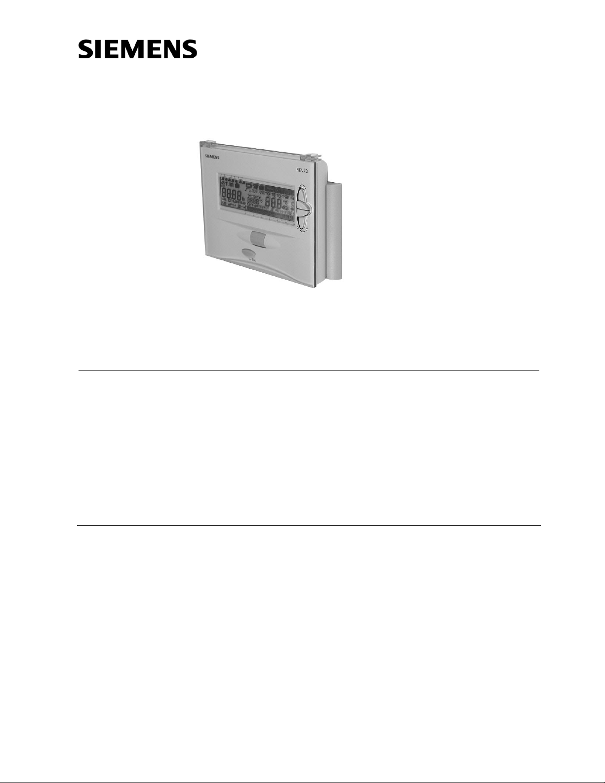
Self-learning Room
Temperature Controller
REV23
5 operating modes, heating / cooling functions and menu selection via roller selector
• Mains-independent room temperature controller
• Straightforward, self-explanatory menu selection via roller selector
• Self-learning 2-position controller providing PID mode (patented)
• Choice of operating modes:
automatic with maximum 3 heating or cooling periods, continuously comfort
mode, continuously economy mode, frost protection with one 24-hour operating mode and one heating or cooling period
• In automatic mode, one temperature setpoint can be adjusted for each heating
or cooling period
• Control of cooling equipment
Use
For the control of the room temperature in:
• Apartments, single-family or holiday houses
• Offices, individual rooms, consulting rooms or commercially used spaces
For control of the following pieces of equipment:
• Solenoid valves of instantaneous water heaters
• Solenoid valves of atmospheric gas burners
• Forced draft gas or oil burners
• Circulating pumps in heating systems, zone valves
• Electric direct heating systems or fans of electric storage heaters
• Thermic actuators
• Cooling and refrigeration equipment
Page 2
2/12
Siemens Building Technologies Room Temperature Controller REV23 CE1N2264en
HVAC Products 23.04.2002
Functions
• PID mode with self-learning or selectable switching cycle
• 2-position control
• Automatic mode with 7-day switching program for 24-hour, working day, weekend or
7-day operation with up to 3 heating or cooling periods per day
• One temperature setpoint for each heating or cooling period
• One 24-hour operating mode with one heating or cooling period
• Remote operation
• Override button
• Sensor calibration and reset function
• Frost protection function or overtemperature protection
• Limitation of the minimum setpoint
• Holiday mode
• Heating or cooling mode
• Periodic pump run
• Optimum start control for the first heating period
Ordering
Room temperature controller with 7-day time switch REV23
When ordering, please give the type reference.
The controller is supplied complete with batteries.
Technical design
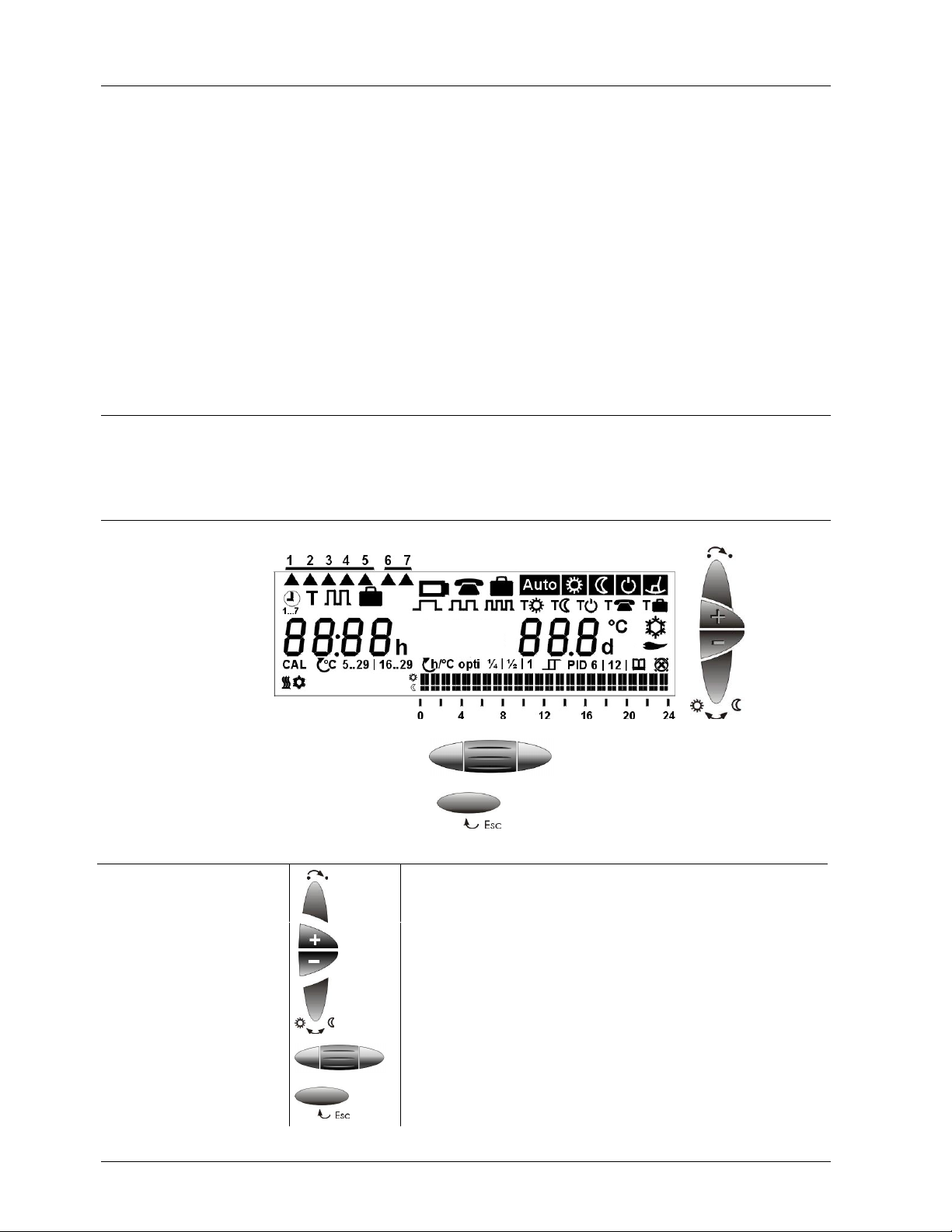
Display and
operating elements
Operating elements
Selection of operating mode
Warmer button
Colder button
Override button
Roller selector for the menu, submenu and settings
Confirm by pressing
Leaving the current menu level and returning to the menu level
previously active (the settings currently displayed will be accepted)
Page 3
3/12
Siemens Building Technologies Room Temperature Controller REV23 CE1N2264en
HVAC Products 23.04.2002
Display
Time of day
° C
Room temperature
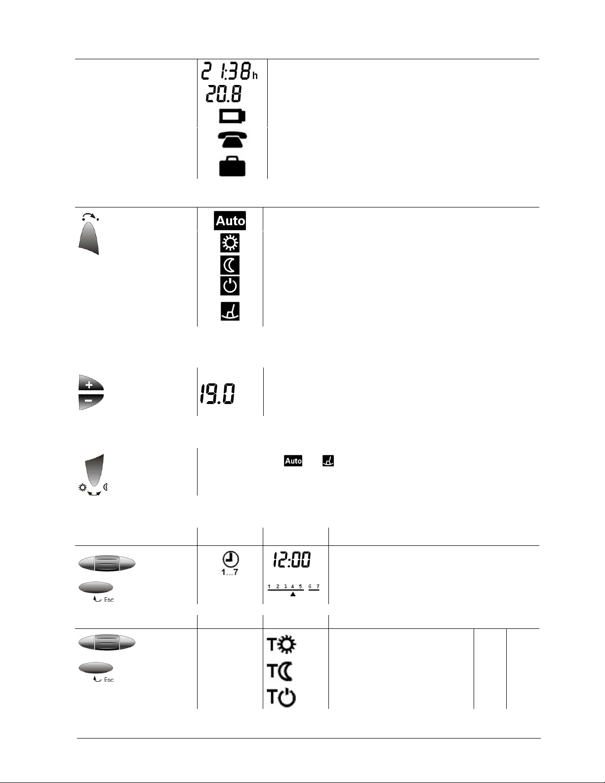
Change batteries (display appears about 3 months before batteries are exhausted)
Remote operation active
Holiday mode active
Selection of operating mode (only one operating mode is activ)
Automatic mode
Comfort mode
Economy mode
Frost protection or overtemperature protection
24-hour mode with one heating or cooling period
(heating or cooling period is automatically generated from the
current 24-hour program)
Temporary change of the current setpoint temperature
(change only active until the next switching point is reached)
° C
When pressing the + or – button once, the adjusted setpoint
temperature will be displayed. It can be readjusted in increments of 0.2 °C (max. +/- 4 °C).
Override button
In operating modes and , this button can be used to switch from comfort
to economy temperature, or vice versa. The selection is maintained until the
next switching point is reached or until the operating mode is changed.
Menu-driven user settings: 4 main menus available
Time of day and day
Main menu Submenu Settings
h
Current time of day
Current day of week
Temperature Main menu Submenu
Factory settings – heating / cooling
T
Setpoint comfort mode 19 °C 23 °C
Setpoint economy mode 16 °C 29 °C
Setpoint frost
or overtemperature protection
5 °C 35 °C
Page 4
4/12
Siemens Building Technologies Room Temperature Controller REV23 CE1N2264en
HVAC Products 23.04.2002
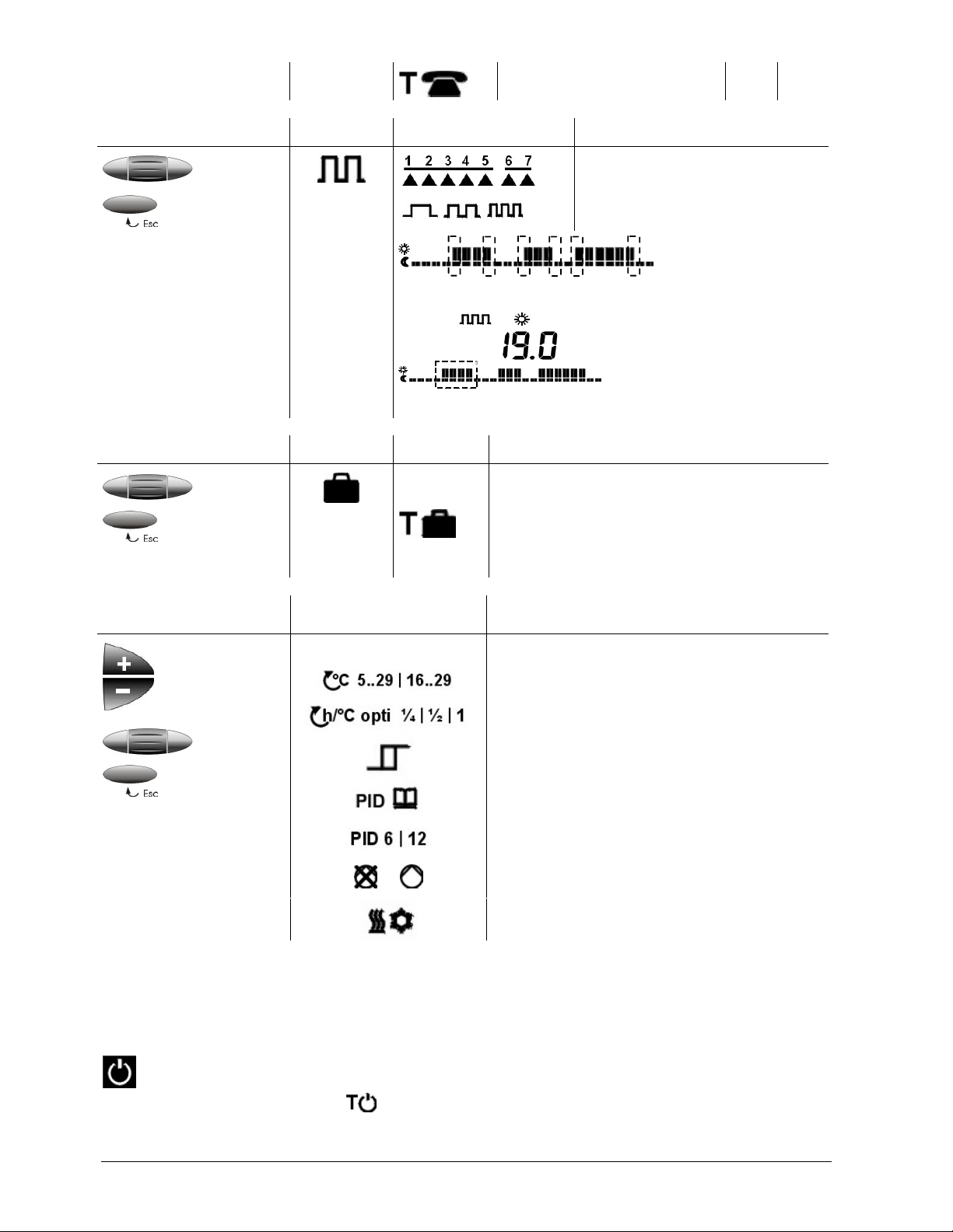
Setpoint economy mode
remote operation
10 °C 30 °C
Time switch
Main menu Submenu Settings
Selection of day of week, working
day, weekend or week
Selection of the number of heating
or cooling periods, max. 3
Selection of heating / cooling period start and end time
° C
T
Selection of heating / cooling period setpoint temperature
Absence
Main menu Submenu
Entry of holidays or periods of absence.
(number of days with economy mode setting /
max. 99 days)
Temperature setpoint during absence
Factory setting 12 °C
Menu-driven heating
engineer settings
Main menu Settings
CAL
Sensor calibration
Setpoint limitation
Optimum start control for first heating period
(in unit of time per 1 °C)
2-position control
PID mode, self-learning
PID mode with a switching cycle of 6 or
12 minutes
/
Periodic pump run Off / On
Operating mode heating / cooling
In the automatic operating modes, temperature setpoints can be individually adjusted
for every comfort period and for the continuous operating modes. The temperature
setpoint of economy mode is the same in automatic and continuous operation.
In the frost or overtemperature protection mode, the room temperature is constantly
monitored. If it falls (rises) below (above) the adjusted setpoint, heating / cooling is
switched on to maintain the adjusted frost or overtemperature protection setpoint tem-
perature
.
Temperature
setpoints
Protective function
Page 5
5/12
Siemens Building Technologies Room Temperature Controller REV23 CE1N2264en
HVAC Products 23.04.2002
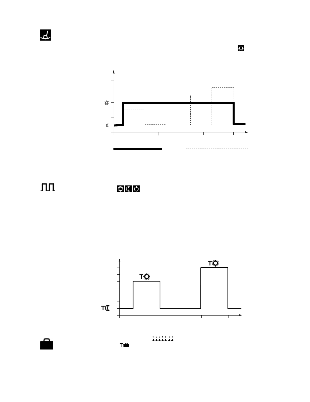
The controller generates the 24-hour operating mode from the current 24-hour program. It automatically selects the switch-on time of the first heating / cooling period and
the switch-off time of the last heating / cooling period to generate and display a complete heating / cooling period. The comfort temperature used by the controller is the
currently stored standard setpoint of the continuous operating mode
. The selfgenerated 24-hour operating mode is maintained until another operating mode is selected.
2264Z01
°C
18
20
22
08 10 18 22
h
T
T
Automatically generated Current 24-hour switching program
24-hour operating mode
The switching program can be used as a 7-day or 24-hour switching program,
depending on programming. It is also possible to select one of the continuous operating
modes
with which the switching program is not used.
With the 7-day switching program, it is possible to program all days individually, the
working days (1-5), the weekend (6-7), or the entire week (1-7).
When a heating / cooling period is programmed, 3 different switching patterns are
available.
It is possible to select 1, 2 or 3 heating / cooling periods.
For each heating / cooling period, the start time, end time and comfort setpoint are to
be entered. In between heating / cooling periods, it is always the same economy temperature setpoint that is used. This economy temperature setpoint can be adjusted on
the temperature menu.
2261Z04
16
°C
18
20
22
08 10 18 22
h
Heating
period 1
Heating
period 2
The holiday function is to be selected on the user menu. Set the start of the holiday
period (day of departure/
/ day of week), the duration and the temperature
setpoint (
) during your absence. This will enable the controller to maintain the required temperature for a period of up to 99 days. Every midnight, the counter subtracts
one day.
24-hour operating mode
Example
Switching program
Example with 2 heating
periods per day
Holiday function
Page 6

6/12
Siemens Building Technologies Room Temperature Controller REV23 CE1N2264en
HVAC Products 23.04.2002
When the holiday period is over and the counter reads 00, the controller will resume the
operating mode selected last.
Using a suitable remote operating device, the controller can be switched to an independently adjustable economy temperature
. Changeover is accomplished by the
making of a potentialfree contact connected to terminals T1 and T2. In that case, symbol
will appear on the display. When the contact opens, the operating mode se-
lected last will be resumed.
Operation according to the setting made on
the controller
Continuously remote operation economy
temperature
T2
T1
2252Z05
T2
T1
2252Z06
Suitable remote operating devices:
telephone modem, manual switch, window switch, presence detector, central unit, etc.
Switching times Temperatures in ° C
1
st
period
2
nd
period
3
rd
period
Oper-
ating
mode
Block /
week-
days
1st period 2nd period 3rd period
Auto
1-5
Mo-Fr
6-7
Sa-Su
06.00
07.00
08.00
23.00
11.00 13.00 17.00 22.00
1919232320 23 21 23 161629
29
1-7
Mo-Su
00.00 24.00
19 23
1-7
Mo-Su
00.00 24.00
16 29
1-7
Mo-Su
00.00 24.00
5 35
10 30
Absence 12 30
Setpoint limitation
PID mode, self-learning
Optimum start control
Periodic pump run Off
Heating active
Remote operation
Remote operating
devices
Factory settings
Factory settings
heating engineer level
Page 7

7/12
Siemens Building Technologies Room Temperature Controller REV23 CE1N2264en
HVAC Products 23.04.2002
Heating engineer level
To access the heating engineer level, keep the warmer and colder buttons depressed
and simultaneously roll the roller selector away from the display and then toward the
display.
If the displayed temperature does not correspond to the effective room temperature, the
temperature sensor can be recalibrated (recalibration to be made on the heating engineer level).
The displayed temperature can be matched to the effective room temperature in increments of 0.2 °C (max. ±2 °C).
Minimum setpoint limitation of 16 °C prevents undesired heat transfer to neighboring
apartments in buildings with several heating zones. The setting is to be made on the
heating engineer menu.
Optimization brings forward the switch-on point of the first heating period such that the
adjusted setpoint will be reached at the desired time.
The setting depends on the type of controlled system, that is, on heat transmission
(type of piping system, radiators), building dynamics (building mass, insulation), and
heat output (boiler capacity, flow temperature).
Optimum start control is switched off at
t
T
17
18
19
- 4
- 2
2264D03
16
- 3
1/4h/°C
1/2h/°C
1h/°C
Start
- 2
- 1
- ½
- 1½
- 1
- ½
- ¼
- ¾
P
on
20
°C
- 1
h
h
h
TR
x
h
h
h
h
h
h
h
h
h
1st heating period
(slow controlled system)
(medium controlled system)
(fast controlled system)
(no impact)
Optimum start controll Off
T
T Temperature (°C) TRxActual value of room temperature
t Forward shift of switch-on point (h) P
on
Starting point of optimum start control
The REV23 is a 2-position controller providing PID mode. The room temperature is
controlled through the cycling switching of an actuating device.
The controller generates the positioning signals depending on the deviation of the adjustable setpoint from the actual value acquired by the built-in temperature sensor.
The rate of response to the deviation depends on the selected control algorithm:
The controller is supplied with an active self-learning operating mode, enabling it to
automatically adapt to the controlled system (type of building construction, type of radiators, size of the rooms, etc.). After a certain learning period, the controller optimizes
its parameters and then operates with the learned parameters.
In exceptional cases, in which the self-learning mode may not be ideal, it is possible to
select PID 12, PID 6 or 2-Pt mode:
Accessing
Sensor calibration
CAL
Limitation of setpoint
Optimum start control
Example with an actual room temperature
of 18 °C and a setpoint
of
20 °C:
Control
Self-learning mode
Exceptions
Page 8

8/12
Siemens Building Technologies Room Temperature Controller REV23 CE1N2264en
HVAC Products 23.04.2002
PID 12 mode Switching cycle of 12 minutes for normal or slow controlled systems
(massive building structures, large spaces, cast-iron radiators, oil
burners).
PID 6 mode Switching cycle of 6 minutes for fast controlled systems (light building
structures, small spaces, plate radiators or convectors, gas burners).
2-Pt mode Pure 2-position control with a switching differential of 0.5 °C (±0.25 °C)
for very difficult controlled systems with considerable outdoor temperature variations.
Protects the pump against seizing during longer off periods. Periodic pump run is activated for one minute every 24 hours at midnight. This function can be selected on the
heating engineer menu.
Periodic pump run active:
/ periodic pump run inactive:
The controller is suited for cooling applications.
The function can be selected on the heating engineer menu.
The controller comes set for heating operation (refer to factory settings).
User-defined data:
Press the button behind the pin opening for at least one second: this resets the userspecific settings to their default values (the heating engineer settings will not be
changed). The clock starts at 12:00. During the reset time, all sections of the display
light up, enabling them to be checked.
All user-defined data plus the heating engineer settings:
Press the button behind the pin opening together with the warmer and colder buttons
for at least one second.
After this reset, all factory settings will be reloaded (also refer to section “Factory settings“).
Mechanical design
About 3 months before the batteries are exhausted, the battery symbol appears
on the display, but all functions will be fully maintained. When changing the batteries,
the current data will be retained for a maximum of one minute.
The REV23 has a plastic housing with a large display and easily accessible operating
elements. The controller is removed from its base by sliding it upward. It is thus possible to replace the two 1.5 V alkaline batteries type AA in the compartment at the rear of
the controller.
The base can be fitted to most types of commercially available recessed conduit boxes
or directly on the wall for wiring. The base only houses the terminals for the electrical
connection between the controller and connected devices. The entire electronics (including the relay with a potentialfree changeover contact) are accommodated in the
controller.
Periodic pump run
/
Operating mode
heating / cooling
/
Reset functions
Battery change
Controller
Base
Page 9

9/12
Siemens Building Technologies Room Temperature Controller REV23 CE1N2264en
HVAC Products 23.04.2002
Notes
• The room temperature controller should be fitted in the main living room
• The place of installation should be chosen such that the sensor can capture the room
temperature as accurately as possible, without being affected by direct solar radiation or other heating or cooling sources
• Mounting height is approximately 1.5 m above the floor
• The controller can be fitted to most commercially available recessed conduit boxes or
directly on the wall
• Above the unit, there must be sufficient clearance for removing the controller from its
base and for replacing it
min.
10 cm
2261Z03
• When installing the controller, the base must first be fitted and wired. Then, the unit
can be slid onto the base from above
• For more detailed information, please refer to the installation instructions supplied
with the controller
• For the electrical installation, the local safety regulations must be complied with
• The remote operation contact T1 / T2 must be wired separately using a separate
screened cable
• The battery transit tab, which prevents inadvertent operation of the controller during
transport and storage, must be removed
• The control mode can be changed on the heating engineer level
• If the reference room is equipped with thermostatic radiator valves, they must be set
to their fully open position
• If the displayed room temperature does not correspond to the effective room temperature, the temperature sensor should be recalibrated
(refer to “Sensor calibration”)
Engineering
Mounting and
installation
Commissioning
Page 10

10/12
Siemens Building Technologies Room Temperature Controller REV23 CE1N2264en
HVAC Products 23.04.2002
Technical data
Operating voltage
Batteries (alkaline AA)
Battery life
Backup for batter change
DC 3 V
2 x 1.5 V
approx. 2 years
max. 1 min
Switching capacity of relay
Voltage
Current
AC 24…250 V
6 (2.5) A
Safety class II to EN 60 730-1
Sensing element
Measuring range
Time constant
NTC 10 kΩ ±1 % at 25 °C
0…50 °C
max. 10 min
Setpoint setting ranges
Normal temperature
Economy temperature
Frost protection temperature
5…29 °C
5…29 °C
5...29 °C (factory setting 5 °C)
Resolution of settings and display
Setpoints
Switching times
Measurement of actual value
Display of actual value
Display of time
0.2 °C
10 min
0.1 °C
0.2 °C
1 min
CE conformity
Electromagnetic compatibility
Low voltage directive
89/336/EEC
73/23/EEC
C-Tick
N474
Automatic electrical controls for household
and similar use EN 60 730-1
Electromagnetic compatibility
Immunity
Emissions
EN 50082-1
EN 50081-1
Operation
Climatic conditions
Perm. ambient temperature
Humidity
class 3K3 to IEC 60 721-3
5...40 °C
< 85 % r.h.
Storage and transport
Climatic conditions
Ambient temperature
Humidity
Mechanism
class 2K3 to IEC 60 721-3
-25…+70 °C
< 93 % r.h.
class 2M2 to IEC 60 721-3
Incl. package 0.33 kg
Housing signal-white RAL9003
Base grey RAL7038
Housing 140 x 104.5 x 30 mm
General unit data
Norms and standards
Product standards
Environmental
conditions
Weight
Color
Size
Page 11

11/12
Siemens Building Technologies Room Temperature Controller REV23 CE1N2264en
HVAC Products 23.04.2002
Connection diagram
L
L1
Y1
M1
N1
A
C
2
4
.
.
.
2
5
0
V
2
2
5
2
A
0
2
N
S1
T1 T2
L2
L
N
DC 3 V
L Live AC 24…250 V N1 Room temperature controller REV23
L1 N.O. contact, AC 24…250 V / 6 (2.5) A S1 Remote operating device (potentialfree)
L2 N.C. contact, AC 24…250 V / 6 (2.5) A T1 Signal “remote operation”
M1 Circulating pump T2 Signal “remote operation”
N Neutral conductor Y1 Actuating device
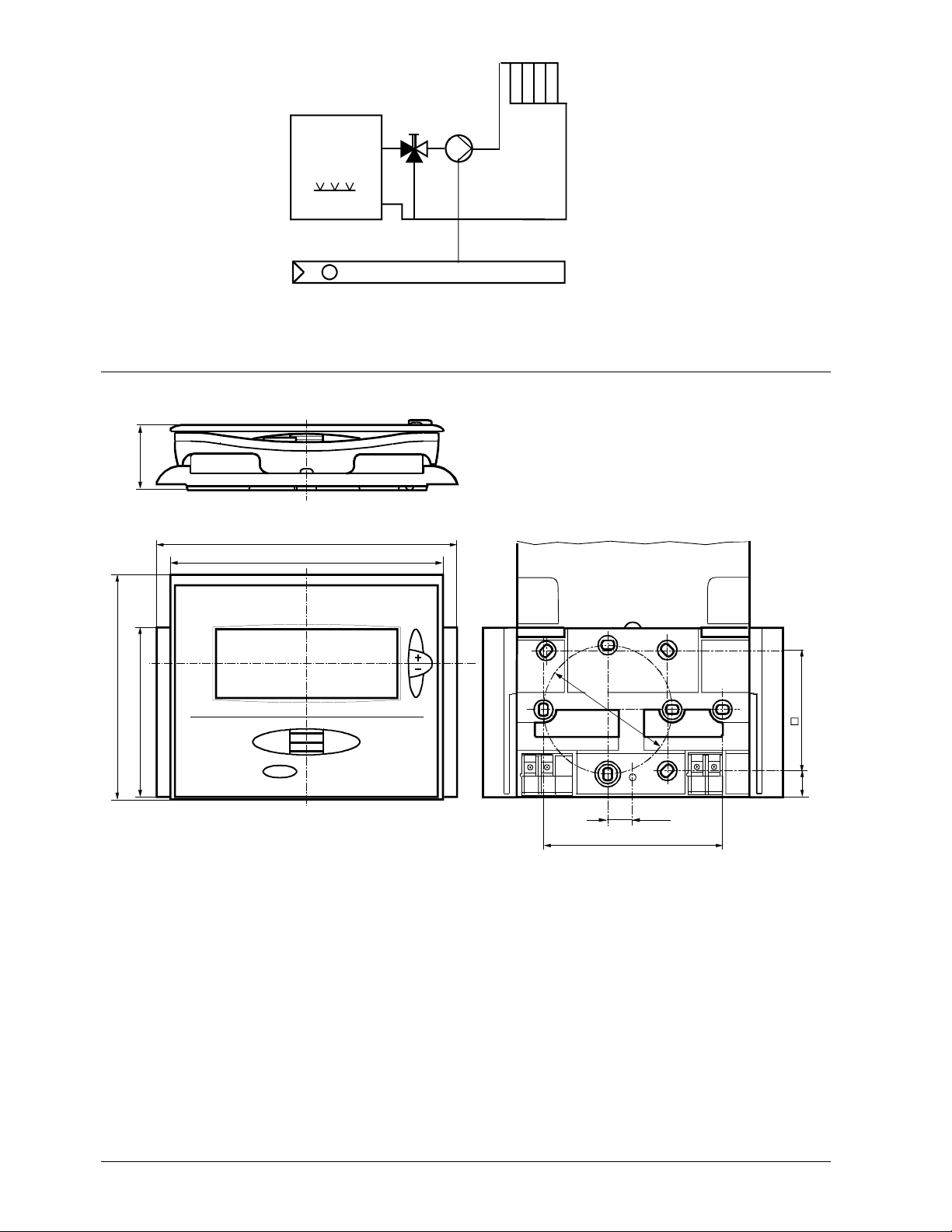
Application examples
F2
F1
Y2
T
T
M1
N1
T
2261S03
T
F1
F2
N1
M1
Y2
2261S01
T T
Instantaneous water heater Atmospheric gas burner
2261S02
M M
Y3
N1
T
N1
T
Y4
T
N1
2264S01
E1
Zone valve Cooling equipment
Page 12
12/12
Siemens Building Technologies Room Temperature Controller REV23 CE1N2264en
HVAC Products 23.04.2002
E1 Cooling equipment
F1 Limit thermostat
F2 Safety limit thermostat
M1 Circulating pump
N1 Room temperature controller REV23
Y1 3-port valve with manual adjustment
Y2 Solenoid valve
Y3 Motorized 3-port valve
Y1
2261S04
M1
T
N1
Y4 Motorized 2-port valve
Circulating pump with precontrol via manual mixing valve
Dimensions
127
140
78.8
104.5
83.50
56
12
11.75
2264M01
30
Ø
6
0
ã2001 Siemens Building Technologies AG Subject to alteration
 Loading...