

Page 1

SIMATIC Industrial PC SIMATIC Panel PC 877
DOCUMENTATION
Operating Instructions Edition 07/2006
Industrial PC
Panel PC 877
simatic
DOCUMENTATION
Page 2

Page 3

SIMATIC
Industrial PC
SIMATIC Panel PC 877
Operating instructions
Foreword
Safety information
Description
Application planning
Installation
Connecting
Integration into an
automation system
Commissioning
1
2
3
4
5
6
7
8
Operation and configuration
Operation
Functions
Maintenance and service
Alarm, error and system
messages
Troubleshooting/FAQs
Technical data
Dimension drawings
9
10
11
12
13
14
15
16
Release 07/2006
A5E00877780-01
Detailed descriptions
Appendix
ESD directives
List of
abbreviations / acronyms
17
A
B
C
Page 4
Safety Guidelines
This manual contains notices you have to observe in order to ensure your personal safety, as well as to prevent
damage to property. The notices referring to your personal safety are highlighted in the manual by a safety alert
symbol, notices referring only to property damage have no safety alert symbol. These notices shown below are
graded according to the degree of danger.
Danger
indicates that death or severe personal injury will result if proper precautions are not taken.
Warning
indicates that death or severe personal injury may result if proper precautions are not taken.
Caution
with a safety alert symbol, indicates that minor personal injury can result if proper precautions are not taken.
Caution
without a safety alert symbol, indicates that property damage can result if proper precautions are not taken.
Notice
indicates that an unintended result or situation can occur if the corresponding information is not taken into
account.
If more than one degree of danger is present, the warning notice representing the highest degree of danger will
be used. A notice warning of injury to persons with a safety alert symbol may also include a warning relating to
property damage.
Qualified Personnel
The device/system may only be set up and used in conjunction with this documentation. Commissioning and
operation of a device/system may only be performed by qualified personnel. Within the context of the safety notes
in this documentation qualified persons are defined as persons who are authorized to commission, ground and
label devices, systems and circuits in accordance with established safety practices and standards.
Prescribed Usage
Note the following:
Warning
This device may only be used for the applications described in the catalog or the technical description and only in
connection with devices or components from other manufacturers which have been approved or recommended by
Siemens. Correct, reliable operation of the product requires proper transport, storage, positioning and assembly
as well as careful operation and maintenance.
Trademarks
All names identified by ® are registered trademarks of the Siemens AG. The remaining trademarks in this
publication may be trademarks whose use by third parties for their own purposes could violate the rights of the
owner.
Disclaimer of Liability
We have reviewed the contents of this publication to ensure consistency with the hardware and software
described. Since variance cannot be precluded entirely, we cannot guarantee full consistency. However, the
information in this publication is reviewed regularly and any necessary corrections are included in subsequent
editions.
Siemens AG
Automation and Drives
Postfach 48 48
90437 NÜRNBERG
GERMANY
Order No.: A5E00877780-01
Edition 07/2006
Copyright © Siemens AG 2006.
Technical data subject to change
Page 5

Table of contents
1 Foreword ................................................................................................................................................ 1-1
1.1 Overview .................................................................................................................................... 1-1
2 Safety information................................................................................................................................... 2-3
2.1 Safety information ...................................................................................................................... 2-3
2.2 General information ................................................................................................................... 2-6
3 Description.............................................................................................................................................. 3-1
3.1 Design........................................................................................................................................ 3-1
3.2 Technical features...................................................................................................................... 3-3
3.3 Accessories................................................................................................................................ 3-5
4 Application planning................................................................................................................................ 4-1
4.1 Overview .................................................................................................................................... 4-1
4.2 Unpacking and checking the delivery ........................................................................................4-2
4.3 Device identification data........................................................................................................... 4-3
4.4 Mounting Positions and Fastening............................................................................................. 4-4
4.4.1 Installation guidelines................................................................................................................. 4-4
4.4.2 Permitted mounting positions..................................................................................................... 4-6
4.4.3 Type of fixation........................................................................................................................... 4-7
4.4.4 Protection against dust and water ............................................................................................. 4-8
4.5 Mounting cut-out ........................................................................................................................ 4-9
4.5.1 Preparing the mounting cut-out.................................................................................................. 4-9
4.5.2 Mounting depth of the device................................................................................................... 4-11
4.6 EMC directive........................................................................................................................... 4-12
5 Installation .............................................................................................................................................. 5-1
5.1 Securing the device with clamps................................................................................................ 5-1
5.2 Securing the device with screws................................................................................................ 5-3
6 Connecting ............................................................................................................................................. 6-1
6.1 Connection and operator control components........................................................................... 6-1
6.2 Connecting the 100 V to 240 V AC power supply...................................................................... 6-4
6.3 Connecting the 24 V DC power supply...................................................................................... 6-6
6.4 Connecting the equipotential bonding circuit............................................................................. 6-7
SIMATIC Panel PC 877
Operating instructions, Release 07/2006, A5E00877780-01
iii
Page 6

Table of contents
7 Integration into an automation system .................................................................................................... 7-1
7.1 Overview .................................................................................................................................... 7-1
7.2 Device in a SIMATIC S7 configuration.......................................................................................7-2
7.2.1 MPI/PROFIBUS-DP network...................................................................................................... 7-2
7.2.2 Connecting an S7 automation system .......................................................................................7-3
7.3 Networking via Industrial Ethernet ............................................................................................. 7-4
8 Commissioning ....................................................................................................................................... 8-1
8.1 Overview .................................................................................................................................... 8-1
8.2 Switch on the device .................................................................................................................. 8-2
8.3 Setting up the Microsoft Windows operating system ................................................................. 8-3
8.4 Installing applications and drivers .............................................................................................. 8-4
8.5 BIOS settings ............................................................................................................................. 8-9
8.6 Microsoft Windows operating system ...................................................................................... 8-10
8.6.1 Enables .................................................................................................................................... 8-10
8.6.2 Windows 2000 Professional..................................................................................................... 8-11
8.6.3 Windows XP Professional........................................................................................................ 8-12
8.7 USB.......................................................................................................................................... 8-13
9 Operation and configuration.................................................................................................................... 9-1
9.1 Normal operation........................................................................................................................ 9-1
9.1.1 Switch on the device .................................................................................................................. 9-1
9.1.2 Logging on to the operating system via the onscreen keyboard (OSK) .................................... 9-3
9.1.3 Switching off the device ............................................................................................................. 9-4
9.2 Additional Drivers and Applications ........................................................................................... 9-5
9.2.1 Overview .................................................................................................................................... 9-5
9.2.2 Calibrating the touch screen, UPDD.......................................................................................... 9-6
9.2.3 Enable/disable touch functionality.............................................................................................. 9-8
9.2.4 Windows Security Center (Windows XP Professional only) .................................................... 9-10
9.2.5 KeyTools (for key panel devices only) ...................................................................................
.. 9-12
9.2.6 Screen keyboard (for touch panel device only)........................................................................ 9-13
9.2.7 Setbrightness ........................................................................................................................... 9-14
9.2.8 CheckLanguageID ................................................................................................................... 9-15
9.2.9 Multilingual settings for the operating system.......................................................................... 9-16
9.2.10 DVD ROM/CD RW ................................................................................................................... 9-18
9.2.11 USB keyboard controller .......................................................................................................... 9-19
10 Operation.............................................................................................................................................. 10-1
10.1 Status displays ......................................................................................................................... 10-1
10.2 General control elements ......................................................................................................... 10-2
10.3 Device with key panel .............................................................................................................. 10-3
10.3.1 Using the keyboard .................................................................................................................. 10-4
10.3.2 Using the direct control key module....................................................................................... 10-10
10.3.3 Labelling function keys and softkeys ..................................................................................... 10-14
10.3.4 Using the integrated mouse ................................................................................................... 10-16
10.4 Device with touch screen ....................................................................................................... 10-17
10.4.1 Using the touch screen .......................................................................................................... 10-18
10.5 Disk drive................................................................................................................................ 10-19
10.6 Transferring authorizations .................................................................................................... 10-20
SIMATIC Panel PC 877
iv Operating instructions, Release 07/2006, A5E00877780-01
Page 7

Table of contents
11 Functions.............................................................................................................................................. 11-1
11.1 Overview .................................................................................................................................. 11-1
11.2 Safecard on Motherboard (SOM)............................................................................................. 11-2
11.3 Temperature monitoring........................................................................................................... 11-4
11.4 Watchdog (WD)........................................................................................................................ 11-5
11.5 Fan monitoring ......................................................................................................................... 11-6
12 Maintenance and service...................................................................................................................... 12-1
12.1 Servicing .................................................................................................................................. 12-1
12.2 Replacement parts................................................................................................................... 12-3
12.3 Separating the control unit from the computer unit.................................................................. 12-4
12.4 Installing and removing hardware components ....................................................................... 12-7
12.4.1 Repairs..................................................................................................................................... 12-7
12.4.2 Open the device....................................................................................................................... 12-8
12.4.3 Installing and removing memory modules ............................................................................. 12-10
12.4.4 Installing PCI / AT cards ........................................................................................................ 12-12
12.4.4.1 Notes on the modules ............................................................................................................ 12-12
12.4.4.2 Installing / removing expansion modules............................................................................... 12-13
12.4.4.3 Exchanging the RAID controller PCI card.............................................................................. 12-15
12.4.5 Disk drives.............................................................................................................................. 12-16
12.4.5.1 Options of installing disk drives.............................................................................................. 12-16
12.4.5.2 Installing / removing a drive bay ............................................................................................ 12-18
12.4.5.3 Removing and installing an optical drive ............................................................................... 12-21
12.4.5.4 Removing and installing a 3.5" hard disk............................................................................... 12-24
12.4.6 Replacing the backup battery ................................................................................................ 12-25
12.4.7 Removing/Installing the Power Supply .................................................................................. 12-27
12.5 Installing Software.................................................................................................................. 12-29
12.5.1 General installation procedure............................................................................................... 12-29
12.5.2 Setting up the partitions for Windows operating systems...................................................... 12-30
12.5.3 Compatibility of the Restore DVD .......................................................................................... 12-32
12.5.4 Restoring the factory state of the software using the Restore DVD ...................................... 12-33
12.5.5 Installing Microsoft Windows operating systems ..........
......................................................... 12-35
12.5.5.1 Operating system not installed............................................................................................... 12-35
12.5.5.2 Booting from the Recovery CD .............................................................................................. 12-36
12.5.5.3 Installing the Microsoft Windows operating system (not for RAID)........................................ 12-37
12.5.5.4 Installing the Microsoft Windows operating system (for RAID).............................................. 12-38
12.5.6 Installing individual drivers..................................................................................................... 12-39
12.5.7 Operation of two hard disks ................................................................................................... 12-40
12.5.7.1 2 HDD system........................................................................................................................ 12-40
12.5.7.2 RAID system with Promise Fast Track Controller TX2300.................................................... 12-41
12.5.7.3 Installing the RAID Controller software.................................................................................. 12-44
12.5.8 Installing burner and DVD software ....................................................................................... 12-45
12.5.9 Backing up the hard disk........................................................................................................ 12-46
13 Alarm, error and system messages ...................................................................................................... 13-1
13.1 Boot error messages................................................................................................................ 13-1
13.2 Introduction to the BIOS beep codes....................................................................................... 13-3
13.3 BIOS beep codes..................................................................................................................... 13-5
SIMATIC Panel PC 877
Operating instructions, Release 07/2006, A5E00877780-01
v
Page 8

Table of contents
14 Troubleshooting/FAQs.......................................................................................................................... 14-1
14.1 General problems..................................................................................................................... 14-1
14.2 Problems when Using Modules of Third-party Manufacturers................................................. 14-2
14.3 Temperature limits ................................................................................................................... 14-3
15 Technical data ...................................................................................................................................... 15-1
15.1 General technical data ............................................................................................................. 15-1
15.2 Power requirements of the components .................................................................................. 15-8
15.3 Device with AC voltage supply................................................................................................. 15-9
15.4 Device with DC voltage supply .............................................................................................. 15-10
15.5 Keyboard table ....................................................................................................................... 15-11
16 Dimension drawings ............................................................................................................................. 16-1
16.1 Panel PC 877 dimensional drawing ......................................................................................... 16-1
16.2 Dimensional drawings for the installation of expansion modules ............................................16-3
17 Detailed descriptions ............................................................................................................................ 17-1
17.1 Motherboard............................................................................................................................. 17-1
17.1.1 Structure and functions of the motherboard............................................................................. 17-1
17.1.2 Technical features of the motherboard .................................................................................... 17-2
17.1.3 Position of the ports on the motherboard................................................................................. 17-4
17.1.4 External interfaces ................................................................................................................... 17-5
17.1.5 Front interfaces ...................................................................................................................... 17-13
17.1.6 Internal interfaces................................................................................................................... 17-18
17.2 Bus board ............................................................................................................................... 17-24
17.2.1 Layout and principle of operation........................................................................................... 17-24
17.2.2 Assignment of the PCI IRQ channels to the PCI slots........................................................... 17-25
17.2.3 Exclusive PCI hardware interrupt........................................................................................... 17-26
17.2.4 ISA slot pin assignment.......................................................................................................... 17-27
17.3 Operating system licenses ..................................................................................................... 17-29
17.4 Cables .................................................................................................................................... 17-30
17.5 System resources .................................................................................................................. 17-31
17.5.1 Currently allocated system resources.................................................................................... 17-31
17.5.2 System resources used by the BIOS/DOS ............................................................................ 17-32
17.5.2.1 I/O address allocation ............................................................................................................ 17-32
17.5.2.2 Interrupt Assignments ............................................................................................................ 17-34
17.5.2.3 Memory address assignments ............................................................................................... 17-35
17.6 BIOS setup ............................................................................................................................. 17-36
17.6.1 Overview ................................................................................................................................ 17-36
17.6.2 Starting BIOS Setup............................................................................................................... 17-37
17.6.3 BIOS setup menus ................................................................................................................. 17-38
17.6.4 Main menu.............................................................................................................................. 17-40
17.6.5 Advanced menu ..................................................................................................................... 17-51
17.6.6 Security menu ........................................................................................................................ 17-59
17.6.7 Power menu ........................................................................................................................... 17-61
17.6.8 Boot menu.............................................................................................................................. 17-62
17.6.9 Version menu ......................................................................................................................... 17-64
17.6.10 Exit menu ............................................................................................................................... 17-65
17.6.11 BIOS setup default settings.................................................................................................... 17-66
SIMATIC Panel PC 877
vi Operating instructions, Release 07/2006, A5E00877780-01
Page 9

Table of contents
A Appendix.................................................................................................................................................A-1
A.1 Certificates and guidelines.........................................................................................................A-1
A.1.1 Guidelines and declarations....................................................................................................... A-1
A.1.2 Certificates and approvals ......................................................................................................... A-3
A.1.3 Electrostatic charging of individuals...........................................................................................A-5
A.2 Additional support ...................................................................................................................... A-6
B ESD directives........................................................................................................................................B-1
B.1 ESD guideline ............................................................................................................................ B-1
C List of abbreviations / acronyms .............................................................................................................C-1
C.1 Abbreviations .............................................................................................................................C-1
Glossary ..................................................................................................................................... Glossary-1
Index................................................................................................................................................ Index-1
Tables
Table 4-1 Dimensions for the mounting cut-out in mm ............................................................................ 4-10
Table 10-1 Keyboard codes ..................................................................................................................... 10-11
Table 13-1 Converting the beep codes in a Hex display ........................................................................... 13-3
Table 16-1 Panel PC 877 dimensions in mm............................................................................................. 16-2
SIMATIC Panel PC 877
Operating instructions, Release 07/2006, A5E00877780-01
vii
Page 10

Table of contents
SIMATIC Panel PC 877
viii Operating instructions, Release 07/2006, A5E00877780-01
Page 11

Foreword
1.1 1.1 Overview
Purpose of the manual
These operating instructions contain all the information you need for commissioning and
using the SIMATIC Panel PC 877.
It is intended both for programming and testing personnel who commission the device and
connect it with other units (automation systems, programming devices), as well as for service
and maintenance personnel who install add-ons or carry out fault/error analyses.
Required basic knowledge
A solid background in personal computers and Microsoft operating systems is required to
understand this manual. General knowledge in the field of automation control engineering is
recommended.
Scope of this manual
This manual applies to devices with the order numbers 6AV781.…
1
Approvals
For more information, please refer to the chapter "Certificates and Guidelines" in the
appendix.
CE marking
For more information, please refer to "Directives and Declarations" in the "Certificates and
Guidelines" section of the appendix.
Standards
Please refer to sections "Application planning" and "Technical data".
SIMATIC Panel PC 877
Operating instructions, Release 07/2006, A5E00877780-01
1-1
Page 12
Foreword
1.1 Overview
Position in the information landscape
The documentation for the Panel PC includes the following sections:
• SIMATIC Panel PC 877, Operating Instructions (compact) with the following information:
– Commissioning
– Legal information
• SIMATIC Panel PC 877, Operating Instructions
The documentation is supplied with the Panel PC in electronic form as a PDF file on the
"Documentation and Drivers" CD. The documentation is available in German, English,
French, Italian and Spanish.
Additional information about the Windows operating system is available on the Internet at the
Microsoft homepage at http://www.Microsoft.com.
Conventions
The following text notation will facilitate reading this manual:
Representation Validity
"File"
"File > Edit" Operational sequences, e.g., menu commands/shortcut menu
<F1>, <Shift>+<F1> Keys and key combinations
• Terminology that occurs in the user interface, e.g., dialog
names, tabs, buttons, menu commands
• Required parameters such as limit values, tag values
• Path information
commands.
Trademarks
The term "Panel PC 877", "control unit" and "computer unit" is uniformly referred to as the
"device" in these operating instructions. The full term is only used when a concrete reference
is necessary.
Note
A note is important information about the product, handling the product or a reference to
specific sections of the documentation that require special consideration.
All names labeled with ® symbol are registered trademarks of Siemens AG. Other names
used in this documentation may be trademarks, the use of which by third parties for their
own purposes could violate the rights of the owner.
HMI®
SIMATIC®
SIMATIC HMI®
SIMATIC WinCC®
SIMATIC WinCC flexible®
Panel PC 877®
SIMATIC Panel PC 877
1-2 Operating instructions, Release 07/2006, A5E00877780-01
Page 13
Foreword
2.1 Safety information
Safety information
2.1 2.1 Safety information
Warning
Emergencies
In the event of a device fault, interrupt the power supply immediately. Inform the customer
service personnel responsible. Malfunctions can occur when the operator controls or power
cable are damaged or when liquids or foreign objects penetrate the device.
Warning
Following the results of a risk analysis, additional protection equipment on the machine or
the system is necessary to avoid endangering persons. With this, especially the
programming, configuration and wiring of the inserted I/O modules have to be executed, in
accordance with the necessary risk analysis identified safety performance (SIL, PL or Cat.).
The intended use of the device has to be ensured.
2
The proper use of the device has to be verified with a function test on the system. With this
programming, configuration and wiring errors can be identified. The test results have to be
documented and if necessary inserted into the relevant inputs.
Note
This device corresponds to the regulations of the EU low-voltage directive and the GPSG,
verified by conformity with national and international standards (DIN EN, IEC) by a UL
approval (cULuc). Please comply with all the information in these operating instructions
when assembling the device.
SIMATIC Panel PC 877
Operating instructions, Release 07/2006, A5E00877780-01
2-3
Page 14

Foreword
2.1 Safety information
Electrical connection
Warning
Disconnect the device from the mains before every intervention.
Do not touch power lines or data transmission lines during electrical storms and do not
connect any cables.
System expansions
Only install system expansion devices designed for this device. If you install other
expansions, you may damage the system or violate the safety requirements and regulations
for radio frequency interference suppression. Contact your technical support team or where
you purchased your PC to find out which system expansion devices may safely be installed.
Caution
If you install or exchange system expansions and damage your device, the warranty
becomes void.
High frequency radiation
Caution
Unintentional operating situations
High frequency radiation, e.g. from cell phones, can cause unintentional operating situations
under some circumstances. Further information is available in the section "EMC
requirements" of the "Technical data" chapter.
SIMATIC Panel PC 877
2-4 Operating instructions, Release 07/2006, A5E00877780-01
Page 15
Foreword
2.1 Safety information
Handling and disposal of lithium batteries
Warning
Danger of explosion and the release of harmful substances!
Do not throw lithium batteries into fire, do not solder onto the cell body, do not open, do not
short circuit, do not reverse pole, do not heat above 100 °C, dispose of according to
regulations, and protect from direct sunlight, moisture and condensation.
Replace lithium batteries with the same brand or a brand recommended by the
manufacturer.
Dispose of used lithium batteries as hazardous waste, individually, in accordance with the
local regulations.
Repairs
Only authorized personnel are permitted to repair the device.
Warning
Unauthorized opening of and improper repairs to the device may result in substantial
damage to equipment or endanger the user.
SIMATIC Panel PC 877
Operating instructions, Release 07/2006, A5E00877780-01
2-5
Page 16

Foreword
2.2 General information
2.2 2.2 General information
Overview
Transport
Caution
The device is approved for operation in closed rooms only. The guarantee is void if this
stipulation is ignored.
Avoid extreme environmental operating conditions. Protect your device against dust,
moisture and heat. For additional information, refer to the Technical data.
Do not place the device in direct sunlight.
Unpack the device at its installation location. Transport the device only in the original
packaging. Do not transport the device when it is mounted.
Notice
Adhere to these stipulations each time the device is transported, otherwise the guarantee is
void.
Caution
Condensation
When transporting the device at low temperatures, ensure that no moisture gets on or into
the device. This also applies if the device is subjected to extreme changes in temperature.
Commissioning
Allow the device to slowly adjust to room temperature before commissioning the device. Do
no place the device near heat radiation. If moisture condensation occurs, wait at least 12
hours before you switch on the device.
Vibration
Optical drives are sensitive to vibration. Inadmissible vibration during operation may result in
loss of data or damage to the drive or data medium.
Before transporting the device, wait at least 20 seconds to allow the drive to stop completely.
SIMATIC Panel PC 877
2-6 Operating instructions, Release 07/2006, A5E00877780-01
Page 17
Foreword
2.2 General information
Tools & downloads
Please check regularly if updates and hotfixes are available for download to your device.
Downloads are available on the Internet at http://www.siemens.com/asis under "Support".
Click on "Software Tools & Downloads" on "Overview Panel PCs" Using the global search
function, you can then also search for any downloads you require.
Processor and optical drive
Notice
An optical drive should only be operated in a mechanically undisturbed environment without
vibrations and shock.
Safety-relevant applications
Warning
Maloperation
Do not perform safety-relevant functions of the user software with the touch screen.
Chemical stability
Caution
Adhere to the information regarding chemical resistance of the panel front. Please go to
http://www.siemens.com/asis under "Tools & Downloads" for more information. Enter the
article ID 16532108 as the search term. The available articles are displayed.
SIMATIC Panel PC 877
Operating instructions, Release 07/2006, A5E00877780-01
2-7
Page 18

Foreword
2.2 General information
Sources of light
Notice
Position the screen so that it is not subject to direct sunlight or other strong sources of light.
Defective pixels in the display
At present, the manufacturing process of modern displays does not guarantee that all pixels
of the display will be perfect. A small number of defective pixels in the display is therefore
unavoidable. This does not present a functional problem as long as the defective pixels are
not bunched in one location.
Further information is available in the section "General technical data" of the "Technical
data" chapter.
Burn-in dffect on TFT displays
A permanent picture with bright images can lead to a burn-in effect on the TFT LCD.
If a screen saver is activated, please observe the following:
• The liquid crystals in screen savers which actuate active black when the backlighting is
on, e.g. flying stars "starfield simulation," renew themselves. Pay attention to the length of
time the backlighting is activated
• The following applies to screen savers which turn off the the backlighting: Each time the
backlighting is turned on, its life is reduced by 50 minutes.
Consider the following carefully:
• Screen saver
• Switch off the backlighting regularly
• Permanent display of the customer application
SIMATIC Panel PC 877
2-8 Operating instructions, Release 07/2006, A5E00877780-01
Page 19
Description
3.1 3.1 Design
Design
3
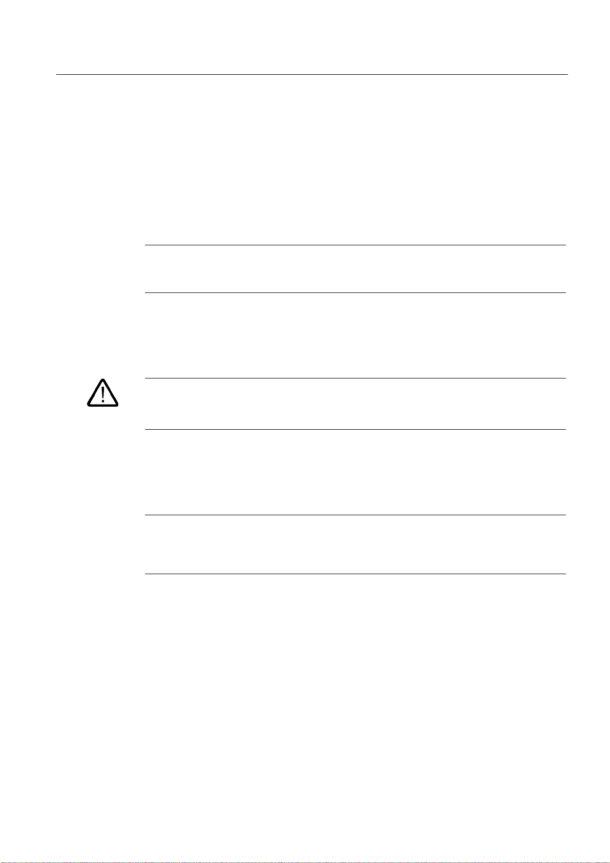
Figure 3-1 Panel PC 877
1 Computer unit
2 Control unit
Brief description
The device is available with different control units which are distinguished by the size of the
display and by the membrane keyboard or touch screen.
SIMATIC Panel PC 877
Operating instructions, Release 07/2006, A5E00877780-01
3-1
Page 20

Description
3.1 Design
Keyboard variants
• Color display with backlighting:
– 12'' TFT technology with 800 x 600 resolution
– 15'' TFT technology with 1024 x 768 resolution
• Membrane keyboard with alphanumeric keys, numeric keys, cursor keys and control keys
• Function keys and softkeys
• Integrated mouse
• LEDs for power supply, temperature, softkeys, <Shift> and <ACK> keys
• Front-mounted USB 2.0 interface for connecting external I/O devices. All fronts are also
available without USB interfaces accessible from the front.
Touch screen variants
• Color display with backlighting
– 15'' TFT technology with 1024 x 768 resolution
– 19'' TFT technology with 1280 x 1024 resolution
• LEDs for power supply and temperature
• Front-mounted USB 2.0 interface for connecting external I/O devices. All fronts are also
available without USB interfaces accessible from the front.
For additional information, refer to the Technical data.
SIMATIC Panel PC 877
3-2 Operating instructions, Release 07/2006, A5E00877780-01
Page 21

Description
3.2 Technical features
3.2 3.2 Technical features
General features
Slots for add-ons
Graphic VIA ProSavage 8
Disk drive Floppy disk drive
Interfaces
PROFIBUS/MPI 12 Mbps, electrically isolated, compatible to CP 5611
Ethernet 10/100 Mbit/s, RJ45
USB 2x USB 2.0, high current
Serial COM1 V.24, COM2 V.24
Parallel LPT1
Monitor 1 x DVI-I
Keyboard PS/2
Mouse PS/2
• 2x PCI long
• 2x PCI/ISA shared long
• 1x ISA long
• Note: The RAID1 option takes one PCI slot.
Graphics memory 8, 16 or 32 MB taken from main memory
CRT:
• up to 1600 x 1200 pixels, 60 Hz,16-bit color depth
• up to 1280 x 1024 pixels, 100 Hz,32-bit color depth
• LCD:
• LVDS or DVI up to 1280 x 1024 / 18-bit TFT
VGA monitors can be connected with a DVI/VGA adapter, to be
purchased separately.
SIMATIC Panel PC 877
Operating instructions, Release 07/2006, A5E00877780-01
3-3
Page 22

Description
3.2 Technical features
Configuration options
Power supply
Processor
Main memory 2-socket SDRAM DDR266: 256 MB, 512 MB, 1 GB, 2 GB
Hard disks
Disk drive
Operating system Without
• 100V/240V AC, 360 W; wide range; with bridgin
brief power failures in accordance with NAMUR:
maximum 20 ms at 0.85 x U
• 24 V DC, 265 VA, optional, only in connection with
Intel ® Pentium Mobile
• Intel ® Celeron 2 GHz,
400 MHz Front Side Bus FSB,
1024 Kbytes Second Level Cache
• Intel ® Pentium 4 2.8 GHz,
533 MHz Front Side Bus FSB,
512 Kbytes Second Level Cache
• Intel ® Pentium 4 Mobile 2.2 GHz,
400 MHz Front Side Bus FSB,
512 Kbytes Second Level Cache
• 1 x 3.5" hard disk ≥ 40 GB
• 1 x 3.5" hard disk ≥ 80 GB
• 2 x 2.5'' hard disks ≥ 60 GB with RAID 1 system SATA
• Without
• DVD-ROM
• CD-RW/DVD drive
Preinstalled, also provided on the Restore DVD and Microsoft
Recovery CD
• Windows 2000 Professional MUI*
• Windows XP Professional MUI*
*MUI: Multi-lingual user interface; German, English, French, Italian,
Spanish, Japanese, Korean, Chinese simplified and Chinese
traditional
(Un = rated voltage)
n
SIMATIC Panel PC 877
3-4 Operating instructions, Release 07/2006, A5E00877780-01
Page 23

Description
3.3 Accessories
3.3 3.3 Accessories
The accessories comprise the following components:
Accessories Comment Order No.
Direct control key module 6AV7671-7DA00-0AA0
Film for protecting the touch screen panel
against dirt and scratches
for 15" touch screen variant
for 19" touch screen variant
Film for labeling function keys
(slide-in labels)
DVI / VGA adapter A5E00254532
Backing plate for screw fixing of the 19" touch
front
Multi IO module Two parallel and two serial interfaces 6ES7648-2CA00-0AA0
SIMATIC PC DiagMonitor
software V 2.2
SIMATIC PC/PG Image & Partition Creator Software for local data backup 6ES7648-6AA03-0YX0
Module for DDR RAM memory expansion 256 MB
Remote Kit order version
Remote Kit, 24V DC, 5m
Remote Kit, 24V DC, 10m
Remote Kit, 24V DC, 20m
Remote Kit, 24V DC, 30m
Remote Kit, 120/230 V AC, 5m
Remote Kit, 120/230 V AC, 10m
Remote Kit, 120/230 V AC, 20m
Remote Kit, 120/230 V AC, 30m
1)
6AV7671-4BA00-0AA0
6AV7672-1CE00-0AA0
6AV7672-0DA00-0AA0
6AV7672-8KE00-0AA0
Software for monitoring local and remote
SIMATIC PCs:
• Watchdog
• Temperature
• Fan speed
• Hard disk monitoring, SMART
• System monitoring,
Ethernet monitoring: Heartbeat
Communication:
• Ethernet interface, SNMP protocol
• OPC for integrating in SIMATIC software
• Client server architecture
• Layout of log files
512 MB
1 GB
6ES7648-6CA02-2YX0
6ES7648-2AG20-0GA0
6ES7648-2AG30-0GA0
6ES7648-2AG40-0GA0
6AV7671-1EA00-5AA1
6AV7671-1EA01-0AA1
6AV7671-1EA02-0AA1
6AV7671-1EA03-0AA1
6AV7671-1EA10-5AA1
6AV7671-1EA11-0AA1
6AV7671-1EA12-0AA1
6AV7671-1EA13-0AA1
For further accessories, see Catalog or Siemens MALL
1) You can also find the print templates for the slide-in labels on the Internet
at:
http://www.siemens.com/asis
At
Tools & Downloads>Downloads>Produkt Support>Industrie-PC
8782947.
SIMATIC Panel PC 877
Operating instructions, Release 07/2006, A5E00877780-01
, enter the entry ID
3-5
Page 24

Description
3.3 Accessories
SIMATIC Panel PC 877
3-6 Operating instructions, Release 07/2006, A5E00877780-01
Page 25

Application planning
4.1 4.1 Overview
Introduction
This section describes the first steps after unpackaging, the permitted mounting positions
and the fixation. This section describes the necessary considerations for EMC.
Field of application
The Panel PC is an industry-standard PC platform for demanding tasks in the field of PCbased automation. The Panel PC is designed for on-site use on the machine, installed for
example in:
• Switchgear cabinet installation
• Swivel arm installation
• Rack installation
4
Note
In the following, the term "switchgear cabinet" also refers to rack, mounting rack,
switchboard, operator panel and console. The term "device" represents the Panel PC and
its variants.
SIMATIC Panel PC 877
Operating instructions, Release 07/2006, A5E00877780-01
4-1
Page 26

Application planning
4.2 Unpacking and checking the delivery
4.2 4.2 Unpacking and checking the delivery
Procedure
1. Please check the packaging material for transport damage upon delivery.
2. If any transport damage is present at the time of delivery, lodge a complaint at the
shipping company in charge. Have the shipper confirm the transport damage
immediately.
3. Unpack the device.
Caution
Do not lie the device on its back. This will avoid any damage to an optical drive which
may be present. Lie the front side on a soft surface to avoid damaging the front panel
USB port.
4. Keep the packaging material in case you have to transport the unit again.
Notice
The packaging protects the device during transport and storage. Therefore, never
dispose of the original packaging material!
5. Please keep the enclosed documentation in a safe place. You will need the
documentation when you start up the device for the first time.
6. Check the package contents for completeness and any visible transport damage. Check
for completeness using the enclosed scope of delivery list.
7. Should the contents of the package be incomplete or damaged, please inform the
responsible supply service immediately and fax us the enclosed form "SIMATIC IPC/PG
quality control report".
Warning
Make sure that a damaged device is not installed nor put into operation.
8. Note the identification information as described in the chapter "Identification data of the
device".
SIMATIC Panel PC 877
4-2 Operating instructions, Release 07/2006, A5E00877780-01
Page 27
Application planning
4.3 Device identification data
4.3 4.3 Device identification data
Procedure
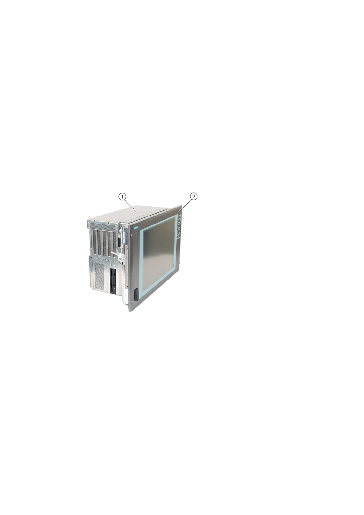
1. Write down the Microsoft Windows Product Key of the Certificate of Authenticity COA in
the table at the end of this section. The COA label is only present in preinstalled Windows
2000 Professional or XP Professional and is affixed to the back of the device. You will
need the product key during the reinstallation of the operating system.
Figure 4-1 COA label, example
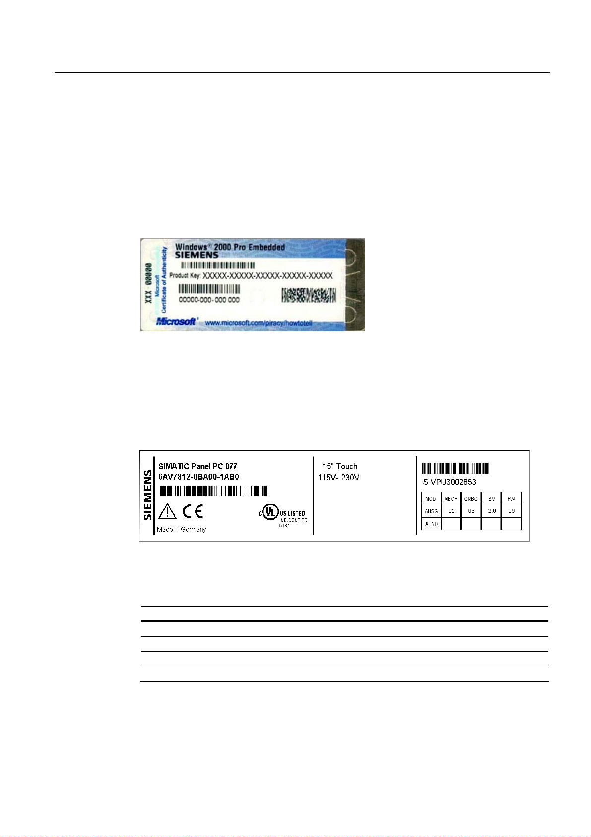
2. Write down the manufacturer's number SVP and the order number, for example "6AV...",
and enter it in the table. If repairs are necessary, the device can be identified by the
service center on the basis of the SVP number and order number.
Both numbers are located on the rating label on the computer unit at the top of the fan
side.
Figure 4-2 Panel PC 877 rating plate, example
3. Enter the Ethernet address of the device: The Ethernet address is located in the "Main"
menu of the BIOS setup, "Hardware Options > Ethernet Address."
Identification Number
1 Microsoft Windows Product Key COA
2 SVP number
3 Order number of the device
4 Ethernet address
SIMATIC Panel PC 877
Operating instructions, Release 07/2006, A5E00877780-01
4-3
Page 28

Application planning
4.4 Mounting Positions and Fastening
4.4 4.4 Mounting Positions and Fastening
4.4.1 Installation guidelines
Before installing the device, read the following general notes relating to installation.
Warning
Danger, high voltage
Isolate the power supply to the switchgear cabinet before opening it. Ensure that the power
to the switchgear cabinet cannot be turned on accidentally.
Caution
The device is approved for operation in closed rooms only.
• Ensure that the protective contact socket of the building installation is easily accessible
and that there is a mains disconnect switch in switchgear cabinet installations.
• Position the screen in an ergonomic position favorable to the user. Choose a suitable
installation height.
• Position the screen so that it is not subject to direct sunlight or other strong sources of
light.
• Optical drives are susceptible to shock. Shocks during operation can lead to the loss of
data or damage to the drive or data carrier. Optical drives are not only suitable for
continuous operation.
• Applies to devices which are installed in swivel arm housings: Avoid rapid or jerky
movements of the swivel arm during operation. The ensuing forces could lead to possible
irreversible damage of the hard disk.
The stops of the swivel arm must be damped in order to avoid any mechanical shock
effect to the Panel PC on attachment.
• Applies to devices which are installed in cabinet doors: Prevent the doors being slammed
shut. The ensuing forces could lead to possible irreversible damage of the hard disk.
• The device wtih DC power supply applies in the area of the computer unit and above all
the power supply connection in accordance with the UL approval as "open type" or "open
equipment". For this reason, the device must be installed in a control cabinet or housing
that complies with fire-proofing requirements
SIMATIC Panel PC 877
4-4 Operating instructions, Release 07/2006, A5E00877780-01
Page 29

Application planning
4.4 Mounting Positions and Fastening
Note
The computer unit with AC power supply satisfies fire protection requirements to
EN60950-1. It may therefore be installed without additional fire-proofing measures.
• Provide adequate volume in the switchgear cabinet for air circulation and heat transport.
Keep at least 10 cm distance between the device and switchgear cabinet.
• Ensure that the maximum air intake temperature, measured 10 cm before the air intake
opening on the fan, does not exceed 45°C. The maximum air intake temperature must be
accounted for especially when sizing closed switchgear cabinets.
• The minimum distance between the device and the housing is 10 cm on the air output
side at the fan.
• Position the device in such a way that the air vents of the housing are not covered up
following mounting.
• Ensure there is enough free space in the switchgear cabinet to allow the sheet metal
cover to be removed. You will otherwise have to remove the device from the switchgear
cabinet or swivel arm when replacing memory or the battery.
• Provide enough free space to add on to the device.
• Equip the switchgear cabinet with struts for stabilizing the mounting cut-out. Install struts
where necessary.
• Avoid extreme environmental operating conditions. Protect your device against dust,
moisture and heat.
• Install the device in such a way (see Chapter
danger, e.g. by falling over.
• During assembly, please comply with the approved installation positions.
Technical specifications
) that it poses no
Notice
If you mount the device in an impermissible installation position or you do not observe the
environmental conditions (see Chapter
product safety provided by the UL-approval and compliance with the low-voltage directive
(via EN 60950-1). In additional, the functionality of the device is no longer guaranteed.
Technical specifications
), you endanger the
For additional information, refer to the dimension diagrams in the appendix.
SIMATIC Panel PC 877
Operating instructions, Release 07/2006, A5E00877780-01
4-5
Page 30
Application planning
4.4 Mounting Positions and Fastening
4.4.2 Permitted mounting positions
Approval
Certain mounting positions are approved for the equipment that comprises one control unit
and one computer unit.
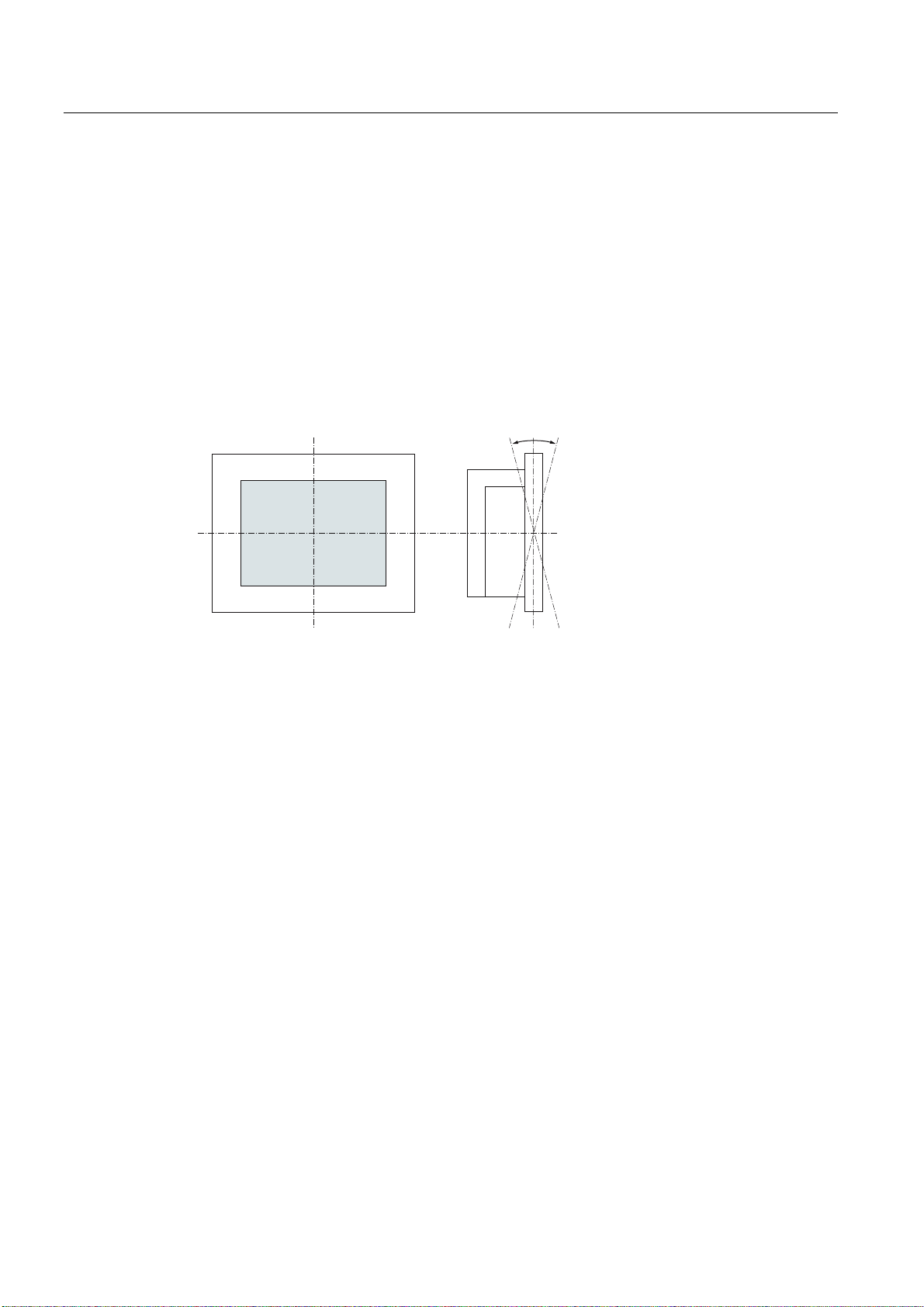
Permitted mounting positions
r
r
Vertical installation with deviations between +20° and -20° in the given directions is
permissible.
SIMATIC Panel PC 877
4-6 Operating instructions, Release 07/2006, A5E00877780-01
Page 31

Application planning
4.4 Mounting Positions and Fastening
4.4.3 Type of fixation
The computer unit is secured in the mounting cut-out either with clamps or screws.
Select the type of fixation suitable to your requirements for the degree of protection (see
Section
Protection against dust and water
) .
SIMATIC Panel PC 877
Operating instructions, Release 07/2006, A5E00877780-01
4-7
Page 32

Application planning
4.4 Mounting Positions and Fastening
4.4.4 Protection against dust and water
Principle
The degree of protection provided at the front is assured when the mounting seal lies
completely against the mounting cut-out.
Caution
Please ensure that the material strength at the mounting cut-out is a maximum of 6 mm.
Please follow the specifications for the dimensions in the "Mounting cut-out" section.
The degrees of protection are only guaranteed when the following is observed:
• The material strength at the mounting cut-out is at least 2 mm.
• The surface plane deviation of the mounting cut-out in relation to the external dimensions
of the control unit amounts to ≤ 0.5 mm when the control unit is mounted.
IP65 degree of protection and NEMA4
IP65 degree of protection and compliance with the NEMA4 regulations are only ensured
when clamp mounting together with a ring seal.
IP54 degree of protection
This degree of protection is achieved for screw fixing of all operator control units with a key
front panel and the 15" and 19" operator control units with a touch front panel. This degree of
protection is assured for the 19" operator control unit with a touch front panel when the
mounting components for 19" rack accessories are used.
Note
For screw fixing of the 19" touch panel front, a backing plate is available as an accessory.
For further information, see "http://mall.ad.siemens.com/
".
SIMATIC Panel PC 877
4-8 Operating instructions, Release 07/2006, A5E00877780-01
Page 33

Application planning
4.5 Mounting cut-out
4.5 4.5 Mounting cut-out
4.5.1 Preparing the mounting cut-out
The following illustration show the dimensions for the mounting cut-out.
$
$
6
/
/
/
/ /
/ 6 6 /
66
/ 6 6 /
/
/
/
/
Figure 4-3 Drill holes for the screws and pressure points for the clamp screws
/
PP
(1) Drill hole for screw attachment (4) Clamp
(2) Pressure points for clamp (5) R
(3) Setscrews (6) Seal area
Note
Installed dimensions can be read from the dimension overview or they can be transferred to
the cabinet from the mounting template supplied.
SIMATIC Panel PC 877
Operating instructions, Release 07/2006, A5E00877780-01
120 in the seal area
Z
4-9
Page 34

Application planning
4.5 Mounting cut-out
Table 4-1 Dimensions for the mounting cut-out in mm
Control unit L1 L2 L3
1)
L4
L5 L6
2)
L7
2)
L8
2)
L9
2)
A1 A2 S1 S2
S3
S5
3)
S6
S73)
3)
1)
S4
Tolerance +1 +1 ±0.2 ±0.5 ±0.5 ±0.5 ±0.5 +1 ±1 ±1 ±1 ±1 ±1 ±1
Key panel
12" TFT
15" TFT
Touch panel
15" TFT
19" TFT
450
290
465
235
112
450
321
465
279
112
450
290
465
235
112
450
380
465
235
112
1)
M6 thread or drilled holes of 7 mm diameter
2)
Cut-outs for the slots or inserted labels are required for 15'' key panels only
3)
Two clamps are required vertically for clamp mounting for the 19' touch panels only
—
—
—
—
16
10
78
186
135
—
—
—
—
25
165
—
—
—
—
16
17
51
16
10
81
16
10
46
78
51
81
46
56
—
56
—
56
—
—
33
Preparing the mounting cut-out
Steps for preparing the mounting cut-out
1 Select a location suitable for mounting, taking into account the mounting position.
2 On the basis of the dimension diagrams, check whether the required screw and pressure points
on the rear and the seal area are easily accessible after the completion of the mounting cut-out.
Otherwise the mounting cut-out is useless.
3 Complete the mounting cut-out in accordance with the dimensions.
SIMATIC Panel PC 877
4-10 Operating instructions, Release 07/2006, A5E00877780-01
Page 35

Application planning
4.5 Mounting cut-out
4.5.2 Mounting depth of the device
Panel PC with operator
units
Key panel with 12" TFT 192 mm
Key panel with 15" TFT 211 mm
Touch panel with 15"
TFT
Touch panel with 19"
TFT
T
209 mm
217 mm
7
Note
Additional mounting depth with optical drive
The installation depth increases by 21 mm when an optical drive is installed in the device.
SIMATIC Panel PC 877
Operating instructions, Release 07/2006, A5E00877780-01
4-11
Page 36

Application planning
4.6 EMC directive
4.6 4.6 EMC directive
Electromagnetic compatibility
The device fulfills the requirements of the EMC law of the Federal Republic of Germany as
well as the EMC directive of the Single European Market.
The device is designed as a built-in device. You ensure compliance with the EN 61000-4-2
(ESD) EMC standard by installing the device in grounded metal cabinets (e.g. 8 MC
cabinets, Siemens catalog NV21).
Note
For additional information about EMC requirements, refer to the Specifications section.
Installing the device according to EMC directive
Basics for interference-free operation:
• Install the controller according to EMC directive
• Use interference immune cable
Note
The instructions "Guidelines for the assembly of interference immune programmable logic
controllers" with the article ID 1064706 and the manual "PROFIBUS networks" with the
article ID 1971286, which also applies to the installation of the device, is located on the
"Documentation and Drivers" CD.
SIMATIC Panel PC 877
4-12 Operating instructions, Release 07/2006, A5E00877780-01
Page 37

Installation
5.1 5.1 Securing the device with clamps
You require 6 clamps in order to mount the device with a 12"/15" display. A device with a 19"
display must be mounted with 8 clamps. The required number of clamps is included in your
Panel PC delivery package.
Required tool for fasting the clamps: 2.5 mm hexagonal spanner
Figure 5-1 Clamp assembly
Rack installation
Steps for fastening the device with clamps
1 Disconnect the device from the power supply.
2 Working from the front, insert the device into the 19" rack.
3 Fasten the control unit in the rack from the rear using the clamps. Tighten the setscrews to a
torque of 0.4-0.5 Nm.
5
Swivel arm installation
Steps for fastening the device with clamps
1 Disconnect the device from the power supply.
2 Working from the front, place the device onto the swivel arm.
3 Fasten the control unit on the swivel arm from the rear using the clamps. Tighten the setscrews
to a torque of 0.4-0.5 Nm.
Switchgear cabinet installation
Steps for fastening the device with clamps
1 Disconnect the device from the power supply.
2 Working from the front, insert the device into the mounting cut-out.
3 Secure the control unit in the mounting cut-out from behind with the clamps, as shown in the
mounting cut-out in the dimensions. Tighten the setscrews to a torque of 0.4-0.5 Nm.
SIMATIC Panel PC 877
Operating instructions, Release 07/2006, A5E00877780-01
5-1
Page 38

Installation
5.1 Securing the device with clamps
IP 65 degree of protection
The plant builder is responsible for the correct installation of the device.
The degree of protection IP65 is only guaranteed for the front of the device if the ring seal is
properly applied with the correct size of cutout, the unit has been clamped in place, and the
instructions below are observed.
Notice
Control cabinet installation; Material strength at the mounting cut-out
Please ensure that the material strength at the mounting cut-out is a maximum of 6 mm.
Please follow the specifications for the dimensions in the "Preparing the mounting cut-out"
section.
The degree of protection can only be guaranteed when the following requirements are met:
1. The material strength at the mounting cut-out must be at least 2 mm.
2. The deviation from the plane in relation to the external dimensions for an installed HMI
device is ≤ 0.5 mm
SIMATIC Panel PC 877
5-2 Operating instructions, Release 07/2006, A5E00877780-01
Page 39

Installation
5.2 Securing the device with screws
5.2 5.2 Securing the device with screws
Drilling holes
Note
To secure the 19" front panel with screws, backing plates with Order No. 6AV7672-8KE00-
0AA0 are required on the front.
Steps for drilling holes
1 Drill holes (Ø approx. 2.5 mm) from the rear in the 4 recesses of the control unit.
2 Use a Ø 5.5 mm bit for M5 and a Ø 6.5 mm bit for M6
3 Deburr the holes from the front of the control unit
Notice
Risk of damage
Ensure that no metal cuttings enter the device when the holes are drilled. Cover the device
with film or when drilling, use removal by suction.
SIMATIC Panel PC 877
Operating instructions, Release 07/2006, A5E00877780-01
5-3
Page 40

Installation
5.2 Securing the device with screws
Rack installation
Steps for fastening the device with screws
1 Make drill holes at the prepared mounting cut-out in accordance with the specifications for L4
and L5, as shown at the dimensions in the mounting cut-out
2 Working from the front, insert the device into the 19" rack
3 Secure the control unit by inserting suitable screws through the holes and attaching nuts
Swivel arm installation
Steps for fastening the device with screws
1 Make drill holes at the prepared mounting cut-out in accordance with the specifications for L4
and L5, as shown at the dimensions in the mounting cut-out
2 Working from the front, place the device onto the swivel arm
3 Secure the control unit by inserting suitable screws through the holes and attaching nuts
Switchgear cabinet installation
Steps for fastening the device with screws
1 Make drill holes at the prepared mounting cut-out in accordance with the specifications for L4
and L5, as shown at the dimensions in the mounting cut-out
2 Carefully drill the respective holes in the control unit at the designated location from the rear
3 Working from the front, insert the device into the mounting cut-out
4 Secure the control unit by inserting suitable screws through the holes and attaching nuts
SIMATIC Panel PC 877
5-4 Operating instructions, Release 07/2006, A5E00877780-01
Page 41

Installation
5.2 Securing the device with screws
IP 54 degree of protection
The IP54 degree of protection is guaranteed for screw mounting together with the ring seal.
Caution
Observe the panel seal when mounting
Ensure you do not damage the panel seal when mounting the device.
Notice
Control cabinet installation; Material strength at the mounting cut-out
Please ensure that the material strength at the mounting cut-out is a maximum of 6 mm.
Please follow the specifications for the dimensions in the "Preparing the mounting cut-out"
section.
The degree of protection can only be guaranteed when the following requirements are met:
1. The material strength at the mounting cut-out must be at least 2 mm.
2. The deviation from the plane in relation to the external dimensions for an installed HMI
device is ≤ 0.5 mm
SIMATIC Panel PC 877
Operating instructions, Release 07/2006, A5E00877780-01
5-5
Page 42

Installation
5.2 Securing the device with screws
SIMATIC Panel PC 877
5-6 Operating instructions, Release 07/2006, A5E00877780-01
Page 43

Connecting
6.1 6.1 Connection and operator control components
Connection and operator control components of the computer unit
Connection and operator control components of the left-hand side of the device
Item Name Description
(1) PCI / ISA 5 slots for PCI/ISA expansion modules
(2) LPT 1 Parallel interface
(3) DVI/VGA DVI/VGA socket for CRT or LCD
(4) PS/2 Mouse connection
(5) Reset button (6) PS/2 Keyboard connection
(7) COM 2 Serial interface
(8) USB 2 USB 2.0 connections high current
(9) Ethernet RJ45 connection for 10/100 Mbit/s
(10) PROFIBUS/MPI
/DP
(11) COM 1 Serial interface
6
25-pin Sub-D socket
monitor with DVI interface or VGA
monitor via DVI/VGA adapter
9-pin Sub-D connector
(500 mA)
MPI interface (RS485 electrically
isolated)
9-pin Sub-D connector
25-pin Sub-D connector
SIMATIC Panel PC 877
Operating instructions, Release 07/2006, A5E00877780-01
6-1
Page 44

Connecting
6.1 Connection and operator control components
Reset button
The Reset key can trigger the following function during active operation:
Hardware reset: Immediate shutdown of the device without correct shutdown of the
operating system
This function is used to shut down the device when it no longer responds. This triggers a
hardware reset. Press the key briefly with a pointed object. Following a hardware reset, the
device automatically boots up.
Caution
Data loss
A hardware reset can result in a loss of data.
Connection and operator control components of the right-hand side of the device
Item Name Description
(1) 100 / 240 V AC
or 24 V DC
(2) On / Off switch (3) Equipotential
bonding
Connection for AC or DC power
supply (depending on the
product variant, the figure
shows the AC power plug)
The relevant angle is included
with the device for interlocking
the connector.
Connection for low-resistance
grounding connection
Notice
On / Off switch
The On / Off switch does not disconnect the device from mains. When the switch is in 0
position, the device is still connected to the auxiliary voltage.
SIMATIC Panel PC 877
6-2 Operating instructions, Release 07/2006, A5E00877780-01
Page 45

Connecting
6.1 Connection and operator control components
Connection components of the control unit
USB connection control unit
Item Name Description
(1) USB 1 connection USB 2.0 high current (500 mA)
under sealing flap (not available with every
product variant).
Notice
Guarantee for the IP 65 degree of protection
When the sealed cover over the USB interface is removed in order to connect a USB
component, the IP 65 degree of protection for the device is no longer guaranteed.
Note
Use of USB devices
• Wait at least 10 seconds between the unplugging and replugging of USB devices. This
also applies in particular to touch control in control units with touch screen panels.
• When using standard USB peripherals, bear in mind that their EMC immunity level is
frequently designed for office applications only. These devices may be used for
commissioning and servicing. However, only industry-standard devices are allowed for
industrial operation.
• Peripherals are developed and marketed by individual vendors. The respective
manufacturers offer support for the peripherals. Moreover, the terms of liability of the
individual vendors or suppliers apply here.
SIMATIC Panel PC 877
Operating instructions, Release 07/2006, A5E00877780-01
6-3
Page 46

Connecting
6.2 Connecting the 100 V to 240 V AC power supply
6.2 6.2 Connecting the 100 V to 240 V AC power supply
General connection information
Note the following in order to operate the device safely and according to regulation:
Note
Voltage range
The power supply module is designed for operation on 100 to 240 V AC networks. The
device adjusts automatically to the voltage.
Notice
Risk of damage
Do not connect or disconnect power and data cables during thunderstorms.
Notice
Power supply network
The device is designed for operation on grounded power supply networks (TN systems to
VDE 0100, Part 300, or IEC 60364-3).
It is not permissible for operation on ungrounded or impedance-grounded power networks
(IT networks).
Notice
Permitted mains voltage
The local rated voltage must be within the voltage range of the device.
Notice
Power disconnection
The built-in switch does not disconnect the device from mains. The mains connector on the
device must be disconnected to fully isolate the device from mains. The mains connector
must be easily accessible.
If this cannot be guaranteed, in cabinet installation, for example, or the mains connector
clamp is used, an easily accessible power switch must be built into the device.
SIMATIC Panel PC 877
6-4 Operating instructions, Release 07/2006, A5E00877780-01
Page 47

Connecting
6.2 Connecting the 100 V to 240 V AC power supply
Power Factor Correction
The power supply contains an active PFC (Power Factor Correction) circuit to conform to the
EMC guidelines.
Uninterruptible AC power systems (UPS) must supply a sinusoidal output voltage in the
normal and buffered mode when used with SIMATIC PCs with an active PFC.
UPS characteristics are described and classified in the standards EN 50091-3 and IEC
62040-3. Devices with sinusoidal output voltage in the normal and buffered mode are
identified with the classification “VFI-SS-....” or “VI-SS-....”.
Notice
Risk of damage
Operation of the device on a non-sinusoidal mains voltage can cause damage to the power
supply unit.
Country-specific connection information
For the USA and Canada
A UL-listed power supply cable must be used in the United States and Canada.
Power cables are provided as an accessory for the specific country of delivery.
• 120 V supply voltage
Use a flexible power cable with UL approval and the following features: Type SJT with
three leads, min. 18 AWG conductor cross-section, max. 4.5 m long and parallel 15 A
ground contact connector, minimum rating 125 V.
• 230 V supply voltage
Use a flexible power cable with UL approval and the following features: Type SJT with
three leads, min. 18 AWG conductor cross-section, max. 4.5 m long and tandem 15 A
ground contact connector, minimum rating 250 V.
For countries other than the USA and Canada
• Please note local supply voltages
This device is equipped with a safety-tested power cord which may only be connected to
a ground contact power outlet. If you choose not to use this cable, you must use a flexible
cable of the following type: Min 18 AWG conductor cross-section and 15 A / 250 V
shockproof connector. The cable set must be compliant with the safety regulations and
stipulated IDs of the country where the system is to be installed.
Connecting the power supply
Steps for connecting the device to the 100 / 240 V AC power supply
1 Switch off the AC power source
2 Connect the power supply using the connector
Power consumption
The maximum AC power consumption is 360 W.
SIMATIC Panel PC 877
Operating instructions, Release 07/2006, A5E00877780-01
6-5
Page 48

Connecting
6.3 Connecting the 24 V DC power supply
6.3 6.3 Connecting the 24 V DC power supply
General connection information
Note the following in order to operate the device safely and according to regulation:
Notice
Power supply
The device must only be connected to 24 V DC power supply systems or 24 V DC power
supplies which meet the requirements of a safe extra-low voltage (SELV).
Use the supplied connector to connect it to the supply voltage.
Notice
Connecting the protective conductor
A protective conductor must be connected to the device. The conductors must withstand the
short-circuit current of the 24 V DC power source, so that a short-circuit will not damage the
cable. You may use cables with a cross section of 5 mm
Connecting the power supply
Steps for connecting the device to the 24 V DC power supply
1 Ensure that the ON/OFF switch is in the '0' (OFF) position to
prevent unintentional startup of the device when connecting it to the
24 V DC power supply
2 Switch off the 24 V DC power supply
3 Connect the 24 V DC power supply to the screw terminals:
(1) +24 V DC
(2) 0 V DC
(3) protective ground conductor
2
.
Power consumption
The maximum DC power consumption is 265 W.
SIMATIC Panel PC 877
6-6 Operating instructions, Release 07/2006, A5E00877780-01
Page 49

Connecting
6.4 Connecting the equipotential bonding circuit
6.4 6.4 Connecting the equipotential bonding circuit
A low resistance ground connection ensures that interference signals generated by external
power supply cables, signal cables or cables to the I/O modules are safely discharged to
ground.
The equipotential bonding connection of the device is located on the right-hand side of the
computer unit and is identified by the following symbol:
Figure 6-1 Equipotential bonding
Connecting the equipotential bonding circuit
You require a TORX T20 screwdriver to connect the equipotential bonding conductor.
Steps for connecting the equipotential bonding
(1) Connect the equipotential bonding connection (M4 thread)
(1) on the device (large surface, large-area contact) with the
central grounding point of the control cabinet.
The minimum permissible cross-section is 5 mm2.
SIMATIC Panel PC 877
Operating instructions, Release 07/2006, A5E00877780-01
6-7
Page 50

Connecting
6.4 Connecting the equipotential bonding circuit
SIMATIC Panel PC 877
6-8 Operating instructions, Release 07/2006, A5E00877780-01
Page 51

Integration into an automation system
7.1 7.1 Overview
Introduction
The following options are available for integrating the device in existing or planned system
environments and networks.
Ethernet
The integrated Ethernet interface can be used for communication and for data exchange with
automation devices such as SIMATIC S7.
You require suitable software for this: STEP7, WinCC, WinCC flexible, WinAC, SIMATIC
NET.
PROFIBUS / MPI
The potentially isolated Profibus interface can be used to connect distributed field devices or
to couple with SIMATIC S7.
7
You require suitable software for this: STEP7, WinCC, WinCC flexible, WinAC, SIMATIC
NET.
Additional information
For further information, refer to the catalog and to the online ordering system of Siemens
A&D.
Internet address: https://mall.ad.siemens.com
SIMATIC Panel PC 877
Operating instructions, Release 07/2006, A5E00877780-01
7-1
Page 52

Integration into an automation system
7.2 Device in a SIMATIC S7 configuration
7.2 7.2 Device in a SIMATIC S7 configuration
7.2.1 MPI/PROFIBUS-DP network
You can connect the device to a SIMATIC S7 automation system or a PROFIBUS DP
network via the MPI/DP interface. You can connect up to 32 PC, PG, or AS devices to one
network segment. The use of repeaters allows you to interconnect several
MPI/PROFIBUS DP network segments. The complete MPI/PROFIBUS DP network consists
of a maximum of 127 stations.
The device is physically connected to the MPI/PROFIBUS DP network via an electrically
isolated RS485 interface on the PC motherboard. The potential is isolated within the safety
low voltage circuit (SELV).
The transmission rate is limited to 187.5 Kbps with the 5-meter MPI cable for connecting to
the SIMATIC S7-CPU. To achieve baud rates over 1.5 Mbps, you require a 12 Mbps
PROFIBUS cable with the order number 6ES7901-4BD00-0XA0. In the PROFIBUS DP MPI
network, you can achieve data transmission rates of 9.6 Kbps to 12 Mbps.
SIMATIC Panel PC 877
7-2 Operating instructions, Release 07/2006, A5E00877780-01
Page 53

Integration into an automation system
7.2 Device in a SIMATIC S7 configuration
7.2.2 Connecting an S7 automation system
Coupling
The device is coupled via the MPI/DP interface as follows:
• With MPI networks S7-200, S7-300, and S7-400
• PROFIBUS DP networks with DP components
Hardware requirements
You can use the following components for coupling or networking with PROFIBUS:
• RS 485 interface, MPI/DP interface, onboard
• PROFIBUS cable
Note
Refer to the SIMATIC Net catalog IK PI for more information about SIMATIC Net PC
cards.
Procedure
1. Disconnect the device from mains.
Caution
Risk of damage to the device!
Neutralize the static charge of your body, the device, and the connecting cables. You can
do this by briefly touching the metal housing with the cable in your hand.
2. Insert the PROFIBUS cable in the MPI/DP socket.
3. Reconnect the device to the electrical power system.
SIMATIC Panel PC 877
Operating instructions, Release 07/2006, A5E00877780-01
7-3
Page 54

Integration into an automation system
7.3 Networking via Industrial Ethernet
7.3 7.3 Networking via Industrial Ethernet
You can establish a network between the device and other computers via Industrial Ethernet.
The on-board LAN is a Twisted-Pair (TP) interface for data transfer rates of 10/100 Mbit/s.
The interface is Plug and Play-ready and is automatically detected in Windows. Protocol
settings are made in the Windows control panel.
Notice
A Class 5, CAT 5 Ethernet cable is required for 100 Mbit/s operation.
SIMATIC Panel PC 877
7-4 Operating instructions, Release 07/2006, A5E00877780-01
Page 55

Commissioning
8.1 8.1 Overview
Checklist
Before starting up the device for the first time, go through the following checklist:
• Have you taken into account the proper ambient and environmental conditions for the
device, as described in the Technical data?
• Have you learned how to connect the equipotential bonding?
• Have you learned how to connect the power supply?
• Read over this information in the respective "Connecting" chapter of the operating
instructions. Please follow all guidelines.
Caution
Condensation
When transporting the device at low temperatures, ensure that no moisture gets on or
into the device. This also applies if the device is subjected to extreme changes in
temperature. Wait 12 hours before switching the device on.
8
Allow the device to slowly adjust to room temperature before commissioning the device.
Do not subject the device to direct heat radiation from devices such as heaters.
Requirements
• The equipotential bonding is connected.
• The cables are correctly plugged in.
SIMATIC Panel PC 877
Operating instructions, Release 07/2006, A5E00877780-01
8-1
Page 56

Commissioning
8.2 Switch on the device
8.2 8.2 Switch on the device
Procedure
1. Plug the power plug of the supplied power supply cable in the AC/DC power supply
connector of the computer unit.
2. Lock the power plug in place.
3. Plug the power supply cable of the computer unit into a socket with a grounded protective
conductor.
4. Switch on the computer unit at the power switch.
The "POWER" LED will light up. The device starts up and boots.
Self Test
After connection to the power supply, the device performs a self test. During the self test,
the message "Press F2 to enter SETUP" appears briefly.
When the self-test is finished, the operating system will be loaded.
SIMATIC Panel PC 877
8-2 Operating instructions, Release 07/2006, A5E00877780-01
Page 57

Commissioning
8.3 Setting up the Microsoft Windows operating system
8.3 8.3 Setting up the Microsoft Windows operating system
Introduction
The setup wizard appears immediately following the startup of the device. The wizard is
used to set the parameters of the operating system.
Procedure
Note
The dialogs of the setup wizards differ slightly in some places for the Windows 2000
Professional and Windows XP Professional operating systems.
In order to change to the next dialog, click on the ">>" button. In order to change the entry in
the previous dialog, click on the "<<" button.
1. Accept the Microsoft licensing agreement.
2. Leave the regional settings of the operating system unchanged. If required, adjust the
regional settings of the operating system only after commissioning.
3. Enter the company names and user names.
4. If this PC name is already in use as you attempt to connect the device to a network: Enter
a new PC name for identification.
The operating system will restart automatically.
The system settings are updated. The desktop is set up. The setup of the operating system
is complete.
SIMATIC Panel PC 877
Operating instructions, Release 07/2006, A5E00877780-01
8-3
Page 58

Commissioning
8.4 Installing applications and drivers
8.4 8.4 Installing applications and drivers
Introduction
After the device is restarted, different dialogs appear on the screen. Drivers and applications
can be installed from these dialogs.
Additional hardware and software components
You can install and configure additional hardware and software components. For additional
information, refer to the documentation of the hardware and software.
Procedure
Note
The directory "c:\i386" contains special Windows components for subsequent installation.
1. In the "Panel Wizard" dialog, click the type of panel that corresponds to your device.
Figure 8-1 Panel Wizard, selection of the panel type
When selecting the Touch Panel, proceed according to the section Set Touchscreen. To
select the Key Panel, proceed as described in the section Set key fron.
SIMATIC Panel PC 877
8-4 Operating instructions, Release 07/2006, A5E00877780-01
Page 59

Commissioning
8.4 Installing applications and drivers
Setting the touch screen
This step only applies to control units with touch screen panels.
2. In the following dialog, click on the screen size that corresponds to your device. You will
find details of the screen size on the rating plate for the control unit. The display
resolution of the device will be adjusted correspondingly.
Figure 8-2 Touch screen panel, selecting the screen size
3. Click on "Finish" to end the Panel Wizard.
Note
Screen keyboard
The check-box is activated by default. You enter the administrator password, for
example, using a screen keyboard which appears at every Windows startup. An external
keyboard is then not necessary.
If you deactivate the check-box, the screen keyboard does not appear. It will, however,
be installed.
SIMATIC Panel PC 877
Operating instructions, Release 07/2006, A5E00877780-01
8-5
Page 60

Commissioning
8.4 Installing applications and drivers
Figure 8-3 Touch screen panel, end Panel Wizard
4. New hardware, the touch controller, is found. In order to start the touch calibration, click
on "OK". Carry out the following steps carefully:
Figure 8-4 Start touch screen calibration
5. Briefly touch the touch screen at every cross hair.
Continue from Point 7.
SIMATIC Panel PC 877
8-6 Operating instructions, Release 07/2006, A5E00877780-01
Page 61

Commissioning
8.4 Installing applications and drivers
Setting the key panel
This section applies only to control units with key panels.
6. Click on "Finish" to end the Panel Wizard.
Figure 8-5 Keyboard panel, end Panel Wizard
7. Exit the operating system session and restart the device. Otherwise the "Security
features" from "KeyTools" will not be activated.
Warning
Use "KeyTools" as described in the "Additional drivers and applications/KeyTools (for
device with key front only)" section of the "Operation and configuration" chapter.
The following applies when the "Security features" of "KeyTools" is deactivated:
When the additional function keys F13 and S16 are used, or when using your own key
code table, serious malfunctions of the user software can occur because the key codes
behind the function keys can also be activated by activating keys other than the
configured ones. Further information is available in the description of "KeyTools" on the
supplied "Documentation and Drivers" CD.
8. No administrator password is assigned in the factory state. When the logon dialog
appears the next time the device starts up, therefore, leave the field empty and close the
dialog with the "OK" button.
Notice
Then configure an administrator password for security.
SIMATIC Panel PC 877
Operating instructions, Release 07/2006, A5E00877780-01
8-7
Page 62

Commissioning
8.4 Installing applications and drivers
The installation of the drivers and applications is complete. Further information is available in
the "Operation and configuration" chapter in the section, "Additional drivers and
applications."
Notice
After starting up your device, find out more about the particulars of the operating system in
the chapter "Commissioning" in the section, "Microsoft Windows operating systems". Further
information is available in the chapter "Service and maintenance" under the section,
"Installing software."
SIMATIC Panel PC 877
8-8 Operating instructions, Release 07/2006, A5E00877780-01
Page 63

Commissioning
8.5 BIOS settings
8.5 8.5 BIOS settings
A USB keyboard is not fully available before Windows starts up. There are not restrictions to
using a USB keyboard when editing the BIOS. To be able to select a boot menu before
Windows starts, however, connect a PS/2 keyboard.
Caution
Activate the "USB legacy Keyboard/Mouse" feature only when a USB keyboard or mouse is
connected. A requirement for activation is that "USB BOOT" <enable> has been selected in
the BIOS.
Note
To edit the BIOS on the operator device with a touchscreen, connect a USB keyboard or an
external PS/2 keyboard.
SIMATIC Panel PC 877
Operating instructions, Release 07/2006, A5E00877780-01
8-9
Page 64

Commissioning
8.6 Microsoft Windows operating system
8.6 8.6 Microsoft Windows operating system
8.6.1 Enables
The device is approved for use with the following operating systems:
Approvals
• Windows 2000 Professional Multi-Language SP4 and higher, German, English, French,
Italian, Spanish, Japanese, Korean, Chinese Simplified and Chinese Traditional
• Windows XP Professional Multi-Language, German, English, French, Italian, Spanish,
Japanese, Korean, Chinese Simplified and Chinese Traditional
Windows XP Professional is only approved as of Service Pack 2.
The operating system is provided with the Windows function modes "Hibernate" and
"Standby" deactivated when shutting down the operating system and with "Fast User
Switch" (Windows XP Professional) deactivated.
SIMATIC Panel PC 877
8-10 Operating instructions, Release 07/2006, A5E00877780-01
Page 65

Commissioning
8.6 Microsoft Windows operating system
8.6.2 Windows 2000 Professional
Restrictions
Service pack
Automatic logon
Notice
If you have an external PS/2 keyboard and a USB keyboard connected at the same time, the
keyboard LEDs on the external keyboards may not be correctly refreshed in some
circumstances.
After a new installation of Windows 2000 Professional, install at least Service Pack 4.
Service Pack 4 is supplied in the product package.
Note
If you are using SIMATIC WinCC or SIMATIC WinCC flexible, pay heed to the operating
system releases. For additional information, refer to the SIMATIC WinCC and SIMATIC
WinCC flexible documentation.
When automatic logon is used, a defined user is automatically logged on with a defined
password. No logon dialog appears when the operating system starts up. For additional
information, refer to the Windows help.
Call
Start menu "Start", command "Settings > Control panel > Automatic Updates"
You can deactivate this function in the dialog "Automatic Updates" "Keep my computer up to
date. With this setting enabled, ….
Updates will then no longer be performed automatically on the device via the Internet.
Notice
When the check-box is activated, updates will be installed automatically on the device via the
Internet even when they have not been released by Siemens AG.
SIMATIC Panel PC 877
Operating instructions, Release 07/2006, A5E00877780-01
8-11
Page 66

Commissioning
8.6 Microsoft Windows operating system
8.6.3 Windows XP Professional
Restrictions
Service Pack
Automatic logon
Note
If you have an external PS/2 keyboard and a USB keyboard connected at the same time, the
keyboard LEDs on the external keyboards may not be correctly refreshed in some
circumstances.
After a new installation of Windows XP Professional, install at least Service Pack 2. Service
Pack 2 is supplied in the product package.
Note
If you are using SIMATIC WinCC or SIMATIC WinCC flexible, pay heed to the operating
system releases. For additional information, refer to the SIMATIC WinCC and SIMATIC
WinCC flexible documentation.
When automatic logon is used, a defined user is automatically logged on with a defined
password. No logon dialog appears when the operating system starts up. For additional
information, refer to the Windows help.
Call
Start menu "Start", command "Settings > Control panel > Automatic Updates"
You can deactivate this function in the dialog "Automatic Updates" "Keep my computer up to
date. With this setting enabled, ….
Updates will then no longer be performed automatically on the device via the Internet.
Notice
When the check-box is activated, updates will be installed automatically on the device via the
Internet even when they have not been released by Siemens AG.
SIMATIC Panel PC 877
8-12 Operating instructions, Release 07/2006, A5E00877780-01
Page 67

Commissioning
8.7 USB
8.7 8.7 USB
Introduction
Commercially available USB peripherals can be easily and flexibly connected via the USB
interface. For example, you can connect an external USB keyboard and a USB mouse. If the
USB keyboard has a USB interface, you can connect other USB peripherals, such as a USB
mouse, directly to the keyboard.
USB interface
There are several types of USB peripherals:
• Low power devices: maximum 100 mA power consumption, e.g. mouse and keyboard
• High power devices maximum 500 mA power consumption, e.g. hard disk and floppy
drive
Note
The general USB specifications apply to the USB interfaces on the computer unit.
The USB interface on the front panel has been approved for a maximum of one additional
USB hub.
Using USB peripherals
Notice
When installing a USB device for the first time, make sure you have the required device
driver.
Before removing an intelligent USB device, deactivate the device in the operating system
using the dialog "Unplug or Eject Hardware". For additional information, refer to the
documentation for the operating system.
SIMATIC Panel PC 877
Operating instructions, Release 07/2006, A5E00877780-01
8-13
Page 68

Commissioning
8.7 USB
SIMATIC Panel PC 877
8-14 Operating instructions, Release 07/2006, A5E00877780-01
Page 69

Operation and configuration
9.1 9.1 Normal operation
9.1.1 Switch on the device
Requirements
• The peripheral devices are connected.
Caution
To comply with the EMC guideline of the device with I/O, ensure that the manufacturer or
supplier of the components used guarantees compliance with the regulations. Connect
the I/O devices via shielded cables with metal connectors. In doing so, the shield must be
connected over a wide area with the metal connector and the connector must be firmly
connected with the device housing.
9
• The operating system and the service packs have been installed and set up on the hard
disk of the device. Refer to the "Commissioning" chapter for more information.
• The pre-installed drivers and applications have been set up appropriately. Further
information is available in the "Operation and configuration" chapter in the section,
"Additional drivers and applications."
• The proper ambient and environmental conditions according to the specifications for the
device and the connected I/O modules have been observed.
SIMATIC Panel PC 877
Operating instructions, Release 07/2006, A5E00877780-01
9-1
Page 70

Operation and configuration
9.1 Normal operation
Procedure
Warning
Danger of incorrect operations!
The following applies to external input devices or combinations of external input devices and
control units with key panels: Ambiguous key codes can cause serious malfunctions of the
application program.
Always activate the "Security features" of "KeyTools." Please note the applicable safety
information in the "Operation and configuration" chapter in the section, "Additional drivers
and applications."
Caution
The device must not be switched on if there is condensation. Switch it on only after it has
been stored in a (heated) room for at least 12 hours for temperature adjustment.
9. Connect the AC device to a sockeet with protective conductor with a cable suitable for the
application. You connect the DC device to your 24 V DC power supply using the supplied
special connector.
10. Switch on the power switch of the device.
The "POWER" LED will light up. The device is now in operation and booting.
Caution
Risk of data loss!
Do not switch off the power supply when the device is in operation. Disconnect the power
only after the device has been correctly shut down.
After switching on the power supply, the device performs a self-test. During the self-test,
the message "Press <F2> to enter SETUP" appears briefly.
When the self-test is finished, the operating system will be loaded and the desktop will be
displayed.
The booting process has been completed successfully.
SIMATIC Panel PC 877
9-2 Operating instructions, Release 07/2006, A5E00877780-01
Page 71

Operation and configuration
9.1 Normal operation
9.1.2 Logging on to the operating system via the onscreen keyboard (OSK)
The logon dialog is displayed when you have assigned an administrator password.
Note
A screen keyboard appears for devices with touch screen panels. You can enter the
administrator password directly on the touch screen using the screen keyboard or using the
mouse. For additional information, refer to the Microsoft help on screen keyboards.
SIMATIC Panel PC 877
Operating instructions, Release 07/2006, A5E00877780-01
9-3
Page 72

Operation and configuration
9.1 Normal operation
9.1.3 Switching off the device
Introduction
To turn off the device, shut it down and disconnect the device from the power supply.
Procedure
1. Exit the operating system session of the device properly.
Caution
When using the operating systems Windows 2000 Proofessional and Windows XP
Professional, wait until the display has turned dark.
2. Switch the device off using the On/Off switch.
3. In order to isolate the power supply completely, turn off the power at the power supply
switch and pull out the plug from the device.
Warning
Always pull out the plug to isolate the device from the mains.
In the case of the direct key module, make sure the keys of the membrane keyboard that
are configured as direct control keys remain operable until the voltage of the entire device
has been switched off.
SIMATIC Panel PC 877
9-4 Operating instructions, Release 07/2006, A5E00877780-01
Page 73

Operation and configuration
9.2 Additional Drivers and Applications
9.2 9.2 Additional Drivers and Applications
9.2.1 Overview
The necessary drivers and applications are contained in the supplied "Documentation and
Drivers" CD.
Note
The supplied drivers and applications have been system-tested and are approved for this
device. No warranty can be provided for other software.
Press the "Help" button to obtain information concerning the buttons of a dialog.
SIMATIC Panel PC 877
Operating instructions, Release 07/2006, A5E00877780-01
9-5
Page 74

Operation and configuration
9.2 Additional Drivers and Applications
9.2.2 Calibrating the touch screen, UPDD
Call
• Start menu "Start", command "Programs > UPDD > Settings"
Function
Recalibrates the touch screen.
If the touch screen does not react as expected when touched, repeat the calibration. To do
this, first activate the 25 point calibration and then calibrate the touch screen.
Figure 9-1 25-point calibration
Note
For further information press the "Help" button.
SIMATIC Panel PC 877
9-6 Operating instructions, Release 07/2006, A5E00877780-01
Page 75

Operation and configuration
9.2 Additional Drivers and Applications
Warning
Maloperation
If you touch the touch screen while the screen saver is active, the SIMATIC process
visualization software, e.g. WinCC, will carry out the functions which happen to be behind it.
Caution
Only touch one point on the touch screen and not several points at one time. You may
otherwise trigger unintended reactions.
Do not touch the screen in the following situations:
— When the device is booting until the boot process is completed
— When plugging or unplugging USB components
— While Scandisk is running
SIMATIC Panel PC 877
Operating instructions, Release 07/2006, A5E00877780-01
9-7
Page 76

Operation and configuration
9.2 Additional Drivers and Applications
9.2.3 Enable/disable touch functionality
The procedure for deactivating and reactivating the touch functionality using the "UPDD"
software is described in the table below.
No. Procedure
1 Open the Control Panel menu in the Windows operating system
2 Open the properties of the "Pointer Device" application in the Control Panel to access the "Pointer Device Properties"
dialog.
3 In the "Devices" tab in the "Pointer
Device Properties" dialog, there is a
list of devices (also known as DCUs).
As shown in the figure, mark the
device 02 or the active touch
controller of the system and open the
"Advanced" tab.
4 In the "Advanced" tab, deactivate the
"Enabled" option and load the settings
by clicking the "Apply" button. The
touch screen is now deactivated.
SIMATIC Panel PC 877
9-8 Operating instructions, Release 07/2006, A5E00877780-01
Page 77

Operation and configuration
9.2 Additional Drivers and Applications
No. Procedure
5 To start up the touch functionality
again, you must mark the
corresponding touch controller in the
"Devices" tab and activate the option
"Show inactive PnP devices".
Then select the "Advanced" tab again.
6 In the "Advanced" tab, deactivate the
"Enabled" option and load the settings
by clicking the "Apply" button. The
touch functionality is now activated
again.
SIMATIC Panel PC 877
Operating instructions, Release 07/2006, A5E00877780-01
9-9
Page 78

Operation and configuration
9.2 Additional Drivers and Applications
9.2.4 Windows Security Center (Windows XP Professional only)
Call
• Start menu "Start", command "Settings > Control panel > Security Center"
Function
The Windows Security Center has the following functions with the corresponding default
settings: Activates and deactivates the following functions on the device:
Function Default setting
Firewall on
Automatic updates off
Virus protection off
Alarms on
The default settings can be activated and deactivated.
Figure 9-2 Windows Security Center
SIMATIC Panel PC 877
9-10 Operating instructions, Release 07/2006, A5E00877780-01
Page 79

Operation and configuration
9.2 Additional Drivers and Applications
Alarms
Click on "Change the way Security Center alerts me" to switch off security alarms upon
switching on the device. The "Alert Settings" dialog appears. Deactivate the desired alarms.
Figure 9-3 "Alert Settings" Dialog
SIMATIC Panel PC 877
Operating instructions, Release 07/2006, A5E00877780-01
9-11
Page 80

Operation and configuration
9.2 Additional Drivers and Applications
9.2.5 KeyTools (for key panel devices only)
SIMATIC KeyTools is one selection of the applications for your Panel PC. These applications
allow you to adapt key codes that are sent by the key panel of the control unit. SIMATIC
KeyTools consists of the following tools:
• Key code table: Loading and editing of key code tables
• WinCC hotkey function: WinCC hotkey function activation and deactivation
• Security features: Lock function that prevents two function keys from being activated
simultaneously. This prevents incorrect operations and undefined states of the application
program.
Note
For a detailed description of the SIMATIC KeyTools please refer to the help menu and
the application description on the "Documentation and Drivers" CD.
Calling up KeyTools
1. Call KeyTools using the "Start" menu and command "Settings > Control Panel > SIMATIC
KeyTools"
2. Select the desired application and follow the instructions on the screen.
Note
See also the chapter on using the direct key module software control.
Notice
Malfunctions of the user software
For security reasons always use the "Security features". If you deactivate it nevertheless,
serious malfunctions of the user software may occur when the additional function keys and
softkeys F11 to F20 and S1 to S16 are used or if own key code tables are used.
SIMATIC Panel PC 877
9-12 Operating instructions, Release 07/2006, A5E00877780-01
Page 81

Operation and configuration
9.2 Additional Drivers and Applications
9.2.6 Screen keyboard (for touch panel device only)
You can operate the device by means of a virtual screen keyboard. You can use it to enter
the characters directly on the touch screen or with an externally connected mouse.
Calling up TouchInput
Call up the "TouchInput" application on the desktop. The screen keyboard is displayed.
(1) Key for selecting the keyboard layouts for specific countries: German, English, Italian,
Spanish, French
SIMATIC Panel PC 877
Operating instructions, Release 07/2006, A5E00877780-01
9-13
Page 82

Operation and configuration
9.2 Additional Drivers and Applications
9.2.7 Setbrightness
Start
"Set brightness" symbol on the desktop.
Function
The intensity of the backlighting is adjusted using "Set brightness."
Figure 9-4 Setbrightness
SIMATIC Panel PC 877
9-14 Operating instructions, Release 07/2006, A5E00877780-01
Page 83

Operation and configuration
9.2 Additional Drivers and Applications
9.2.8 CheckLanguageID
Scope
The following applies to Windows 2000 Professional Multi-Language and Windows XP
Professional Multi-Language.
Call
c:\drivers\checklang\checklangid.exe or reinstallation from the "Documentation and Drivers"
CD.
Function
"CheckLanguageID" displays the currently installed languages.
Figure 9-5 CheckLanguageID
• SystemDefaultLangID: System language
• UserDefaultLangID: Standard language
• UserDefaultUILangID: User interface language
Notice
All three languages displayed should have the same ID assigned.
SIMATIC Panel PC 877
Operating instructions, Release 07/2006, A5E00877780-01
9-15
Page 84

Operation and configuration
9.2 Additional Drivers and Applications
9.2.9 Multilingual settings for the operating system
Windows MultiLanguage MUI operating system enables users to set the language of the GUI
to their individual preference. Some elements are not localized, however, and remain in the
original language of the system - English.
You should therefore always install English language service packs. Further information
about the language of the GUI, regional settings and inputs is available on the Internet at
http://support.microsoft.com.
Setting up the language selection for Windows 2000 Professional
The Multilanguage User Interface (MUI) allows you to set up the Windows 2000 Professional
menus and dialogs for additional languages.
To set the required languages for the Windows 2000 Professional menus, dialogs and
keyboard layout, select:
Start > Settings > Control Panel > Regional Options > General tab, Setting for current user field and Language settings for
the system field and the Keyboard layout field in the Input locales tab.
In addition to the menu and dialog language settings, you also need to set the default
language by selecting Set Default... from the Regional Options dialog box.
The default language setting of your Windows 2000 Professional installation is English and a
US keyboard layout. To change to another language and keyboard layout, open the Control
Panel and select:
Notice
If you use a different keyboard layout to "Englisch/USA international", the internal keyboard
codes will no longer be correct.
Start > Settings > Control Panel > Regional Options >General tab, Setting for current user field and
Language settings for the system field and the Input language field in the Input Locales tab.
Setting up the language selection for Windows XP Professional
The Multilanguage User Interface (MUI) allows you to set up the Windows XP Professional
menus and dialogs for additional languages.
Default language of your Windows XP Professional MUI installation is English and a US
keyboard layout. You can change the language in the Control Panel. Select:
SIMATIC Panel PC 877
9-16 Operating instructions, Release 07/2006, A5E00877780-01
Page 85

Operation and configuration
9.2 Additional Drivers and Applications
Notice
If you use a different keyboard layout to "Englisch/USA international", the internal keyboard
codes will no longer be correct.
Start > Control Panel > Date, Time, Language, and Regional Options > Add other languages >
Languages tab,Language used in menus and dialogs field.
For the Date, Time, Language and Regional Options set the default as non-Unicode
programs under Advanced in addition to the language for menus and dialogs.
SIMATIC Panel PC 877
Operating instructions, Release 07/2006, A5E00877780-01
9-17
Page 86

Operation and configuration
9.2 Additional Drivers and Applications
9.2.10 DVD ROM/CD RW
The DVD-ROM/CD-RW drive is an optional feature. Recording methods supported by the
disk drive: Disc at once, Track at once, Session at once, Packet writing, whereby Disc at
once und Track at once are recommended due to their compatibility to other optical drives.
DVD-ROM, CD-ROM, CD-R and Video CDs can be read.
Burner/DVD player software
To utilize the full functionality of our DVD-ROM/CD-RW drive, you need to install additional
software (burning or DVD player software). This software is included on the CD supplied with
the device. Insert the CD in the drive, run setup and follow the instructions on the screen.
Information on burning CD-Rs/CD-RWs
Caution
Data may be corrupted when burning CD-R or CD-RW!
Burning is permissible only in an undisturbed environment, i.e. shock and vibration stress
must be avoided. Because of heavy fluctuation in the quality of CD-Rs, data may be
corrupted in a burning session, even if no error message is initially displayed. The written
data can only be verified by comparing these with the source. To be on the safe side, data
should be verified after every burning session. When backing up an image, the data should
be restored to the hard disk and the system should be rebooted from the hard disk.
SIMATIC Panel PC 877
9-18 Operating instructions, Release 07/2006, A5E00877780-01
Page 87

Operation and configuration
9.2 Additional Drivers and Applications
9.2.11 USB keyboard controller
The USB keyboard controller supports the following additional functions for key models:
• Keyboard programming with the "KeyTools" application
• Adjustment of the backlighting brightness with the application "SetBrightness."
• Control of the key LEDs
The USB keyboard controller must be installed before this function can be used. For
installation instructions, see the description on the "Documentation and Drivers" CD.
SIMATIC Panel PC 877
Operating instructions, Release 07/2006, A5E00877780-01
9-19
Page 88

Operation and configuration
9.2 Additional Drivers and Applications
SIMATIC Panel PC 877
9-20 Operating instructions, Release 07/2006, A5E00877780-01
Page 89

Operation
10.1 10.1 Status displays
The two LEDs on the upper left hand side of the front panel display the operating status:
• LED "POWER" green: Active voltage
• LED "TEMP" orange: The temperature threshold has been exceeded; the maximum value
is preset and cannot be changed.
Refer to the "Functions" chapter for more information.
10
SIMATIC Panel PC 877
Operating instructions, Release 07/2006, A5E00877780-01
10-1
Page 90

Operation
10.2 General control elements
10.2 10.2 General control elements
On / Off switch
On / Off switch Description
The On/Off switch does not disconnect the device
from supply voltage. When the switch is in 0
position (Off), the device is still connected to the
auxiliary voltage.
Reset button
Warning
The On/Off switch does not disconnect the device from supply voltage.
Reset button Description
The reset button can be actuated with a pin or an
opened up paper clip, for example. The button
signal triggers a hardware reset. The PC performs
a restart (cold start).
Caution
Data may be lost when the PC performs a hardware reset!
SIMATIC Panel PC 877
10-2 Operating instructions, Release 07/2006, A5E00877780-01
Page 91

Operation
10.3 Device with key panel
10.3 10.3 Device with key panel
The device has the following keypads:
• 2 x 8 vertical keypads with softkey functions
• 2 x 10 horizontal keypads with function keys F1 -F20
The number of keys, their labeling and function is the same on all key panels. The various
panel types differ only in the arrangement of the keys and in the size and type of the display.
The following figure is therefore only an example using the front view of the 12" variant.
Figure 10-1 Key panel device with 12" display
(1) Display
(2) Alphanumeric keys, numeric keys, cursor keys and control keys
(3) Integrated mouse
(4) Function keys, softkeys (to the left and right of the display)
(5) USB interface (in some device variants, the front USB interface cannot be used)
SIMATIC Panel PC 877
Operating instructions, Release 07/2006, A5E00877780-01
10-3
Page 92

Operation
10.3 Device with key panel
10.3.1 Using the keyboard
The membrane keyboard is divided into different functional groups:
• Function keys and softkeys with LEDs
• Control keys
• Alphanumeric keys
• Numeric keys
• Cursor keys
Function keys
The function keys are arranged in a double row below the display.
Softkeys
Figure 10-2 Function keys with LEDs, taking the 15" control unit as an example
The softkeys are arranged on the left and the right of the display.
Figure 10-3 Softkeys with LEDs, taking the 15" control unit as an example
SIMATIC Panel PC 877
10-4 Operating instructions, Release 07/2006, A5E00877780-01
Page 93

Operation
10.3 Device with key panel
Control keys
The control keys activate editing functions and control functions in different applications:
Figure 10-4 Control keys, taking the 15" control unit as an example
(1) Cancel
(2) Acknowledge
(3) Enter
(4) Delete
(5) Insert/Print screen (in combination with F
(6) Application-specific functions and special key codes, compare keyboard table in the appendix
(7) Application-specific functions and special key codes, compare keyboard table in the appendix
(8) Toggling between lower-case letters and upper-case letters
(9) Function key
(10) Call Help
(11) Tabulator
(12) Backspace
)
N
SIMATIC Panel PC 877
Operating instructions, Release 07/2006, A5E00877780-01
10-5
Page 94

Operation
10.3 Device with key panel
Alphanumeric keys
Enter letters, special characters, blank spaces and underline using the alphanumeric keys.
Figure 10-5 Alphanumeric keys
(1) Underline
(2) space character
Toggling between lower-case and upper-case letters
Enter the lower-case letters using the pre-defined assignment of the alphanumeric keys. To
enter an upper-case letter, proceed as follows:
1. Hold down the <Shift> key.
2. Activate the desired alphanumeric key at the same time. The displayed upper case letter
will be entered.
3. To enter lower case letters, release the <Shift> key.
4. You can, however, also activate the Caps Lock function using the F
LED on the Shift key is then also lit.
and Shift keys. The
N
SIMATIC Panel PC 877
10-6 Operating instructions, Release 07/2006, A5E00877780-01
Page 95

Operation
10.3 Device with key panel
Numeric keys
Enter the numerals "0" to "9" and special characters, e.g. the decimal point, using the predefined assignment of the numeric keys.
Figure 10-6 Numeric keys
Enter special characters, arithmetic signs and signs
Special characters, arithmetic signs and signs are also assigned to most of the alphanumeric
and numeric keys. These signs are indicated by white symbols on the top left of the keys. To
enter such a sign, proceed as follows:
1. Hold down the <FN> key.
2. Activate the desired alphanumeric or numeric key at the same time. The displayed
special character, arithmetic sign or signs will be entered.
3. To enter the signs of the pre-defined assignment again, release the <FN> key.
SIMATIC Panel PC 877
Operating instructions, Release 07/2006, A5E00877780-01
10-7
Page 96

Operation
10.3 Device with key panel
Cursor keys
Navigate, scroll or move the writing mark using the cursor keys. The cursor keys correspond
to the usual keys of the PC keyboard.
Figure 10-7 Cursor keys
(1) <Left> key
(2) <Up> key
(3) <Right> key
(4) <Down> key
(5) Position 1 key (Home)
(6) <Page up> key
(7) <Page down> key
SIMATIC Panel PC 877
10-8 Operating instructions, Release 07/2006, A5E00877780-01
Page 97

Operation
10.3 Device with key panel
External keyboards
The keyboard layout has been set to "English/USA international." If you use a keyboard with
a layout other than the "English/USA international" layout, the key codes of the internal and
external keyboards might no longer correspond.
Notice
Maloperation
If you activate several keys simultaneously, a malfunction on the device cannot be excluded.
Activate function keys and softkeys only in sequence!
Notice
Malfunctions of the user software
For security reasons, always use "Security features" of the KeyTools. If you deactivate it
nevertheless, serious malfunctions of the user software may occur when the additional
function keys and softkeys F13 to S16 are used or if own key code tables are used.
Notice
Risk of damage
Activating a key using a hard or pointed object, e.g. a screwdriver, reduces the life of the key
or can damage it.
SIMATIC Panel PC 877
Operating instructions, Release 07/2006, A5E00877780-01
10-9
Page 98

Operation
10.3 Device with key panel
10.3.2 Using the direct control key module
The direct control key module is a module that is intended for use with the SIMATIC Panel
PC 877 (exclusively for variants with an integral membrane keyboard). Digital events can be
assigned to the function keys and softkeys (F1-F20 and S1-S16) of the membrane keyboard
via this module. This means that a digital input of a PLC can be activated at the press of a
key over PROFIBUS. The module is implemented as a PROFIBUS DP slave.
Functionality
The direct control key module is used to expand the functional scope of the SIMATIC Panel
PC 877 with the following features:
• Up to 32 function keys/softkeys on the membrane keyboard of the Panel PC can be
scanned over PROFIBUS as direct keys.
• Up to 16 additional keys from an external operator panel can be connected if required.
• There are 16 digital outputs for activating checkback signal lamps (by the PLC over
PROFIBUS DP) in external operator panels.
All direct control keys can be scanned over PROFIBUS DP from the PLC.
Software control
Mounting
At the Panel PC end, the direct control keys are programmed using the "Key pad" software
tool. The codes for all keys of the Panel PC 877 can be changed using this tool. It can also
be used to assign the direct control key functionality to all function keys and softkeys of the
Panel PC. The Key Pad software will be included with the direct control key module on
diskette as well as on the Documentation and Drivers CD of all Panel PC 877s .
The direct control key module can be ordered separately from the Panel PC. It can be
retrofitted in the immediate vicinity of the Panel PC: Either on a standard mounting rail (the
mounting equipment required is included in the package with the direct control key module)
or directly using 4 screws on a wall / front panel / control panel. Detailed mounting
instructions are included with every direct control key module on paper and with every Panel
PC 877.
SIMATIC Panel PC 877
10-10 Operating instructions, Release 07/2006, A5E00877780-01
Page 99

Operation
10.3 Device with key panel
Example:
The keyboard codes, that are sent when any key is operated, are stored in a code table. The
initial status of the table is as follows:
Table 10-1 Keyboard codes
Keys: Keyboard code:
All standard PC keys "English international"
Additional keys for Panel PC 877
F13 - F20 SHIFT+F1 - SHIFT+F8
S1 - S4 SHIFT+F9 - SHIFT+F12
S5 - S16 CTRL+F1 - CTRL+F12
This default setting for additional function keys corresponds to the specifications required for
using the keys (for example, from the HMI software package SIMATIC WinCC flexible).
SIMATIC Panel PC 877
Operating instructions, Release 07/2006, A5E00877780-01
10-11
Page 100

Operation
10.3 Device with key panel
Changing the defaults
The program "KeyPad.exe" can be used to assign each key individually with special key
codes.
The following example shows the layout of the 15" Panel PC keyboard variant after starting
the relevant program for the device "keypads15.exe":
Figure 10-8 KeyPad
The individual key fields can be clicked to open a configuration form for the respective key.
In the example, the form for standard assignment of the F13 key is shown:
Figure 10-9 Standard assignment of the F13 key
SIMATIC Panel PC 877
10-12 Operating instructions, Release 07/2006, A5E00877780-01
 Loading...