

Siemens Optiset E Entry, Optiset E Basic Quick Reference Manual

Quick Reference Guide
Optiset E Entry and Basic
for Hicom 300 E CS

NOTE: This equipment has been tested and found to comply with the limits
for a Class B digital device, pursuant to Part 15 of the FCC Rules. These
limits are designed to provide reasonable protection against harmful
interference in a residential installation. This equipment generates, uses and
can radiate radio frequency energy and, if not installed and used in
accordance with the instructions, may cause harmful interference to radio
communications. However, there is no guarantee that interference will not
occur in a particular installation. If this equipment does cause harmful
interference to radio or television reception, which can be determined by
turning the equipment off and on, the user is encouraged to try to correct the
interference by one or more of the following measures:
- Reorient or relocate the receiving antenna.
- Increase the separation between the equipment and receiver.
- Connect the equipment into an outlet on a circuit different from that to
which the receiver is connected.
- Consult the dealer or an experienced radio/TV technician for help.
WARNING: Changes or modifications to the equipment that are not
expressly approved by the responsible party for compliance could void the
user’s authority to operate the equipment.
This equipment does not exceed Class B limits per radio noise emissions for
digital apparatus, set out in the Radio Interference Regulation of the Canadian
Department of Communications. Operation in a residential area may cause
unacceptable interference to radio and TV reception requiring the owner or
operator to take whatever steps are necessary to correct the interference.
Cet équipement ne dépasse pas les limites de Classe B d'émission de bruits
radioélectriques por les appareils numériques, telles que prescrites par le
Règlement sur le brouillage radioélectrique établi par le ministère des Communications du Canada. L'exploitation faite en milieu résidentiel peut entraîner le
brouillage des réceptions radio et télé, ce qui obligerait le propriétaire ou
l'opérateur à prendre les dispositions nécessaires pour en éliminer les causes.
November 1998
Form No. GU30-1603-01 Part No. 06D8630 EC No. A93070
No part of this publication may be reproduced, stored in a retrieval system, or
transmitted, in any form or by any means, mechanical, electronic, photocopying, recording, or otherwise, without prior written permission of Siemens Business Communication Systems, Inc.
Request Siemens publications from your Siemens representative or the Siemens branch serving you. Publications are
stocked at the address below.
not
Siemens Business Communication Systems, Inc.
4900 Old Ironsides Drive
P.O. Box 58075
Santa Clara, CA 95052-8075
(408) 492-2000
PhoneMail is a registered trademark of Siemens Business Communication
Systems, Inc.
Siemens, Hicom, and Optiset are registered trademarks of Siemens
Aktiengesellschaft.
Copyright Siemens Business Communication Systems, Inc. 1998.
All rights reserved.

Contents
Contents . . . . . . . . . . . . . . . . . . . . . . . . . . . . . . . . . . . . . . . . . i
Welcome to Your Optiset E Telephone . . . . . . . . . . . . . . . . . 1
Optiset E Entry Telephone . . . . . . . . . . . . . . . . . . . . . . . . . . . 1
Optiset E Basic Telephone . . . . . . . . . . . . . . . . . . . . . . . . . . . 2
Bay Option Modules . . . . . . . . . . . . . . . . . . . . . . . . . . . . . . . . 2
Optiset E Local Power Supply . . . . . . . . . . . . . . . . . . . . . . . . 6
Where to Go for Assistance . . . . . . . . . . . . . . . . . . . . . . . . . . 7
Your Class of Service . . . . . . . . . . . . . . . . . . . . . . . . . . . . . . . 7
Line Keys . . . . . . . . . . . . . . . . . . . . . . . . . . . . . . . . . . . . . . . . 7
Status Lights . . . . . . . . . . . . . . . . . . . . . . . . . . . . . . . . . . . . . . 7
Feature Keys and Access Codes . . . . . . . . . . . . . . . . . . . . . . . 8
Volume Keys . . . . . . . . . . . . . . . . . . . . . . . . . . . . . . . . . . . . . 8
Changing Your Audio Settings . . . . . . . . . . . . . . . . . . . . . . . 10
Callback Request . . . . . . . . . . . . . . . . . . . . . . . . . . . . . . . . . 11
Conference . . . . . . . . . . . . . . . . . . . . . . . . . . . . . . . . . . . . . . 12
Connect . . . . . . . . . . . . . . . . . . . . . . . . . . . . . . . . . . . . . . . . . 13
Consultation . . . . . . . . . . . . . . . . . . . . . . . . . . . . . . . . . . . . . 14
Forwarding . . . . . . . . . . . . . . . . . . . . . . . . . . . . . . . . . . . . . . 15
Hold . . . . . . . . . . . . . . . . . . . . . . . . . . . . . . . . . . . . . . . . . . . 16
Last Number Redial . . . . . . . . . . . . . . . . . . . . . . . . . . . . . . . 17
Mailbox . . . . . . . . . . . . . . . . . . . . . . . . . . . . . . . . . . . . . . . . . 18
Park . . . . . . . . . . . . . . . . . . . . . . . . . . . . . . . . . . . . . . . . . . . . 19
PhoneMail . . . . . . . . . . . . . . . . . . . . . . . . . . . . . . . . . . . . . . . 20
Pickup . . . . . . . . . . . . . . . . . . . . . . . . . . . . . . . . . . . . . . . . . . 20
Pick A Call and Add to Conference . . . . . . . . . . . . . . . . . . . 21
Repertory Dialing (Repdial) Keys . . . . . . . . . . . . . . . . . . . . 22
Saved Number Redial . . . . . . . . . . . . . . . . . . . . . . . . . . . . . . 23
Speaker . . . . . . . . . . . . . . . . . . . . . . . . . . . . . . . . . . . . . . . . . 23
Station Speed Dialing . . . . . . . . . . . . . . . . . . . . . . . . . . . . . . 24
System Hold . . . . . . . . . . . . . . . . . . . . . . . . . . . . . . . . . . . . . 25
System Speed Dialing . . . . . . . . . . . . . . . . . . . . . . . . . . . . . . 26
Transfer . . . . . . . . . . . . . . . . . . . . . . . . . . . . . . . . . . . . . . . . . 27
Feature Access Codes . . . . . . . . . . . . . . . . . . . . . . . . . . . . . . 28
i

ii
Welcome to Your Optiset E
Telephone
The Optiset E Entry and Optiset E Basic telephones work with
your company’s Siemens
Hicom 300 E Communications
Server to give you advanced, easy-to-use telephone features.
The communications server is your facility’s internal
telecommunications system.
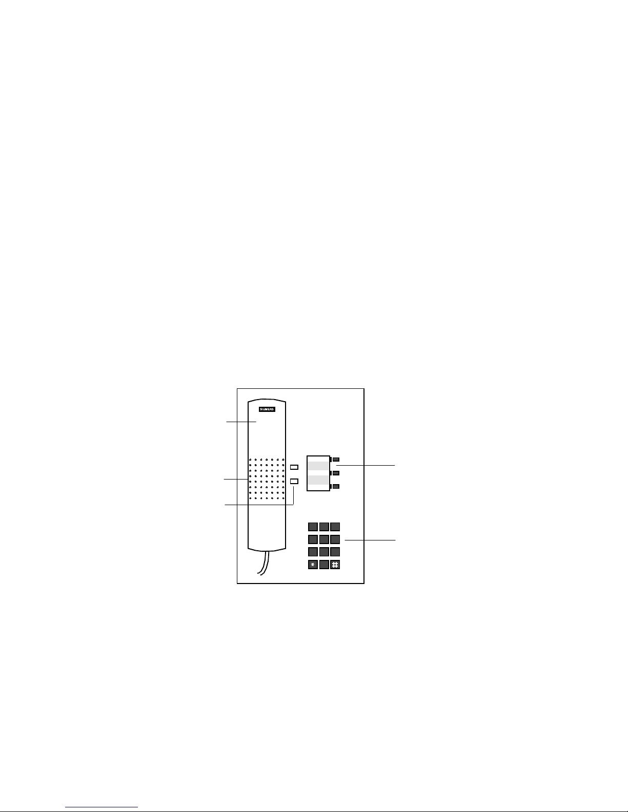
Optiset E Entry Telephone
The Entry phone has three feature keys, one for a single line
extension, two for optional features programmed at your
communications server. Its speaker is only used for the ringing
tone, not for voice transmission. When the phone is idle, users
cannot do “on hook” dialing, dialing after pressing the line key
or a feature key without lifting the handset. Instead, they must
pick up the handset before dialing or initiating features such as
Repdials for one-touch dialing, Station Speed Dialing, and
System Speed dialing.
1)
4)
5)
2)
3)
+
–
456
PQRS TUV WXYZ
789
ABC DEF
MNOJKLGHI
1 2 3
4
5 6
7 8 9
0
0
Figure 1. Optiset E Entry Telephone
1)
Handset
2)
Speaker for ringing tone only
3)
Keys for telephone settings
4)
3 feature keys with status lights
5)
Key pad
1
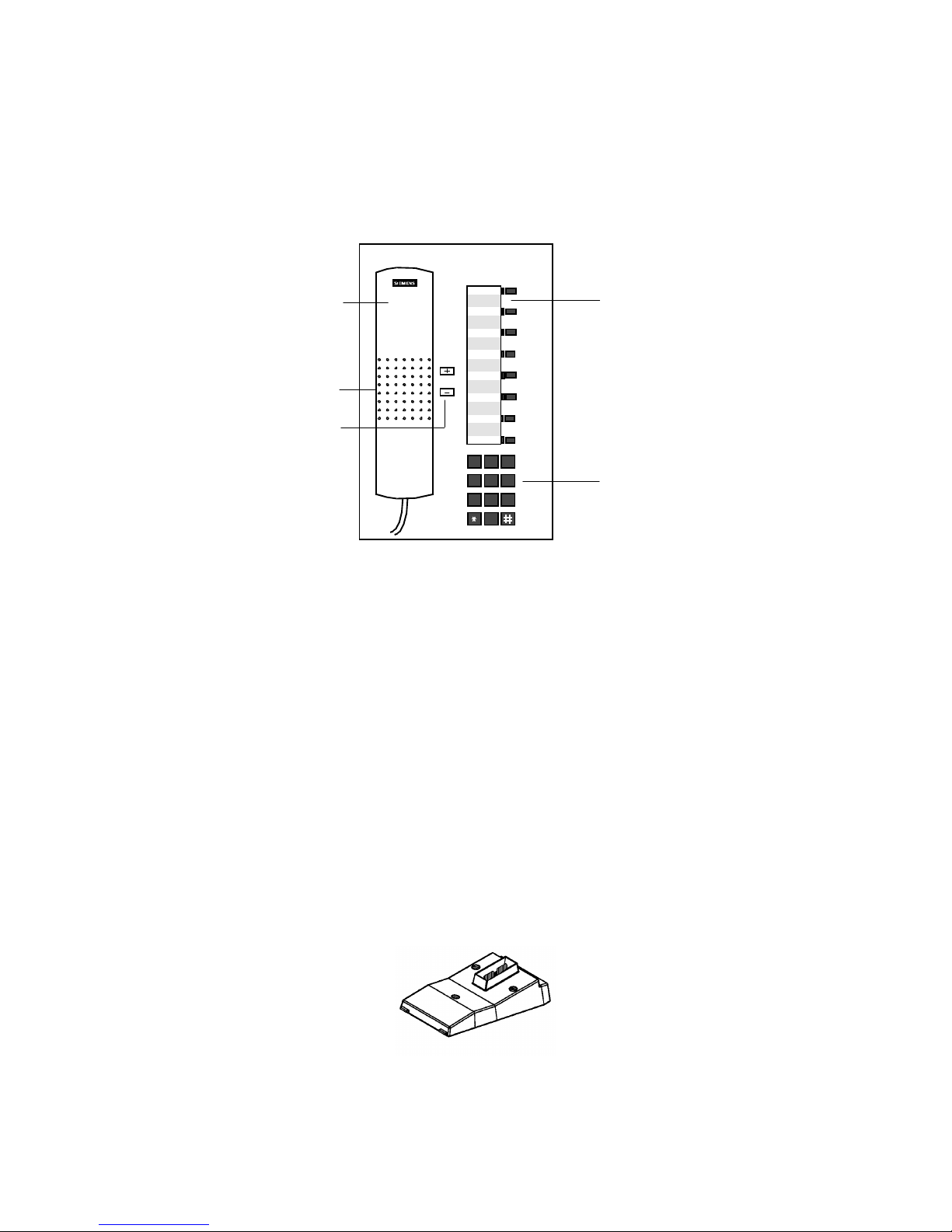
Optiset E Basic Telephone
1)
The Basic phone has a speaker and eight feature keys that may
be used for up to four multiple-line extensions and for features
programmed at your communications server. In addition, it has
one option bay underneath its base that supports user-installable
bay option modules.
4)
5)
2)
3)
1)
MNOJKLGHI
1 2 3
456
PQRS TUV WXYZ
4
5 6
789
789
0
0
Figure 2. Optiset E Basic Telephone
Handset
2)
Speaker (ringing tone/open listening)
3)
Keys for telephone settings
4)
8 feature keys with status lights
5)
Key pad
Bay Option Modules
The bay option modules snap into place in the bay underneath
the Basic phone. They are the same size and shape, but labels
clearly identify their type.
2
Figure 3. Bay Option Modules

Optiset E Analog Adapter
The Analog Adapter lets you attach a standard analog device,
such as a phone, facsimile machine, modem, or answering
machine, to your phone via an RJ11 connector on the back of
the adapter. The attached device is configured at your
communications server to be completely independent, with its
own phone number. It can be attached to a standard telephone
cable up to 300 ft. long. This adapter requires the Optiset E
Local Power Supply for operation. (See “Optiset E Local Power
Supply” on page 6.)
Optiset E Data Adapter
The Data Adapter lets you connect your phone to a computer or
terminal via a 25-pin connector for an EIA-232-E cable. You
can make asynchronous data calls by issuing AT commands
from your attached PC or terminal to your phone, much as you
would to an attached modem. This adapter supports baud rates
of up to 38.4 kilobytes per second (autobaud detection),
simultaneous voice and data communication, hardware flow
control (RTS/CTS) and full duplex operation. It also supports
the Siemens Application Programming Interface (API), data
loopback for customer service tests, and V.120 and DMI mode
2-Bit Rate Adaptation.
Optiset E ISDN Adapter
The ISDN Adapter lets you connect ISDN S0 bus devices such
as phones, PC cards, LAN Bridges, G4 fax machines, and video
equipment to your phone via an RJ45 connector. It supports up
to 64 kilobytes per second simultaneously on each bearer
channel. It will only work properly in a primary phone, not in a
phone attached to another phone with the Phone Adapter. You
can only connect two ISDN devices to the adapter.
Optiset E Phone Adapter
The Phone Adapter lets you attach another Optiset E phone to
your Basic phone. It provides an RJ11 connector to which you
can attach the second phone via a standard telephone cable up
to 300 feet long. You can then place the second phone in an area
not wired for a phone. The attached phone is configured at your
communications server to be a completely independent phone
with its own phone number.
3
2
1
3
4
5
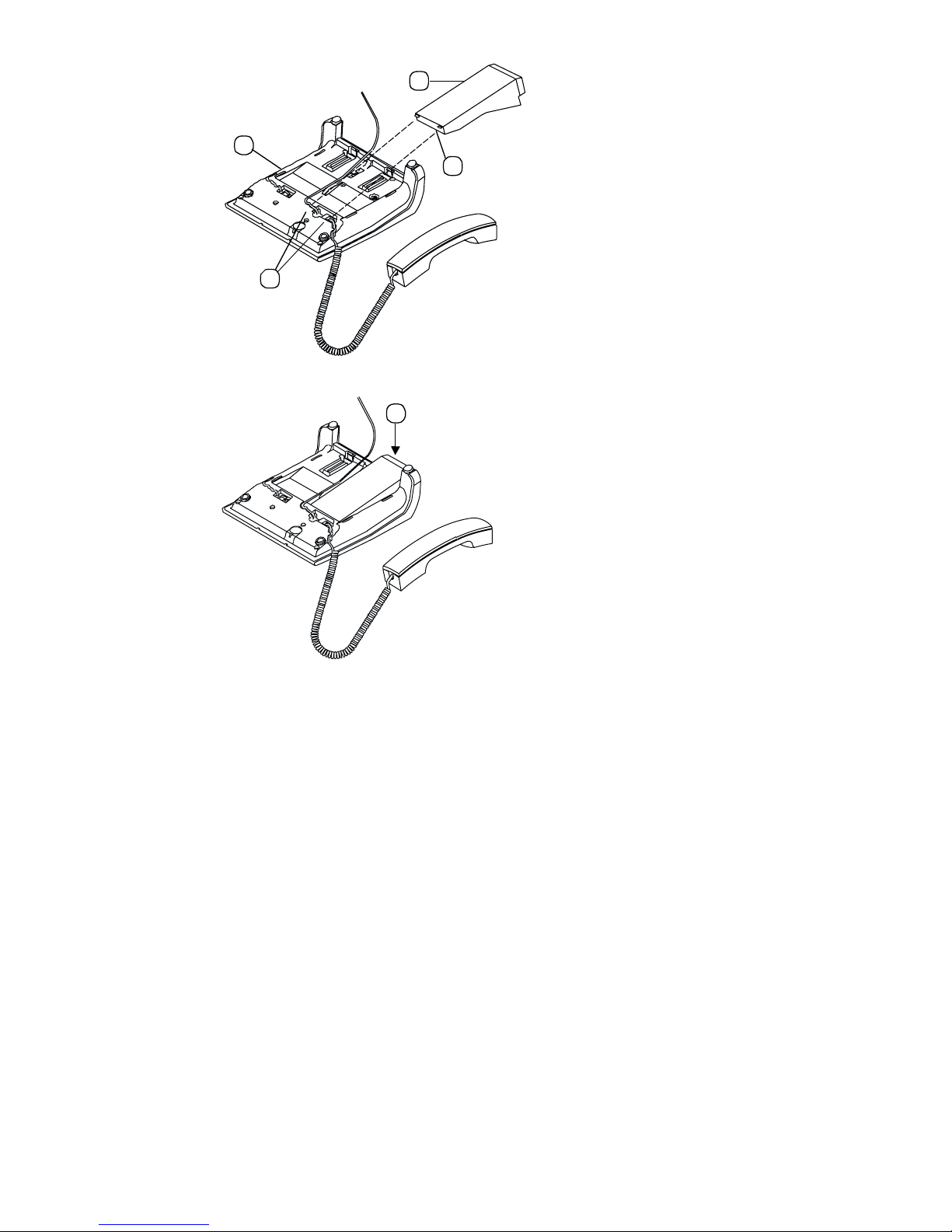
Figure 4. Installation of Bay Option Modules
1. Disconnect the phone line from the wall jack or phone and
place the phone ➀ on a soft surface with the keypad facing
down.
2. Hold the adapter ➁ with the male connector strip facing
down and mount it in the mounting location on the bottom of
the phone, sliding the two tabs ➂ into the two slots ➃.
3. Gently press down on the adapter until the male connector
strip is inserted all the way into the female connector strip ➄.
For the
Analog Adapter
, connect an analog device to the 6-pin
RJ11 port on the back of the Analog Adapter (connecting
tip/ring to pins 3 and 4). Reconnect the phone line to the phone.
Note that the analog adapter requires the Optiset E Local Power
Supply for operation.
For the
Data Adapter
, connect the data terminal equipment to
the 25-pin (EIA232) connector on the back of the Data Adapter.
Reconnect the phone line to the phone.
4

For the
ISDN Adapter
, connect the ISDN terminal to the RJ45
adapter. Reconnect the phone line to the phone.
For the
Phone Adapter
, connect the secondary Optiset E phone
into the RJ11 connector on the adapter. Reconnect the phone
line to the phone.
5

Optiset E Local Power Supply
u
The Local Power Supply is required for the Analog Adapter. It
may also be required in other situations, depending on the
Optiset E telephone’s configuration, the type of phone cable
used, the length of the phone cable from the communications
server, and the type of communications server used. Only one
Optiset E Local Power Supply can be used at a time on an
Optiset E phone. However, one Local Power Supply can be
used on a primary phone and a second Local Power Supply can
be used on a secondary phone attached to the primary phone
through a Phone Adapter.
Installation of Local Power Supply
To install a local power supply:
1. Disconnect the phone line from the wall jack and from the
phone. New phones should have a line cord attached to the
phone, but may not be plugged into the wall jack. Plug the
line cord (PN 51A4871) ➀ that comes with the power supply
into the jack on the phone and into the jack on the power
supply labeled .
Digital
2. Plug one end ➁ of the line cord that you disconnected from
the phone into the jack on the power supply labeled .
3. Plug the other end ➂ of this cord into the wall jack. Note that
you could plug it into an Optiset E Phone Adapter installed
in another properly installed phone instead.
4. Plug the power supply ➃ into a properly grounded 120 VAC
electrical outlet.
Digital
1
Advance Pl
4
2
3
6
 Loading...