

Siemens Optiset E Standard, Optiset E Advance, Optiset E Advance Plus, Optiset E Advance Conference Telephone Manual

NOTE: This equipment has been tested and found to comply with the limits
for a Class B digital device, pursuant to Part 15 of the FCC Rules. These
limits ar e designed to provide reasonable pr otection agai nst harmful
interference in a residential installation. This equipment generates, uses and
can radi ate radio frequency energy and, if not installed and used in
accorda nce w ith the instructions, may cause har mful interfere nce to radio
communic a tions. However, there is no guarant ee that interferen ce w ill not
occur in a particular installation. If this equipment does cause harmful
interf erence to radi o or television receptio n, which can be determined by
turnin g the equipment of f a nd on, the user is encouraged to try to correct the
interference by one or more of the following meas ures:
- Reorient or relocate t he r eceiving antenna.
- Increas e the separation bet we en the equipment and receiver.
- Connect the equipment into an outlet on a circuit different from that to
which the receiver is connected.
- Consult the dealer or an exper ienced radio/ TV technician for help.
WARNING: Changes or modifications to th e equipment that are not
expressly approved by t he responsible party for compliance could voi d the
user’s authority to operate the equipment.
This Class B digital apparatus complies with Canadian ICES-003.
Cet appareil numérique de la classe B est conf or me à la norme NMB-003 du
Canada.
Nov e mber 1998
Form No. GU30-1604-01 Part No. 06D8631 EC No. A93070
No part of t his publication may be reproduced, stored in a retriev al system, or
transmitted, in any form or by any means, mechanical, electronic, photocopying, recording, or otherwise, without prior wr it ten permis s ion of Siemens Business Communication Systems, Inc.
Request Si emens publicati ons f rom your Siemens representative or the Siemens branch serving you. Publica ti ons are not stocked at the address below.
Siemens Business Communication Systems, Inc.
4900 Old I ronsides Drive
P.O. Box 58075
Santa Clara, CA 95052-8075
(408) 492-2000
PhoneMail is a registered trademark and Opt iGuide is a tra demar k of Siemens
Business Communication Systems, Inc.
Siem e ns, Hicom, an d Op t i s e t are register ed tradem arks of S i emen s
Aktiengesellschaft.
Copyri ght Siemens Business Communication Systems, Inc. 1998.
All rights reserved.

Contents
Contents . . . . . . . . . . . . . . . . . . . . . . . . . . . . . . . . . . . . . . . . . i
Welcome to Your Optiset E Stan dard, Adv ance, Adva nce Pl us,
or Advance Conference Telephone . . . . . . . . . . . . . . . . . . . . 1
Optiset E Standard Telephone . . . . . . . . . . . . . . . . . . . . . . . . 2
Optiset E Advan ce , Advance Plus, and Advance Conf erence
Telephones . . . . . . . . . . . . . . . . . . . . . . . . . . . . . . . . . . . . . . . 3
Bay Option Modules . . . . . . . . . . . . . . . . . . . . . . . . . . . . . . . . 4
Optiset E Key Module . . . . . . . . . . . . . . . . . . . . . . . . . . . . . 10
Optiset E Local Power Supply . . . . . . . . . . . . . . . . . . . . . . . 10
Where to Go for Assistance . . . . . . . . . . . . . . . . . . . . . . . . . 11
Your Class of Service . . . . . . . . . . . . . . . . . . . . . . . . . . . . . . 11
Line Keys . . . . . . . . . . . . . . . . . . . . . . . . . . . . . . . . . . . . . . . 11
Status Lights . . . . . . . . . . . . . . . . . . . . . . . . . . . . . . . . . . . . . 12
The OptiGuide Display . . . . . . . . . . . . . . . . . . . . . . . . . . . . . 12
Feature Keys and Access Codes . . . . . . . . . . . . . . . . . . . . . . 17
Volume Keys . . . . . . . . . . . . . . . . . . . . . . . . . . . . . . . . . . . . 17
Sounds . . . . . . . . . . . . . . . . . . . . . . . . . . . . . . . . . . . . . . . . . . 17
Changing Your Audio Settings . . . . . . . . . . . . . . . . . . . . . . . 19
Callback Request . . . . . . . . . . . . . . . . . . . . . . . . . . . . . . . . . 20
Conference . . . . . . . . . . . . . . . . . . . . . . . . . . . . . . . . . . . . . . 21
Connect . . . . . . . . . . . . . . . . . . . . . . . . . . . . . . . . . . . . . . . . . 22
Consultation . . . . . . . . . . . . . . . . . . . . . . . . . . . . . . . . . . . . . 23
Forwarding . . . . . . . . . . . . . . . . . . . . . . . . . . . . . . . . . . . . . . 24
Hold . . . . . . . . . . . . . . . . . . . . . . . . . . . . . . . . . . . . . . . . . . . 26
Last Number Redial . . . . . . . . . . . . . . . . . . . . . . . . . . . . . . . 27
Mailbox . . . . . . . . . . . . . . . . . . . . . . . . . . . . . . . . . . . . . . . . . 28
Park . . . . . . . . . . . . . . . . . . . . . . . . . . . . . . . . . . . . . . . . . . . . 29
Pickup . . . . . . . . . . . . . . . . . . . . . . . . . . . . . . . . . . . . . . . . . . 30
Pick A Call and Add to Conference . . . . . . . . . . . . . . . . . . . 31
Preview . . . . . . . . . . . . . . . . . . . . . . . . . . . . . . . . . . . . . . . . . 32
Repertory Dialing (Repdial) Keys . . . . . . . . . . . . . . . . . . . . 33
Saved Number Redial . . . . . . . . . . . . . . . . . . . . . . . . . . . . . . 34
Speaker . . . . . . . . . . . . . . . . . . . . . . . . . . . . . . . . . . . . . . . . . 35
Speakerphone . . . . . . . . . . . . . . . . . . . . . . . . . . . . . . . . . . . . 35
Station Speed Dialing . . . . . . . . . . . . . . . . . . . . . . . . . . . . . . 36
System Speed Dialing . . . . . . . . . . . . . . . . . . . . . . . . . . . . . . 38
Transfer . . . . . . . . . . . . . . . . . . . . . . . . . . . . . . . . . . . . . . . . . 39
Feature Access Codes . . . . . . . . . . . . . . . . . . . . . . . . . . . . . . 40
i

ii
Welcome to Your Optiset E
Standard, Advance, Advance Plus,
or Advance Conference Telephone
The Optise t E Standard, Advance, Advance Plus, and
Advance Conference digital telephones work with your
compa n y’s Si emens
to give you advanced, easy-to-use telephone features. The
communications server
telecommunications system.
Hicom 300 E Communications Server
is your facility’s internal
1)
2)
3)
4)
5a)
+
–
1 2 3
123
4 5 6
456
PQRS TUV WX YZ
789
789
ABC DEF
0
0
MNOJKLGHI
6)
7)
8)
5b)
9)
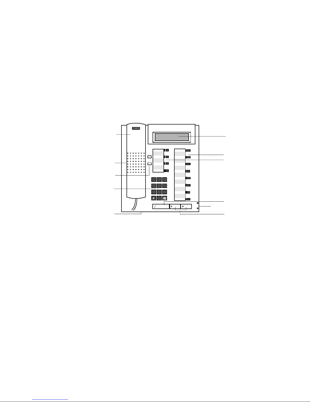
Figure 1. Optiset E Standard, Advance, Advance Plus, a nd
Advance Conference Telephones
Handset
1)
Speaker (ringin g tone/open listening)
2)
Keys f or telephone settings
3)
Key pad
4)
Microphone for handsfree talking
5a)
(for Optiset E Standard, Advance, and
Advance Plus)
Microphone for handsfree talking
5b)
(for Optiset E Advance Conf erence)
Display with 2 lines, 24 characters each
6)
Feature keys with status lights
7)
Guidance key "Select " (confirm s function)
8)
Guidance keys "Scrol l Forward" and
9)
“Scroll Back” for browsing
1

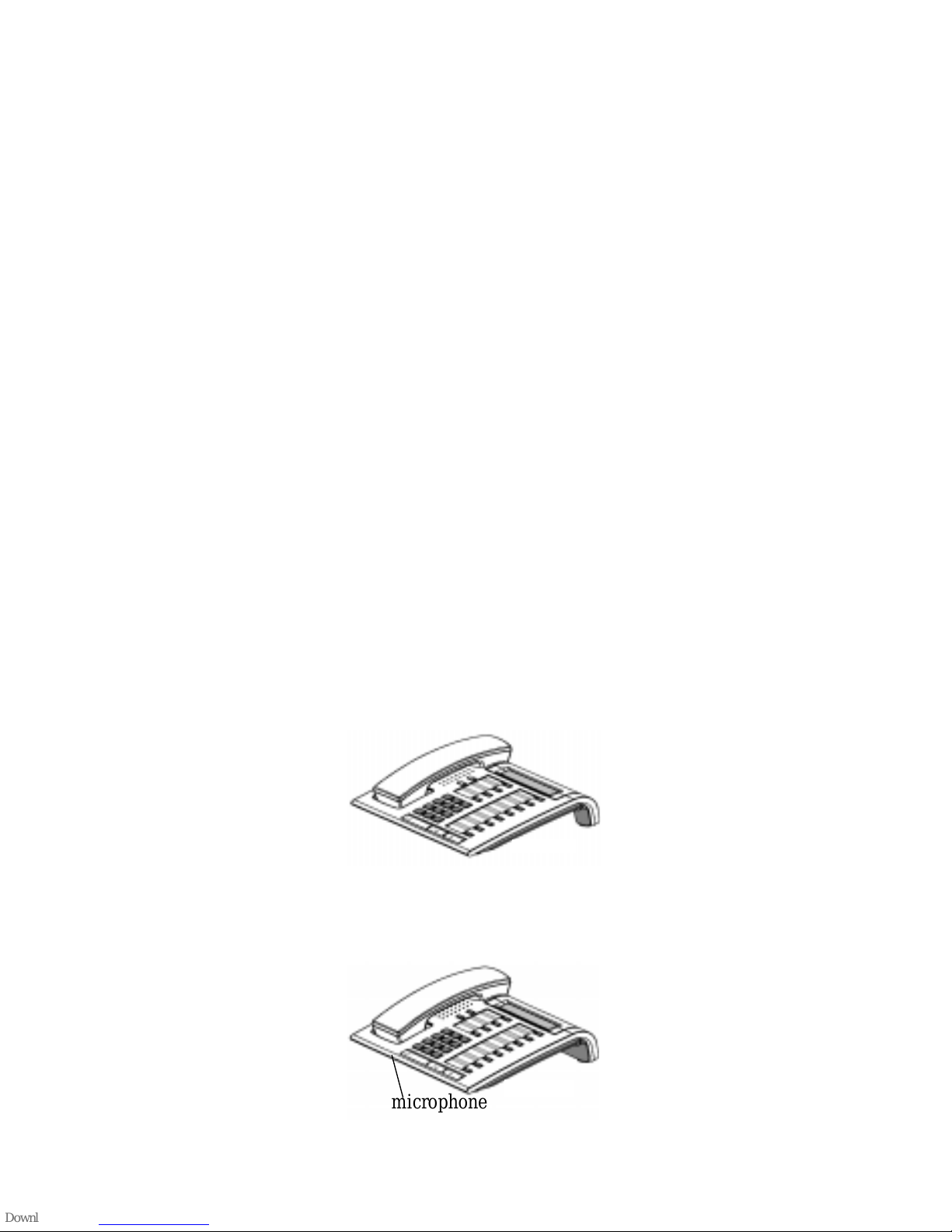
Optiset E Standard Telephone
The Optiset E Standard telephone has a micr ophone for a twoway speakerphone and does not support user-in st allable option
modules.
6WDQGDUG
microphone
Figure 2. Optiset E Standard Telephone
2
Optiset E Advance, Advance Plus,
and Advance Confer en ce
Telephones
The Optiset E Advance, Advance Plus, and Advance
Conference telephones have two bays, underneath their bases,
that sup port the following user-installable option modules :
• Optiset E Analog Adapter
• Optiset E Control Adapter
• Optiset E Speech Adapter (for Advance Conference
telephone only)
• Optiset E Data Adapter
• Optiset E Headset Adapter
• Optiset E Headset Plus Adapter
• Optiset E ISDN Adapter
• Optiset E Phone Ad ap ter
These phones also support up to four, side-mounted Optiset E
Key Module opti ons, for a total of 64 additional feature keys
and up to 29 line ex tensions. The Optis et E Advance Plus
telephone also has a microphone for a two-way speakerphone.
The Optise t E Advance Conferenc e telephone has a microphone
for a full duplex speakerphone.
$GYDQFH
Figure 3. Optiset E Advance Telephone
Figure 4. Optiset E Advance Plus Telephone
microphone
6WDQGDUG
3

6WDQGDUG
microphone
Figure 5. Optiset E Advance Conference Telephone
Bay Option Modules
The bay option mod ule s snap into pl ace in the bays unde rneath
the Advance, Advance Plus, and Advance Conference phones.
They ar e the same size and shape, but labels clearly identify
their type.
Figure 6. Bay Option Modules
Optiset E Analog Adapter
The Analog Adapte r lets you attach a standard analog device,
such as a phone, fa csimile machine, modem, or answering
machine, to your phone via an RJ11 connector on the back of
the adapter. The attached device is configured at your
communications server to be completely independent, with its
own phone number. The Analog Adapter can be attached to a
standard telephone cable up to 300 ft. long. This adapter
requires the Optiset E Local Power Supply for operati on. (See
“Optiset E Local Power Supply” on page 10.)
Optiset E Control Adapter
The Optiset E Control Adapter lets you connect an Optiset E
phone to a computer via a 9-pin EIA-232-E connection. This
option module provides a full Telephony Application
Programming In terface (TAPI) compli ant Computer Teleph ony
Interface (CTI) appli cation and simple AT command set dialing
inte r face. ComM an ager, for example, is a TAPI-compliant
application that works with the Control Adapter.
4

The Optise t E Control Adapte r supports baud rates up t o 19,200
bps for CTI applic ations. The option module does not support
asynchronous data calls or data communications parameters
such as hardware flow control (RTS/CTS). It does, however,
support AT comman ds for voice call control.
The Optiset E Control Adapter option module also has a
connector for an elec tret-style heads et.
The RJ8 (4-pin) headset int erfa ce sup ports any electret-style
headset or carbon-style headset with a configurable power
amplifier module. The RJ8 connector also supports all of the
features associated with other Optiset E Headset Option
modules, such as the ACD Auto Answer Mode.
Optiset E Speech Adapter
The Optiset E Advance Conference telephone supports the
Optiset E Speech Adapter option. The Speech Adapter is a
voice recognition module that gives you the abili ty to replace
keyboard entries with spoken commands us ing any of the
exist ing voice inputs of the phone to which it is attache d.
The Speech Adapt er al lows you to control the attached phone
locally by voice commands through the handset, head set, or
microphone fo r hand s-free mode. Feed back to t he use r is giv en
through dis play messages, voice prompts, and tone signals. A
mix of key strok es and voice commands is possible, making the
Speech Adapter opt ion very helpful in work places which
require real hands-free phone operation.
Optiset E Data Adapter
The Data Adapte r l ets you c onne ct you r ph one to a compute r o r
terminal vi a a 25-p in EIA-232-E connection. You can make
asynchronous data calls by issui ng AT co mmands from your
attached PC or terminal to your pho ne, much as y ou would t o an
attached modem. This adapter supports baud rates up to 38.4
kilobytes per second (autobaud detection), simul taneous voice
and data communication, hardware flow control (RTS/CTS)
and full duple x operation. It also supports the Siemens
Applicat ion Programming Interfa ce (API), data loopback for
customer service tests, and V.120 and DMI mode 2-Bit Rate
Adaptation.
Optiset E Headset Adapter
The Headset Adapter lets you plug one or two electret
microphone-t ype headse ts in to yo ur pho ne. You can the n mak e
and answer calls using a headset instead of the handset or the
phone’s bui lt-in microphone and spe aker. This type of headset
5

does not require an amplifier. Conne ctions are made through
two RJ8 connectors. Only the Optiset E Advance, Advance
Plus, and Advance Conference telephones support this option.
When a headset is plugge d int o the opt ion, the s peakerphone in
these telephones is disabled.
Optiset E Headset Plus Adapter
The Optiset E Headse t P lus Adapter lets you plug one or two
carbon microp hone-type headsets and a recorde r into your
phone. Thi s typ e o f he adset requ ires an a mplifi er. You can the n
make and a nswer cal ls us ing a heads et in stead of the hands et or
the phone’s built-in microphone and speaker. You can also
record your conversations. The recorder works without a
headset being attached.
The headsets attach to two RJ8 connectors. The recorder
attaches to an RJ11 connector. When a headset is plugged into
the option, the speakerphone in these telephones is disabled.
This adapt er does not have a two-prong PJ32 7 adapter interface .
Only the Optiset E Advance, Advance Plus, an d Advanc e
Conference telephones support this option.
Optiset E ISDN Adapter
The ISDN Adapter lets you connec t ISDN S0 bus devices such
as phones, PC c ards, LAN Bridg es, G4 fax machines , and vid eo
equipment to your phone via an RJ45 connector. It suppo rts up
to 64 kilobytes per second simultaneously on each bearer
channel. It will only work pr operly in a primar y phone, not in a
phone attached to another phone with the Phone Adapter. You
can only connect two ISDN devices to the adapter.
Optiset E Phone Adapter
The Phone Adapt er lets you attach another Optiset E phone to
your Basic phone. It provides an RJ11 con nector to which you
can attach the second phone via a st andard telephone ca ble up
to 300 fee t long. You can then p lace the s econd phone in an area
not wired for a phon e. The atta ched p hone i s con figu red at you r
communications server to be a completely independent phone
with its own phon e number.
6

Optiset E Teleworking Adapter
The Optiset E Teleworking Adapt er (OTA) is a component of
the Teleworking Application that enables an Opti set E display
telephone to be used by a remote teleworker or telecommute r .
Once the option module is installed, the Optiset E telephone
will work with all of the Hicom 300 E CS features available to
the tele phone when connected directly to the communications
server.
With th e O TA , a telewo rk er can repl icate th e co n f ig u r at i on of
his or h er office with regard to the PC an d telephon e equipment.
The OTA option requires a PC running the OTA Service
Sofware, a local power supply, and any one of the Optiset E
displa y phones. The adapter is a standard bay option module
that can be install ed underneath the base of th e phone, howe ver,
it can operate without being plugged into a telephone.
Note:
Refer to the
Teleworking Client Ins tallation and Guide
(G281-0518-00) for more information regarding this
application.
Only the Optiset E Standard, Advance, Advance Plus,
and Advance Conf erence telephones support this
option.
7
2
1
3
4
5
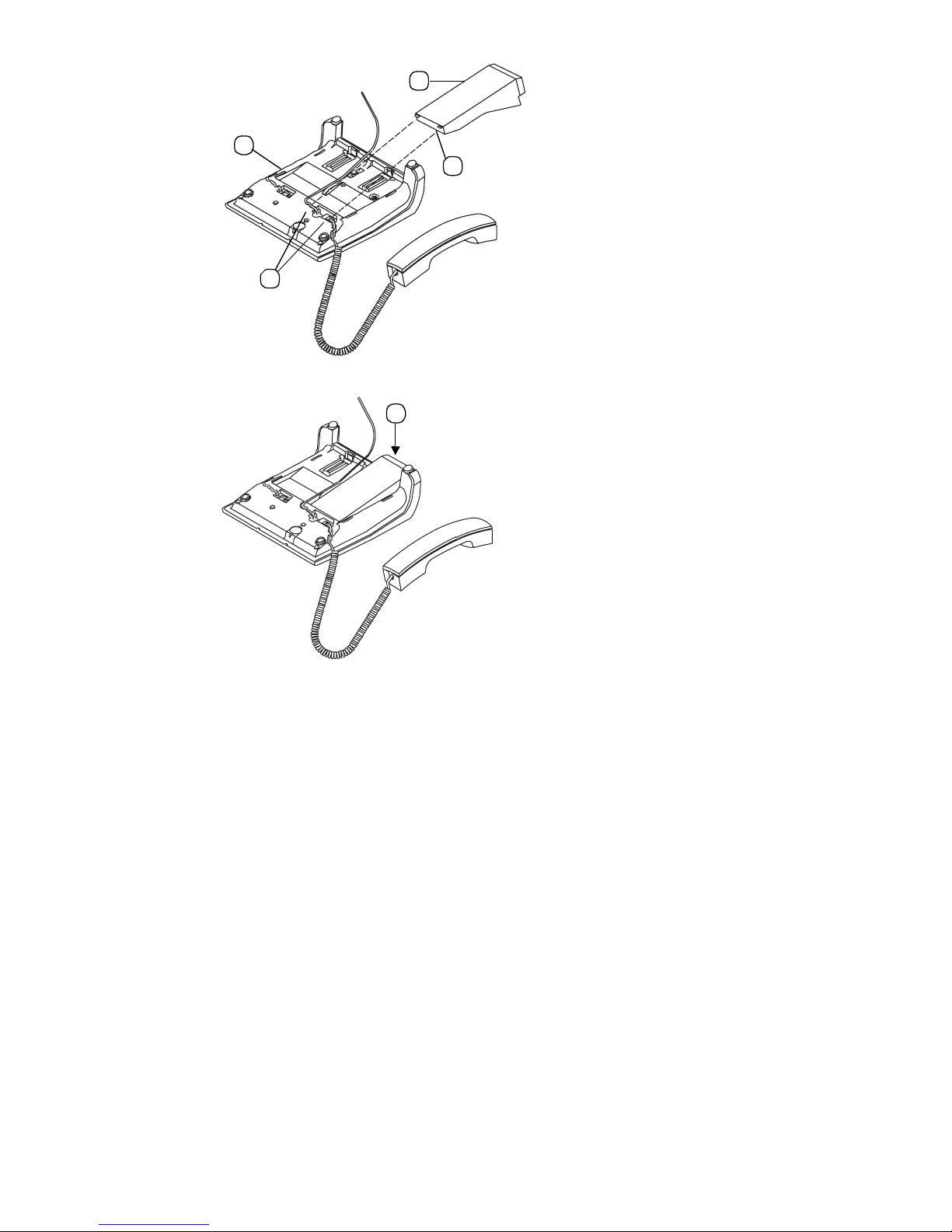
Figure 7. Install ati on of Bay Opti on M odules
1. Disconnect the phone line from the wall jack or phone and
place th e phone ➀ on a soft surface with the keypad facing
down.
2. Hold the adapter ➁ with the male connector strip facing
down and mount it in one of the two mounting locations on
the bottom of the phone, sliding the two tabs ➂ into the two
slots ➃.
3. Gently press down on the adapter until the male connector
stri p i s ins ert ed al l th e wa y int o th e fe ma le co nn ecto r st r ip ➄.
For the
Analog Adapter
, connect an analog device to the 6-pin
RJ11 port on the back of the Analog Adapter (connecting tip/
ring to pins 3 and 4). Reconnect the phone line to the phone.
Note that the analog adapter requires the Optiset E Local Power
Supply for operat ion.
For the
Control Adapter,
9-pin (RS-232) connector on the back of the Control Adapter.
8
connec t the person al computer to the

Connect the electret-style headset to the RJ 8 co n nector on the
adapter. Reconnect the phone line to the phone.
For the
Spee ch A da p t er
, connect the electret-style headset to
the RJ8 connec tor on the adapter. Reconnect the phone line to
the phone.
For the
Data Adapter
, connect the data terminal equipment to
the 25-pi n (EIA232) connect or on the ba ck of the Data Adapter.
Reconne ct the phone line to the phone.
For the
Headset Adapter,
connect the headset(s) to the headset
(RJ8 ) co nnector(s) on the adapt er . Reconnect the phone line to
the phone.
For the
Headset Plus Adapter
, connect the headset(s) to th e
headset (RJ8) connect or(s) on the ad apter. Co nnect the recorde r
to the recorder (RJ11) connector. Reconnect the phone line to
the phone.
For the
ISDN Adapter
, connec t t he I SDN te rminal to the RJ 45
adapter. Reconnect the phone line to the phone.
For the
Phone adapter
, connect the secondary Optis et E phone
into the RJ 11 connector on the adapter. Reconnect the phone
line to the phone.
For the
Teleworking adap ter
, connect the DB-9 data cable
betwe en the OTA and th e CO M p o r t of the PC. Connect the
custo m cab l e to th e U
from the O TA to the local power
p0/E
supply. Connect the line cord from the local power supply
(Digital) to the line cord connector on the Optiset E display
telephone. Connect the line cord from the anal og interface of
the OTA to the analog interface associated with the PC.
9

Optiset E Key Module
The side-mount ed Optiset E Key Module adds 16 keys for
features and li ne ext ensions . Up t o fou r Opt iset E Key Modul es
can be linked toge th er on one pho ne, for a t otal of 64 additi ona l
feature keys and up to 29 line extensions. Only the Optiset E
Advance and Advance Plus telephone s support this option.
Wall mount kits do not support phones with an Optiset E Key
Modu l e at tache d.
Figure 8. Optiset E Key Module
Optiset E Local Power Supply
The Local Power Supply is required for the Analog Adapter. It
may also be require d in other situations, depending on the
Optiset E te lephone’s configuration, the type of phone cable
used, the length of the phone cable from the communicat ions
serv er, and th e ty pe of communicati o ns serv er u sed. Only on e
Optiset E Local Power Su pply can be used at a time on an
Optiset E phone . Howe ver, one Local Power Supply can be
used on a prim ary phone and a s econd Local Po wer Supply c an
be used on a secondary phone attached to the primary phone
through a Phone Adapter.
Installation of Local Power Supply
To install a local power supply:
1. Disconnect the phone line from the wall jack and from the
phone. New phones should have a line cord attached to the
phone, but may not be plugged into the wall jack. Plug the
line cord (PN 51A4871) ➀ that comes with th e power supply
into the jack on the phone and into the jack on the power
supply la beled .
Digital
2. Plug one end ➁ of the line cord that you disconnected from
the phone into the jack on the power supply labeled .
10
 Loading...