

Siemens optiPoint 400 standard SIP Installation And Startup

SiP-Phone
optiPoint 400 standard SIP V2.0
Installation and Startup
The device conforms to the EU guideline 1999/5/EG, as attested by the CE mark.
This device has been manufactured in accordance with our certified environmental
management system (ISO 14001). This process ensures that energy consumption
and the use of primary raw materials are kept to a minimum, thus reducing waste
production.
Warnings!
– This is a class A product. In a domestic environment this product may cause
radio interference in which case the user may be required to take
adequate measures.
– If the optiPoint 400 standard SIP is supplied with power over the LAN interface,
the power source must be a limited power source PowerHub compliant with
IEC 60950.
Note! (for U.S.A and Canada only)
This equipment has been tested and found to comply with the limits for a Class B
digital device, pursuant to Part 15 of the FCC Rules. These limits are designed to
provide reasonable protection against harmful interference when the equipment is
operated in a residential installation. This equipment generates, uses, and can radiate radio frequency energy and, if not installed and used in accordance with the
instructions, may cause harmful interference to radio communications. However,
there is no guarantee that interference will not occur in a particular installation. If
this equipment does cause harmful interference to radio or television reception,
which can be determined by turning the equipment off and on, the user is encouraged to try to correct the interference by one or more of the following measures:
● Reorient or relocate the receiving antenna.
● Increase the separation between the equipment and receiver.
● Connect the equipment into an outlet on a circuit different from that to which
the receiver is connected.
● Consult the dealer or an experienced radio/TV technician for help.
This product is a UL Listed Accessory, I.T.E., in U.S.A. and Canada.
This guide for Installation and Startup describes how to connect
the components of the optiPoint 400 standard SIP telephone and
how to integrate the telephone into a LAN environment.
Administrators will find more detailed information in the “Administrator Manual”.
Preparing the telephone
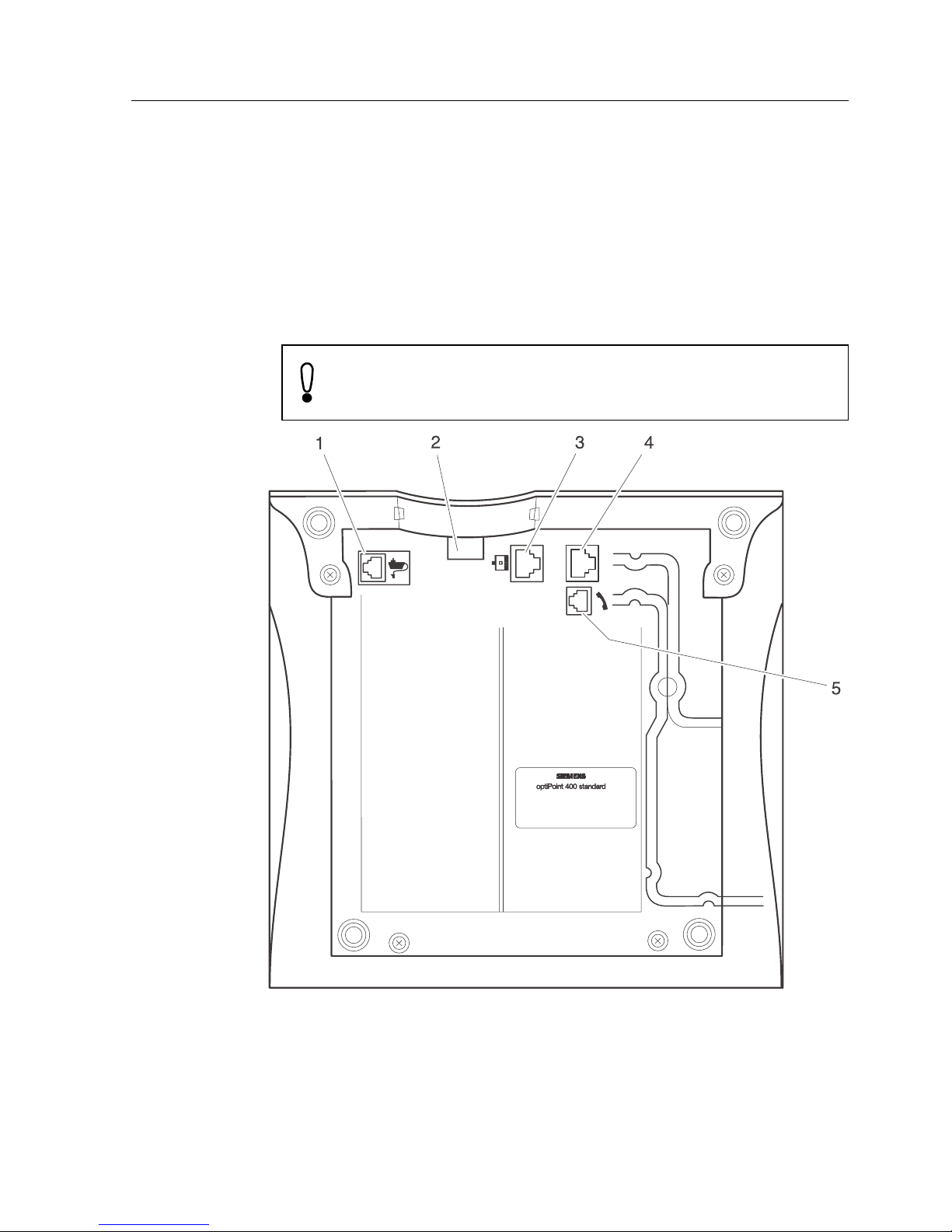
Warning!
You must connect the optiPoint 400 standard SIP first to
the LAN and after that to the power supply.
Installation and Startup
A31003-A2056-C202-52-76D1 3
Installation and Startup
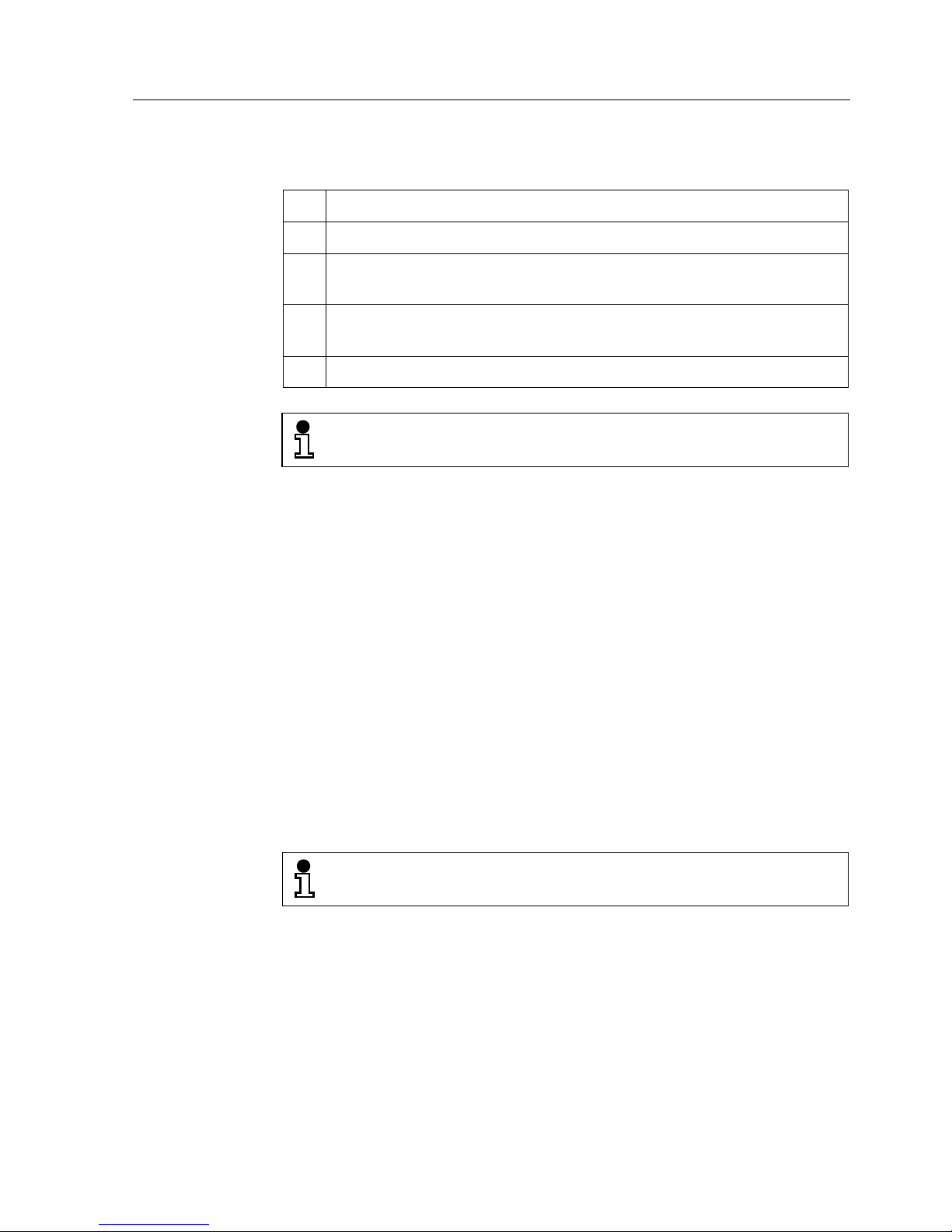
Housing elements and connections on the bottom of the telephone:
1 Connector for a local power supply unit (optional)
2 Strain relief
3 10/100 Mbit/s Ethernet port for LAN connection, autonegotiating
(optionally including power supply)
4 10/100 Mbit/s Ethernet port for optional connecting of a PC/work-
station, autonegotiating
5 Handset connector
The two cable ends of the handset cord are equipped
with identical four-pin Western plugs (RJ 11).
If power is supplied over the LAN cable, no local power supply is
required. To connect the telephone components:
● Plug the short end of the handset cable into the handset and
the other end into the connector a t the bottom of the telephone
(5). Feed the cab le through the guide channel in the base unit.
● Plug a LAN cable into the co nnecto r (3) of t he telep hone , a nd
connect with your LAN.
● Optionally you can connect a PC or a workstation directly to
the telephone. Plug a LAN cable into the connector (4) of the
telephone, and the other end into the PC/workstation connector.
● Plug the red Western plug of the optional po wer supply unit ca-
ble into the connector ( 1) on the bottom of the telephone . Feed
the cord through the strain relief clamp (2 ).
The Western plugs of all cab le connecti ons m ust a udib ly
snap into place.
● Feed the cables through the relief on the back of the housing
and fix them by means of the cable clip.
4 A31003-A2056-C202-52-76D1
 Loading...