

Siemens Operator Display Panel II Installation Instructions Manual
Installation Instructions
Document No. 570-111
February 18, 2013
Operator Display Panel II (ODP II)
Item No. 570-111. Rev. AA Page 1 of 4
Product Description
These instructions explain how to field install or
replace the BACnet Fume Hood Controller FHC.
The Fume Hood Controller Operator Display Panel
(ODP) is the interface between the fume hood
operator and the controller system. The mounting
plate is designed for the fume hoods with or without
existing cutouts.
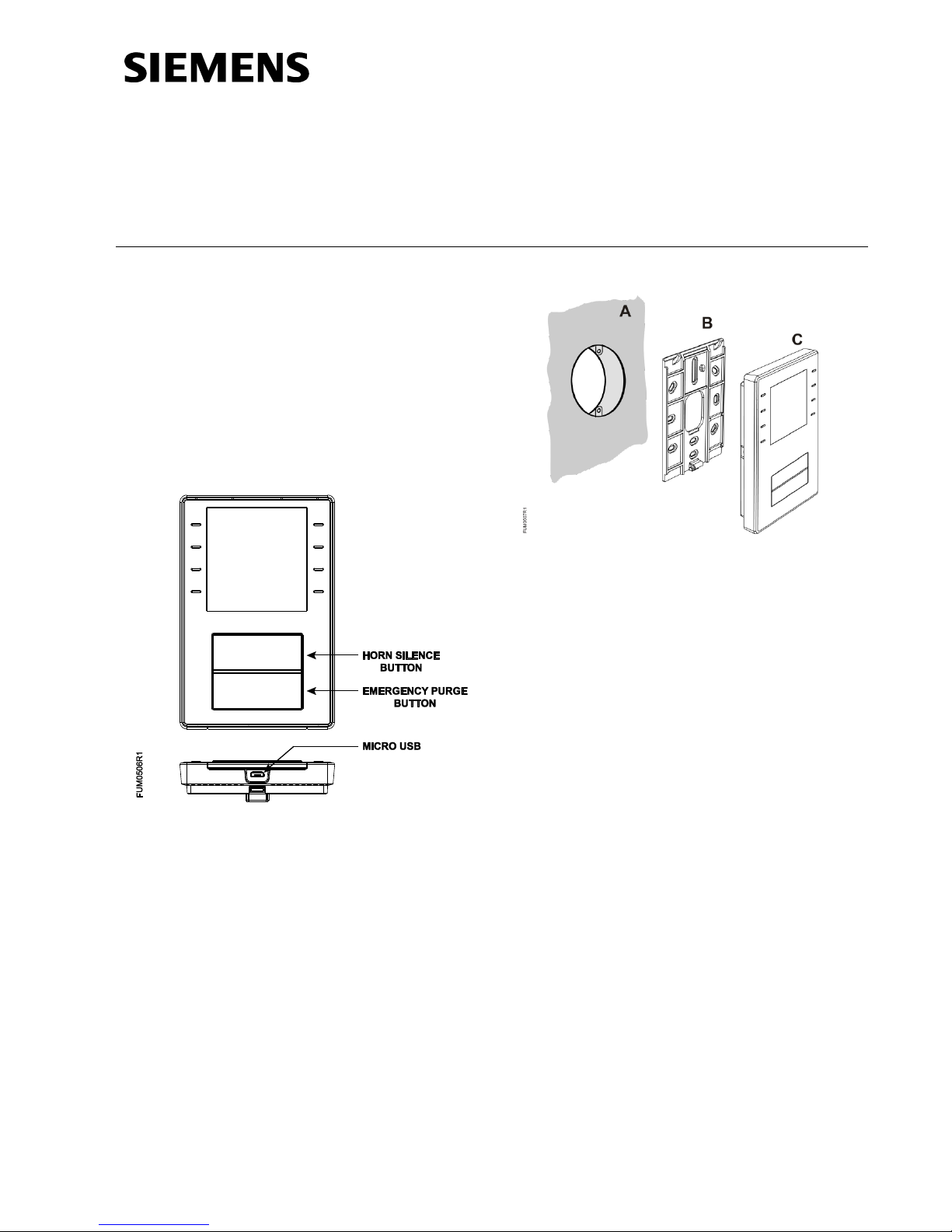
Designed for wall-mounting (A). A conduit box
is optional.
Base plate (B) has screw holes for all
commercially available conduit boxes. The
height of the screw heads must not exceed 3
mm.
Device (C) incorporates a plug, an LCD panel,
emergency purge and horn silence buttons.
Product Number
575-820A
Required Tools
For fume hood with an existing cutout, you need:
Medium Phillips-head screwdriver
For fume hood without a cutout, you need:
Medium duty electric drill
1-1/2 inch (38 mm) hole saw bit
Prerequisites
Cable from controller to ODP is in place.
Cable from controller to ODP is less then 50 feet
(15 m) in length.
Document No. 570-11
Installation Instructions
February 18, 2013
Page 2 of 4 Siemens Industry, Inc.
Installation Instructions
NOTE:
The ODP must be mounted so that the
fume hood operator can easily read its
display and reach its buttons.
1. Choose the mounting location for the ODP. The
panel can be mounted directly on the fume
hood over a pre-existing cutout, on a nearby
wall or over a conduit box.
2. Continue with one of the following:
- Installing a Cutout
- Installing the ODP
Installing a Cutout
1. Using the mounting plate as a template, mark
the location for the mounting holes and
interface cable/connector.
2. Drill the two mounting holes using a 3/16-inch
(5 mm) bit.
3. Cut the controller interface port clearance hole
using a 1-1/2 inch (38 mm) hole saw.
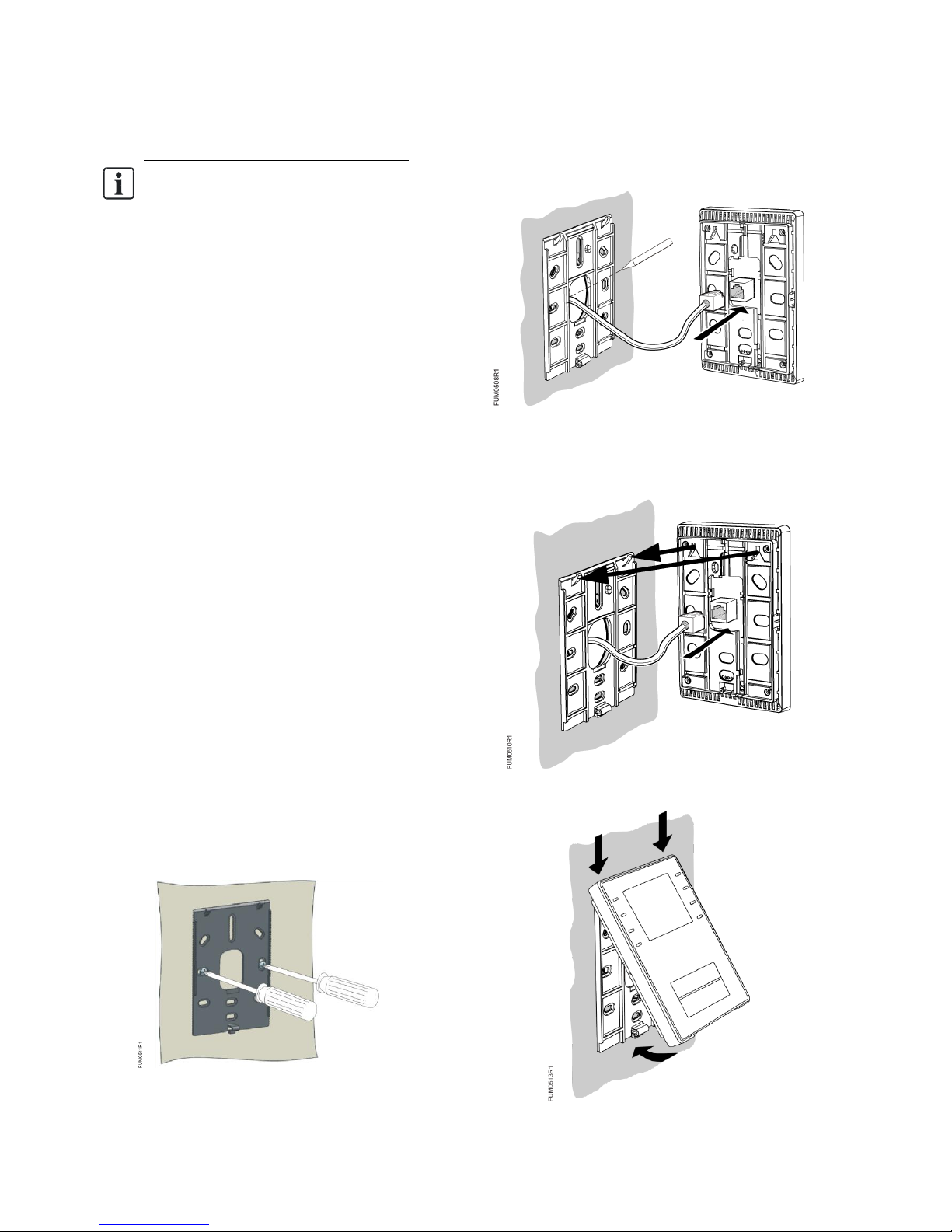
Installing the ODP
1. Position the mounting bracket over the existing
cutout on the fume hood. Align the holes on the
mounting bracket with the screw holes of the
cutout.
NOTE: Make sure that there is enough
clearance for the controller interface port on the
ODP.
2. Attach the mounting plate to the mounting
surface using the screws provided.
NOTE: The height of the screw heads must not
exceed 3 mm.
3. Pull the cable through the plate and connect it
to the ODP at the controller interface port.
4. Place the ODP onto the mounting bracket so
that the flange engages into the slots located
inside the top of the panel housing.
5. Push until locking tab clicks in place.
 Loading...