

Page 1
Arnold
Monitor 44cm, 100/120HZ
Maintenance Instructions
Monitor 44cm, 100/120HZ
SP
Monitor 44 cm, 100/120 Hz
The protocol SPR2-230.105.01.02.02 is required for
these instructions
Print No.:
Replaces: SPR2-230.101.01.01.02
SPR2-230.101.01.02.02
01102628
© Siemens AG
The reproduction, transmission or use
of this document or its contents is not
permitted without express written
authority. Offenders will be liable for
damages. All rights, including rights
created by patent grant or registration
of a utility model or design, are
reserved.
English
Doc. Gen. Date: 08.05
1998
Page 2

2 Revision / Disclaimer
1Revision / Disclaimer
Document revision level
The document corresponds to the version/revision level effective at the time of system
delivery. Revisions to hardcopy documentation are not automatically distributed.
Please contact your local Siemens office to order current revision levels.
Disclaimer
The installation and service of equipment described herein is to be performed by qualified
personnel who are employed by Siemens or one of its affiliates or who are otherwise
authorized by Siemens or one of its affiliates to provide such services.
Assemblers and other persons who are not employed by or otherwise directly affiliated
with or authorized by Siemens or one of its affiliates are directed to contact one of the
local offices of Siemens or one of its affiliates before attempting installation or service procedures.
Monitor 44cm, 100/120HZ SPR2-230.101.01.02.02 Siemens AG
08.05 CS PS 24
Page 2 of 26
Medical Solutions
Page 3

Table of Contents 3
0 Table of Contents
1 _______ General information______________________________________________ 4
Requirements . . . . . . . . . . . . . . . . . . . . . . . . . . . . . . . . . . . . . . . . . . . . . . . . . . . . . . . . . . 4
Required documents . . . . . . . . . . . . . . . . . . . . . . . . . . . . . . . . . . . . . . . . . . . . . . . . . . . . 5
Required tools, measurement and auxiliary devices . . . . . . . . . . . . . . . . . . . . . . . . . . . . 6
Emphasized text. . . . . . . . . . . . . . . . . . . . . . . . . . . . . . . . . . . . . . . . . . . . . . . . . . . . . . . . 7
Safety information and protective measures . . . . . . . . . . . . . . . . . . . . . . . . . . . . . . . . . . 8
General safety information (in existing documents) . . . . . . . . . . . . . . . . . . . . . . . . . . 8
General electrical safety information. . . . . . . . . . . . . . . . . . . . . . . . . . . . . . . . . . . . . . 8
Radiation safety information . . . . . . . . . . . . . . . . . . . . . . . . . . . . . . . . . . . . . . . . . . . . 9
Mechanical safety information . . . . . . . . . . . . . . . . . . . . . . . . . . . . . . . . . . . . . . . . . . 9
Safety information - risk of infection . . . . . . . . . . . . . . . . . . . . . . . . . . . . . . . . . . . . . 10
Information on the protective conductor resistance test . . . . . . . . . . . . . . . . . . . . . . 10
Information on measuring the system leakage current. . . . . . . . . . . . . . . . . . . . . . . 11
Descriptions of abbreviations . . . . . . . . . . . . . . . . . . . . . . . . . . . . . . . . . . . . . . . . . . . . . 15
Maintenance interval . . . . . . . . . . . . . . . . . . . . . . . . . . . . . . . . . . . . . . . . . . . . . . . . . . . 16
2 _______ Inspection of exterior and surroundings____________________________ 17
Inspection of exterior . . . . . . . . . . . . . . . . . . . . . . . . . . . . . . . . . . . . . . . . . . . . . . . . . . . 17
Inspection of surroundings . . . . . . . . . . . . . . . . . . . . . . . . . . . . . . . . . . . . . . . . . . . . . . . 18
Power outlets . . . . . . . . . . . . . . . . . . . . . . . . . . . . . . . . . . . . . . . . . . . . . . . . . . . . . . 18
3 _______ Safety inspection _______________________________________________ 19
Mechanical safety. . . . . . . . . . . . . . . . . . . . . . . . . . . . . . . . . . . . . . . . . . . . . . . . . . . . . . 19
Electrical safety . . . . . . . . . . . . . . . . . . . . . . . . . . . . . . . . . . . . . . . . . . . . . . . . . . . . . . . 20
4 _______ Maintenance, operating value/functional inspection __________________ 23
Maintenance. . . . . . . . . . . . . . . . . . . . . . . . . . . . . . . . . . . . . . . . . . . . . . . . . . . . . . . . . . 23
5 _______ Final result/quality inspection and maintenance _____________________ 24
6 _______ Changes to Previous Version_____________________________________ 25
Siemens AG SPR2-230.101.01.02.02 Monitor 44cm, 100/120HZ
Medical Solutions
08.05 CS PS 24
Page 3 of 26
Page 4

4 General information
1-
1 General information
1.1 Requirements
These maintenance instructions apply to the 100/120 Hz standard monitor,
part number 30 64 581 B5310.
The monitor is a component of the system or system configuration. Maintenance for
these systems or system configurations should be performed in accordance with the corresponding maintenance instructions.
Monitor 44cm, 100/120HZ SPR2-230.101.01.02.02 Siemens AG
08.05 CS PS 24
Page 4 of 26
Medical Solutions
Page 5

General information 5
1.2 Required documents
• Safety information according to ARTD, part 2
• Maintenance protocol SPR2-230.105.01..
• System binder for the system or system configura-
tion
Siemens AG SPR2-230.101.01.02.02 Monitor 44cm, 100/120HZ
Medical Solutions
08.05 CS PS 24
Page 5 of 26
Page 6
6 General information
1.3 Required tools, measurement and auxiliary devices
NOTE
Tool For example Material no.:
The indicated articles are listed in the STC (Service Tools Catalog)
unless otherwise stated (the STC is a component of the Spare
Parts Catalog), except for those items identified with "*".
• Standard tool kit*
• Set of Allen keys*
• Protective conductor tester Safety tester UNIMRT 1100 51 38 727
• Luminance meter SPOTMETER for SM fit ACT 77 52 848
Monitor 44cm, 100/120HZ SPR2-230.101.01.02.02 Siemens AG
08.05 CS PS 24
Page 6 of 26
Medical Solutions
Page 7
General information 7
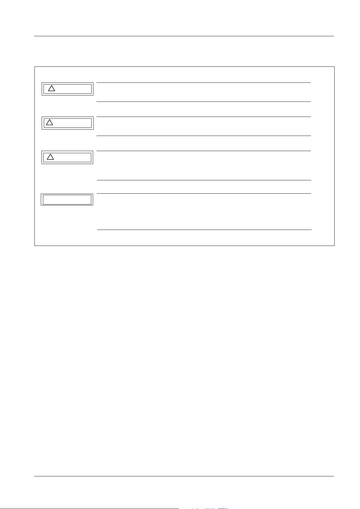
1.4 Emphasized text
!
DANGER
!
WARNING
!
CAUTION
NOTICE
Fig. 1: Safety Notes
DANGER indicates when there is an immediate danger that
l e a d s to death or serious physical injury.
WARNING indicates a risk of danger that m a y l e a d to death
or serious physical injury.
CAUTION used with the safety alert symbol indicates a risk of
danger that leads to slight or moderate physical injury and/ or
damage to property.
NOTICE used without the safety alert symbol indicates a risk of
danger that if disregarded leads or may lead to a potential
situation which may result in an undesirable result or state other
than death, physical injury or property damage.
Siemens AG SPR2-230.101.01.02.02 Monitor 44cm, 100/120HZ
Medical Solutions
08.05 CS PS 24
Page 7 of 26
Page 8
8 General information
1.5 Safety information and protective measures
1.5.1 General safety information (in existing documents)
WARNING
Risk of injury, death or material damage.
Note
¹ The product-specific safety notes in these instructions,
¹ The general safety information in TD00-000.860.01... and
¹ The safety information in accordance with ARTD Part 2.
¹ Non-compliance can lead to death, injury or material
damage.
1.5.2 General electrical safety information
WARNING
Electrical safety!
Non-compliance can lead to severe injury or even death and mate-
rial damage.
¹ After opening the covers, the parts under voltage are
accessible. To avoid danger, disconnect the system from
the power supply prior to opening the covers. Disconnect the power plug.
CAUTION
¹ If an uninterruptible power supply (UPS) is installed in
the system, the voltage output of the UPS must also be
deenergized or the voltage output plug must be disconnected.
¹ If work has to be performed under electrical voltage, the
general safety information according to
TD00-000.860.01... must be complied with.
Electrical voltage!
Non-compliance can result in material damage.
¹ When working on the system, ESD regulations must be
observed.
Monitor 44cm, 100/120HZ SPR2-230.101.01.02.02 Siemens AG
08.05 CS PS 24
Page 8 of 26
Medical Solutions
Page 9
General information 9
1.5.3 Radiation safety information
WARNING
X-ray radiation!
Non-compliance can lead to illness, irreversible damage to body
cells and the genotype, severe injury and even death.
When performing work on the system during which radiation must
be released, the radiation protection directives and the rules for radiation protection according to ARTD 02.731.02 must be complied
with.
¹ Please note:
¹ Use available radiation protection devices.
¹ Wear radiation protection clothing (lead apron).
¹ Stay as far away as possible from the radiation source.
¹ Release radiation only if necessary.
¹ Set the radiation activity as low as possible. (low kV and
mA values, short radiation time)
¹ Release radiation for as short a time as possible.
¹ Checks in which radiation must be released are identified
by the radiation warning symbol.
1.5.4 Mechanical safety information
CAUTION
CAUTION
Risk of burns from hot parts or components! Non-compliance can
result in minor to more severe burns, especially on the hands.
Parts and components (e.g., power components, cooling element,
electromagnetic brakes) that can exceed 50 degrees Celsius during operation are accessible after the covers are opened.
¹ To avoid burns, switch the system off prior to touching
parts or components and allow at least 5 minutes of cooling.
Risk of injury from mechanical parts! Non-compliance can result
in minor to more severe injury, especially to the hands.
Parts such as flat plugs, threaded bolts, cut-off cable ties and component edges that, if care is not taken, can cause crushing, abrasion and cuts to the skin, particularly to the hands, can be touched
after the covers are opened.
¹ Perform the required work with special care and atten-
tion to detail.
¹ If needed, wear work gloves.
Siemens AG SPR2-230.101.01.02.02 Monitor 44cm, 100/120HZ
Medical Solutions
08.05 CS PS 24
Page 9 of 26
Page 10

10 General information
1.5.5 Safety information - risk of infection
WARNING
Risk of infection due to pathogens! Non-compliance can lead to
severe injury and even death.
This product can be contaminated by infected blood or other bodily fluids.
¹ Avoid all contact with blood or other bodily fluids!
¹ Strictly observe the safety information in
ARTD-002.731.37... regarding prevention of infectious
diseases during customer service calls.
1.5.6 Information on the protective conductor resistance test
Observe the instructions in the safety rules for installation and repair (ARTD-002.731.17
...).
The protective conductor resistance is to be measured, documented, and evaluated during maintenance.
NOTE
Evaluate the results by comparing the first measured value to the
corresponding values documented during preceding maintenance
procedures or safety checks.
A sudden or unexpected increase in the measured values may indicate a defect in the protective conductor connections - even if
the limit value of 0.2 ohms is not exceeded.
(Protective conductor or contacts).
The measurement must be performed according to DIN VDE 0751, Part 1 (see ARTD
Part 2). In this case the protective conductor resistance for all touchable conductive parts
must be measured during the normal operating state of the system.
Make sure that control cables or data cables between the components of the system are
not mistaken for a protective conductor connection.
During the measurement, move the power cable and additional connection cables with an
integrated protective conductor section by section to detect cable breaks.
Units with fixed power line connection:
The protective conductor resistance of 0.2 ohms must not be exceeded.
Units with detachable power cable:
The protective conductor resistance of 0.2 ohms for the unit with a power line connection
must not be exceeded.
The protective conductor resistance of 0.1 ohms for the detachable power line connection
must not be exceeded.
The protective conductor resistance of 0.1 ohms between the ground contact of the unit
plug and the touchable conductive unit parts may not be exceeded.
Monitor 44cm, 100/120HZ SPR2-230.101.01.02.02 Siemens AG
08.05 CS PS 24
Page 10 of 26
Medical Solutions
Page 11
General information 11
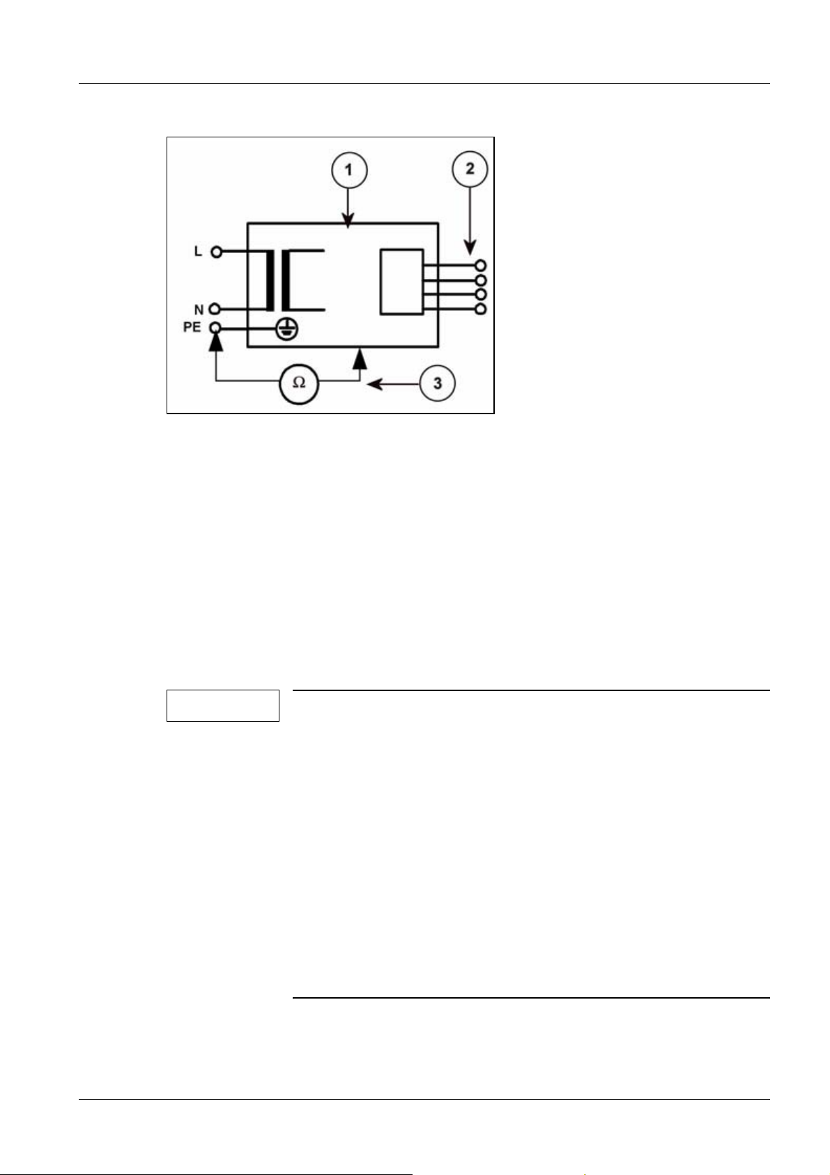
Fig. 2: Measuring circuit for measuring the protective conductor resistance in units/systems that
Pos. 1 System
Pos. 2 Application part (not available)
Pos. 3 Measurement setup (integrated into measuring device)
are permanently connected to the power supply net (according to DIN VDE
0751-1:2001-10, Fig. C3).
The determined values, including the measuring points, must be recorded and assessed
in the protective conductor resistance report.
The measuring procedure and the measuring device used (designation and serial number) are also to be documented.
1.5.7 Information on measuring the system leakage current
NOTE
The system leakage current measurement is to be conducted and
recorded as the repeat measurement during maintenance.
However, the first measured value must be newly determined and
a new report must created under the following conditions:
Lack of system leakage current measurement documentation
Local line voltage or line frequency deviating from the line voltage
and line frequency documented in the report (e.g. in the event of a
site/operator change)
Use of a different procedure for measuring the system leakage current from the one documented in the report.
For the purpose of traceability, reference to the new report is to be
written on the old report. The reason for newly determining the
first measured value is to be documented and confirmed with a
name and signature.
Siemens AG SPR2-230.101.01.02.02 Monitor 44cm, 100/120HZ
Medical Solutions
08.05 CS PS 24
Page 11 of 26
Page 12

12 General information
Observe the instructions in the safety rules for installation and repair (ARTD-002.731.17
...).
WARNING
Electrical voltage!
Non-compliance can lead to severe injury and even death.
¹ The system leakage current measurement may be per-
formed on systems of protection class I only after the
protective conductor test has been passed.
First measured value
The first measured value was already determined and documented in the system leakage
current report. The measuring procedure was also recorded.
The measurement was performed with the recorded line voltage, line frequency and with
the recorded measuring equipment.
Measurement
Perform the measurement according to DIN VDE 0751, Part 1 (see ARTD-002.731.17....),
and record the determined value.
The measuring procedure indicated in the report must be used.
If the first measured value has to be newly determined (see note), a measuring procedure
can be selected (direct measurement or differential measurement).
Measurement of the system leakage current according to the differential current method
(Fig.3/p.12) must be given preference, since this method is not dangerous to the per-
son performing the measurement and other persons.
However, please note the minimum resolution of the leakage current measuring instrument and any additional manufacturer's data restricting the use of the measuring device.
Fig. 3: Measuring circuit for measuring the system leakage current according to the differential
current method in compliance with DIN VDE 0751-1:2001-10, Fig. C6 for protection class
Monitor 44cm, 100/120HZ SPR2-230.101.01.02.02 Siemens AG
08.05 CS PS 24
Page 12 of 26
Medical Solutions
Page 13

General information 13
I.
Pos. 1 System
Pos. 2 Application part (not available)
Pos. 3 Measurement setup (integrated into measuring device)
If the direct measurement of the system leakage current is used (Fig.4/p.13), the sys-
tem must be insulated during the measurement and must not be touched.
Fig. 4: Measuring circuit for direct measurement of the system leakage current in compliance
with DIN VDE 0751-1:2001-10, Fig. C5 for protection class I.
Pos. 1 System
Pos. 2 Application part (not available)
Pos. 3 Measurement setup (integrated into measuring device)
WARNING
Electrical voltage!
Non-compliance can lead to severe injury and even death.
No housing parts of the system may be touched during direct mea-
surement of the system leakage current (Fig.4/p.13).
¹ Third-person access to the system must be prevented.
The system must be switched on during measurement. Measuring devices with automated measuring sequences must therefore be set to manual measurement.
The highest value must be entered in the system leakage current report.
This value must not exceed the permissible leakage current values according to DIN VDE
0751-1:2001-10, Table F.1, line "general leakage current information", of 0.5 mA.
Measure and record the current line voltage. If the measured line voltage deviates from
the nominal voltage, correct the measured value to the value corresponding to a measurement at the nominal value of the line voltage. This is also to be documented.
Document the measuring procedure (differential measurement or direct measurement)
and the measuring device used (designation and serial number).
In the case of repeat measurements, the measured value is also to be evaluated.
Siemens AG SPR2-230.101.01.02.02 Monitor 44cm, 100/120HZ
Medical Solutions
08.05 CS PS 24
Page 13 of 26
Page 14

14 General information
NOTE
Evaluate the results by comparing the first measured value to the
corresponding values documented during preceding maintenance
procedures or safety checks.
A sudden or unexpected increase in the measured values may indicate that a fault has occurred in the primary circuit of the power
supply (damaged insulation, damage caused by water ingress or
humidity, defective interference suppressor, etc.) - even if the limit
value of 2.5 mA is not exceeded.
The evaluation is not necessary in the case of a new determination.
File the report sheet in the system folder or log book.
Monitor 44cm, 100/120HZ SPR2-230.101.01.02.02 Siemens AG
08.05 CS PS 24
Page 14 of 26
Medical Solutions
Page 15
General information 15
1.6 Descriptions of abbreviations
Abbrev. Description
SI Safety Inspection
SIE Electrical Safety
SIM Mechanical Safety
PM Preventive Maintenance
PMP Periodic Preventive Maintenance
PMA Preventive Maintenance Adjustments
PMF Preventive Maintenance, Operating Value Check, Function Check
Q Quality Check
QIQ Image Quality
QSQ System Quality Check
SW Software Maintenance
The steps identified by these abbreviations are part of the maintenance report and should
be checked off upon completion.
NOTE
The sequence for complete maintenance and inspection is described on the following pages.
Each work step must be performed on an annual basis, if not otherwise specified.
Siemens AG SPR2-230.101.01.02.02 Monitor 44cm, 100/120HZ
Medical Solutions
08.05 CS PS 24
Page 15 of 26
Page 16

16 General information
1.7 Maintenance interval
12 months
Monitor 44cm, 100/120HZ SPR2-230.101.01.02.02 Siemens AG
08.05 CS PS 24
Page 16 of 26
Medical Solutions
Page 17

Inspection of exterior and surroundings 17
2-
2 Inspection of exterior and surroundings
2.1 Inspection of exterior
PMP Damage
Inspect the monitor for damage, e.g. to the housing or to the finish.
Siemens AG SPR2-230.101.01.02.02 Monitor 44cm, 100/120HZ
Medical Solutions
08.05 CS PS 24
Page 17 of 26
Page 18

18 Inspection of exterior and surroundings
2.2 Inspection of surroundings
2.2.1 Power outlets
SIE Damage
For monitors connected directly to the power supply:
• Inspect the power outlet for damage.
SIE Line voltage
• Measure the line voltage and compare this value to the line voltage for the monitor.
Monitor 44cm, 100/120HZ SPR2-230.101.01.02.02 Siemens AG
08.05 CS PS 24
Page 18 of 26
Medical Solutions
Page 19

Safety inspection 19
3-
3 Safety inspection
3.1 Mechanical safety
SIM Monitor mounting
• Inspect the monitor mounting on the console (rotating/tilting console or monitor holder)
for any mechanic damage.
SIM Console mounting
• Inspect the console (rotating/tilting console or monitor holder) for mechanical damage
and correct mounting.
SIM Warning labels
• Ensure that all required warning labels are attached and in good condition.
¹ Replace any illegible labels.
SIM ID labels
• Ensure that all required ID labels are attached and in good condition.
¹ Replace any illegible labels.
Siemens AG SPR2-230.101.01.02.02 Monitor 44cm, 100/120HZ
Medical Solutions
08.05 CS PS 24
Page 19 of 26
Page 20
20 Safety inspection
3.2 Electrical safety
SIE Cables and plugs
• Check visible cables and plugs of the monitor for damage
SIE Protective conductor test
NOTE
NOTE
The protective conductor test for the monitors is to be performed
when these are externally mounted (e.g. on a wall console). It is not
necessary to perform the protective conductor test for monitors
mounted on the monitor trolley of the system if they are tested during the protective conductor test of the system (e.g., SIREMOBIL
system).
Observe the notes on the protective conductor test in these instructions. The power cable of the monitor is to be moved section
by section during the protective conductor test to detect cable
breaks.
• If covers were removed, they are to be reattached.
• Perform the protective conductor test according to ARTD-002.731.17... .
• The protective conductor resistance of 0.2 ohms for the unit with a power line connec-
tion must not be exceeded.
The protective conductor resistance of 0.1 ohms for the detachable power cable must
not be exceeded.
The protective conductor resistance of 0.1 ohms between the ground contact of the unit
plug and the touchable conductive unit parts may not be exceeded.
• The determined values, including the measuring points, must be recorded and as-
sessed.
• The measuring procedure and the measuring device used (designation and serial num-
ber) are also to be documented.
NOTE
SIE Leakage current
Evaluate the results by comparing the first measured value to the
corresponding values documented during preceding maintenance
procedures or safety checks.
A sudden or unexpected increase in the measured values may indicate a defect in the protective conductor connection - even if the
limit value of 0.2 ohms is not exceeded.
(Protective conductor or contacts)
Monitor 44cm, 100/120HZ SPR2-230.101.01.02.02 Siemens AG
08.05 CS PS 24
Page 20 of 26
Medical Solutions
Page 21

Safety inspection 21
NOTE
NOTE
WARNING
WARNING
The leakage current measurement for monitors is to be performed
when these are externally mounted (e.g. on a wall console) and externally connected to a power outlet/power supply.
It is not necessary to perform the leakage current measurement for
monitors mounted on the monitor trolley of the system if they are
part of the secondary circuit of the system power supply (e.g.,
SIREMOBIL Compact/Iso-C/POWERMOBIL/ARCADIS Varic/ARCADIS Orbic).
Observe the leakage current measurement information in these instructions.
Electrical voltage!
Non-compliance can lead to severe injury and even death.
¹ The leakage current measurement may be performed on
systems of protection class I only after the protective
conductor test has been passed.
Electrical voltage!
Non-compliance can lead to severe injury and even death.
¹ No housing parts of the system may be touched during
direct measurement of the leakage current (measurement setup according to Fig. 26). Third-person access to
the system must be prevented.
• If covers were removed, they are to be reattached.
• Perform the leakage current measurement according to ARTD-002.731.17... .
• The highest value must be entered in the leakage current report.
• This value must not exceed the permissible leakage current values according to DIN
VDE 0751-01:2001-10, Table F.1, line "general leakage current information",
• of 0.5 mA.
• Measure and record the current line voltage. If the measured line voltage value devi-
ates from the line voltage, correct the measured value to the value corresponding to a
measurement at the nominal value of the line voltage. This is also to be documented.
• Document the measuring procedure (differential measurement or direct measurement)
and the measuring device used (designation and serial number).
• In the case of repeat measurements, the measured value is also to be evaluated.
Siemens AG SPR2-230.101.01.02.02 Monitor 44cm, 100/120HZ
Medical Solutions
08.05 CS PS 24
Page 21 of 26
Page 22

22 Safety inspection
NOTE
Evaluate the results by comparing the first measured value and the
values documented during preceding maintenance procedures or
safety checks to the measured value.
A sudden or unexpected increase in the measured values may indicate that an error occurred in the primary circuit of the power
supply (damaged insulation, damage caused by water ingress or
humidity, defective interference suppressor, etc.) - even if the limit
value of 0.5 mA is not exceeded.
Monitor 44cm, 100/120HZ SPR2-230.101.01.02.02 Siemens AG
08.05 CS PS 24
Page 22 of 26
Medical Solutions
Page 23

Maintenance, operating value/functional inspection 23
4-
4 Maintenance, operating value/functional inspection
4.1 Maintenance
PMP Cleaning the monitor
• Clean the monitor.
- The monitor housing is made of plastic. Do not use any sharp-edged objects or
chemical solvents to remove residues.
- First disconnect the monitor from the power supply and wipe it off with a damp cloth
or cotton swab.
- Use water or a solution of water and a conventional household cleaner to dampen the
cloth.
- Never use cleaners such as acetone, ether, benzine, trichlorohydrocarbons, etc.
PMP Basic brightness/contrast setting
• Cover the ambient sensor of the monitor in a light-proof manner.
• Call up the "white square" test pattern on the system. The video level at the monitor in-
put must be 1 V
(300 mV Sync, 50 mV blanking signal and 650 mV B-signal).
SS
• Use the luminance meter to adjust the luminance for black and white.
- Black: 0.6 cd/m
- White: 300 cd/m2, +/-20 cd/m
Fig. 1: "White square" test pattern
2
, +/-0.2 cd/m
2
2
• Remove the light-proof cover from the ambient sensor.
• Shine a light on the ambient sensor. The luminance in the white field must reach the val-
2
ue >400 cd/m
.
Siemens AG SPR2-230.101.01.02.02 Monitor 44cm, 100/120HZ
Medical Solutions
08.05 CS PS 24
Page 23 of 26
Page 24

24 Final result/quality inspection and maintenance
5-
5 Final result/quality inspection and maintenance
SIE IQ test
• Perform the IQ test in accordance with the system or system configuration image quali-
ty test.
• This test is part of system maintenance and should be performed at the end of system
maintenance. The image quality test does not need to be performed twice.
Monitor 44cm, 100/120HZ SPR2-230.101.01.02.02 Siemens AG
08.05 CS PS 24
Page 24 of 26
Medical Solutions
Page 25

Changes to Previous Version 25
6-
6 Changes to Previous Version
Document was converted to DMS.
Siemens AG SPR2-230.101.01.02.02 Monitor 44cm, 100/120HZ
Medical Solutions
08.05 CS PS 24
Page 25 of 26
Page 26

26 Changes to Previous Version
Monitor 44cm, 100/120HZ SPR2-230.101.01.02.02 Siemens AG
08.05 CS PS 24
Page 26 of 26
Medical Solutions
 Loading...