

Page 1

MODULARIS Uro Plus
Service Instructions
SP
LITHOSTAR MODULARIS
© Siemens AG 2004
The reproduction, transmission or use
of this document or its contents is not
permitted without express written
authority. Offenders will be liable for
damages. All rights, including rights
created by patent grant or registration
of a utility model or design are
reserved.
English
Print No.: SPL1-130.840.02.03.02 Doc. Gen. Date: 04.05
Replaces: SPL1-130.840.02.02.02
Page 2

0 - 2 Revision Level
Chapter Page Rev.
all all 03
Document revision level
The document corresponds to the version/revision level effective at the time of system delivery.
Revisions to hardcopy documentation are not automatically distributed.
Please contact your local Siemens office to order current revision levels.
Disclaimer
The installation and service of equipment described herein is to be performed by qualified personnel
who are employed by Siemens or one of its affiliates or who are otherwise authorized by Siemens or
one of its affiliates to provide such services.
Assemblers and other persons who are not employed by or otherwise directly affiliated with or authorized by Siemens or one of its affiliates are directed to contact one of the local offices of Siemens or
one of its affiliates before attempting installation or service procedures.
MODULARIS Uro Plus SPL1-130.840.02 Page 2 of 4 Siemens AG
Rev. 03 04.05 CS PS 24 Medical Solutions
Page 3

Table of Contents 0 - 3
Page
1 _______General _______________________________________________________ 1 - 1
Safety information and protective measures . . . . . . . . . . . . . . . . . . . . . . 1 - 1
Scope of applicability and regulations for the subsidiaries . . . . . . . . . . . . . 1 - 1
Tools and measurement devices required. . . . . . . . . . . . . . . . . . . . . . . . 1 - 2
Auxiliary devices and documents required . . . . . . . . . . . . . . . . . . . . . . . 1 - 2
2 _______LITHOSTAR MODULARIS Error List _______________________________ 2 - 1
Info, E00 and E99 . . . . . . . . . . . . . . . . . . . . . . . . . . . . . . . . . . . . 2 - 1
Water system, E10 – E12 . . . . . . . . . . . . . . . . . . . . . . . . . . . . . . . . 2 - 1
Water system, E14 – E15 . . . . . . . . . . . . . . . . . . . . . . . . . . . . . . . . 2 - 2
Controls, E20 – E21 . . . . . . . . . . . . . . . . . . . . . . . . . . . . . . . . . . . 2 - 2
Controls, E22 – E25 . . . . . . . . . . . . . . . . . . . . . . . . . . . . . . . . . . . 2 - 3
Controls, E26 – E29 . . . . . . . . . . . . . . . . . . . . . . . . . . . . . . . . . . . 2 - 4
Monitoring, E31 – E34. . . . . . . . . . . . . . . . . . . . . . . . . . . . . . . . . . 2 - 5
Monitoring, E40 – E48. . . . . . . . . . . . . . . . . . . . . . . . . . . . . . . . . . 2 - 6
Monitoring, E49 – E54. . . . . . . . . . . . . . . . . . . . . . . . . . . . . . . . . . 2 - 7
High voltage circuit, E60 – E67 . . . . . . . . . . . . . . . . . . . . . . . . . . . . . 2 - 8
High voltage circuit, E68 – E74 . . . . . . . . . . . . . . . . . . . . . . . . . . . . . 2 - 9
High voltage circuit, E75 – E78 . . . . . . . . . . . . . . . . . . . . . . . . . . . . 2 - 10
Internal errors, E80 – E89 . . . . . . . . . . . . . . . . . . . . . . . . . . . . . . . 2 - 11
Ultrasound, E90 – E93 . . . . . . . . . . . . . . . . . . . . . . . . . . . . . . . . 2 - 12
Displays on board D3 . . . . . . . . . . . . . . . . . . . . . . . . . . . . . . . . . 2 - 13
Text on the Console . . . . . . . . . . . . . . . . . . . . . . . . . . . . . . . . . . 2 - 13
"Chip card invalid" . . . . . . . . . . . . . . . . . . . . . . . . . . . . . . . . . 2 - 13
LITHOSTAR MODULARIS SIEMENS . . . . . . . . . . . . . . . . . . . . . . . 2 - 13
Missing Iso-center cross on the ultrasound system . . . . . . . . . . . . . . . . . . 2 - 13
3 _______Service software _______________________________________________ 3 - 1
(Hyper) Terminal program . . . . . . . . . . . . . . . . . . . . . . . . . . . . . . . . 3 - 1
German WINDOWS 95 / 98 / NT . . . . . . . . . . . . . . . . . . . . . . . . . . . . 3 - 2
English Windows 95 / 98 / NT . . . . . . . . . . . . . . . . . . . . . . . . . . . . . . 3 - 3
Working with the Terminal program . . . . . . . . . . . . . . . . . . . . . . . . . . . 3 - 4
select option: h. . . . . . . . . . . . . . . . . . . . . . . . . . . . . . . . . . . . 3 - 5
select option: p. . . . . . . . . . . . . . . . . . . . . . . . . . . . . . . . . . . . 3 - 5
select option: d. . . . . . . . . . . . . . . . . . . . . . . . . . . . . . . . . . . . 3 - 5
select option: e. . . . . . . . . . . . . . . . . . . . . . . . . . . . . . . . . . . . 3 - 6
select option: t . . . . . . . . . . . . . . . . . . . . . . . . . . . . . . . . . . . . 3 - 7
select option: c. . . . . . . . . . . . . . . . . . . . . . . . . . . . . . . . . . . . 3 - 9
select option: i . . . . . . . . . . . . . . . . . . . . . . . . . . . . . . . . . . . 3 - 10
select option: u. . . . . . . . . . . . . . . . . . . . . . . . . . . . . . . . . . . 3 - 10
select option: r . . . . . . . . . . . . . . . . . . . . . . . . . . . . . . . . . . . 3 - 12
select option: s . . . . . . . . . . . . . . . . . . . . . . . . . . . . . . . . . . 3 - 12
Software download with Windows 95 / 98 / NT . . . . . . . . . . . . . . . . . . 3 - 13
select option: 0. . . . . . . . . . . . . . . . . . . . . . . . . . . . . . . . . . . 3 - 14
Siemens AG SPL1-130.840.02 Page 3 of 6 MODULARIS Uro Plus
Medical Solutions Rev. 03 04.05 CS PS 24
Page 4

0 - 4 Table of Contents
Page
Text after replacing board D3. . . . . . . . . . . . . . . . . . . . . . . . . . . .3 - 15
LITHOSTAR MODULARIS control panel . . . . . . . . . . . . . . . . . . . . . . . .3 - 16
4 ______ LITHOSTAR MODULARIS ________________________________________ 4 - 1
LITHOSTAR MODULARIS Parts overview . . . . . . . . . . . . . . . . . . . . . . . 4 - 1
Shock wave head . . . . . . . . . . . . . . . . . . . . . . . . . . . . . . . . . . . . 4 - 2
Shock wave head covers . . . . . . . . . . . . . . . . . . . . . . . . . . . . . . 4 - 2
Removing the shock wave head . . . . . . . . . . . . . . . . . . . . . . . . . . 4 - 3
Installing the shock wave head . . . . . . . . . . . . . . . . . . . . . . . . . . . 4 - 5
Replace isocenter phantom . . . . . . . . . . . . . . . . . . . . . . . . . . . . . . 4 - 7
Cooling unit . . . . . . . . . . . . . . . . . . . . . . . . . . . . . . . . . . . . . . . 4 - 8
Checking the cooling unit . . . . . . . . . . . . . . . . . . . . . . . . . . . . . . 4 - 8
Replacing the cooling unit . . . . . . . . . . . . . . . . . . . . . . . . . . . . . 4 - 9
Filling the cooling circuit . . . . . . . . . . . . . . . . . . . . . . . . . . . . . . 4 - 9
Filling the coupling circuit . . . . . . . . . . . . . . . . . . . . . . . . . . . . . . 4 - 9
Emptying the cooling circuit with the old pump (2/Fig. 10) . . . . . . . . . . . . .4 - 10
Emptying the cooling circuit with the new pump (3/Fig. 11) . . . . . . . . . . . .4 - 11
Emptying the coupling circuit . . . . . . . . . . . . . . . . . . . . . . . . . . . .4 - 11
Hose pump head in the coupling circuit . . . . . . . . . . . . . . . . . . . . . . . .4 - 12
Removing the hose pump head . . . . . . . . . . . . . . . . . . . . . . . . . .4 - 12
Installing the hose pump head . . . . . . . . . . . . . . . . . . . . . . . . . . .4 - 12
Hose pump head in the cooling circuit . . . . . . . . . . . . . . . . . . . . . . . . .4 - 12
Removing the hose pump head . . . . . . . . . . . . . . . . . . . . . . . . . .4 - 12
Installing the hose pump head . . . . . . . . . . . . . . . . . . . . . . . . . . .4 - 12
IWAKI cooling pump . . . . . . . . . . . . . . . . . . . . . . . . . . . . . . . . . .4 - 13
Removal . . . . . . . . . . . . . . . . . . . . . . . . . . . . . . . . . . . . . .4 - 13
Installation . . . . . . . . . . . . . . . . . . . . . . . . . . . . . . . . . . . . .4 - 13
High voltage connector . . . . . . . . . . . . . . . . . . . . . . . . . . . . . . . . .4 - 15
Air suction hose . . . . . . . . . . . . . . . . . . . . . . . . . . . . . . . . . . . .4 - 18
To support arm serial number 0050 . . . . . . . . . . . . . . . . . . . . . . . .4 - 18
From support arm serial number 0051 . . . . . . . . . . . . . . . . . . . . . . .4 - 19
Board D3 or Chip card reader . . . . . . . . . . . . . . . . . . . . . . . . . . . . .4 - 20
Notice for LITHOSTAR MODULARIS with the Gold card
Replacing board D3. . . . . . . . . . . . . . . . . . . . . . . . . . . . . . . . .4 - 20
Board D3 Addition (Ultrasound) . . . . . . . . . . . . . . . . . . . . . . . . . . . .4 - 21
Pressure measurement. . . . . . . . . . . . . . . . . . . . . . . . . . . . . . . . .4 - 21
Potentiometer for angulation drive . . . . . . . . . . . . . . . . . . . . . . . . . . .4 - 22
Angulation drive (C-arm drive) . . . . . . . . . . . . . . . . . . . . . . . . . . . . .4 - 23
Adjusting switches S1/S2 . . . . . . . . . . . . . . . . . . . . . . . . . . . . . .4 - 26
Setting the cam on the LITHOSTAR MODULARIS. . . . . . . . . . . . . . . . . . .4 - 26
Balancing Spring for the Support Arm . . . . . . . . . . . . . . . . . . . . . . . . .4 - 28
Support arm replacement . . . . . . . . . . . . . . . . . . . . . . . . . . . . . . .4 - 30
Replacement of rotary joint lock . . . . . . . . . . . . . . . . . . . . . . . . . . . .4 - 32
Replacing the probe . . . . . . . . . . . . . . . . . . . . . . . . . . . . . . . . . .4 - 32
Sector Probe . . . . . . . . . . . . . . . . . . . . . . . . . . . . . . . . . . . .4 - 32
Curved Probe . . . . . . . . . . . . . . . . . . . . . . . . . . . . . . . . . . . .4 - 33
: . . . . . . . . . . . . .4 - 20
MODULARIS Uro Plus SPL1-130.840.02 Page 4 of 6 Siemens AG
Rev. 03 04.05 CS PS 24 Medical Solutions
Page 5

Table of Contents 0 - 5
Page
Concluding work. . . . . . . . . . . . . . . . . . . . . . . . . . . . . . . . . . . . 4 - 33
5 _______Iso-center with X-Ray ___________________________________________ 5 - 1
Adjustment procedure . . . . . . . . . . . . . . . . . . . . . . . . . . . . . . . . 5 - 1
Adjusting the 0° position . . . . . . . . . . . . . . . . . . . . . . . . . . . . . . . 5 - 2
Adjusting the 20° position . . . . . . . . . . . . . . . . . . . . . . . . . . . . . . 5 - 3
Concluding work. . . . . . . . . . . . . . . . . . . . . . . . . . . . . . . . . . . . . 5 - 4
Adjustment procedure . . . . . . . . . . . . . . . . . . . . . . . . . . . . . . . . 5 - 5
Adjusting the 0° position . . . . . . . . . . . . . . . . . . . . . . . . . . . . . . . 5 - 6
Concluding work . . . . . . . . . . . . . . . . . . . . . . . . . . . . . . . . . . . 5 - 7
LITHOSTAR MODULARIS as "LithoShare" Execution . . . . . . . . . . . . . . . . . 5 - 8
Adjustment. . . . . . . . . . . . . . . . . . . . . . . . . . . . . . . . . . . . . . 5 - 8
6 _______Iso-center with ultrasound _______________________________________ 6 - 1
Preparations. . . . . . . . . . . . . . . . . . . . . . . . . . . . . . . . . . . . . . . 6 - 1
Checking the target on the Sonoline G20 . . . . . . . . . . . . . . . . . . . . . . . . 6 - 2
Check of image tilt . . . . . . . . . . . . . . . . . . . . . . . . . . . . . . . . . . 6 - 3
7 _______Memoskop Programming ________________________________________ 7 - 1
Standard programming . . . . . . . . . . . . . . . . . . . . . . . . . . . . . . . 7 - 1
8 _______MUP Menu Ultrasound Device ____________________________________ 8 - 1
Selection of the MODULARIS cross on the SONOLINE G20 . . . . . . . . . . . . . . 8 - 1
Ultrasound localization. . . . . . . . . . . . . . . . . . . . . . . . . . . . . . . . 8 - 1
Selection of the MODULARIS cross on the SONOLINE Adara . . . . . . . . . . . . . 8 - 2
Ultrasound localization. . . . . . . . . . . . . . . . . . . . . . . . . . . . . . . . 8 - 2
Ultrasound localization. . . . . . . . . . . . . . . . . . . . . . . . . . . . . . . . 8 - 3
Label for ultrasound unit. . . . . . . . . . . . . . . . . . . . . . . . . . . . . . . . . 8 - 4
MUT MODULARIS . . . . . . . . . . . . . . . . . . . . . . . . . . . . . . . . . . . 8 - 4
Concluding work. . . . . . . . . . . . . . . . . . . . . . . . . . . . . . . . . . . . . 8 - 4
Overview of Functions . . . . . . . . . . . . . . . . . . . . . . . . . . . . . . . . 8 - 5
Readout the Software Version G20 . . . . . . . . . . . . . . . . . . . . . . . . . . . 8 - 7
Readout the Software Version Adara . . . . . . . . . . . . . . . . . . . . . . . . . . 8 - 7
9 _______Changes to the previous version__________________________________ 9 - 1
Siemens AG SPL1-130.840.02 Page 5 of 6 MODULARIS Uro Plus
Medical Solutions Rev. 03 04.05 CS PS 24
Page 6

0 - 6 Table of Contents
Page
MODULARIS Uro Plus SPL1-130.840.02 Page 6 of 6 Siemens AG
Rev. 03 04.05 CS PS 24 Medical Solutions
Page 7
General 1
Safety information and protective measures 1
• Adhere to the safety measures described
1 - 1
WAR NING
Dangerous X-rax radiation and/or dangerous electrical voltage
during test and adjustment operations!
Disregarding safety precautions can result in death or serious
bodily injury.
The following points must be observed:
• Disconnect the power cable when working on the system.
• Ensure compliance with the general safety requirements when
working with the system under power.
• Switch off the power prior to replacing modules or boards.
• After all work has been completed and all covers have been
installed, perform the protective conductor test according to
ARTD-002.731.17...
• The protective conductor resistance must not exceed 0.2 ohms.
• When performing service work on the power-on module,
(replacing the power-on module or replacing the power cable),
the equivalent leakage current must be measured and recorded.
Checks and settings that need to be performed under X-ray radiation are identified by the radiation warning symbol .
When performing adjustments labeled as shown here, appropriate radiation protection measures must be taken (see ARTD,
Part 2).
Scope of applicability and regulations for the subsidiaries 1
Equivalent leakage current measurement
The equivalent leakage current must be measured where applicable under the requirements of DIN VDE 0751, Part 1.
Where DIN VDE 0751 does not apply, the subsidiaries should comply with the following
regulations (refer to ARTD - 002.731.17, as well as the safety technical regulations for
installation and maintenance).
The local national regulations apply primarily for the subsidiaries.
In the event that there are no existing local regulations, the following provisions should be
adhered to in the interest of the safety of customers, patients, employees and third parties
as well as the company.
Siemens AG SPL1-130.840.02 Page 1 of 2 MODULARIS Uro Plus
Medical Solutions Rev. 03 04.05 CS PS 24
Page 8

1 - 2 General
Initial measured value
The equivalent leakage current measurement was performed at the factory and the value
measured was entered in test protocol 1. The measurement was made at the line voltage
and line frequency indicated in test protocol 1.
If the line voltage or the line frequency on-site deviates from the information indicated
upon delivery of the Modularis Uro Plus, the values given are invalid. The values should
be marked invalid (crossed out with the comment "invalid values" and the service engineer should sign and date this copy).
In this case, the equivalent leakage current must be measured again. The value may not
exceed 1 mA according to DIN VDE 0751, Part 1.
The initial value measured must be documented.
Repeat measurements
When service or repair work is performed on the primary power supply circuit (e.g. repairs
to the power-on circuit), the equivalent leakage current test must be repeated. The values
measured in the subsequent test may not exceed the threshold value of 1 mA as specified
in VDE 0751, Part 1. In addition, they may not exceed the initial measured value by more
than 50%. If the value exceeds this threshold, the system must be repaired. The value
measured must be documented.
Tools and measurement devices required 1
NOTE
• Standard service equipment
• Service PC (see Intranet Service Laptop for CSE’s
• PC connection cable, 5 m 99 00 440 RE999
• ESD equipment
• Protective conductor meter 44 15 899 RV090
• Digital multimeter, e.g. FLUKE 187 99 94 831
• Shock wave pressure test unit 30 95 408 J1008
• Adapter for C-head 98 17 347 J1008
The specified articles are listed in the SCT (Catalog Service Tools)
if nothing else is indicated (the STC is a component of the Spare
Parts Catalog).
Auxiliary devices and documents required 1
• SIREMOBIL Iso-C Service Instructions SPR2-230.061.01..
• Service Instructions Shock Wave Pressure Control SPL2-120.074.01..
MODULARIS Uro Plus SPL1-130.840.02 Page 2 of 2 Siemens AG
Rev. 03 04.05 CS PS 24 Medical Solutions
Page 9

LITHOSTAR MODULARIS Error List 2
2 - 1
NOTE
Error messages from the SIREMOBIL Iso-C have not been listed.
(Refer to the SIREMOBIL Iso-C service documents)
Info, E00 and E99 2
E00 Error Text: System was switched on.
Possible
cause/action:
E99 Error Text: The system was switched off without deleting the therapy data.
Possible
cause/action:
Press the Reset button.
Water system, E10 – E12 2
LITHOSTAR MODULARIS circuit diagram J1048, sheets 13 and 14.
E10 Error Text: Cooling system losing water.
Possible
cause/action:
E11 Error Text: Maximum pressure in the cooling circuit exceeded.
Possible
cause/action:
E12 Error Text: Minimum pressure in the cooling circuit exceeded.
Possible
cause/action:
Is water running out of the hoses?
-switch o.k.?
P
min
Board D3.X3 connection o.k.?
Fill the cooling circuit.
Pressure switch P
Are the hoses blocked, kinked?
P
-switch o.k.?
max
Board D3.X3 connection o.k?
Is the cooling unit operating?
Check the fill level in the cooling circuit.
Pressure switch P
Is water running out of the hoses and hose connections?
Air in the cooling system?
responded.
max
responded.
min
Check the fill level in the cooling circuit.
Siemens AG SPL1-130.840.02 Page 1 of 14 MODULARIS Uro Plus
Medical Solutions Rev. 03 04.05 CS PS 24
Page 10

2 - 2 LITHOSTAR MODULARIS Error List
Water system, E14 – E15 2
E14 Error Text: Water level too low in the water reserve tank.
Possible
cause/action:
E15 Error Text: Coupling pressure not o.k.
Possible
cause/action:
Not enough water in the tank.
Float switch in the tank o.k.?
Board D3.X3 connection o.k.?
Completely fill the coupling bellows, deselect automatic pres-
sure regulation, and drain the water.
Repair any leaks.
Refill the water in the reserve tank.
Pressure sensor on the shock head o.k.?
If water can still be pumped out, the sensor is probably defec-
tive (refer to "Working with the terminal program: show diagnostic data").
Suction hose correctly inserted in the coupling bellows?
Return hose kinked?
Board D3.X8 connection o.k.?
Fill the coupling circuit.
If the error only occurs with obese patients, the suction hose in
the coupling bellows may be kinked.
Controls, E20 – E21 2
If the control panel is dark: check fuse F5 on board D3.
E20 Error Text: No contact with the control unit (this error is visible only when
reading out the error log with the service PC).
Possible
cause/action:
E21 Error Text: X-ray button on the control unit activated with switch on.
Possible
cause/action:
Connection cable X5 correctly connected to the control unit?
Check fuse F5 on board D3.
If the error occurs after replacing board D3 - is plug X35 pro-
perly connected?
X-ray button stuck?
Control unit o.k.?
Cable o.k.?
MODULARIS Uro Plus SPL1-130.840.02 Page 2 of 14 Siemens AG
Rev. 03 04.05 CS PS 24 Medical Solutions
Page 11

LITHOSTAR MODULARIS Error List 2 - 3
Controls, E22 – E25 2
E22 Error Text: QRS signal from ECG unit missing, i.e. no ECG triggering pos-
sible.
Possible
cause/action:
E23 Error Text: Motor for C-arm movement in LITHOSTAR MODULARIS
Possible
cause/action:
Trigger cable connected to ECG unit?
ECG triggering selected on the control unit?
Trigger cable plugged in on D3.X70?
draws too much current.
C-arm moving freely?
SIREMOBIL Iso-C cable connected?
Brake in SIREMOBIL Iso-C can be released, i.e. the motor is
not locked?
Brake connection cable in SM Iso-C o.k.?
(D3.X38 - SM Iso-C)
Motor connection cable o.k. (board D3.X36)?
Board D3?
Motor connection cable o.k. (board D3.X36)?
Settings for the SIREMOBIL Iso brakes o.k.?
(Angulation and orbital in 0°. LITHOSTAR MODULARIS not
coupled. Place spring scale at the handle near the I.I. Release
angulation brake, pull with spring scale, the C-arm must move
when the spring balance indicates a value from 20N, 30N, the
closer to 20 N the better. Settings are made at the position
where the angulation motor is coupled. Wrench size 30 mm,
coupling must be removed).
Refer also to SPR2-230.061.01... Chapter 7.
Board D3?
E24 Error Text: C-arm blocked.
No change on the actual value potentiometer in LITHOSTAR
MODULARIS.
Possible
cause/action:
E25 Error Text: C-arm potentiometer not working.
Possible
cause/action:
Siemens AG SPL1-130.840.02 Page 3 of 14 MODULARIS Uro Plus
Medical Solutions Rev. 03 04.05 CS PS 24
C-arm moving freely?
Potentiometer o.k.?
Correct tension on the belt?
Connection cable to potentiometer o.k.? (D3.X38)
Check the setting of the SIREMOBIL angulation brake (see
E23)
Potentiometer connected?
Check plug D3.X30!
Connect the cable to the potentiometer.
Page 12

2 - 4 LITHOSTAR MODULARIS Error List
Controls, E26 – E29 2
E26 Error Text: ECG option not installed.
Possible
cause/action:
E27 Error Text: Control unit.
Possible
cause/action:
E28 Error Text: C-arm swivels in the wrong direction.
Possible
cause/action:
E29 Error Text: Shock wave release button sticks.
Possible
cause/action:
Warning message only.
Key sticks.
Replace control panel.
Cables connected wrong at the potentiometer or the motor?
Correct tension on the belt?
Check the setting of the SIREMOBIL angulation brake
(see E23).
Check control unit. Circuit diagram J1048 – 25.
MODULARIS Uro Plus SPL1-130.840.02 Page 4 of 14 Siemens AG
Rev. 03 04.05 CS PS 24 Medical Solutions
Page 13

LITHOSTAR MODULARIS Error List 2 - 5
Monitoring, E31 – E34 2
E31 Error Text: Temperature sensor supplies incorrect data.
Possible
cause/action:
E32 Error Text: The temperature at the shock wave head has exceeded the
Possible
cause/action:
E34 Error Text: Temperature cannot be determined: could not access the ADC
Possible
cause/action:
Temperature sensor o.k.?
Connection cable D3.X2 o.k.?
The temperature difference can be read out on the service PC.
maximum value.
Let the shock wave head cool down, but do not switch the
system off!
Check that the cooling unit is operating.
If M1 cooling pump is running pump head may need to be repla-
ced.
If the error recurs, check the function of the cooling unit.
when converting the analog values from the temperature sensor.
Voltage supply for the temperature sensors outside acceptable
range.
Connection cable D3.X2 o.k.?
Board D3?
Read out the temperature with the service PC.
Refer also to error 45.
Siemens AG SPL1-130.840.02 Page 5 of 14 MODULARIS Uro Plus
Medical Solutions Rev. 03 04.05 CS PS 24
Page 14

2 - 6 LITHOSTAR MODULARIS Error List
Monitoring, E40 – E48 2
E40 Error Text: Cooling pump fuse defective.
Possible
cause/action:
E41 Error Text: Cooling pump M1 defective.
Possible
cause/action:
E42 Error Text: Coupling pump defective.
Possible
cause/action:
E43 Error Text: Fuse for coupling pump defective.
Possible
cause/action:
E44 Error Text: 5 volt power supply defective.
Possible
cause/action:
E45 Error Text: 18 volt power supply defective.
Fuse F2 on board D3 o.k.?
Motor M1 o.k.?
Circuit diagram J1048 – 13
Connection cable D3.X7 o.k.?
Motor M2 o.k.?
Circuit diagram J1048 – 13
Connection cable D3.X7 o.k.?
Fuse F3 on board D3 o.k.?
Replace board D3.
Possible
cause/action:
E46 Error Text: 17 volt power supply defective
Possible
cause/action:
E47 Error Text: Valve and card terminal fuse defective?
Possible
cause/action:
E48 Error Text: Reference for temperature sensors defective.
Possible
cause/action:
LED VCC18 on board D3 o.k. ?
Circuit diagram J1048 – 11
Connection cable D3.X8 o.k.?
Check the power supply for the pressure sensors!
LED VCC17 on board D3 o.k. ?
Replace board D3.
Short circuit?
Fuse F4 on board D3?
Circuit diagram J1048 – 13
Check valve (coupling circuit).
Check card terminal.
Replace temperature sensors.
Replace board D3.
MODULARIS Uro Plus SPL1-130.840.02 Page 6 of 14 Siemens AG
Rev. 03 04.05 CS PS 24 Medical Solutions
Page 15

LITHOSTAR MODULARIS Error List 2 - 7
Monitoring, E49 – E54 2
E49 Error Text: Reference potentiometer defective.
Possible
cause/action:
E50 Error Text: -5 volt power supply defective.
Possible
cause/action:
E52 Error Text: Battery voltage for battery-buffered RAM and real-time clock
Possible
cause/action: Replace the lithium battery on board D3.
E53 Error Text: Incorrect data in the battery-buffered RAM.
Possible
cause/action:
Short circuit in potentiometer for C-arm movement or potentiometer for ultrasound application (only if option is available)?
Connection cable D3.X38, D3.X28 (ultrasound option) o.k.?
Circuit diagram J1048 – 16/17.
Use the Service PC to read the current potentiometer
(menu "d").
For troubleshooting: the ultrasound option is available; remove
the board for the ultrasound option and cables X28 and X29
from board D3.
Replace board D3.
too low.
Normal occurrence at initial start-up or after replacing the
lithium battery.
Check the lithium battery!
Replace board D3.
Perform a software download!
E54 Error Text: Clock stopped (this message is also displayed when the battery
is replaced)
Possible
cause/action:
Connection cable D3.X31 - XP7 present under the cover?
Set the clock!
Siemens AG SPL1-130.840.02 Page 7 of 14 MODULARIS Uro Plus
Medical Solutions Rev. 03 04.05 CS PS 24
Page 16

2 - 8 LITHOSTAR MODULARIS Error List
High voltage circuit, E60 – E67 2
LITHOSTAR MODULARIS Circuit diagram J1048 - 12.
E60 Error Text: Charging current too low during the charging process.
Possible
cause/action:
Check the line voltage!
Replace the charging / energy unit!
E61 Error Text: Overvoltage in the charging unit.
Possible
cause/action:
System OFF
- 10 minute pause System ON.
Replace the charging / energy unit!
E62 Error Text: Overtemperature in the charging unit.
Possible
cause/action:
Heat in the LITHO MODULARIS ?
System OFF
- 10 minute pause System ON.
Replace the charging / energy unit!
E63 Error Text: Capacitor defective in the charging / energy unit (out of tole-
rance).
Possible
Replace the charging / energy unit!
cause/action:
E64 Error Text: Default voltage not attained.
Current voltage after frequency converter (U
) is greater than
nom
selected voltage.
1
Possible
cause/action:
Check the fiber optic cable!
Replace the charging / energy unit!
)
E65 Error Text: Charging voltage too high during the charging process.
Possible
Replace the charging / energy unit!
cause/action:
E66 Error Text: Default voltage incorrect.
1
Possible
cause/action:
Check the fiber optic cable!
Replace the charging / energy unit!
)
E67 Error Text: No ignition of spark gap after trigger pulse (several times).
Possible
cause/action:
Check the fiber optic cable!
Replace the charging/ energy unit!
1
)
MODULARIS Uro Plus SPL1-130.840.02 Page 8 of 14 Siemens AG
Rev. 03 04.05 CS PS 24 Medical Solutions
Page 17

LITHOSTAR MODULARIS Error List 2 - 9
High voltage circuit, E68 – E74 2
E68 Error Text: Charging current too high during charging process.
Possible
cause/action:
E69 Error Text: Repeated self-ignition of the spark gap.
Possible
cause/action:
E70 Error Text: Charging current too low after ignition!
Possible
cause/action:
E71 Error Text: Charging current too high after ignition.
Possible
cause/action:
E72 Error Text: No communication possible with the charging / energy unit.
Possible
cause/action:
Replace the charging / energy unit!
Replace the charging/ energy unit!
Check the connections of the high voltage cable!
Check the high voltage connector!
Replace the shock wave head!
Check the high voltage cable!
Check the high voltage connector!
Replace the shock wave head!
Check the line voltage at the charging / energy unit!
Replace the fuse in the charging / energy unit!
Check the fiber optic cable!
1
)
Replace the charging / energy unit!
E73 Error Text: Message: Constancy limit reached.
Possible
cause/action:
E74 Error Text: Constancy limit reached.
Possible
cause/action:
1
) Before replacing the charging / energy unit, check the fiber optic cable (LWL):
- Disconnect the fiber optic cable on both ends and check by holding it up to the light
or
- place it on the Clk (U5) of board D3 and check whether light is visible.
For user information only.
Approx. 10-15 treatments still possible, then error 74 appears.
The constancy limit has been reached.
Replace the following parts:
- shock wave head
In addition, replace the water in the entire system!
Siemens AG SPL1-130.840.02 Page 9 of 14 MODULARIS Uro Plus
Medical Solutions Rev. 03 04.05 CS PS 24
Page 18

2 - 10 LITHOSTAR MODULARIS Error List
High voltage circuit, E75 – E78 2
E75 Error Text: Chip card terminal error (documented in error log only).
Possible
cause/action:
E76 Error Text: Chip card expired
Possible
cause/action:
E77 Error Text: Chip card communication error
Possible
cause/action:
E78 Error Text: Charging process too long.
Possible
cause/action:
E79 Error Text: Call Service
Check execution level for board D3:
AS 00 - 02: replace board D3.
AS 03 and higher: replace chip card reading device.
Wrong card or card incorrectly inserted.
Insert a new card.
Check execution level for board D3:
AS 00 - 02: replace board D3.
AS 03 and higher: replace chip card reading device
Cable?
If the error recurs after replacing board D3, is plug X33 properly
connected?
Line voltage o.k.?
Replace the charging / energy unit!
Possible
cause/action:
1
) Before replacing the charging / energy unit, check the fiber optic cable (LWL):
- Disconnect the fiber optic cable on both ends and check by holding it up to the light
or
- place it on the Clk (U5) of board D3 and check whether light is visible.
HV-cable ok?
Short circuit?
MODULARIS Uro Plus SPL1-130.840.02 Page 10 of 14 Siemens AG
Rev. 03 04.05 CS PS 24 Medical Solutions
Page 19

LITHOSTAR MODULARIS Error List 2 - 11
Internal errors, E80 – E89 2
E80 Error Text: Flash memory defective.
Possible
cause/action:
E81 Error Text: CMOS pulse counter incorrect.
Possible
cause/action:
E82 Error Text: Pulse counter backup incorrect
Possible
cause/action: If this error occurs repeatedly, board D3 must be replaced.
E83 Error Text: CMOS chip card data incorrect
Possible
cause/action:
E85 Error Text: Measurement acquisition incorrect.
Possible
cause/action:
E86 Error Text: Flash memory defective
Possible
cause/action:
Not applicable for the user.
Read out the memory and perform a reset at the next opportu-
nity.
If this error occurs repeatedly, board D3 must be replaced.
Not applicable for the user.
Read out the memory and perform a reset at the next opportu-
nity.
E89 Error Text: Watchdog responded.
Possible
cause/action:
If this error occurs repeatedly, board D3 must be replaced.
Appears each time a reset is done with switch S3 on board D3.
This error may occur if the system is switched off during initiali-
zation.
Siemens AG SPL1-130.840.02 Page 11 of 14 MODULARIS Uro Plus
Medical Solutions Rev. 03 04.05 CS PS 24
Page 20
2 - 12 LITHOSTAR MODULARIS Error List
Ultrasound, E90 – E93 2
E90 Error Text:
Possible
cause/action: No connection from LITHOSTAR to SONOLINE
E91 Error Text:
Possible
cause/action:
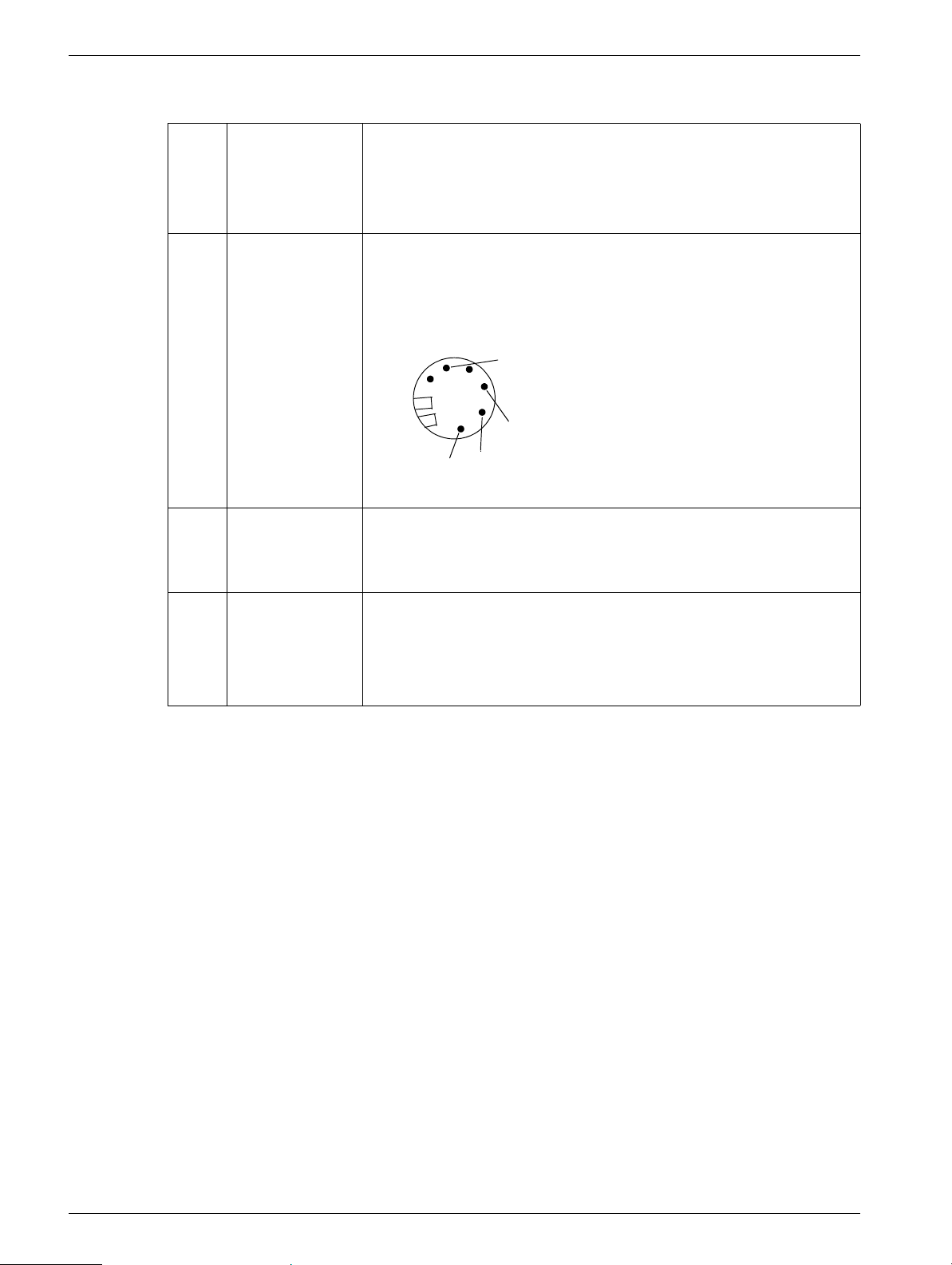
E92 Error Text: The two potentiometers have different values.
Possible
cause/action:
E93 Error Text: Erroneous US values.
Possible
cause/action:
Potentiometer skips.
Cable from potentiometer to board D3 ok?
Potentiometer defect?
5
Plug at US holder
Value between 1 -3 and 2-5
must be identical.
3
2
1
Dampness on the potentiometer.
C-MOS has lost values. Perform potentiometer adjustment
(Point "U" in the service menu).
Check default values (see SPL1-130.038.01...).
MODULARIS Uro Plus SPL1-130.840.02 Page 12 of 14 Siemens AG
Rev. 03 04.05 CS PS 24 Medical Solutions
Page 21

LITHOSTAR MODULARIS Error List 2 - 13
Displays on board D3 2
Once the system is turned on, different symbols are displayed chronologically on the display of board D3.
Display Possible cause/action
0 System o.k.
(only with the ultrasound localization option and if a communication was set
up to the ultrasound device.)
d Software download.
1 Data transfer, the decimal point is flashing.
4 The receiving file is being checked.
5 Software download time too long.
7 Everything o.k.
(only if no ultrasound localization option is available or if the ultrasound device
is turned off.)
- The service switch is set to normal mode - only for boards that still have no
software.
Text on the Console 2
"Chip card invalid" 2
This message is displayed when:
- the gold card is still logged on a different LITHOSTAR MODULARIS
- board D3 was replaced and the "init counter" on the gold card is already set at 3.
- the card is defective.
In normal mode, check whether the LED 174 on board D3 blinks temporarily and then
remains lit when turning it on.
LITHOSTAR MODULARIS SIEMENS 2
This message is displayed when too many errors occur. In this case, use the service PC
to generate an error log.
Missing Iso-center cross on the ultrasound system 2
There is no communication between the ultrasound system and the LITHOSTAR
MODULARIS.
Siemens AG SPL1-130.840.02 Page 13 of 14 MODULARIS Uro Plus
Medical Solutions Rev. 03 04.05 CS PS 24
Page 22

2 - 14 LITHOSTAR MODULARIS Error List
This page intentionally left blank.
MODULARIS Uro Plus SPL1-130.840.02 Page 14 of 14 Siemens AG
Rev. 03 04.05 CS PS 24 Medical Solutions
Page 23

Service software 3
(Hyper) Terminal program 3
The Windows program (Hyper) Terminal is used to retrieve error codes, settings, shock
wave counts, etc. from the LITHOSTAR MODULARIS and to save them to diskette.
The error log and therapy data can only be deleted from the CPU board using this (Hyper)
Terminal program.
This program is usually located under Accessories in WINDOWS.
The following provides a short overview of the connection procedure.
The standard cable (99 00 440 RE999) is used as the connection cable between the ser-
vice PC and the LITHOSTAR MODULARIS.
3 - 1
NOTE
In case of problems, use the Help function in the (Hyper) Terminal program.
The font "Courier New" is recommended for reading data stored on the diskette.
Due to the numerous versions and languages for WINDOWS, the
connection procedure is described in German and English.
Siemens AG SPL1-130.840.02 Page 1 of 18 MODULARIS Uro Plus
Medical Solutions Rev. 03 04.05 CS PS 24
Page 24

3 - 2 Service software
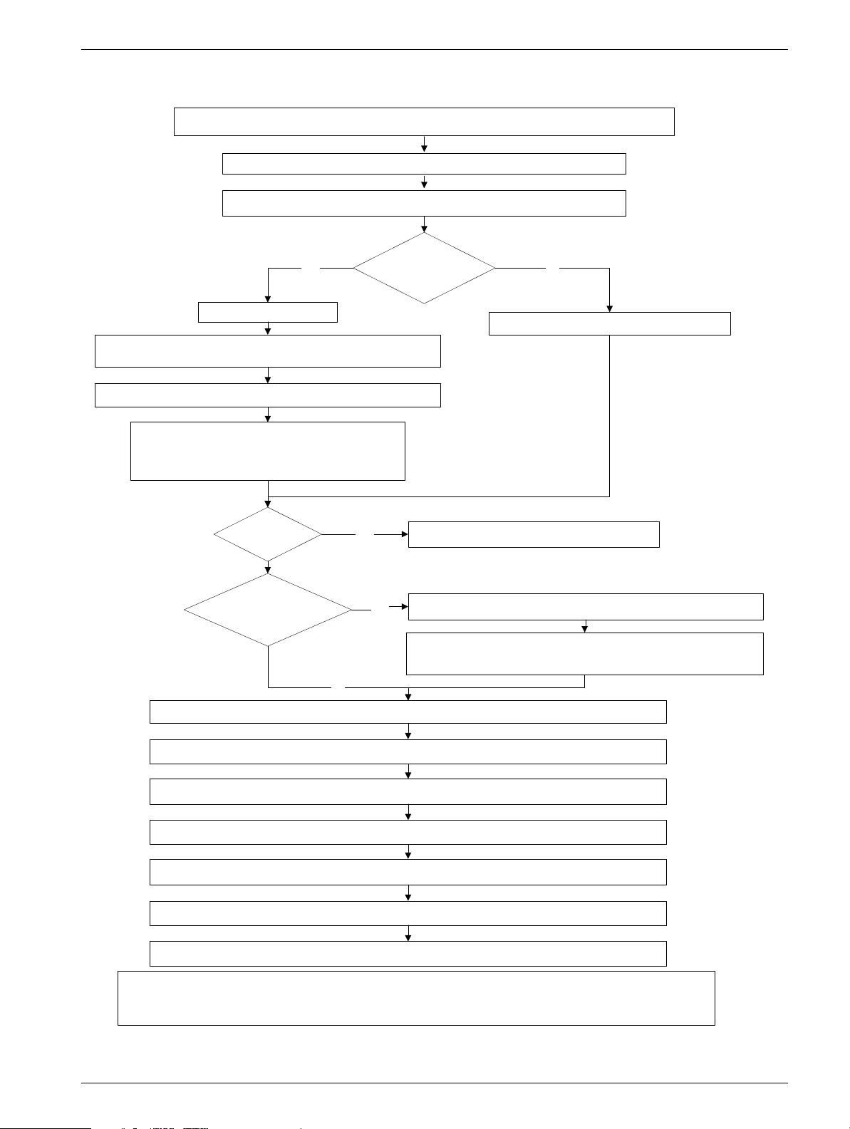
German WINDOWS 95 / 98 / NT 3
Generate and switch on connection between Service PC and the D3.X9 (com 3 Service) board
Open the Hyper Terminal Program (located under "Windows" - "Zubehör")
in LITHOSTAR MODULARIS
Set switch S2 on board D3 to service
First time
connection ?
Click on Hypterm.exe
In the window " Beschreibung der Verbindung"
for the name: enter Litho / for the icon: select one and click OK
In the window "Rufnummer", select, com1 or com2 for the
Enter the following settings in the window:
Parität: keine, Stopbits: 2 , Protokoll: kein and click OK
connection, and click OK
Bits pro sekunde: 9600, Daten bits: 8
1
New
board?
Save
the data to
drive a: or c:
Yes
No
Perform software download - page 3-13
Yes
Menu: Click on "Übertragung" and select "Text aufzeichnen"
In the window "Datei aufzeichnen" accept the file path indicated or
search for the desired file path with "Browse"... then click "Start"
NoYes
Open the connection, e.g. Litho
Press the "H" key, the text is displayed
Perform the desired tasks (refer to pages 3-4 to 3-10)
Then in the "Übertragung" Menu , select "Text aufzeichnen" and select "Beenden"
In the "Datei" menu, click on exit
Enter the appropriate response to the other queries
Set switch S2 on board D3 back to normal and remove the connection cable
End
*Additional information: In order to save the information from LITHOSTAR MODULARIS, it is best to save
the desired file as a text file. Basic procedure: open Windows Explorer. Open the folder, e.g. Temp, then click on
MODULARIS Uro Plus SPL1-130.840.02 Page 2 of 18 Siemens AG
Rev. 03 04.05 CS PS 24 Medical Solutions
the Datei menu and click "Neu / Textdatei". Enter the name for the text file.
Page 25
Service software 3 - 3
English Windows 95 / 98 / NT 3
Generate and switch on connection between Service PC and the D3.X9 (com 3 Service) board
Open the Hyper Terminal Program (located under "Windows" - "Accessories")
in LITHOSTAR MODULARIS
Set switch S2 on board D3 to service
First time
connection ?
Click on Hypterm.exe
for the name: enter Litho ; for the icon: select one and click OK
In the window "Connect To " select : com1 or com2 and click OK
In the window" Connection Description "
Enter the following settings in the window:
Bits per second: 9600, Data bits: 8, Parity: none,
Stop bits: 2, Flow control: None, and click OK
1
Save the data
to drive c: or a:
New
board?
Yes
Yes
NoYes
Open the existing connection, e.g. Litho.ht
Perform software download - page 3-13
In the Transfer menu, select Capture Text..*
In the window " Capture Text " accept the file path indicated or
search for the desired file path with Browse.. and click Start
No
Press the "H" key to display the text
Perform the desired tasks (refer to pages 3-4 to 3-10 )
Then in the Transfer menu, select Capture Text and select Stop
In the File menu, click Exit
Enter the appropriate response to the other queries
Set switch S2 on board D3 back to normal and remove the connection cable
End
*Additional Information: In order to save the information from LITHOSTAR MODULARIS, it is best to save the
desired file as a text file. Basic procedure: open Windows Explorer, open the folder e.g. Temp, then click on the
Siemens AG SPL1-130.840.02 Page 3 of 18 MODULARIS Uro Plus
Medical Solutions Rev. 03 04.05 CS PS 24
"File" menu and click on New / Text file and enter the name for the text file.
Page 26

3 - 4 Service software
Working with the Terminal program 3
Once you create a connection between the service PC and the LITHOSTAR
MODULARIS, press the "h" key to display the following text:
You will be notified if the software version is not compatible with the hardware version.
Refer to document SPL1-130.038.01... (Intranet) for default values.
--------------< SIEMENS LITHOSTAR MODULARIS >------------- software version: V_ _ _ hardware:_ _ - _ _
select option:
==============
h: show this help screen
p: show pulse counters
d: show diagnostic data
e: show error log 100 errors present
t: show therapy data
c: show chipcard data
a/b: adjust c-arm turn-back (a=-, b=+) now: 1200 ms
i: install/remove option ECG-trigger now: not installed
u: adjust ultrasound localization
r: set pulse rate now: variable 1/1.5/2 Hz
s: download new software
o: change orientation of treatment table. Now: ------ ----- : \_/ :
(X) = Physician's place for (X) : :
endourolog. therapy : :
---------------
The following will be displayed if the software version is not compatible with the hardware
version:
--------------< SIEMENS LITHOSTAR MODULARIS >------------- software version: V_ _ _ hardware:_ _ - _ _
** Error: software is not compatible with hardware and/or EPLD-version **
** System will not work ! Please download appropriate software. **
select option:
==============
h: show this help screen
p: show pulse counters
...
...
o: change orientation of treatment table. Now: ------ ----- : \_/ :
(X) = Physician's place for (X) : :
endourolog. therapy : :
---------------
MODULARIS Uro Plus SPL1-130.840.02 Page 4 of 18 Siemens AG
Rev. 03 04.05 CS PS 24 Medical Solutions
Page 27

Service software 3 - 5
select option: h 3
• Press the "h" key to display the input menu.
select option: p 3
• Press the "p" key to display the following text:
=> P
number of pulses:
system: 3627
(1) shock head: 3627
(2) capacitor: 3627
(3) spark gap: 3627
select 1..3 to delete pulse counter, any other key to abort
please note values or save to file before deleting data !
The total number of shock waves released are displayed.
The counters for the shock head / capacitor / spark gap can be reset to zero.
Always perform this procedure when replacing one of these parts, i. e. the "spark gap"
counter must be reset to zero if the charging unit is replaced.
select option: d 3
Press the "d" key to display the following text
Ö
D
'x'=exit
sensors HV P-bellow C-arm poti US poti1 US poti2
(C-grade) (V) (mV (mV) (mV) (mV)
24.15 23.97 20 756 5100 6300 6250
24.21 24.00 20 749 5100 6300 6250
sensors (C-grade) Displays the temperature at the shock wave head in celsius.
The difference between both temperature values may not exceed a
maximum of 3° C.
HV (V) Displays the voltage at the high-voltage capacitor.
If there is no connection to the charging unit (i.e. fiber optic cable
removed), the value is 20460.
P-bellow (mV) Displays the pressure in the coupling bellows.
P-automatic selected and rinse ended:
Q 500 mV – 2000 mV o.k.
C-arm pot (mV) Current voltage at the potentiometer for the angulation motor.
US poti1/2 (mV) Current voltage at the potentiometer for the US applicator. Accepta-
ble deviation: 50.
When US localisation is not available the value is 9995.
Siemens AG SPL1-130.840.02 Page 5 of 18 MODULARIS Uro Plus
Medical Solutions Rev. 03 04.05 CS PS 24
Page 28

3 - 6 Service software
select option: e 3
• Press the "e" key to display the following text:
=> E
no. date time err code 100 error messages:
100 02/04/1999 14:43.20 E00:
.
.
.
002 02/04/1999 09:18.36 E70:
001 02/04/1999 09:18.27 E70:
last watchdog-error code: 3F
-- end of errorlog --
press key 'D' to delete error log, any other key to abort
please save error log to file before deleting it !
- The number of errors present in the Errorlog is indicated (e.g. 100 error messages), as
in this case.
- The last 250 errors maximum are indicated; these are shown in blocks of 20.
Between these blocks is the line "press space to continue, "x" to exit".
- In order to have a better overview, with the code E00 the system powerup is shown.
- The oldest error has the number 1; the most recent error is all the way at the top.
- The line "last watchdog-error code" is internal information.
- The errors can only be deleted in the system after all error numbers have been viewed.
MODULARIS Uro Plus SPL1-130.840.02 Page 6 of 18 Siemens AG
Rev. 03 04.05 CS PS 24 Medical Solutions
Page 29

Service software 3 - 7
select option: t 3
• Press the "t" key to display the following text:
=> T
available data:
date (m/d/y) no. of patients
----------------------------- 03/01/1999 4
03/02/1999 4
03/03/1999 3
03/04/1999 3
03/05/1999 5
03/06/1999 5
03/07/1999 9
03/12/1999 7
enter 'A' to list all data: 40 patients, approx. 20 kByte of data
or
enter date of one file to read, press 'space' to stop display
format mm/dd/yyyy (x=exit):
Displays all days for which therapy data exists, as well as the number of patients.
To select the day: enter month/day/year.
The following data is displayed for each treatment (max 40):
- each increase in energy level
- the number of shock waves for each of the energy levels
(energy levels between 0.1 and 1.0 will be summarized in steps of 0.1)
- any errors that occurred
- the text output can be temporarily stopped at any time with the "Space" key.
Entering "A" is only recommended for saving all data to a diskette.
The data cannot be deleted until they have been read (on a workday).
Selecting delete will erase all therapy data.
Siemens AG SPL1-130.840.02 Page 7 of 18 MODULARIS Uro Plus
Medical Solutions Rev. 03 04.05 CS PS 24
Page 30

3 - 8 Service software
Content of Therapy log (selected day):
Patient no. 0001 start of therapy: 03/03/1999 17:03.15
---------- table of energy-level (*10) : pulses -----------
1:0012 ** E60: 32:0041 ** E60: -:.... -:.... -:.... -:.... -:.... -:....
-:.... -:.... -:.... -:.... -:.... -:.... -:.... -:.... -:.... -:....
-:.... -:.... -:.... -:.... -:.... -:.... -:.... -:.... -:.... -:....
-:.... -:.... -:.... -:.... -:.... -:.... -:.... -:.... -:.... -:....
End of therapy: 03/03/1999 17:03.24
Example:
- 1:0012 - 12 shock waves with an energy step between 0.1 and 1.0 (energy steps
between 0.1 and 1.0 are summarized in intervals of 0.1) released).
- **E60 - error 60 has occurred.
- 32:0041 - 41 shock waves with energy steps 3.2 released.
- **E60 - error 60 has occurred again.
---- end of therapy data ----
press key 'D' to delete all therapy data, any other key to abort
please save therapy data to file before deleting it !
Once all of the therapy data for a day is listed, the above text will be displayed. Press the
"d" key to delete all therapy data.
MODULARIS Uro Plus SPL1-130.840.02 Page 8 of 18 Siemens AG
Rev. 03 04.05 CS PS 24 Medical Solutions
Page 31

Service software 3 - 9
select option: c 3
• Press the "c" key to display the following text::
=> C
Card Data:
# Serial number Type -------< units >-------- eject-date/time pulse-count
GOLD init-cnt ... ... system
PPU on card int. from card
----------------------------------------------------------------------------- 1:
2:
3:53148300000000 G init=2 .... .... 04/13/1999 15:48.11 418
4:53149100000001 P 89956 0 0 04/13/1999 16:00.21 418
5:53148300000000 G init=3 .... .... 04/13/1999 16:40.51 418
6:53149100000001 P 84956 0 5000 04/13/1999 17:45.00 418
7:
8:
9:
10:53149100000001 P 84956 5000 0 card locked to unit ......
-- end of card data --
Text: 4: 531...0 G init=2 .... ..... 04/13 ... 418
Explan.: *1 *2 *3 *4 *5 *6 *7 *8
- *1: sequential number of the card inserted.
- *2: serial number of the card.
- *3: a "gold" card was inserted, i.e. the input slot is closed.
- *4: init-counter in the above example is init=2, i.e. the gold card was logged onto two
different D3 boards.
- *5: n.a.
- *6: n.a.:
Card ejected - *7: Date of ejection
- *8: System shock wave counter value when card ejected
Card in system - *7: Text: "Card locked to unit"
- *8: ............
Text: 5: 531...1 P 89956 0 0 04/13 ... 418
Explan.: *1 *2 *3 *4 *5 *6 *7 *8
- *1:sequential number of the card inserted
- *2: serial number of the card
- *3: a "pay per use" card was inserted
- *4: shock waves still present on the card
- *5: internal system card counter
- *6: number of shock waves registered on inserting the ppu card
Card ejected - *7: Date of ejection
- *8: System shock wave counter value when card ejected
Card in system - *7: Text: "Card locked to unit"
- *8: ............
Siemens AG SPL1-130.840.02 Page 9 of 18 MODULARIS Uro Plus
Medical Solutions Rev. 03 04.05 CS PS 24
Page 32

3 - 10 Service software
select option: a/b
NOTICE
You do not have to save changes
• Press the "a" key to reduce the time by 50 ms
i.e. from 1200 ms to 1150 ms.
• Press the "b" key to increase the time by 50 ms
i.e. from 1200 ms to 1250 ms.
In case of problems decoupling the angulation motor, the motor follow-on time for relaxing
the coupling can be changed.
Time < 300 and > 5000 cannot be selected.
select option: i 3
• Press the "i" key to display the following text:
=> I
are you sure to install optionECG-trigger ?
press '1' to confirm, any other key to abort
After pressing the "1" key and then the "h" key, display for "selection option i " reads "
now: installed".
select option: u 3
• Press the "u" key to display the following text:
=> U
---- submenu ultrasound adjust ----
to adjust marker position move applicator onto target
(see service instruction) and press key 'j'
actual value : _ _ _
change values for sector applicator - Press key 's'
change values for convex applicator - Press key 'c'
press key 'x' to exit
• If the potentiometer has to be adjusted (i.e. after board D3 is replaced or after the D3
ultrasound addition), then perform the following procedure:
• Push the probe receiver all the way to the front so that the space between the probe and
the iso-center phantom is very small when the iso-center phantom is raised.
• After pressing the "j" key, after "actual value: established value (max. 500) appears.
MODULARIS Uro Plus SPL1-130.840.02 Page 10 of 18 Siemens AG
Rev. 03 04.05 CS PS 24 Medical Solutions
Page 33

Service software 3 - 11
Convex
Sector
Array
Fig. 1 Fig. 2
CAUTION
change values for sector applicator - Press key 's'
change values for convex applicator - Press key 'c'
The following values can only be altered if approval is given by
Erlangen.
The correct values can be found in document SPL1-130.038.01..
(Intranet).
Explanation:
The displayed position (distance and position) of the objects on the ultrasound image is
calculated from the time difference between sending a signal and receiving the echo.
The standard speed of sound in the human body is 1540 m/sec, however, this speed can
vary depending on which tissue is being examined.
The position of the iso-center can be adjusted to ensure that the position of the cross matches the actual stone position on the ultrasound monitor.
This is possible with:
SECTOR APPLICATOR
---------------------------------------- actual values change with key (-) (+)
---------------------------------------- threshold value = 100 mm t T
scale low = 7.7 % l L
scale high = 7.7 % h H
Siemens AG SPL1-130.840.02 Page 11 of 18 MODULARIS Uro Plus
Medical Solutions Rev. 03 04.05 CS PS 24
Page 34

3 - 12 Service software
CONVEX APPLICATOR
---------------------------------------- actual values change with key (-) (+)
---------------------------------------- threshold value = 100 mm t T
scale low = 7.7 % l L
scale high = 7.7 % h H
Every probe can be set to one of three settings:
threshold value
The point at which the "scale high" value is used (default 100 mm).
fig. 2
scale low
fig. 2
scale high
fig. 2
Correction factor (default 7.7 %) between 0 mm and the "threshold
value " (This value is useful for thin patients).
Correction factor (default 7.7 %) between "threshold value " and end
(This value is useful for obese patients.).
By selecting the keys "t, l, h " (depending on application) the value is reduced; select T, L,
H to increase the value.
select option: r 3
• Press the "r" key to change the "pulse rate"
Selection: fixed 2 Hz (USA) or variable 1/1.5 /2 Hz
After pressing the "h" key, display for "selection option r" shows the pulse rate set.
select option: s 3
CAUTION
Software download.
If not observed, D3 board can be damaged.
The system and service PC must not be turned off during a software download. If this occurs, board D3 must be replaced.
Software downloads are possible only if the software and hardware are compatible.
• Press the "s" key to display the following text:
=> S
press key '1' to confirm download, any other key to abort
After "1" has been entered, the software download must start within 60 seconds.
If the 60 seconds elapses without starting the download, reselect "h" from the entry menu,
reselect "s", etc.
Once the software download is complete, check that the values in the "ultrasound localization" menu for the applicators are identical to those in document SPL1-130.038.01..
(Intranet). If this is not the case, make the appropriate changes.
MODULARIS Uro Plus SPL1-130.840.02 Page 12 of 18 Siemens AG
Rev. 03 04.05 CS PS 24 Medical Solutions
Page 35

Service software 3 - 13
Software download with Windows 95 / 98 / NT 3
Do not select "capture text file" when downloading the software.
Log on, as described on page 3-2 or 3-3
Insert the diskette containing the software into drive A
Press the "s" key and then press "1"
German Windows: English Windows:
In the "Übertragung" menu, select ... Datei senden
In the "Datei senden" window: Dateiname: click
"Durchsuchen"; select the file with the "bin" extension
on the diskette inserted (Laufwerk beachten)
Protokoll: select Xmodem . Click Senden
No
During the data transfer, "1" is displayed on board D3 and the decimal point flashes.
After the transfer, a test is executed. ("2" is displayed on board D3; "0" or "7" when complete.)
In the "Transfer" menu, select ... Send File
In the "Send File" window: File name: click
"Browse"; select the file with the "bin" extension on
the diskette inserted. (observe drive)
Protocol: select Xmodem . Click Send
Disregard the error messages
Switch the system off / on
Press the "h" key to display the text
Is correct software
version displayed?
Press the "n" key and
enter the name
Check the system-specific settings (language, ECG triggering, pulse rate and table)
Siemens AG SPL1-130.840.02 Page 13 of 18 MODULARIS Uro Plus
Medical Solutions Rev. 03 04.05 CS PS 24
Yes
Set the date and time. Check Ultrasound default values.
For additional procedures, refer to pages 3-2 or 3-3
Was software
transferred to a new
D3 board?
No
Page 36

3 - 14 Service software
select option: 0 3
• Press the "o" key to switch from the right side to the left side of the table.
This may only be done if the table has also been mechanically modified, refer to
MODULARIS Uro Installation and Start-up instructions.
After pressing the "h" key, the display for "selection option o" will show which table was
selected.
Delivery configuration is right table (Fig. 3).
Left table
o: change orientation of treatment table. Now: ------ ----- : \_/ :
(X) = Physician's place for : : (X)
endourolog. therapy : :
---------------
Right table
o: change orientation of treatment table. Now: ------ ----- : \_/ :
(X) = Physician's place for (X) : :
endourolog. therapy : :
---------------
Fig. 3
A
B
D
C
C
D
B
Left side version
Right side versionA
MODULARIS Uro Plus SPL1-130.840.02 Page 14 of 18 Siemens AG
Rev. 03 04.05 CS PS 24 Medical Solutions
Page 37

Service software 3 - 15
Text after replacing board D3 3
• Press the "h" key to display the following text (the software is installed).
--------------< xxxxxxx Lithomodule >--------------
------------------------------------------ n: select system name before shipping !
------------------------------------------ software version: V_ _ _ hardware:_ _ - _ _
select option:
==============
h: show this help screen
p: show pulse counters
...
...
...
o: change orientation of treatment table. Now: ------ ----- : \_/ :
(X) = Physician's place for (X) : :
endourolog. therapy : :
---------------
• Press the "n" key to display the following text
=> N
select number to define system name:
1: SIEMENS
2: OEM-customer
• Press 1 or 2 and follow the instructions.
you selected: SIEMENS
press 'C' to confirm, any other key to abort
SIEMENS
CAUTION
Siemens AG SPL1-130.840.02 Page 15 of 18 MODULARIS Uro Plus
Medical Solutions Rev. 03 04.05 CS PS 24
This procedure cannot be undone.
Page 38

3 - 16 Service software
LITHOSTAR MODULARIS control panel 3
S2S1
Display
Normal mode
The function is explained in
the operating instructions
Initialization
automatic
Therapy menu
(therapy data is
displayed)
S3
S4
Fig. 4
Service mode
Switch S2 on D3 set
to service
The text in service mode is
always
Therapy menu
(therapy data is
in English
Initialization
automatic
displayed)
S5
S6
S2 activated
Selection menu
Orientation
Pulse s/m in
ECG triggering
P-regulation
S4 activated
Chip card *
Rinse
Brightness
* with "pay per use" option only
MODULARIS Uro Plus SPL1-130.840.02 Page 16 of 18 Siemens AG
Rev. 03 04.05 CS PS 24 Medical Solutions
S2 activated
Selection
Orientation
Pulse s/m in
ECG triggering
P-regulation
S4 activated
Chip card
Rinse
Brightness
Service
Page 39

Service software 3 - 17
The information in the Service and Chip card menus is displayed in English only
The information in the Service and Chip card menus is displayed in English only
The information in the Service and Chip card menus is displayed in English only
Chip card
Chip card
Chip card
Rinse
Rinse
Rinse
Brightness
Brightness
Brightness
Service
Service
Service
Selectable by activating the S2 key (Continue)
Selectable by activating the S2 key (Continue)
Selectable by activating the S2 key (Continue)
Service
Service
Chip card
Chip card
Chip card
Display Gold card counter
Display Gold card counter
Display Gold card counter
status
status
status
Set clock
Set clock
Set clock
Selectable by activating the S3/S4 keys
Selectable by activating the S3/S4 keys
Selectable by activating the S3/S4 keys
Cooling unit Coupling circuit System data
Cooling unit Coupling circuit System data
Cooling unit Coupling circuit System data
Service
Set clock
Set clock
Set clock
Cooling unit
Cooling unit
Cooling unit
Coupling circuit
Coupling circuit
Coupling circuit
System data
System data
System data
Press S2 (Continue)
Adjust S2 (Continue)
Adjust S2 (Continue)
Adjust S2 (Continue)
Set clock
Set clock
Set clock
month
month
month
day
day
day
year
year
year
hour
hour
hour
minute
minute
minute
S3/S4 Selection
S3/S4 Selection
S3/S4 Selection
S5/S6 Change
S5/S6 Change
S5/S6 Change
S2 End (Return)
S2 End (Return)
S2 End (Return)
Press S2 (Continue)
Press S2 (Continue)
Adjust S2 (Continue)
Adjust S2 (Continue)
Adjust S2 (Continue)
Error table
Error table
Error table
E.. : .........
E.. : .........
E.. : .........
E.. : .........
E.. : .........
E.. : .........
E.. : .........
E.. : .........
E.. : .........
E.. : .........
E.. : .........
E.. : .........
S3/S4 Selection
S3/S4 Selection
S3/S4 Selection
S2 (help) more info
S2 (help) more info
S2 (help) more info
S1 (Return)
S1 (Return)
S1 (Return)
S5/S6
S5/S6
S5/S6
fill / empty
fill / empty
fill / empty
S2
S2
S2
Return
Return
Return
English
English
English
German
German
Language:
Language:
Language:
Select the language
Select the language
Select the language
desired with S5/S6
desired with S5/S6
desired with S5/S6
S2 Return (end)
S2 Return (end)
S2 Return (end)
German
Spanish
Spanish
Spanish
French
French
French
S5/S6
S5/S6
S5/S6
fill / empty
fill / empty
fill / empty
S2
S2
S2
Return
Return
Return
Pulse counter C-arm 0° pos. SW: V...... / V.....Error table
Pulse counter C-arm 0° pos. SW: V...... / V.....Error table
Pulse counter C-arm 0° pos. SW: V...... / V.....Error table
Press S2 (Continue)
Press S2 (Continue)
Adjust S2 (Continue)
Adjust S2 (Continue)
Adjust S2 (Continue)
Press S2 (Continue)
Pulse counter
Pulse counter
Pulse counter
system unit:
system unit:
system unit:
shock head:
shock head:
shock head:
capacitor:
capacitor:
capacitor:
spark gap:
spark gap:
spark gap:
Reset counter
Reset counter
Reset counter
S3/S4 selection
S3/S4 selection
S3/S4 selection
S2 (reset)
S2 (reset)
S2 (reset)
S1 (yes)
S1 (yes)
S1 (yes)
S2 (no)
S2 (no)
S2 (no)
Press S2 (continue
Adjust S2 (Continue)
Adjust S2 (Continue)
Adjust S2 (Continue)
System Data
System Data
System Data
Error table
Error table
Error table
Language
Language
Language
Puls e counter
Puls e counter
Puls e counter
C-arm 0° pos.
C-arm 0° pos.
C-arm 0° pos.
SW: V...... / V.....
SW: V...... / V.....
SW: V...... / V.....
Adjust (S2)
Adjust (S2)
Adjust (S2)
Press adjust (S2)
Press adjust (S2)
Move the C-arm
Move the C-arm
Move the C-arm
to 0° with the keys
to 0° with the keys
to 0° with the keys
on the operating
on the operating
on the operating
panel
panel
panel
OK - activate (S1)
OK - activate (S1)
OK - activate (S1)
(Movement is
(Movement is
(Movement is
slower than in the
slower than in the
slower than in the
normal mode)
normal mode)
normal mode)
Display the
Display the
Display the
current software
current software
current software
1:
1:
1:
system
system
system
2:
2:
2:
operating unit
operating unit
operating unit
Siemens AG SPL1-130.840.02 Page 17 of 18 MODULARIS Uro Plus
Medical Solutions Rev. 03 04.05 CS PS 24
Page 40

3 - 18 Service software
This page intentionally left blank.
MODULARIS Uro Plus SPL1-130.840.02 Page 18 of 18 Siemens AG
Rev. 03 04.05 CS PS 24 Medical Solutions
Page 41

LITHOSTAR MODULARIS 4
LITHOSTAR MODULARIS Parts overview 4
4 - 1
Assembly
Function Item number
Shock wave head C
Shock wave head
C plus
Coupling bellow C 47 78 705 The clamping strap 70 56 823 must be ordered
Coupl. bellow C plus 70 41 416 The clamping strap 70 61 013 must be ordered
High voltage cable 11 81 523 Refer to description "cables in corrugated tubing"
High voltage connec-
tor
Charging unit 55 31 046 Refer to description
Charging unit HLS 11 58 000 Replaces charging unit with spark gap 55 31 046
Cooling unit 47 78 002 Refer to description
16 11 008
70 41 358
11 81 622 Refer to description
Refer to description
Replace the water
Also replace the M1 pump head
Reset the counter to zero
SW head C is delivered without the coupling bel-
low, SW head C plus with coupling bellow
separately!
separately
Fill in the "dates of start up" field.
Comments on replacement
Pump 47 73 847
70 41 101
Temperature sensor 55 31 277 Refer to description "cables in corrugated tubing"
Pressure sensor 55 31 243 Refer to description "cables in corrugated tubing"
Board D3 55 31 053 Refer to description
Battery for board D3 31 46 073
Control unit 55 31 129 No special instructions required
Transformer and
board D1
Power supply board D155 31 301 Check fuses
Angulation motor 55 31 392 Refer to description
MODULARIS sup-
port arm
Rotary joint lock 55 31 608 Refer to description
Potentiometer 70 50 433 Refer to description
55 31 111 Note jumpers for the line voltage
55 31 020 Refer to description
Coupling pump; Refer to description
Cooling pump; Refer to description
Perform a function test following replacement
230 V: 3 -5, 200V: 2 - 6, 120 V:1 - 5 and 4 - 7,
100 V: 1 -6 and 2 - 7
SIREMOBIL switch 10 70 721 Refer to description
Iso-center phantom 47 78 754 Refer to description
Siemens AG SPL1-130.840.02 Page 1 of 34 MODULARIS Uro Plus
Medical Solutions Rev. 03 04.05 CS PS 24
Page 42

4 - 2 LITHOSTAR MODULARIS
I
Fig. 1 Fig. 2
Shock wave head 4
Shock wave head covers 4
• Switch the system off. Remove the covers on the system unit by removing the screws.
• Remove the water reserve tank and drain the remaining water.
• Reinstall the water reserve tank.
• Switch the system on. Position the support arm in the horizontal position.
• Set service switch S2 on board D3 to position 2 (service on).
• Select "service" on the control unit and then "coupling circuit".
• Activate the corresponding key for "empty" (S6) on the control unit until the coupling
bellow is located next to the lens.
• Switch the system off.
• Only the equipment with ultrasound localization:
- Unscrew the two placement parts for the ultrasound.
- Ensure that the screw lengths are correct when tightening them.
• Remove the mounting screws (I/Fig. 2) for the upper cover on both sides of the shock
head.
• Push the buttons in the direction of the arrow on both sides of the iso-center phantom
(Fig. 2) and at the same time flip the iso-center phantom back (Fig. 1).
• Detach the upper cover, removing it toward the front.
• Push the buttons on both sides of the iso-center phantom in the direction of the arrow
(Fig. 1) and at the same time flip the iso-center phantom up (Fig. 2).
• If required, remove the 3 cover screws from both lower covers and remove the covers.
• Reattach the covers in the reverse order after completion of all work.
MODULARIS Uro Plus SPL1-130.840.02 Page 2 of 34 Siemens AG
Rev. 03 04.05 CS PS 24 Medical Solutions
Page 43

LITHOSTAR MODULARIS 4 - 3
1
2
V
1
V
U
Fig. 3 Fig. 4
Removing the shock wave head 4
System configuration
n = several
Replace
shock wave
head
1 LITHOSTAR MODULARIS
and
1 SIREMOBIL Iso-C
To support arm S0050
Adjustment of iso-center on the shock
wave head; refer to chapter "Iso-center with X-ray - to support arm serial
number 0050".
From support arm S0051
Adjustment of iso-center on the
SIREMOBIL Iso-C; refer to chapter
"Iso-center with X-ray - from support
arm serial number 0051".
1 LITHOSTAR MODULARIS
and
n SIREMOBIL Iso-C
It is important to follow this workflow to
avoid having to readjust the iso-center on all
SIREMOBILE!
• Prior to replacing the shock wave head, view
the iso-center (the three C-arm positions) and
if possible, save it or make a hardcopy.
• Replace shock wave head.
• Check iso-center; the setting must be
identical to that of the defective shock wave
head.
If an adjustment is necessary, it must be made
via the shock wave head setting; refer to
chapter "Iso-center with X-ray - to support
arm serial number 0050".
• Remove the covers of the shock wave head (refer to "Shock wave head covers").
• Remove the coupling bellows, carefully pulling the small pin out of the air suction hose
inside the coupling bellows (refer also to Fig. 8 and Fig. 9).
• Loosen the four screws (V/Fig. 3) on the iso-center phantom using an Allen key with a
guide pin, but do not remove them.
• Flip the iso-center phantom toward the front and completely remove it (this may be
difficult).
- If the iso-center phantom has a serial number (2/Fig. 3) it can be removed by using two
screw pulleys (1/Fig. 3) on the shock wave head.
Siemens AG SPL1-130.840.02 Page 3 of 34 MODULARIS Uro Plus
Medical Solutions Rev. 03 04.05 CS PS 24
Page 44

4 - 4 LITHOSTAR MODULARIS
• Open valve Y8(Fig. 10, 11),
i.e. switch the Y8 lever from horizontal = closed to vertical = open.
• Switch the system on.
• Set service switch S2 on board D3 to position 2 (service on).
• Select "service" on the control unit and then "cooling unit".
• Activate the corresponding key for "empty" on the control unit until no more water flows
out.
• Adjust service switch S2 on board D3 to position 1 (service off).
• Switch the system off.
• Remove the 2 Allen screws (U/Fig. 4) underneath the shock wave head.
• Remove the screw (SL/Fig. 7) with the protective conductor on the shock wave head.
• Wait at least 10 minutes after switching the system off. Then push the high-voltage
connector downward, until the openings (O/Fig. 7) are free.
• Loosen the Allen screws in the openings (O/Fig. 7) but do not remove them.
• Disconnect all the water hoses at both interfaces of the shock wave head.
• Remove the shock wave head toward the front.
NOTICE
There may be water remaining in the shock wave head.
MODULARIS Uro Plus SPL1-130.840.02 Page 4 of 34 Siemens AG
Rev. 03 04.05 CS PS 24 Medical Solutions
Page 45

LITHOSTAR MODULARIS 4 - 5
48 ±1 mm
Fig. 5
T
Fig. 6 Fig. 7
Installing the shock wave head 4
• Shorten both hoses at the shock wave head corresponding to the dimensions in Fig. 5.
• Check that the spring-mounted temperature sensor (T/Fig. 6) is seated correctly in the
groove.
• Insert the air suction hose centrally through the shock wave head (L/Fig. 9).
• Install the new shock wave head from above and insert the water hoses;
when doing this ensure that the hose marked in red (R/Fig. 7) is located next to the
high-voltage connector and that the air suction hose underneath the shock wave
head is neither kinked nor caught in the shock wave head.
• Attach the shock wave head with the Allen screws (O/Fig. 7) visible through the opening.
• Push the high-voltage plug as far up as possible, until the openings (O/Fig. 7) are
covered again.
SL
O
R
• Reattach the screw (SL/Fig. 7) with the protective conductor.
• Retighten the 2 Allen screws (U/Fig. 4) underneath the shock wave head.
• Place the iso-center phantom on top so that it is flush and secure it with the four screws
(V/Fig. 3) (use an Allen key with a guide pin for this purpose).
Siemens AG SPL1-130.840.02 Page 5 of 34 MODULARIS Uro Plus
Medical Solutions Rev. 03 04.05 CS PS 24
Page 46

4 - 6 LITHOSTAR MODULARIS
ST
ST
L
L
Fig. 8 Fig. 9
• Insert the air suction hose (L) as shown in Fig. 8 and Fig. 9 carefully over the pin (ST) in
the coupling bellows. Tie a knot to secure it (Fig. 8).
• Install the coupling bellows; when doing this, ensure that the pin (ST/Fig. 9) for
attachment of the hose is positioned at the highest point and is seated correctly in the
clamp.
• Replace the hose pump head for cooling pump M1 (refer to the section "Hose pump
head in the coupling circuit"). (Not necessary if IWAKI pump installed).
• Fill the cooling circuit (refer to the section "Filling the cooling circuit").
• Fill the coupling circuit (refer to the section "Filling the coupling circuit").
• Check the iso-center as described in chapter 5.
• Select "service" and then "coupling circuit" on the control unit.
• Activate the corresponding key for "empty" (S6) on the control unit until the coupling
bellows is located next to the lens.
• Reinstall the covers of the shock wave head according to the procedure for removal.
• Adjust service switch S2 on board D3 to position 1 (service off).
• Select "rinse" on the control unit and activate the cycle (ends automatically).
• Read out the counter for the shock wave head and record the value in the operating
protocol (in Register 4).
• Reset the counter (refer to chapter 3).
• Connect the service PC to the board as described in chapter 3.
• Read out both temperature values on the service PC; the difference must not exceed a
maximum of 3° C.
• Release shock waves: both temperature values should increase closely in parallel
(∆Τ <
3° C).
• Reattach the system cover.
• Perform a function test.
MODULARIS Uro Plus SPL1-130.840.02 Page 6 of 34 Siemens AG
Rev. 03 04.05 CS PS 24 Medical Solutions
Page 47

LITHOSTAR MODULARIS 4 - 7
Replace isocenter phantom 4
System configuration
n = several
Replace isocenter phantom
1 LITHOSTAR MODULARIS
and
1 SIREMOBIL Iso-C
To support arm S0050
Adjustment of iso-center on the shock
wave head; refer to chapter "Iso-center with X-ray - to support arm serial
number 0050".
From support arm S0051
Adjustment of iso-center on the
SIREMOBIL Iso-C; refer to chapter
"Iso-center with X-ray - from support
arm serial number 0051".
1 LITHOSTAR MODULARIS
and
n SIREMOBIL Iso-C
It is important to follow this workflow to
avoid having to readjust the iso-center on all
SIREMOBILE!
• Prior to replacing the iso-center phantom,
view the iso-center (the three C-arm
positions) and if possible, save it or make a
hardcopy.
• Replace the iso-center phantom.
• Check iso-center; the setting must be
identical to that of the defective iso-center
phantom.
If an adjustment is necessary, it must be made
via the shock wave head setting; refer to
chapter "Iso-center with X-ray - to support
arm serial number 0050".
Siemens AG SPL1-130.840.02 Page 7 of 34 MODULARIS Uro Plus
Medical Solutions Rev. 03 04.05 CS PS 24
Page 48

4 - 8 LITHOSTAR MODULARIS
Filling limit
Filling limit
2
Valve Y8
Valv e Y8
1 1
Fig. 10 Fig. 11
K
3
1
Fig. 12
Cooling unit 4
Checking the cooling unit 4
• Disconnect both cables at the temperature switch B1 (located on the cooling unit
underneath board D3 and the fiber optic connections).
• Connect both cables together.
• Switch the system on.
• The ventilator and compressor in the cooling unit start up - if not, check the power supply
- if o.k., replace cooling unit.
• Switch the system off.
• Reconnect both cables.
MODULARIS Uro Plus SPL1-130.840.02 Page 8 of 34 Siemens AG
Rev. 03 04.05 CS PS 24 Medical Solutions
Page 49

LITHOSTAR MODULARIS 4 - 9
Replacing the cooling unit 4
• Empty the coupling circuit and cooling circuit according to the instructions.
• Replace the cooling unit.
• Fill the coupling circuit and cooling circuit according to the instructions.
• Complete the " Date of start up" field on the cooling unit label.
Filling the cooling circuit 4
• Remove the system covers.
• Fill the water reserve tank with distilled water.
• Switch the system on.
• Position the support arm in the horizontal position.
• Open the degassing valve (cap K/Fig. 12) in the cooling unit by two turns (it should
remain open).
• Adjust service switch S2 on board D3 to position 2 (service on).
• Open valve Y8 (Fig. 10/11),
i.e. switch the Y8 lever from horizontal = closed to vertical = open.
• Select "service" on the control unit and then "cooling unit".
• Activate the corresponding key for "fill" on the control unit until the water flowing from the
return line in the water reserve tank is free of air bubbles.
(hose pump M1 will run as long as required, V188 glows on board D3).
• Close valve Y8 (Fig. 10/11);
i.e. switch the Y8 lever from vertical - open to horizontal = closed.
• Adjust service switch S2 on board D3 to position 1 (service off).
• Switch the system off.
• Reattach the system covers.
Filling the coupling circuit 4
• Remove the system covers.
• Fill the water reserve tank with distilled water, if necessary.
• Switch the system on and position the support arm in the horizontal position
• Adjust service switch S2 on board D3 to position 2 (service on).
• Select "service" on the control unit and then "coupling circuit".
• Activate the corresponding key for "fill" (S6) on the control unit until the coupling bellows
rounds out slightly.
• Check whether the air suction hose inside the coupling bellows is actually secured at the
topmost position (refer to the section "Installing the shock wave head" and Fig. 8).
• Adjust service switch S2 on board D3 to position 1 (service off).
• Select "rinse" on the control unit and activate the cycle; this function ends automatically.
Siemens AG SPL1-130.840.02 Page 9 of 34 MODULARIS Uro Plus
Medical Solutions Rev. 03 04.05 CS PS 24
Page 50

4 - 10 LITHOSTAR MODULARIS
• If air bubbles are visible in the coupling bellows, start the "rinse" cycle again.
• Switch service switch S2 on board D3 to position 2 (service on).
• Select "service" and then "coupling circuit" on the control unit.
• Activate the corresponding key for "empty" (S6/Fig. 4/page 3-16) on the control unit until
the coup-ling bellows is located next to the lens.
• Switch the system off.
• Fill the water reserve tank up to the fill line (Fig.10/ 11) with distilled water.
• Set service switch S2 on board D3 to position 1 (service off).
• Switch the system on. The "rinse" cycle will be activated automatically and the coupling
bellows will fill.
• Switch the system off.
• Fill the water reserve tank with distilled water.
• Reattach the system covers.
Emptying the cooling circuit with the old pump (2/Fig. 10) 4
• Remove the system covers.
• Remove the water reserve tank and empty the water.
• Insert the return hose into the water reserve tank.
• Position the support arm in the horizontal position.
• Open valve Y8 (Fig. 10),
i.e. switch the Y8 lever from horizontal = closed to vertical = open.
• Switch the system on.
• Adjust service switch S2 on board D3 to position 2 (service on).
• Select "service" on the control unit and then "cooling unit".
• Activate the corresponding key for "empty" on the control unit until no more water flows.
• Adjust service switch S2 on board D3 to position 1 (service off).
• Switch the system off.
MODULARIS Uro Plus SPL1-130.840.02 Page 10 of 34 Siemens AG
Rev. 03 04.05 CS PS 24 Medical Solutions
Page 51

LITHOSTAR MODULARIS 4 - 11
Emptying the cooling circuit with the new pump (3/Fig. 11) 4
• Remove the system covers from the basic unit.
• Remove the water reserve tank and empty the water.
• Insert the return hose into the water reserve tank.
• Position the support arm in the horizontal position.
• Open valve Y8 (Fig. 11),
i.e. switch the Y8 lever from horizontal = closed to vertical = open.
• Exchange the two water connections on the cooling pump. (The two black-marked hoses
are not connected).
• Switch the system on.
• Set service switch S2 on board D3 to position 2 (service on).
• Select "service" and then "cooling unit" on the control unit.
• Activate the corresponding key for "empty" on the control unit until the water stops.
• Set service switch S2 on board D3 to position 2 (service off).
• Switch the system off.
• Properly connect the two water connections to the cooling pump. (Both black-marked
hoses must be reconnected).
Emptying the coupling circuit 4
• Remove the system covers on the basic unit.
• Remove the water reserve tank and empty the water.
• Switch the system on.
• Position the support arm in the horizontal position.
• Set service switch S2 on board D3 to position 2 (service on).
• Select "service" and then "coupling circuit" on the control unit.
• Activate the corresponding key for "empty" (S6/Fig. 4/ page 3-16) on the control unit until
the coupling bellows is located next to the lens.
• Switch the system off.
Siemens AG SPL1-130.840.02 Page 11 of 34 MODULARIS Uro Plus
Medical Solutions Rev. 03 04.05 CS PS 24
Page 52

4 - 12 LITHOSTAR MODULARIS
Hose pump head in the coupling circuit 4
Removing the hose pump head 4
• Remove the system cover and the cover of the shock wave head.
• Empty the coupling circuit (refer to the section "Emptying the coupling circuit").
• Switch the system off.
• Remove the safety latch on the hose pump head.
• Press the black lock (1/Fig. 10/11) upward or downward and remove the hose pump
head from the drive.
• Open the 2 hose clamps and remove the hoses.
• Remove the hose pump head.
Installing the hose pump head 4
• Place the hose pump head on the drive shaft and lock into place.
• Reconnect the 2 hoses with the hose clamps.
Ensure that the hoses are the correct length, i.e. cut them to the same length as the old
hoses.
• Fill the coupling circuit (refer to "Filling the coupling circuit").
Hose pump head in the cooling circuit 4
Removing the hose pump head 4
• Switch the system off.
• Open the system cover.
• Empty the cooling circuit (refer to the section "Emptying the cooling circuit").
• Remove the safety latch on the hose pump head.
• Press the black lock (1/Fig. 10) downward or upward and remove the hose pump head
from the drive.
• Open the 2 hose clamps and disconnect the hoses.
• Remove the hose pump head.
Installing the hose pump head 4
• Place the hose pump head on the drive shaft and lock into position.
• Reconnect the 2 hoses with the hose clamps.
Ensure that the hoses are the correct length, i.e. cut them to the same length as the old
hoses.
• Fill the cooling circuit (refer to the section "Filling the cooling circuit").
MODULARIS Uro Plus SPL1-130.840.02 Page 12 of 34 Siemens AG
Rev. 03 04.05 CS PS 24 Medical Solutions
Page 53

LITHOSTAR MODULARIS 4 - 13
IWAKI cooling pump 4
Removal 4
• Switch the system off.
• Open the system cover.
• Remove the fasteners on the pump.
• Remove the motor connections on the terminal block.
• Loosen the screws to remove the pump.
Installation 4
• Tighten the pump.
• Connect the motor connections.
• Connect the fasteners on the pump (The black-marked water hoses must be connected).
• Fill the cooling circuit (refer to the section "Filling the cooling circuit").
Siemens AG SPL1-130.840.02 Page 13 of 34 MODULARIS Uro Plus
Medical Solutions Rev. 03 04.05 CS PS 24
Page 54

4 - 14 LITHOSTAR MODULARIS
SL
HK
N
Fig. 13 Fig. 14
Charging unit
IS
NOTICE
The charging unit should not be opened again.
If a charging unit with spark gap is replaced by a charging unit
with semiconductor switch (11 58 000), then the software VA00J
must be used.
• Switch the system off, disconnect the power plug.
• Remove the covers (of the basic system unit), disconnect the charging unit power cable.
• Wait at least 10 minutes after switching the system of. Then remove the cover on
the back high-voltage cable connection (Fig. 13).
• Remove the high voltage cable (HK/Fig. 13) and the protective conductor (SL/Fig. 13) by
removing the screws.
• Remove the fiber optic cable from the charging unit.
• Remove the six Allen screws (IS/Fig. 14) (three on each side, right and left).
• Remove the old charging unit from the basic system unit and install the new one.
• Reattach the six Allen screws (IS/Fig. 14) and tighten them (three on each side, right and
left).
• Reconnect the fiber optic cable to the charging unit (check for correct connections).
• Reattach the protective conductor and the high-voltage cable with the screws (Fig. 13).
• Reattach the cover on the high-voltage cable connection.
• Reconnect the power cable of the charging unit.
• Record the installation date on the charging unit (next to the capacitor).
• Switch the system on, read out the counters for the charging unit and the spark gap and
record the values on the old charging unit. Reset the counter (refer to chapter 3).
• Perform a function test.
• Switch the system off and reattach the system cover.
MODULARIS Uro Plus SPL1-130.840.02 Page 14 of 34 Siemens AG
Rev. 03 04.05 CS PS 24 Medical Solutions
Page 55

LITHOSTAR MODULARIS 4 - 15
G
D
S
G
Fig. 15 Fig. 16 Fig. 17
High voltage connector 4
• Remove the covers of the basic system unit and the shock wave head.
• Remove the shock wave head (refer to the corresponding section).
• Remove the cover at the charging unit above the high-voltage connection by removing
the screws (Fig. 13).
M
KS
• Remove the three clamps (N/Fig. 13) on the high-voltage connection.
• Push the high voltage cable (HK/Fig. 16) in the direction of the shock wave head through
the corrugated tubing until the high-voltage connector is accessible (Fig. 15).
• Remove the screws (S/Fig. 15) on the high voltage connector.
• Push the metal housing (G/Fig. 16) above the high-voltage plug toward the back.
• Open the cover (D/Fig. 16) of the high-voltage connector.
• Remove the connection clamps (M/Fig. 17) in the old high-voltage connector.
• Open the cable clamps (KS/Fig. 17) of the high-voltage connector.
• Connect the new high-voltage connector; reconnect and secure it in the reverse order of
the removal.
• Push the high-voltage cable back in the direction of the charging unit (in the basic unit)
and connect it (Fig. 13).
• Mount the shock wave head assembly (refer to the corresponding section).
• Attach all covers (refer to the corresponding sections).
Siemens AG SPL1-130.840.02 Page 15 of 34 MODULARIS Uro Plus
Medical Solutions Rev. 03 04.05 CS PS 24
Page 56

4 - 16 LITHOSTAR MODULARIS
T
W
T
x
Tp
Fig. 18 Fig. 19 Fig. 20
KB
Cables in the corrugated tubing
NOTICE
• Remove the covers on the basic system unit and the shock wave head.
• Remove the shock wave head (refer to the corresponding section).
• Push the temperature sensor slightly forward (T/Fig. 18) in the shock wave head support
and then push it back to the side.
• Secure the spiral spring to the sensor supply cable approx. 4 cm (x/Fig. 19) behind the
temperature sensor with adhesive tape to keep it from slipping back (KB/Fig. 19).
All cables must be disconnected from the shock wave head in
order to replace parts of the corrugated tubing.
T
• To support arm serial number 0050
- Remove the white teflon plate (Tp/Fig. 18) by removing the screws.
- Now pull the water supply (W/Fig. 20) in the shock wave head somewhat forward and
then push it back to the side.
• From support arm serial number 0051
- Remove the two screws (1/Fig. 21).
- Remove the lower part (2/Fig. 21).
• Remove the column cover (Fig. 23).
• Do not cut open the cable that fastens the corrugated tubing to the support arm. It can be
opened with a small movement of the screw.
• Unscrew the corrugated tubing (2/Fig. 23).
• Remove the disk (3/Fig. 24) from the corrugated tubing.
• Replace the corresponding cable in the corrugated tubing.
- If the "temperature sensor" cable is being replaced, the water supply from the defective
one must be transferred to the new pressure sensor (for more information on this
procedure, refer to the section "Air suction hose").
MODULARIS Uro Plus SPL1-130.840.02 Page 16 of 34 Siemens AG
Rev. 03 04.05 CS PS 24 Medical Solutions
Page 57

LITHOSTAR MODULARIS 4 - 17
1
1
2
1
Fig. 21 Fig. 22
• To support arm serial number 0050
- Place the water supply (W/Fig. 20) in the shock wave head in the same manner it was
done during deinstallation.
- Reattach the white teflon plate (Tp/Fig. 18).
• From support arm serial number 0051
- Reattach the lower part (2/Fig. 21).
- Tighten the two screws (1/Fig. 21).
• Place the temperature sensor (T/Fig. 18) with the spiral spring from the back in the shock
wave head in the same manner it was done during deinstallation; ensure that the spiral
force of the spring pushes the temperature sensor to the front (Fig. 18).
• Reattach the disk (3/Fig. 24) to the corrugated tubing, make sure the leads are correctly
attached.
- High voltage cable (4/Fig. 24)
- Tubing sections (5/Fig. 24)
- Other lead (6/Fig. 24).
• Reattach the corrugated tubing with the screws.
• Route the cables and the hoses according to Fig. 24.
• Reattach the column cover.
• Mount the shock wave head assembly (refer to the corresponding section).
• Reattach all covers (refer to the corresponding section).
Siemens AG SPL1-130.840.02 Page 17 of 34 MODULARIS Uro Plus
Medical Solutions Rev. 03 04.05 CS PS 24
Page 58

4 - 18 LITHOSTAR MODULARIS
2
Fig. 23 Fig. 24
Air suction hose 4
To support arm serial number 0050 4
• Remove the covers of the basic system unit and the shock wave head.
• Remove the shock wave head (refer to the corresponding section).
• Pull the temperature sensor (T/Fig. 18) in the shock wave head support somewhat
forward and then push it back through to the side.
5
6
4
3
• Secure the spiral spring to the sensor supply cable (x/Fig. 19) approx. 4 cm behind the
temperature sensor with adhesive tape (KB/Fig. 19) to keep it from slipping back.
• Remove the white teflon plate (Tp/Fig. 18) by removing the screws.
• Push the high-voltage connector (W/Fig. 20) slightly to the side for better access to the
water supply (Fig. 20).
• Now pull the water supply (W/Fig. 20) with the center air suction hose slightly forward in
the shock wave head support and then push it back through to the side.
• Remove the front bracket connection (F/Fig. 25) on the water supply by removing the
screws.
• Remove the front part (E/Fig. 25) of the water supply by removing the screws.
• Disconnect the old water hose.
• Install the new water hose and secure it with the appropriate hardware.
• Remove the front part (E/Fig. 25) of the water supply by removing the screws.
• Puncture the tubing with a needle (app. 1 mm) twice at this point (<-/Fig. 25).
• Insulate the bracket connection of the water supply (F/Fig. 25) just removed, i.e. attach
new teflon insulation tape with the screws; when doing this do not block the opening to
the pressure sensor.
MODULARIS Uro Plus SPL1-130.840.02 Page 18 of 34 Siemens AG
Rev. 03 04.05 CS PS 24 Medical Solutions
Page 59

LITHOSTAR MODULARIS 4 - 19
E
F
Fig. 25
• Install the water supply (W/Fig. 20) in the shock wave head support, following the same
procedure as for removal.
• Reinstall the white teflon plate (Tp/Fig. 18).
• Install the temperature sensor (T/Fig.20) with the spiral spring in the shock wave head
support following the same procedure as for removal in the reverse order; when doing
this, make sure that the spring force of the spiral spring is pushing forward against the
temperature sensor (Fig. 18).
• Install the shock wave head assembly (refer to the corresponding section).
• Reattach all covers (refer to the corresponding section).
From support arm serial number 0051 4
• Remove the covers of the basic system unit and the shock wave head.
• Empty the coupling circuit (refer to specific paragraph).
• Remove the coupling bellows.
• Remove both screws (1/Fig. 21).
• Pull out the lower part (2/Fig. 21).
• Remove the part with the air suction hose (1/Fig. 22).
• Replace the air suction hose.
• Pierce the hose two times with a needle (approx. 1mm) in the same manner the old hose
was pierced.
• Reassemble in the opposite order.Ensure proper position of the Allen screws during
reassembly.
Siemens AG SPL1-130.840.02 Page 19 of 34 MODULARIS Uro Plus
Medical Solutions Rev. 03 04.05 CS PS 24
Page 60

4 - 20 LITHOSTAR MODULARIS
Board D3 or Chip card reader 4
Notice for LITHOSTAR MODULARIS with the Gold card: 4
- Do not use the Gold card to troubleshoot other systems!
- Changing the Gold card too many times will render it unusable.
- After each change of the Gold card to another system, the user must confirm this on
the control unit.
- The Gold card and the board each contain an internal counter; if these counters do not
have the same value, the counter values will increase.
- If the card must be changed due to service, the switch on board D3 must be set to
service prior to beginning the service work. In this case, the counter values will not
change. However, shock wave release will be blocked but the system will initialize.
- If D3/M13 is being replaced, an internal counter on the Gold card will count up.
The Gold card will be automatically rendered unusable if the Init counter in the "Chip
Card" menu exceeds "3".
- A new Gold card must be ordered from the sales department.
After receiving the new Gold card, the old card must be returned to SPL in Erlangen.
If the card is not returned, full price will be charged.
Replacing board D3 4
• Prior to installing a new board, if possible, read out the counter status and record the
value in the operating protocol (register protocol).
• Prior to removing board D3, remove the chip card (Gold card or pay-per-use) from the
reader.
-For Gold card only:
Prior to ejecting the card, remove the reader from the covers by removing the screws
(the insertion slot must be clear).
- Eject:
Set switch on board D3 to service mode.
In the service menu, select chip card and eject.
• Switch the system off. Replace board D3. Prior to installing the board, check whether the
battery is connected.
• If the ultrasound localization is available, assemble the D3 board on the new ultrasound
addition.
• Switch the system on.
• Connect the service PC and then connect to the LITHOSTAR MODULARIS. Perform a
software download (refer to chapter 3).
• Perform system-specific settings:
time, language, table right or left, pulse rate, ECG triggering.
• Reset switch S2 on board D3 to normal mode.
• Turn system off and then on again.
MODULARIS Uro Plus SPL1-130.840.02 Page 20 of 34 Siemens AG
Rev. 03 04.05 CS PS 24 Medical Solutions
Page 61

LITHOSTAR MODULARIS 4 - 21
• Depending on the language selected, the following text will appear on the control display
panel of the LITHOSTAR MODULARIS:
- "Bitte eine LITHOCARD einlegen!"
- "Please insert a LITHOCARD!"
- " Introducir una LITHOCARD!"
- "Veuiller insérer une LITHOCARD!"
• Insert a "pay per use" card or a "gold card"
¹ If a gold card is inserted, the following - text is displayed: "New LITHOCARD
Gold" inside! Increment INIT-Counter? - Answer "Yes" to this question.
• For Gold card only: mount the chip card reader.
• If the ultrasound localization is available, the potentiometer will have to be adjusted
accordingly (see chapter on "Service software", select option: u).
• Check if the default values for ultrasound are available (SPL1-130.038.01...) and
whether any necessary changes were made.
Board D3 Addition (Ultrasound) 4
If the ultrasound addition is being replaced, the potentiometer will have to be adjusted
accordingly (see chapter on "Service software", select option: u).
Pressure measurement 4
NOTE
To guarantee a constant energy output, pressure measurements must be performed after
working on the shock wave system. In the case of statements of the operating staff about
deviating pressure values, the current values must be compared with the originally measured values before replacing the shock wave head.
• Switch the system off.
• Remove the covers of the shock wave head (refer to the corresponding section).
• Remove the coupling bellows; when doing this, carefully pull the guide pin out of the air
suction hose (Fig. 8 and Fig. 9).
• Loosen the four screws (V/Fig. 3) on the iso-center phantom but do not remove them.
• Flip the iso-center phantom forward and remove it completely.
• Mount the C-system coupling bellows for the pressure measurement.
Coupling bellows (C-system), item number 16 12 337 must be
used in order to perform the pressure measurement.
• Fill the coupling circuit (refer to the corresponding sections).
• Remove any air bubbles in the coupling bellows. Install the adapter for the pressure
measurement.
• Perform the pressure measurement according to instruction SPL1-120.074.01.
• The instructions for performing the pressure measurement are delivered with the shock
wave pressure test device (PTU).
• After completing the pressure measurement, restore the system to its previous status.
Siemens AG SPL1-130.840.02 Page 21 of 34 MODULARIS Uro Plus
Medical Solutions Rev. 03 04.05 CS PS 24
Page 62

4 - 22 LITHOSTAR MODULARIS
5a
4
K
5
P
Fig. 26 Fig. 27
Potentiometer for angulation drive 4
• Couple the LITHOSTAR MODULARIS to the SIREMOBIL Iso-C.
• Adjust the C-arm to 0°.
6
• Open the cover of the angulation drive (Fig. 26).
• Desolder the cables at the potentiometer (P/Fig. 26); when doing this, record the color
coding of the cables to the potentiometer connections to ensure correct reconnection.
• Remove the old potentiometer completely (P/Fig. 26).
• Install and solder the new potentiometer.
• Set the potentiometer to 500 ± 10 ohms or 5.0 ± 0.1 volts (center position).
The potentiometer setting can also be checked with the Service PV (Chapter 3).
• Tighten the toothed belt.
• Perform C-arm adjustment as described on page 3- 10.
• Reattach the covers.
MODULARIS Uro Plus SPL1-130.840.02 Page 22 of 34 Siemens AG
Rev. 03 04.05 CS PS 24 Medical Solutions
Page 63

LITHOSTAR MODULARIS 4 - 23
Angulation drive (C-arm drive) 4
• Open the cover of the angulation drive.
• Disconnect the motor cable coming from the unit at the clamp (K/Fig. 26).
• Desolder the cables at the potentiometer (P/Fig. 26); when doing this, record the color
coding of the cables to the potentiometer connections to ensure correct reconnection.
• Remove the old angulation drive completely.
• Install the new angulation drive. Do not tighten the mounting screws yet (5/5a/Fig. 26).
• Adjust the C-arm to 0°.
• Couple the LITHOSTAR MODULARIS to the SIREMOBIL Iso -C.
- The pin (6/Fig. 27) should go easily into the guide; if not, rotate the motor via the control
panel of the LITHOSTAR MODULARIS.
- The screws can still be loosened (5/5a/Fig. 26). Follow the correct sequence when
tightening (5 up, 5 down, 5a up, 5a down/ Fig. 26).
• Set the potentiometer to 500 ± 10 ohms or 5.0 ± 0.1 volts (center position).
The potentiometer setting can also be checked with the Service PV (Chapter 3).
• Tighten the toothed belt.
• Adjust the C-arm according to the description on pages 3 - 10.
• Reattach the motor cover.
Siemens AG SPL1-130.840.02 Page 23 of 34 MODULARIS Uro Plus
Medical Solutions Rev. 03 04.05 CS PS 24
Page 64

4 - 24 LITHOSTAR MODULARIS
SIREMOBIL Iso-C switch
7
S2
S1
Fig. 28 Fig. 29
System configuration
n = several
Remove doccking plate
1 LITHOSTAR MODULARIS
and
1 SIREMOBIL Iso-C
To support arm S0050
Adjustment of iso-center on the shock
wave head; refer to chapter "Iso-center with X-ray - to support arm serial
number 0050."
From support arm S0051
Adjustment of iso-center on the
SIREMOBIL Iso-C; refer to chapter
"Iso-center with X-ray - from support
arm serial number 0051."
1 LITHOSTAR MODULARIS
and
n SIREMOBIL Iso-C
It is important to follow this workflow to
avoid having to readjust the iso-center on all
SIREMOBILE!
• Prior to removing the docking plate, view the
iso-center (the three C-arm positions) and if
possible, save it or make a hardcopy.
• Remove the docking plate (mark the position
on the SIREMOBIL Iso-C).
• Perform the necessary work on the
SIREMOBIL Iso-C.
• Tighten the docking plate back into place.
• Check iso-center; the setting must be
identical to how it was prior to removing the
docking plate.
If an adjustment is necessary, it must be made
via the iso-center setting on the SIREMOBIL
Iso-C; refer to chapter "Iso-center with X-ray form support arm serial number 0051."
NOTICE
MODULARIS Uro Plus SPL1-130.840.02 Page 24 of 34 Siemens AG
Rev. 03 04.05 CS PS 24 Medical Solutions
Damage of docking plate.
The lift switch-off in the SIREMOBIL Iso-C may not switch off if the
floor is not level. If this is the case, make use of the additional
steering castors (see also Operating Instructions).
Page 65

LITHOSTAR MODULARIS 4 - 25
Replacing switches
NOTICE
If the docking plate was removed, the iso-center must be checked.
• Remove the docking plate by removing the screws.
• Remove the horizontal carriage cover of the SIREMOBIL:
- to do this, remove the six screws on the underside,
- expand the cover slightly and push it up (Fig. 28).
• Replace the switch.
• Reattach the horizontal carriage cover to the SIREMOBIL with the screws.
• To support arm serial number 0050
- Reattach the docking plate so that it is seated on the threads of the screws. Tighten the
mounting screws with a torque of 18 Nm.
• From support arm serial number 0051
- Tighten the plate (9/Fig. 29) with a torque of 18 Nm.
- Tighten the plate (8/Fig. 29) with a torque of 10 Nm.
Siemens AG SPL1-130.840.02 Page 25 of 34 MODULARIS Uro Plus
Medical Solutions Rev. 03 04.05 CS PS 24
Page 66

4 - 26 LITHOSTAR MODULARIS
Docking plate
9
8
10
11
Fig. 30 Fig. 31
Adjusting switches S1/S2 4
• Adjustment of activating lever (Fig. 31).
• When activating pin S1 (Fig. 29), the travel movement of the vertical column is blocked.
- When activating pin S2 (Fig. 29), both movement directions of the vertical column are
blocked.
S1/S2
S1/S2
Iso-C
1 to 0.5 mm
Iso-C
Docking plate
• The screws behind the opening (7/Fig. 29) should be loosened only. Move switch until
switching function is activated and tighten screws.
Setting the cam on the LITHOSTAR MODULARIS 4
NOTICE
• Remove the knob (8/Fig. 30); lift up the ball and secure the axis from shifting.
• To support arm serial number 0050
- Remove the countersunk screw (9/Fig. 30).
- Remove all screws from the covers.
- Firmly pull the handle apart (10/Fig. 30).
Only necessary if the switch on the SIREMOBIL Iso-C cannot be
adjusted.
MODULARIS Uro Plus SPL1-130.840.02 Page 26 of 34 Siemens AG
Rev. 03 04.05 CS PS 24 Medical Solutions
Page 67

LITHOSTAR MODULARIS 4 - 27
17
16
13
14
15
17
12
Fig. 32 Fig. 33
• From support arm serial number 0051
- Remove all cover screws.
• Remove upper portion of covers (11/Fig. 30).
• Couple the LITHOSTAR MODULARIS to the SIREMOBIL Iso-C.
• Raise the vertical column of the SIREMOBIL Iso-C until the LITHOSTAR MODULARIS
hooks onto the docking plate of the SIREMOBIL Iso-C (12/Fig. 32).
• Loosen the lock nut (13/Fig. 33).
• Rotate the threaded nut (14/Fig. 33) to adjust the cam (15/Fig. 33) so that the switch is
rotated. Upward movement of the SIREMOBIL Iso-C is blocked.
• Tighten the lock nut (13/Fig. 33).
• Temporarily attach the braking handle.
• Lock the LITHOSTAR MODULARIS and the SIREMOBIL Iso-C together.
• Downward movement must be blocked.
If not:
- loosen the set screw (16/Fig. 33).
- rotate the lever until the switch is activated.
- tighten the set screw (16/Fig. 33).
• Reattach the covers.
Siemens AG SPL1-130.840.02 Page 27 of 34 MODULARIS Uro Plus
Medical Solutions Rev. 03 04.05 CS PS 24
Page 68

4 - 28 LITHOSTAR MODULARIS
1
ok
1
Fig. 34 Fig. 35
1
ok
not ok
Fig. 36
24 -1 mm
Balancing Spring for the Support Arm 4
• Position the support arm vertically.
• Remove covers from the cart.
• Remove the cover from the column/mount for the ECG triggering.
• Remove the cover from the high voltage connector on the charge device (this simplifies
removing the spring mount).
• Remove the 3 screws (1/Fig. 34). Take out the spring mount.
• Remove the spring mount.
• Replace the balancing spring.
- If the mount is different from the ones delivered, it must be replaced as well.
- Be sure to have correct spacing (Fig. 36).
• Reinstall the spring mount.
MODULARIS Uro Plus SPL1-130.840.02 Page 28 of 34 Siemens AG
Rev. 03 04.05 CS PS 24 Medical Solutions
Page 69

LITHOSTAR MODULARIS 4 - 29
• Perform the following check:
- position the support arm horizontally and place it in the docking position (center locking
position).
- place a level on the support arm (1/Fig. 35).
- the air bubble can point to the right, but not to the left (Fig. 35). If the air bubble moves
to the left side, the spring must be replaced.
• Check the iso-center with radiation.
Siemens AG SPL1-130.840.02 Page 29 of 34 MODULARIS Uro Plus
Medical Solutions Rev. 03 04.05 CS PS 24
Page 70

4 - 30 LITHOSTAR MODULARIS
1
1
Fig. 37
Support arm replacement 4
• Remove the system covers and the covers of the shock wave head.
• Empty the coupling circuit (refer to "Emptying the coupling circuit" section).
• Empty the cooling circuit (refer to "Emptying the cooling circuit" section).
• Switch the unit off and disconnect it from the power supply.
• Dismantle the shock wave head (refer to page 4-3).
• Remove the residual water from the hoses.
• If the ECG triggering option is available, remove Sirecust from docking station and
unscrew this.
• Open the charging unit and disconnect the high-voltage connection (refer to page 4-14).
• Disconnect all cables and hoses in the unit coming out from the corrugated hose.
• Unscrew the corrugated hose (2/Fig. 23).
Remove cables and hoses from the rotary joint.
NOTE
• Loosen 4 screws of the support arm mounting (1/Fig. 37).
2 persons are required temporarily to replace the support arm.
• Remove the old support arm and position the new one.
• Tighten the 4 mounting screws (1/Fig. 37) with 20 Nm torque.
• Push cables and hoses through the opening of the rotary joint and run them downwards.
Refer to Fig. 23 for the cable run. Fasten the corrugated hose to the rotary joint
(2/Fig. 23).
MODULARIS Uro Plus SPL1-130.840.02 Page 30 of 34 Siemens AG
Rev. 03 04.05 CS PS 24 Medical Solutions
Page 71

LITHOSTAR MODULARIS 4 - 31
12
Fig. 38
• Check and correct if necessary the cable run in all positions of the support arm.
• Plug in or fasten cables and hoses again according to designation.
Refer to Fig. 38 for plug designations on board D3.
• Install the water supply delivered with the support arm (refer to page 4-18).
• Install the shock wave head completely (refer to page 4-5).
• If the ECG triggering option is available, draw the trigger cable and cable for Sirecust
power supply upwards through the rotary joint.
• Strain-relieve the cable on the docking station and install docking station.
• Fill cooling circuit and coupling circuit (refer to page 4-9).
• Adjustment of the lift switch-off (see page 4-26 (Fig. 30/31)).
• Adjustment of the clamping
- For docking plate serial number <
Turn in the screws (see page 4-27 (17/Fig. 33)) on both clamping hooks symmetrically
until the correct clamping force is reached. Then lock the screws again.
- For docking plate serial number > 0051
(see Installation and Setting Instructions SPL 1-130.033.01 page 4-2).
0050
• Adjustment of the angulation motor (see page 4-23).
• Check shot triggering and centering.
• Attach all cover parts.
Siemens AG SPL1-130.840.02 Page 31 of 34 MODULARIS Uro Plus
Medical Solutions Rev. 03 04.05 CS PS 24
Page 72

4 - 32 LITHOSTAR MODULARIS
1
Fig. 39 Fig. 40
Replacement of rotary joint lock 4
• Remove the two labels (1/Fig. 39).
• Loosen the screws located below and remove the rotary joint lock.
• Loosen the brake screw.
• Pull out the arm with the shaft (2 men).
5
7
8
8
6
4
1
2
3
• Remove any burr which may be present on the catch holes.
• Replace brake pad.
• Reinsert shaft.
• Fasten the new rotary joint lock.
• Tighten and counter brake screw. (The support arm must not move out of the verticle
position on its own).
• Affix the labels again.
• Check the lock in all positions.
Replacing the probe 4
Sector Probe 4
• Loosen the 6 screws (3 are not visible) (1/Fig. 40) and remove the sleeve (2/Fig. 40).
• Attach the sleeve on the new probe. Pay particular attention to the positioning,
the marking (3/Fig. 40) and (4/Fig. 40) must form a line.
• Tighten the 6 screws.
• Check the ultrasound iso-center.
MODULARIS Uro Plus SPL1-130.840.02 Page 32 of 34 Siemens AG
Rev. 03 04.05 CS PS 24 Medical Solutions
Page 73

LITHOSTAR MODULARIS 4 - 33
Curved Probe 4
• Loosen the 8 screws (4 are not visible) (8/Fig. 40) and remove the sleeve (7/Fig. 40).
• Attach the sleeve on the new probe. Pay particular attention to the positioning, the
narrow side with the orange dot (6/Fig. 40) and (5/Fig. 40) must form a line.
• Tighten the 8 screws.
• Check the ultrasound iso-center.
Concluding work 4
• Perform the protective conductor measurement.
• Test all functions from the control panel.
Siemens AG SPL1-130.840.02 Page 33 of 34 MODULARIS Uro Plus
Medical Solutions Rev. 03 04.05 CS PS 24
Page 74

4 - 34 LITHOSTAR MODULARIS
This page intentionally left blank.
MODULARIS Uro Plus SPL1-130.840.02 Page 34 of 34 Siemens AG
Rev. 03 04.05 CS PS 24 Medical Solutions
Page 75

Iso-center with X-Ray 5
LITHOSTAR MODULARIS to support arm serial number 0050
5 - 1
NOTICE
The ball will jump when zooming, but this has no effect.
Adjustment procedure 5
Prerequisite: The potentiometer must be correctly adjusted on the motor.
I.I. replacement
Isocenter adjustment
0° position
Isocenter adjustment
-20° position
Isocenter check
+ 20° position
X-ray tube / collimator
replacement
Isocenter adjustment
0° position
Isocenter adjustment
-20° position
Isocenter check
+ 20° position
Concluding work
Shock wave head
replacement
Isocenter adjustment
0° position
Isocenter adjustment
-20° position
Isocenter check
+ 20° position
If screws were loosened on the adjustment direction of the shock wave head they must be
tightened before checking the iso-center with X-ray.
NOTICE
Before the iso-center can be checked or adjusted, the following
settings must be performed on the SIREMOBIL Iso-C:
1. Camera rotation to 0°.
2. Deselect image reverse vertical (LED is off).
3. Deselect image reverse horizontal (LED off).
Siemens AG SPL1-130.840.02 Page 1 of 8 MODULARIS Uro Plus
Medical Solutions Rev. 03 04.05 CS PS 24
Page 76

5 - 2 Iso-center with X-Ray
1
ok
requires
correction
Fig. 1 Fig. 2
acceptable
AB
2/Fig.2
Fig. 3
2
3
4
4/Fig.2
1
Adjusting the 0° position 5
• Remove the cover of the shock wave head (refer to chapter 4).
• Couple the LITHOSTAR MODULARIS to the SIREMOBIL Iso-C as described in the
operating instructions. Do not couple the motor yet.
• Manually perform the orbital movement (angulation range approx. ± 30°).
• Set the SIREMOBIL Iso-C to orbital and angulation direction 0°.
• Couple the motor.
• Flip up the iso-center phantom.
• Switch FL ON briefly.
The ball must be in the center of the cross (refer to Fig. 1).
• If required, adjust the shock wave head as shown in Fig. 3 (A or B):
-A:Loosen the screws (1/Fig. 2) on both
sides.
- Shift it with the screws (2/Fig. 2). - Shift it with the screws (4/Fig. 2).
- Retighten the screws (1/Fig. 2) on
both sides.
-B:Loosen the screws (3/Fig. 2) on both
sides.
- Retighten the screws (3/Fig. 2) on
both sides.
MODULARIS Uro Plus SPL1-130.840.02 Page 2 of 8 Siemens AG
Rev. 03 04.05 CS PS 24 Medical Solutions
Page 77

Iso-center with X-Ray 5 - 3
8
5
7
6
Fig. 4 Fig. 5
C
Fig. 6
D
RBV
with 6/Fig.4
Adjusting the 20° position 5
E
RBV
with 6/Fig.4
NOTICE
The position of the ball must not be identical in both 20° positions. The tolerances must however be maintained, refer to
Figure 1.
• Move the C-arm into one of the two 20° positions.
• Switch FL ON briefly.
The ball must be in the center of the cross (refer to Fig. 1).
• Move the C-arm into the other 20° position.
• Switch FL ON briefly.
The ball on the adjustment area must be located in the center of the centering cross
(refer to Fig. 1).
• The distance from the phantom to the center of the centering cross must be the same for
both 20° positions (with a maximum deviation of ± 2 mm) (refer to C/Fig. 6).
Siemens AG SPL1-130.840.02 Page 3 of 8 MODULARIS Uro Plus
Medical Solutions Rev. 03 04.05 CS PS 24
Page 78

5 - 4 Iso-center with X-Ray
• If not, adjust the shock wave head as shown in Fig. 6 (D or E):
- Loosen the screws (5/Fig. 4) on both sides.
-D:Move the C-arm into the 20° position
as shown in (D/Fig. 6)
(viewed from the table).
- Correct the position of the shock wave
head with the screw (6/Fig. 4) as
shown in (D/Fig. 6).
-E:Move the C-arm into the 20° position
as shown in (E/Fig. 6)
(viewed from the table).
- Correct the position of the shock
wave head with the screw (6/Fig. 4)
as shown in (E/Fig. 6).
• The shock wave head must be moved in parallel (see scale 7/Fig. 4).
The screw (6/Fig. 4) is also located on the other side of the shock wave head support.
If the shock wave head cannot adjusted, "rotate" the docking plate at the SIREMOBIL
Iso-C , i.e. the back part is higher than the front (8/Fig. 5).
• If the connecting position of the docking plate has changed, check the settings for the lift
stop switch on the SIREMOBIL Iso-C.
- Tighten the screws (5/Fig. 4) on both sides.
Concluding work 5
• Perform the protective conductor measurement.
• Perform a function check.
MODULARIS Uro Plus SPL1-130.840.02 Page 4 of 8 Siemens AG
Rev. 03 04.05 CS PS 24 Medical Solutions
Page 79

Iso-center with X-Ray 5 - 5
LITHOSTAR MODULARIS from support arm serial number 0051
Adjustment procedure 5
Prerequisite: The potentiometer must be correctly adjusted on the motor.
I.I. replacement
Iso-center adjustment
0° position
Iso-center adjustment
-20° position
Iso-center adjustment
+20° position
NOTE
X-ray tube /
collimator repla-
cement
Iso-center adjustment
0° position
Iso-center adjustment
-20° position
Iso-center adjustment
+20° position
The ball will jump when zooming, but this has no effect.
Shock wave
head
replacement
1 LITHOSTAR
MODULARIS and
1 SIREMOBIL Iso-C
Yes
Set iso-center the same as
with support arm from serial
number 0051
No
Prior to replacing the shock wave head, view the
iso-center (the three positions) and either save it
or make a hardcopy.
1 LITHOSTAR
MODULARIS and several
SIREMOBIL
Iso-C
Ye s
Iso-center adjustment
0° position
Iso-center adjustment
-20° position
Iso-center adjustment
+20° position
Concluding work
Check the iso-center; the setting must be identi-
cal to that of the defective shock wave head. To
avoid having to readjust the iso-center on all
SIREMOBILES, perform the same check as
with support arm to serial number 0050
Iso-center adjustment 0° position
Iso-center adjustment -20° position
Iso-center adjustment +20° position
If screws were loosened on the adjustment direction of the shock wave head they must be
tightened before checking the iso-center with X-ray.
NOTICE
Before the iso-center can be checked or adjusted, the following
settings must be performed on the SIREMOBIL Iso-C:
1. Camera rotation to 0°.
2. Deselect image reverse vertical (LED is off).
3. Deselect image reverse horizontal (LED off).
Siemens AG SPL1-130.840.02 Page 5 of 8 MODULARIS Uro Plus
Medical Solutions Rev. 03 04.05 CS PS 24
Page 80

5 - 6 Iso-center with X-Ray
Fig. 7 Fig. 8
1
ok
acceptable
requires
correction
Fig. 9
Adjusting the 0° position 5
• Couple the LITHOSTAR MODULARIS to the SIREMOBIL Iso-C as described in the
operating instructions. Do not couple the motor yet.
• Manually perform the orbital movement (angulation range approx. ± 30°).
• Set the SIREMOBIL Iso-C to orbital and angulation direction 0°.
• Couple the motor.
• Flip up the iso-center phantom.
• Turn fluoro ON briefly. The ball must now be in the center of the cross. (refer to Fig. 8).
If not:
- Slightly loosen the three screws on the RBV (1/Fig. 9).
- Adjust the component with the crossing hair so that the ball is located in the cross hairs
(refer to Fig. 8).
- After adjusting the setting, retighten all screws.
• If adjustment is not possible, adjust as for the support arm - serien no. < 0050.
MODULARIS Uro Plus SPL1-130.840.02 Page 6 of 8 Siemens AG
Rev. 03 04.05 CS PS 24 Medical Solutions
Page 81

Iso-center with X-Ray 5 - 7
Fig. 10
2
2
1
Adjusting the 20° position
NOTICE
The position of the ball must not be identical in both 20° positions. The tolerances must however be maintained, refer to
Figure 8.
• Move the C-arm into one of the two 20° positions.
• Switch FL ON briefly.
The ball must be in the center of the cross (refer to Fig. 8), if not:
- decouple the LITHOSTAR MODULARIS from the SIREMOBIL Iso-C and slightly
loosen the eight screws (1/Fig. 10).
- Recouple the LITHOSTAR MODULARIS to the SIREMOBIL Iso-C.
- Move the C-arm into the 20° position.
- Use the adjustment screws (2/Fig. 10) to adjust the support arm so that the ball is
located in the cross-hairs (refer to Fig. 8).
- Once the iso-center is correctly set, couple the LITHOSTAR MODULARIS again and
tighten the eight screws (1/Fig. 10) with a torque of 10 Nm.
- Recouple the LITHOSTAR MODULARIS to the SIREMOBIL Iso-C and check the
switch setting on the SIREMOBIL Iso-C for column stop and reset if necessary.
- Angulation motor - check adjustment.
Concluding work 5
• Perform the protective conductor measurement.
• Perform a function check.
Siemens AG SPL1-130.840.02 Page 7 of 8 MODULARIS Uro Plus
Medical Solutions Rev. 03 04.05 CS PS 24
Page 82

5 - 8 Iso-center with X-Ray
LITHOSTAR MODULARIS as "LithoShare" Execution 5
LithoShare
LithoShare is the name of the LITHOSTAR MODULARIS that can be coupled to different
SIREMOBIL Iso-C (they must be prepared) without having to newly reset the iso-center.
In this way, the user acquires several SIREMOBIL Iso-C but only one LITHOSTAR MODULARIS.
Adjustment 5
• Setting the iso-center is performed in the same manner as described in the paragraph
"LITHOSTAR MODULARIS from support arm serial number 0051".
• Setting the iso-center must be performed on each SIREMOBIL Iso-C.
• Adjusting the potentiometer on the angulation motor can only be performed on one
SIREMOBIL Iso-C.
• The mechanical adjustment of a motor can only be performed on one SIREMOBIL
Iso-C.
NOTICE
If parts pertaining to the iso-center are replaced in a "LithoShare" system, then the
system that received the replaced parts must always be adjusted.
i.e.
Replace shock wave head -> adjustment of iso-center on the LITHOSTAR MODULARIS
Replace switch in the SIREMOBIL Iso-C -> adjustment of iso-center on the
SIREMOBIL Iso-C.
A "Master SIREMOBIL Iso-C" must be defined where the potentiometer adjustment and motor adjustment is performed.
MODULARIS Uro Plus SPL1-130.840.02 Page 8 of 8 Siemens AG
Rev. 03 04.05 CS PS 24 Medical Solutions
Page 83

Iso-center with ultrasound 6
2
6 - 1
Fig. 1
4
3
6
5
7
1
1
2
Fig. 2
Preparations 6
• Fit the holder (1/Fig.1). (See also Operating Instructions).
• Insert an ultrasound probe (sector probe (1/Fig. 2) or array probe (2/Fig. 2)) into the
holder (3/Fig. 1). Carefully insert the probe lead into the longitudinal groove (4/Fig. 1) .
• Plug in the lead (2/Fig. 1) and connect the probe to the ultrasound unit.
• Make the line connection (marked orange) between LITHOSTAR MODULARIS and
ultrasound unit.
Siemens AG SPL1-130.840.02 Page 1 of 16 MODULARIS Uro Plus
Medical Solutions Rev. 03 04.05 CS PS 24
Page 84

6 - 2 Iso-center with ultrasound
Checking the target on the Sonoline G20 6
1
2
Fig. 3 Fig. 4
NOTE
NOTE
The isocenter must be checked with evry type of probe and after
every probe change.
The designations of the keys can vary according to language
version.
Comparison table, see SONOLINE operating instructions.
• Set the value (1/Fig. 3, 4) to 180 with the "Image field/zoom" knob.
• Push the ultrasound probe as far as possible up to the shock wave head.
• Press the "Measurement" key and select the "Set" measuring mark.
• Move to the center of the crosshair with the trackball. A value of 13 mm + 1 mm (2/Fig. 3)
must appear in the display (2/Fig. 3).
1
2
• Press the "Measurement" key ("Freeze" is deselected).
• Shift the ultrasound probe as far as possible in the other direction.
• Press the "Measurement" key and select the "Set" measuring mark.
• Move to the center of the crosshair with the trackball. A value of 151 mm + 1 mm must
appear in the display (2/Fig. 4).
• If this is not the case, the adjustment process for the potentiometer in the ultrasound arm
must be repeated or the ultrasound arm must be replaced.
MODULARIS Uro Plus SPL1-130.840.02 Page 2 of 16 Siemens AG
Rev. 03 04.05 CS PS 24 Medical Solutions
Page 85

Iso-center with ultrasound 6 - 3
2
3
2
1
1
Fig. 5 Fig. 6
Check of image tilt 6
NOTE
The isocenter must be checked mit every type of probe and after
probe change
every
• Check that the isocenter phantom (1/Fig. 5) is filled with water, if not remove the screw
(2/Fig. 5) and fill water with a syringe (3/Fig. 5).
No air bubbles may be present. Screw the screw back in.
• Hinge the isocenter phantom up.
• Fill the water bladder with water (approx. 100 - 120 ml, i.e. 5 - 6 syringes a 20 ml)
(1/Fig. 6):
- Fill a syringe with distilled water. Remove the air remaining in the syringe.
- Push the syringe needle through one of the valves (2/Fig. 6) and empty the contents of
the syringe into the water bladder. The valve has a self-closing membrane.
- Repeat the filling process until the water bladder if filled with approx. 200 - 120 ml
water.
- After filling there must not be any air bubbles in the water bladder; withdraw air bubbles
with the syringe.
• Apply contact gel to the isocenter phantom.
• Fasten the water bladder (5/Fig. 1) with the holding part (6/Fig. 1) to the isocenter
phantom.
• Apply contact gel to the ultrasound probe.
• With the "Image field/zoom" knob set the value "50" (Fig. 7) - bottom left in the ultrasound
image.
• Push the probe so far forwards (3/Fig. 1) until the isocenter cross is approximately in the
center of the SONOLINE Prima screen.
• Press the menu key and display this.
Siemens AG SPL1-130.840.02 Page 3 of 16 MODULARIS Uro Plus
Medical Solutions Rev. 03 04.05 CS PS 24
Page 86

6 - 4 Iso-center with ultrasound
1
Fig. 7 Fig. 8
• Make the following basic settings on the ultrasound unit:
Value: Setting with: German English French Spanish
5
(Fig. 7)
35 dB (Fig. 7) Set trackball to DR
Set trackball to Edge
(white background)
then press and
set value with
"Select" controller.
(white background)
then press and
set value with
"Select" controller.
FV Edge Côté Contorno
DR Dyn Rng DR Cam Din
• Set all slide controls all the wayto the left.
• The image flip key must not be selected.
• The corresponding ultrasound probe is selected on switching on. If a second ultrasound
probe is present, then select the probe with the key.
• Check that the ultrasound arm is as shown in Fig. 1, if not align it.
The longitudinal groove must be visible (1/Fig. 8).
MODULARIS Uro Plus SPL1-130.840.02 Page 4 of 16 Siemens AG
Rev. 03 04.05 CS PS 24 Medical Solutions
Page 87

Iso-center with ultrasound 6 - 5
1
2
Fig. 9
Distance check: height
• Press the "Measurement" key.
• With the trackball set the cross on center of target cross.
• Press the Measurement key.
• Move the trackball until the cross lies in the center of the isocenter cross (1/Fig. 9).
• Press the "Measurement" key.
• Move the cross "+2" with the trackball on the longitudinal axis of the target line into the
isocenter.
• Press the key.
• Move the cross with the trackball horizontally into the center of the white area on the
isocenter phantom.
• The displayed value for "D2" (2/Fig. 9) must be between 1 and 5 mm. This has validity
only for the default values, see instructions SPL1-130.038.01.. .
• Press the key.
Distance check: side
• Press the key two times (cross "+1" is not required in this measurement).
• Move the cross "+2" with the trackball onto the longitudinal axis of the target line, at the
height of the isocenter.
• Press the key.
• Move the cross with the trackball horizontally into the center of the white area on the
isocenter phantom.
Siemens AG SPL1-130.840.02 Page 5 of 16 MODULARIS Uro Plus
Medical Solutions Rev. 03 04.05 CS PS 24
Page 88

6 - 6 Iso-center with ultrasound
• If the center point of the white area is not in the isocenter (allowed deviation ± 0,5 mm
from the center):
- Note the value of D2 (with sign):
If the ball image is displayed shifted to the left of the isocenter, then the correction
value must receive a negative sign (to the right is positive sign).
- Press the F6 key.
- Select "MUP" with the trackball.
- Press the "Set" key
- Press the "5" key.
- Enter the password.
- Select ok with the trackball.
- Press the "Set" key.
- With the trackball select the value for image tilt and increase it with the "Set" key.
German: Bildneigung Array French: Basculement d’image sondes conv.
English: Image Tilt Array Spanish: Inclinar imagen transductor curvo
- Set half value of D2.
Example: D2 = 1.2 mm
- Press the key.
⇒ enter -06 .
- Check the deviation, if the white area is not in the center of the isocenter, repeat the
process.
• After the setting fasten the holder for the ultrasound probe to the holding point (7/Fig. 1).
With every probe check that the setting in this position is also in order. Make no changes
to the image tilt setting.
• After the check stow the parts in the corresponding transport cases.
MODULARIS Uro Plus SPL1-130.840.02 Page 6 of 16 Siemens AG
Rev. 03 04.05 CS PS 24 Medical Solutions
Page 89

Iso-center with ultrasound 6 - 7
F
D
Fig. 10 Fig. 11
Checking the target on the Sonoline Adara
NOTICE
• Set the value (D/Fig. 10, 11) to 180 using the knob .
• Slide the ultrasound probe all the way forward to the shock wave head.
• Press the key and select the measuring point .
• Use the track ball to move to the center of the crosshairs. In the display (F/Fig. 10), a
value of - see Table - must appear that is relative to the probe.
Probe Changeover with Value for D1
The isocenter must be checked with every probe type and after
replacement of a probe.
every
F
D
Sector (1/Fig. 2) 15 ± 1 mm with default values,
Array (2/Fig. 2) 13 ± 1 mm
see SPL1-130.038.01
• Press the key ("Freeze" is deselected).
• Move the ultrasound probe all the way in the other direction.
• Press the key and select the measuring point .
• Use the track ball to move to the center of the crosshairs. In the display (F/Fig. 11), a
value of - see Table - must appear that is relative to the probe. If this is not the case, the
adjustment procedure must be repeated for the potentiometer in the ultrasound arm or
the ultrasound arm must be replaced.
Probe Changeover with Value for D1
Sector (1/Fig. 2) 153 ± 1 mm with default values,
Array (2/Fig. 2) 151 ± 1 mm
see SPL1-130.038.01
• Press the key ("Freeze" is deselected).
Siemens AG SPL1-130.840.02 Page 7 of 16 MODULARIS Uro Plus
Medical Solutions Rev. 03 04.05 CS PS 24
Page 90

6 - 8 Iso-center with ultrasound
2
3
2
1
1
Fig. 12 Fig. 13
Checking image tilt
NOTICE
The isocenter must be checked with every probe type and after
replacement of a probe.
every
• Check whether the isocenter phantom (1/Fig. 12) is filled with water; if not, remove screw
(2/Fig. 12) and fill in water with a syringe (3/Fig. 12).
There may not be any air bubbles. Turn in the screw again.
• Lift up the isocenter phantom.
• Fill the water bladder with water (approx. 100 - 120 ml, i.e. 5 - 6 syringes, each 20 ml)
(1/Fig. 13):
1. Fill a syringe with distilled water. Remove any air that may be trapped in the
syringe.
2. Insert the syringe needle through one of the valves (2/Fig. 13) and empty the
syringe contents in the water bladder. The valve has a self-closing membrane.
3. Repeat steps 1 and 2 until the water bladder is filled with approx.
100 - 120 ml water.
4. After filling, there may not be any air bubbles in the water bladder. If there are any
air bubbles, remove them using the syringe.
• Spread contact gel on the isocenter phantom.
• Secure the water bladder (5/Fig. 1) with the holder (6/Fig. 1) to the isocenter phantom.
• Spread contact gel on the ultrasound probe.
• Use the knob to set a value of "60" (D/Fig. 14).
• Move the probe forward (3/Fig. 1) until the isocenter crosshair is approx. in the center of
the SONOLINE Prima screen.
MODULARIS Uro Plus SPL1-130.840.02 Page 8 of 16 Siemens AG
Rev. 03 04.05 CS PS 24 Medical Solutions
Page 91

Iso-center with ultrasound 6 - 9
E
A
B
C
D
Fig. 14 Fig. 15
• Make the following basic settings at the ultrasound unit:
Value: Adjust using: German English French Spanish
Set trackball to SI
(white background),
- 6 dB (C/Fig. 14)
then actuate and
set value with control
SI Output Sortie Salida
1
20 dB (B/Fig. 14) Knob B EV Gain Gain Ampl
Set trackball to FV
3 (A/Fig. 14)
60 (D/Fig. 14) Knob ------- ------- ------- -------
60 dB (E/Fig. 14)
(white background),
then actuate and
set value with control
Set trackball to DR
(white background),
then actuate and
set value with control
FV Edge Côté Contorno
DR Dyn Rng DR Cam Din
Siemens AG SPL1-130.840.02 Page 9 of 16 MODULARIS Uro Plus
Medical Solutions Rev. 03 04.05 CS PS 24
Page 92

6 - 10 Iso-center with ultrasound
Fig. 16
B
A
• Set all slide controls all the way to the left.
• The image flip key may not be selected.
G
H
C
M
16a
2
C
D
Image detail sche-
:
matic
16b
C
2
• The corresponding ultrasound probe is selected during switch-on. If there is a second
ultrasound probe, the select the probe with the key.
• Check whether the ultrasound arm is as shown in Fig. 15; if not, position it accordingly.
The long slot must be visible (1/Fig. 15).
Checking the distance: Height (16a/Fig. 16)
• Press the key.
• Move the track ball until the corss "+1" is in the center of the isocenter crosshair.
• The value displayed for "D1" (G/Fig. 16) must be between 33 and 36 mm; if not, move the
probe appropriately in the longitudinal axis.
• Press the key.
• Move the cross "+2" using the track ball onto the longitudinal axis of the target line in the
isocenter (M/Fig. 16a).
• Press the key.
• Move the cross using the track ball horizontally into the center of the white area
(16a/Fig. 16) of the isocenter phantom
• The value displayed for "D2" (H/Fig. 16) must be between 1 and 5 mm. This is only valid
for the default values, see instructions, SPL1-130.038.01...
• Press the key.
MODULARIS Uro Plus SPL1-130.840.02 Page 10 of 16 Siemens AG
Rev. 03 04.05 CS PS 24 Medical Solutions
Page 93

Iso-center with ultrasound 6 - 11
Checking the distance: Side (16b/Fig. 16)
• Press the key twice (cross "+1" is not needed for this measurement).
• Move the cross "+2" using the track ball onto the horizontal axis of the target line at the
height of isocenter (C/Fig. 16).
• Press the key.
• Move the cross using the track ball horizontally into the center of the white area of the
isocenter phantom.
• If the center point of the white area (16b/Fig. 16) is not in the center
(permitted difference: +
- Make a note of the value of D2 (with mathematical sign):
If the display of the ball (16b/Fig. 16) appears to the left of the isocenter, the correction
value must have a negative sign in front (to the right is a positive sign in front).
- Press the key.
- Press the "F4" key.
- Press the "5" key.
- Select "MUP" with the track ball.
- Press the key.
- Enter the password.
- Use the track ball to select the appropriate probe during image tilt.
0.5 mm from the center):
German: Bildneigung Sektor
Bildneigung Array
English: Image Tilt Sector
Image Tilt Array
- Press the key.
- Enter half the value of D2 (H/Fig. 16).
Example:(H/Fig. 16): D2 = 1,2 mm
- Press the key.
- Press the key twice.
- Check the difference; if white area (16b/Fig. 16) is not in the center of the isocenter,
repeat the procedure.
French: Basculement d’image sondes sect.
Basculement d’image sondes conv.
Spanish: Incl. imagen transd. sect mecanico
Inclinar imagen transductor curvo
⇒ Enter: -06 .
• Press the key.
• After adjusting the mount for the ultrasound probe, attach it on the mount (7/Fig. 1).
For each probe, check whether the adjustment in this position is also okay. Do not make
any change to the image tilt adjustment.
• Following the check, store the parts in the appropriate transport cases.
Siemens AG SPL1-130.840.02 Page 11 of 16 MODULARIS Uro Plus
Medical Solutions Rev. 03 04.05 CS PS 24
Page 94

6 - 12 Iso-center with ultrasound
F
D
Fig. 17 Fig. 18
Checking the target on the Sonoline Prima
NOTICE
• Set the value (D/Fig. 17,18) to 180 using the knob .
• Slide the ultrasound probe all the way forward to the shock wave head.
• Press the key and select the measuring point .
• Use the track ball to move to the center of the crosshairs. In the display (F/Fig. 17), a
value of - see Table - must appear that is relative to the probe.
Probe Select using Value for D1
The isocenter must be checked with every probe type and after
replacement of a probe.
every
F
D
Sector (1/Fig. 2) 15 ± 1 mm with default values,
Array (2/Fig. 2) 13 ± 1 mm
see SPL1-130.038.01
• Press the key ("Freeze" is deselected).
• Move the ultrasound probe all the way in the other direction.
• Press the key and select the measuring point .
• Use the track ball to move to the center of the crosshairs. In the display (F/Fig. 18), a
value of - see Table - must appear that is relative to the probe. If this is not the case, the
adjustment procedure must be repeated for the potentiometer in the ultrasound arm or
the ultrasound arm must be replaced.
Probe Select using Value for D1
Sector (1/Fig. 2) 153 ± 1 mm with default values,
Array (2/Fig. 2) 151 ± 1 mm
see SPL1-130.038.01
• Press the key ("Freeze" is deselected).
MODULARIS Uro Plus SPL1-130.840.02 Page 12 of 16 Siemens AG
Rev. 03 04.05 CS PS 24 Medical Solutions
Page 95

Iso-center with ultrasound 6 - 13
2
3
2
1
1
Fig. 19 Fig. 20
Checking image tilt
NOTICE
The isocenter must be checked with every probe type and after
replacement of a probe.
every
• Check whether the isocenter phantom (1/Fig. 19) is filled with water; if not, remove screw
(2/Fig. 19) and fill in water with a syringe (3/Fig. 19).
There may not be any air bubbles. Turn in the screw again.
• Lift up the isocenter phantom.
• Fill the water bladder with water (approx. 100 - 120 ml, i.e. 5 - 6 syringes, each 20 ml)
(1/Fig. 20):
1. Fill a syringe with distilled water. Remove any air that may be trapped in the
syringe.
2. Insert the syringe needle through one of the valves (2/Fig. 20) and empty the
syringe contents in the water bladder. The valve has a self-closing membrane.
3. Repeat steps 1 and 2 until the water bladder is filled with approx.
100 - 120 ml water.
4. After filling, there may not be any air bubbles in the water bladder. If there are any
air bubbles, remove them using the syringe.
• Spread contact gel on the isocenter phantom.
• Secure the water bladder (5/Fig. 1) with the holder (6/Fig. 1) to the isocenter phantom.
• Spread contact gel on the ultrasound probe.
• Use the knob to set a value of "60" (D/Fig. 14).
• Move the probe forward (3/Fig. 1) until the isocenter crosshair is approx. in the center of
the SONOLINE Prima screen.
Siemens AG SPL1-130.840.02 Page 13 of 16 MODULARIS Uro Plus
Medical Solutions Rev. 03 04.05 CS PS 24
Page 96

6 - 14 Iso-center with ultrasound
E
A
B
C
D
Fig. 21 Fig. 22
• Make the following basic settings at the ultrasound unit:
Value: Adjust using: German English French Spanish
- 6 dB (C/Fig. 21) Knob SI Output Sortie Salida
20 dB (B/Fig. 21) Knob EV Gain Gain Ampl
1
set track ball to FV
3 (A/Fig. 21)
60 (D/Fig. 21) Knob ------- ------- ------- -------
60 dB (E/Fig. 21) Knob DR Dyn Rng DR Cam Din
(highlighted in white)
then press
FV Edge Côté Contorno
MODULARIS Uro Plus SPL1-130.840.02 Page 14 of 16 Siemens AG
Rev. 03 04.05 CS PS 24 Medical Solutions
Page 97

Iso-center with ultrasound 6 - 15
Fig. 23
B
A
• Set all slide controls all the way to the left.
• The image flip key may not be selected.
G
H
C
M
23a
2
C
D
Image detail sche-
:
matic
23b
C
2
• Select the appropriate ultrasound probe:
Sector probe Array probe
• Check whether the ultrasound arm is as shown in Fig. 22; if not, position it accordingly.
The long slot must be visible (1/Fig. 22).
Checking the distance: Height (23a/Fig. 23)
• Press the key.
• Move the track ball until the corss "+1" is in the center of the isocenter crosshair.
• The value displayed for "D1" (G/Fig. 23) must be between 33 and 36 mm; if not, move the
probe appropriately in the longitudinal axis.
• Press the key.
• Move the cross "+2" using the track ball onto the longitudinal axis of the target line in the
isocenter (M/Fig. 23a).
• Press the key.
• Move the cross "+2" using the track ball horizontally into the center of the white area
(23a/Fig. 23) of the isocenter phantom
• The value displayed for "D2" (H/Fig. 23) must be between 1 and 5 mm. This is only valid
for the default values, see instructions, SPL1-130.038.01...
• Press the key.
Siemens AG SPL1-130.840.02 Page 15 of 16 MODULARIS Uro Plus
Medical Solutions Rev. 03 04.05 CS PS 24
Page 98

6 - 16 Iso-center with ultrasound
Checking the distance: Side (23b/Fig. 23)
• Press the key twice (cross "+1" is not needed for this measurement).
• Move the cross "+2" using the track ball onto the horizontal axis of the target line
(C/Fig. 23b).
• Press the key.
• Move the cross "+2" using the track ball horizontally into the center of the white area of
the isocenter phantom.
• If the center point of the white area (23b/Fig. 23) is not in the center
(permitted difference: +
- Make a note of the value of D2 (with mathematical sign):
If the display of the ball (23b/Fig. 23) appears to the left of the isocenter, the correction
value must have a negative sign in front (to the right is a positive sign in front).
- Press the key.
- Press the "F4" key.
- Press the "5" key.
- Select "MUP" with the track ball.
- Press the key.
- Enter the password.
- Use the track ball to select the appropriate probe during image tilt.
0.5 mm from the center):
German: Bildkippung Sektor
Bildkippung Array
English: Image Tilt Sector
Image Tilt Array
- Press the key.
- Enter half the value of D2 (H/Fig. 23).
Example:(H/Fig. 23): D2 = 1,2 mm
- Press the key.
- Press the key twice.
- Check the difference; if white area (23b/Fig. 23) is not in the center of the isocenter,
repeat the procedure.
French: Basculement d’image sondes sect.
Basculement d’image sondes conv.
Spanish: Incl. imagen transd. sect mecanico
Inclinar imagen transductor curvo
⇒ Enter: -06 .
• Press the key.
• After adjusting the mount for the ultrasound probe, attach it on the mount (7/Fig. 1).
For each probe, check whether the adjustment in this position is also okay. Do not make
any change to the image tilt adjustment.
• Following the check, store the parts in the appropriate transport cases.
MODULARIS Uro Plus SPL1-130.840.02 Page 16 of 16 Siemens AG
Rev. 03 04.05 CS PS 24 Medical Solutions
Page 99

Memoskop Programming 7
Standard programming 7
The SIREMOBIL Iso-C with LITHOSTAR MODULARIS is delivered with an organ program
that is programmed with one of the following default values:
The changes from Standard Organ program 1 appear in bold and are underlined.
The work procedure is described in the SIREMOBIL Iso-C user manual.
The program name is "Litho".
Organ program 1, Litho (User Setup, CTRL+U)
Mode of operation DL IDL DR SUB Roadmap
Program name Standard Standard Standard Standard Standard
7 - 1
Dose rate MID HIGH
SIREMATIC normal HC2
SIREMATIC push HC2 HC2 n.a.
Noise red. Low K = 4
Noise red. High K = 8
Dose reduction low n.a. high n.a. n.a. n.a.
Dose reduction high n.a. high n.a. n.a. n.a.
Auto LIH disk transfer NO NO n.a. n.a. n.a.
Auto transfer each image n.a. NO n.a. n.a. n.a.
Disk transfer rate 0 n.a. n.a. n.a. n.a.
Auto disk transfer n.a. n.a. NO
Subtraction n.a. n.a. n.a. MAX MAX
Landmark n.a. n.a. n.a. 10%
Video signal at document n.a. n.a. n.a. POS POS
HC2 n.a.
K = 4 K = 4 n.a. n.a.
K = 8 K = 16 n.a. n.a.
HIGH HIGH HIGH
(DR850W)
(DR850W)
n.a.
(Iodine)
n.a. n.a.
n.a. n.a.
n.a.
(Iodine)
NO
Image display n.a. n.a. n.a. POS POS
Siemens AG SPL1-130.840.02 Page 1 of 2 MODULARIS Uro Plus
Medical Solutions Rev. 03 04.05 CS PS 24
Page 100

7 - 2 Memoskop Programming
This page intentionally left blank.
MODULARIS Uro Plus SPL1-130.840.02 Page 2 of 2 Siemens AG
Rev. 03 04.05 CS PS 24 Medical Solutions
 Loading...