

Page 1

MODULARIS Uro Plus
SP
Installation and Setting Instructions
LITHOSTAR MODULARIS
© Siemens AG 2004
The reproduction, transmission or
use of this document or its contents
is not permitted without express
written authority. Offenders will be
liable for damages. All rights,
including rights created by patent
grant or registration of a utility
model _or_ design,_are_ reserved.
English
Print No.: SPL1-130.814.03.04.02 Doc. Gen. Date: 07.05
Replaces: SPL1-130.814.03.03.02
Page 2

0 - 2 Revision
Chapter Page Revision
all all 04
Document revision level
The document corresponds to the version/revision level effective at the time of system delivery.
Revisions to hardcopy documentation are not automatically distributed.
Please contact your local Siemens office to order current revision levels.
Disclaimer
The installation and service of equipment described herein is to be performed by qualified personnel
who are employed by Siemens or one of its affiliates or who are otherwise authorized by Siemens or
one of its affiliates to provide such services.
Assemblers and other persons who are not employed by or otherwise directly affiliated with or authorized by Siemens or one of its affiliates are directed to contact one of the local offices of Siemens or
one of its affiliates before attempting installation or service procedures.
MODULARIS Uro Plus SPL1-130.814.03 Page 2 of 4 Siemens AG
Rev. 04 07.05 CS PS 24 Medical Solutions
Page 3

Contents 0 - 3
Page
1 _______General _______________________________________________________ 1 - 1
Information about start-up . . . . . . . . . . . . . . . . . . . . . . . . . . . . . . . . 1 - 1
Applicability and regulations for subsidiaries . . . . . . . . . . . . . . . . . . . . 1 - 1
Required technical documents . . . . . . . . . . . . . . . . . . . . . . . . . . . . . 1 - 3
Required tools and measurement devices . . . . . . . . . . . . . . . . . . . . . . . 1 - 3
Required material . . . . . . . . . . . . . . . . . . . . . . . . . . . . . . . . . . . . 1 - 3
Protective measures. . . . . . . . . . . . . . . . . . . . . . . . . . . . . . . . . . . 1 - 4
2 _______Installation ____________________________________________________ 2 - 1
ARCADIS Orbic / SIREMOBIL Iso-C and monitor trolley . . . . . . . . . . . . . . . . 2 - 1
MODULARIS Uro . . . . . . . . . . . . . . . . . . . . . . . . . . . . . . . . . . . . 2 - 1
LITHOSTAR MODULARIS . . . . . . . . . . . . . . . . . . . . . . . . . . . . . . . 2 - 1
SONOLINE . . . . . . . . . . . . . . . . . . . . . . . . . . . . . . . . . . . . . . . 2 - 2
MUT MODULARIS . . . . . . . . . . . . . . . . . . . . . . . . . . . . . . . . . . . 2 - 2
ECG triggering option . . . . . . . . . . . . . . . . . . . . . . . . . . . . . . . . . . 2 - 4
Mounting the docking station . . . . . . . . . . . . . . . . . . . . . . . . . . . . 2 - 4
3 _______Start-up_______________________________________________________ 3 - 1
LITHOSTAR MODULARIS . . . . . . . . . . . . . . . . . . . . . . . . . . . . . . . 3 - 1
Checking the line voltage . . . . . . . . . . . . . . . . . . . . . . . . . . . . . . 3 - 1
Install coupling pump . . . . . . . . . . . . . . . . . . . . . . . . . . . . . . . . 3 - 2
Filling the cooling circuit . . . . . . . . . . . . . . . . . . . . . . . . . . . . . . . 3 - 2
Filling the coupling circuit . . . . . . . . . . . . . . . . . . . . . . . . . . . . . . 3 - 3
Checking the isocenter with X-ray . . . . . . . . . . . . . . . . . . . . . . . . . . 3 - 4
Shock wave release . . . . . . . . . . . . . . . . . . . . . . . . . . . . . . . . . 3 - 5
Shock wave release with ECG (optional) . . . . . . . . . . . . . . . . . . . . . . 3 - 5
Pressure measurement . . . . . . . . . . . . . . . . . . . . . . . . . . . . . . . . . 3 - 6
ARCADIS Orbic / SIREMOBIL Iso-C and monitor trolley . . . . . . . . . . . . . . . . 3 - 6
MODULARIS Uro . . . . . . . . . . . . . . . . . . . . . . . . . . . . . . . . . . . . 3 - 6
SONOLINE G20 . . . . . . . . . . . . . . . . . . . . . . . . . . . . . . . . . . . 3 - 7
SONOLINE Adara . . . . . . . . . . . . . . . . . . . . . . . . . . . . . . . . . . 3 - 7
SONOLINE Prima . . . . . . . . . . . . . . . . . . . . . . . . . . . . . . . . . . 3 - 8
Probes . . . . . . . . . . . . . . . . . . . . . . . . . . . . . . . . . . . . . . . . . .3 - 9
Sector probe . . . . . . . . . . . . . . . . . . . . . . . . . . . . . . . . . . . . . 3 - 9
Array probe . . . . . . . . . . . . . . . . . . . . . . . . . . . . . . . . . . . . . 3 - 9
Selection of the MODULARIS cross on the SONOLINE G20 . . . . . . . . . . . . . 3 - 10
Ultrasound localization. . . . . . . . . . . . . . . . . . . . . . . . . . . . . . . 3 - 10
Selection of the MODULARIS cross on the SONOLINE Adara . . . . . . . . . . . . 3 - 11
Ultrasound localization. . . . . . . . . . . . . . . . . . . . . . . . . . . . . . . 3 - 11
Ultrasound localization. . . . . . . . . . . . . . . . . . . . . . . . . . . . . . . 3 - 12
Label for ultrasound unit. . . . . . . . . . . . . . . . . . . . . . . . . . . . . . . . 3 - 13
MUT MODULARIS . . . . . . . . . . . . . . . . . . . . . . . . . . . . . . . . . . 3 - 13
Concluding work. . . . . . . . . . . . . . . . . . . . . . . . . . . . . . . . . . . . 3 - 13
4 _______LITHOSTAR MODULARIS retrofit__________________________________ 4 - 1
Siemens AG SPL1-130.814.03 Page 3 of 6 MODULARIS Uro Plus
Medical Solutions Rev. 04 07.05 CS PS 24
Page 4

0 - 4 Contents
Page
Installing the LITHOSTAR Modularis adaption in ARCADIS Orbic . . . . . . . . . . . 4 - 1
Installing the interface wiring in the SIREMOBIL Iso-C. . . . . . . . . . . . . . . . . 4 - 1
Mounting the docking plate on the ARCADIS Orbic / SIREMOBIL Iso-C . . . . . . . 4 - 5
LITHOSTAR MODULARIS with support arm beginning with 0051/
or with "LithoShare". . . . . . . . . . . . . . . . . . . . . . . . . . . . . . . . . 4 - 5
Attaching the alignment marker to the ARCADIS Orbic / SIREMOBIL Iso-C. . . . . . 4 - 6
Attaching the marker on the C-arm. . . . . . . . . . . . . . . . . . . . . . . . . . . 4 - 7
Mounting the coupling . . . . . . . . . . . . . . . . . . . . . . . . . . . . . . . . . 4 - 7
Installing the controls in the monitors, item no. 11 02 628 . . . . . . . . . . . . . . . 4 - 8
Installing the isocenter crosshairs on the C-Arm . . . . . . . . . . . . . . . . . . . .4 - 10
LITHOSTAR MODULARIS with support arm Ser. No. 0051 or with "LithoShare" .4 - 10
Unit assignment . . . . . . . . . . . . . . . . . . . . . . . . . . . . . . . . . . . .4 - 10
Checking the decoupling of the angulation drive . . . . . . . . . . . . . . . . . . . .4 - 10
Isocenter . . . . . . . . . . . . . . . . . . . . . . . . . . . . . . . . . . . . . . . .4 - 10
Water system . . . . . . . . . . . . . . . . . . . . . . . . . . . . . . . . . . . . . .4 - 10
MEMOSKOP programming for lithotripsy operation . . . . . . . . . . . . . . . . . .4 - 11
5 ______ Ultrasound localization retrofit____________________________________ 5 - 1
Cable mounting on the carrier arm . . . . . . . . . . . . . . . . . . . . . . . . . . . 5 - 3
Cable holder on the cable . . . . . . . . . . . . . . . . . . . . . . . . . . . . . . . 5 - 4
Ultrasound probes . . . . . . . . . . . . . . . . . . . . . . . . . . . . . . . . . . . 5 - 4
Compensating springs for carrier arms. . . . . . . . . . . . . . . . . . . . . . . . . 5 - 5
Adhesive labels for ultrasound unit . . . . . . . . . . . . . . . . . . . . . . . . . . . 5 - 6
Adjustment and startup . . . . . . . . . . . . . . . . . . . . . . . . . . . . . . . . . 5 - 6
LithoShare with several ultrasound units . . . . . . . . . . . . . . . . . . . . . . . . 5 - 7
SONOLINE G20 . . . . . . . . . . . . . . . . . . . . . . . . . . . . . . . . . . 5 - 7
SONOLINE Adara . . . . . . . . . . . . . . . . . . . . . . . . . . . . . . . . . 5 - 7
SONOLINE Prima . . . . . . . . . . . . . . . . . . . . . . . . . . . . . . . . . 5 - 8
6 ______ Isocenter with ultrasound ________________________________________6 - 1
Preparations . . . . . . . . . . . . . . . . . . . . . . . . . . . . . . . . . . . . . . 6 - 1
Checking the target on the Sonoline G20 . . . . . . . . . . . . . . . . . . . . . . . 6 - 2
Check of image tilt . . . . . . . . . . . . . . . . . . . . . . . . . . . . . . . . . 6 - 3
Checking the target on the Sonoline Adara. . . . . . . . . . . . . . . . . . . . . 6 - 7
Checking image tilt . . . . . . . . . . . . . . . . . . . . . . . . . . . . . . . . . 6 - 8
Checking the target on the Sonoline Prima. . . . . . . . . . . . . . . . . . . . .6 - 12
Checking image tilt . . . . . . . . . . . . . . . . . . . . . . . . . . . . . . . . .6 - 13
7 ______ Concluding work _______________________________________________ 7 - 1
Customer and country-specific settings . . . . . . . . . . . . . . . . . . . . . . . . 7 - 1
Setting the system clock (if necessary) . . . . . . . . . . . . . . . . . . . . . . . 7 - 1
Setting the user language (if necessary) . . . . . . . . . . . . . . . . . . . . . . 7 - 1
Backup and error memory . . . . . . . . . . . . . . . . . . . . . . . . . . . . . . . 7 - 1
Brief operating instructions . . . . . . . . . . . . . . . . . . . . . . . . . . . . . . . 7 - 1
MODULARIS Uro Plus SPL1-130.814.03 Page 4 of 6 Siemens AG
Rev. 04 07.05 CS PS 24 Medical Solutions
Page 5

Contents 0 - 5
Page
Remaining work . . . . . . . . . . . . . . . . . . . . . . . . . . . . . . . . . . . . . 7 - 1
8 _______Appendix _____________________________________________________ 8 - 1
9 _______Changes to previous version _____________________________________ 9 - 1
Siemens AG SPL1-130.814.03 Page 5 of 6 MODULARIS Uro Plus
Medical Solutions Rev. 04 07.05 CS PS 24
Page 6

0 - 6 Contents
Page
MODULARIS Uro Plus SPL1-130.814.03 Page 6 of 6 Siemens AG
Rev. 04 07.05 CS PS 24 Medical Solutions
Page 7

General 1
Information about start-up 1
1 - 1
WAR NING
The system cables must be completely installed.
The system was completely assembled, programmed and tested at the factory (refer to
the test certificate filed in the LOG book.)
During start-up, you will only need to perform a few tests or measurements to ensure that
none of the settings has changed.
The measurement results identified with the ” " symbol must be entered in the test
certificate indicated or in the image quality measurement certificate.
The following tests applicable to the prescribed acceptance test in Germany in accordance with §16 of the X-ray ordinance or the acceptance test in the USA, were performed
during factory testing and were documented in the test certificates:
- Visual test of filter values - Coincidence of radiation field and film center
- Fluoroscopic field - limit - Centering of radiation field and monitor image
- Fluoroscopy - dose rate - Maximum skin dose rate
- Resolution and minimum contrast - System attenuation factor
- Test of kV accuracy
Avoidance of light to serious, fatal injuries and avoidance of
material damage.
When performing service work and tests adhere to the productspecific safety information in the documents as well as the general safety information contained in ARTD Part 2.
p
NOTE
These measurement values and the values additionally generated
during start-up may be transferred from the test certificate to the
Acceptance Test Certificate.
Applicability and regulations for subsidiaries 1
Equivalent leakage current measurement
The equivalent leakage current must be measured where applicable under the requirements of DIN VDE 0751 Part 1.
Where DIN VDE 0751 does not apply, the subsidiaries should comply with the following
regulations (refer to ARTD - 002.731.17), Safety technical regulations for installation and
maintenance).
The local national regulations apply primarily for the subsidiaries.
In the event that there are no existing local regulations, the following provisions should be
adhered to in the interest of the safety of customers, patients, employees and third parties
as well as the company.
Siemens AG SPL1-130.814.03 Page 1 of 4 MODULARIS Uro Plus
Medical Solutions Rev. 04 07.05 CS PS 24
Page 8

1 - 2 General
Initial measured value
The equivalent leakage current measurement was performed at the factory and the value
measured was entered in test certificate 1. The measurement was made at the line voltage and line frequency indicated in test certificate 1.
If the line voltage or the line frequency on-site deviates from the information indicated
upon delivery of the MODULARIS Uro Plus, the values given are invalid. The values
should be marked invalid (crossed out with the comment "invalid values" and the service
engineer should sign and date this copy).
The equivalent leakage current measurement must be repeated. The resulting value may
not exceed 1 mA according to DIN VDE 0751 Part 1.
The initial measured value must be documented.
Repeat measurements
When service or repair work is performed on the primary power supply circuit (e.g. repairs
to the power-on circuit), the equivalent leakage current test must be repeated. The values
measured in the subsequent test may not exceed the threshold value of 1 mA as specified
in VDE 0751, Part 1. In addition, they may not exceed the initial measured value by more
than 50%. If the value exceeds this threshold, the system must be repaired. The value
measured must be documented.
MODULARIS Uro Plus SPL1-130.814.03 Page 2 of 4 Siemens AG
Rev. 04 07.05 CS PS 24 Medical Solutions
Page 9

General 1 - 3
Required technical documents 1
• LITHOSTAR MODULARIS Service Instructions SPL1-130.061.01
• MODULARIS Uro Plus Service Instructions SPL1-130.061.02
• Modularis Adaption ARCADIS Orbic Installation Instr. SPR2-320.814.04
• ARCADIS Orbic Installation Instructions SPR2-320.812.02
• Monitor Trolley Installation Instructions SPR2-310.812.02
• ARCADIS Orbic Start-up Instructions SPR2-320.815.02
• SIREMOBIL Iso-C Installation Instructions SPR2-230.031.02
• Monitor Trolley Installation Instructions SPR2-230.031.01
• SIREMOBIL Iso-C Start-up Instructions SPR2-230.034.01
• MODULARIS Uro Plus Operating Instructions SPL1-130.620.01
• Shock Wave Pressure and Position Control Service
Instructions
Required tools and measurement devices 1
• Standard service kit
• Service PC see Intranet Service Laptop for CSE’s
• PC connection cable, 5 m 99 00 440 RE999
• Internal line impedance meter 84 28 104 RE999
• Pressure test device 30 95 408 J1008
• Adapter for C-head 98 17 347 J1008
• ESD equipment
• Protective conductor meter 44 15 899 RV090
• Digital Multimeter e.g. Fluke 187 99 94 831
• Pressure Test Unit 30 95 408 J1008
• Adapter for C-System 98 17 347 J1008
• Drill with speed control n.a.
• Vacuum cleaner for vacuuming away the drill shavings
SPL2-120.074.01
n.a. and
• Spray can
or
varnish applicator of the color white grained MED
surface No. 4146 similar to RAL grayish white 9002.
99 00 705 RE999
Required material 1
• approx. 5 l distilled water
Siemens AG SPL1-130.814.03 Page 3 of 4 MODULARIS Uro Plus
Medical Solutions Rev. 04 07.05 CS PS 24
Page 10

1 - 4 General
Protective measures 1
• Adhere to the protective measures described in Register 1 of the system binder.
WAR NING
Avoidance of light to serious, fatal injuries and avoidance of
material damage.
• When performing service work and tests adhere to the product-
specific safety information in the documents, as well as the
general safety information contained in ARTD Part 2.
• Disconnect the power cable when working on the system.
• Ensure compliance with general safety requirements when wor-
king with the system under power.
• Ensure compliance with ESD guidelines.
• Switch off the power prior to replacing modules or boards.
• After completing all service work and reattaching the covers,
perform the protective conductor test according to
ARTD-002.731.17.
• The protective conductor resistance must not exceed 0.2 ohms.
• When performing service work on the power-on module (repla-
cing the power-on module or the power cable), measure and record the equivalent leakage current.
• Tests and adjustments performed with radiation on are identi-
fied by the radiation warning symbol .
During these types of adjustments, radiation protection must be
worn (Refer to ARTD, Part 2).
MODULARIS Uro Plus SPL1-130.814.03 Page 4 of 4 Siemens AG
Rev. 04 07.05 CS PS 24 Medical Solutions
Page 11
Installation 2
1
3
2
Fig. 1 Fig. 2
ARCADIS Orbic / SIREMOBIL Iso-C and monitor trolley 2
2 - 1
4
Refer to the following documents when installing the SIREMOBIL and the monitor trolley:
ARCADIS Orbic: SPR2-320.812.02 Monitor Trolley: SPR2-310.812.02
SIREMOBIL Iso-C: SPR2-230.031.02 Monitor Trolley: SPR2-230.031.01
MODULARIS Uro 2
Refer to the following document when installing the MODULARIS Uro:
MODULARIS Uro: SPL1-130.033.02
LITHOSTAR MODULARIS 2
NOTICE
NOTE
Do not
If the LITHOSTAR MODULARIS is being updated, you must also
follow the procedure described in chapter 4 of this document.
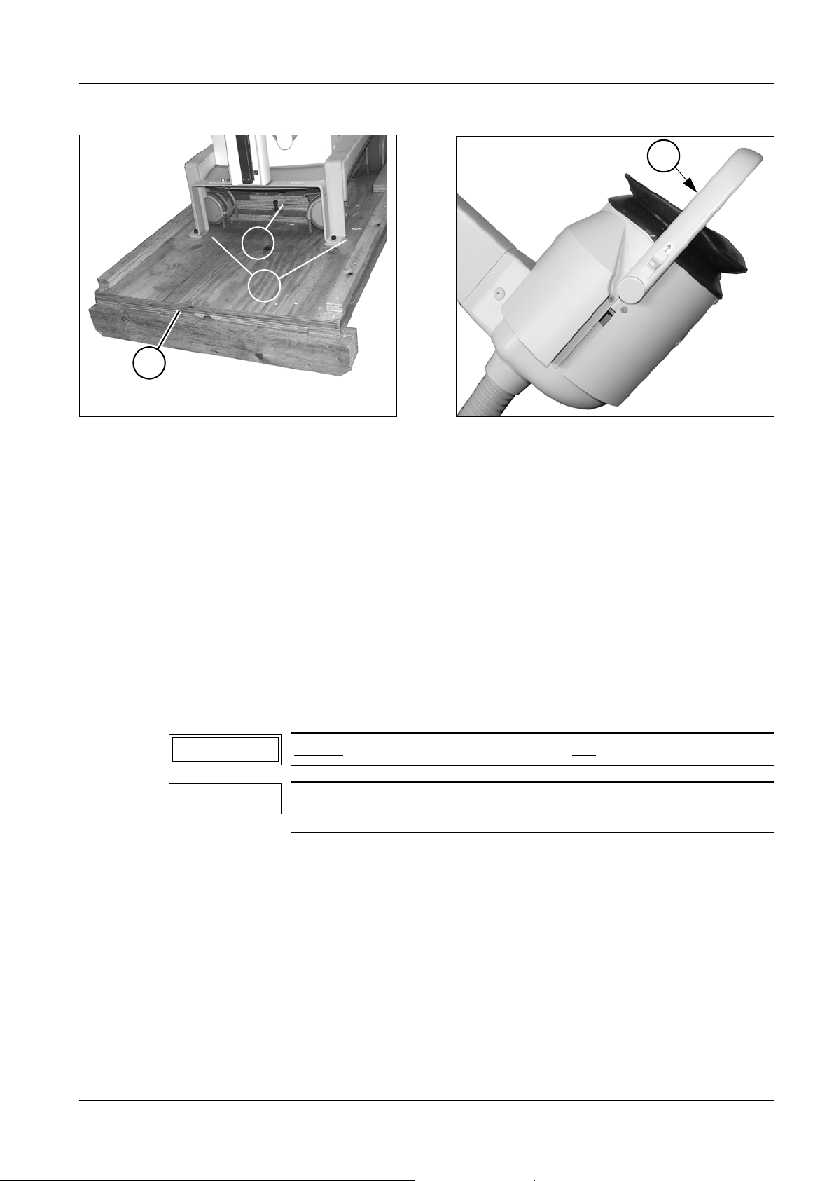
• Remove the packaging above the unit.
• Loosen the transport safety screw (1/Fig. 1) for securing the unit and the ramp (2/Fig. 1).
• Unscrew all transport safety hooks (3/Fig. 1).
pull on the latch (4/Fig. 2). It is not a handle!
Siemens AG SPL1-130.814.03 Page 1 of 4 MODULARIS Uro Plus
Medical Solutions Rev. 04 07.05 CS PS 24
Page 12
2 - 2 Installation
5
Fig. 3
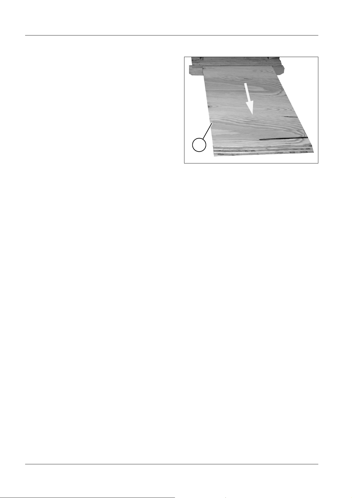
• Pull the ramp out of the transport pallet (5/Fig. 3) from back to front and adjust it to fit
correctly.
• Move the unit off the transport pallet and down the ramp.
• Adapt the power cord to the country-specific requirements, if required. If necessary,
materials will have to be purchased locally. Use a hospital grade plug for the USA and for
Canada.
• Secure the operating panel bracket with the screws.
• Connect the operating panel.
SONOLINE 2
The SONOLINE does not require any special installation instructions.
All you need to do is unpack the unit following the "Unpacking procedure" attached to the
outside and attach the accessories including the monitor.
MUT MODULARIS 2
This system will be started up by the corresponding supplier.
MODULARIS Uro Plus SPL1-130.814.03 Page 2 of 4 Siemens AG
Rev. 04 07.05 CS PS 24 Medical Solutions
Page 13
Installation 2 - 3
Fig. 4 Fig. 5
Fig. 6 Fig. 7
6
8
7
Siemens AG SPL1-130.814.03 Page 3 of 4 MODULARIS Uro Plus
Medical Solutions Rev. 04 07.05 CS PS 24
Page 14

2 - 4 Installation
ECG triggering option 2
Mounting the docking station 2
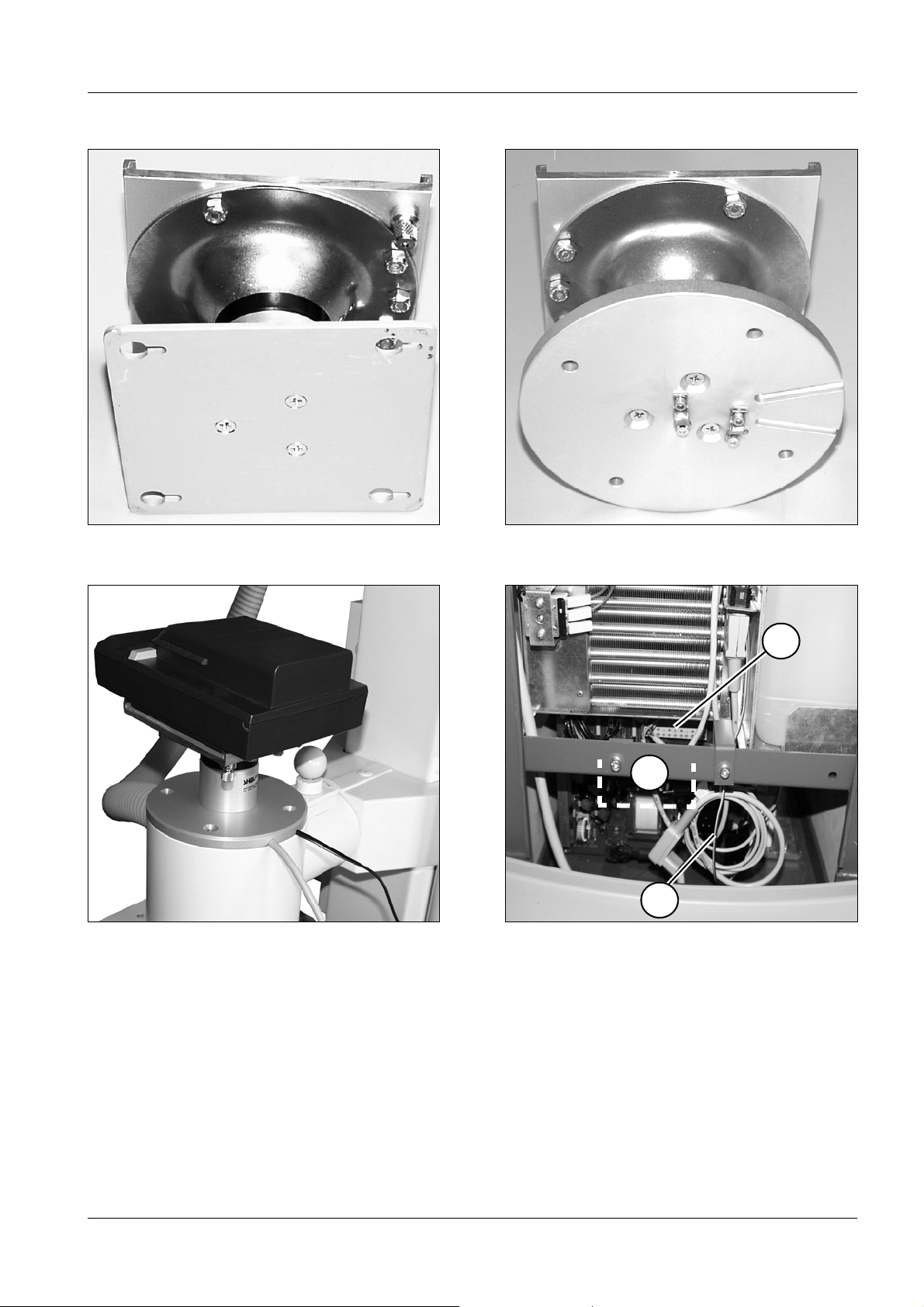
• Unscrew the rectangular plate (Fig. 4) from the ECG-Monitor docking station. It is no
longer required.
• Screw the docking station bracket from the conversion kit onto the round plate so that the
longitudinal grooves are visible from below (Fig. 5).
• Remove the round cap from the column of the system trolley. It is no longer required.
• Remove the cover from the system trolley.
• Loosen the wires at the bracket (7/Fig. 7).
• Connect the cooling unit plug (power cord) to the connecting block (6/Fig. 7).
• Push the trigger cable from the D3.X70 board (beside the service switch) starting with
the jack plug, from beneath, through the column and lead it out, parallel to the wires, with
the network.
• Insert the cold unit plug into the ECG-Monitor power unit.
• Fix the ECG-Monitor power unit in the system trolley onto the bracket (8/Fig. 7) with the
cable tie.
• Push the 24 V cable of the power unit through the column from below and route it as for
the trigger cable.
• Fix both cables, using a cable clamp for each from the conversion kit, onto the mounting
plate so that a length of around 35 cm is available outside the column.
• Screw the plate firmly onto the column so that the cables emerge from the grooved tube
opposite each other, as shown in Fig. 6.
• Connect the Service PC.
• Select the ECG function according to the service instructions.
MODULARIS Uro Plus SPL1-130.814.03 Page 4 of 4 Siemens AG
Rev. 04 07.05 CS PS 24 Medical Solutions
Page 15
Start-up 3
3 - 1
1
Fig. 1 Fig. 2
S3
S4
S2S1
Display
S5
S6
Fig. 3
p
Fill line
3
4
Valve Y8
5
1
2
LITHOSTAR MODULARIS 3
Checking the line voltage 3
• Measure the line voltage at the receptacle.
• Compare the line voltage measured with the value in the test certificate. The voltage can
be converted; the jumper is located on the transformer in the LITHOSTAR MODULARIS.
Siemens AG SPL1-130.814.03 Page 1 of 14 MODULARIS Uro Plus
Medical Solutions Rev. 04 07.05 CS PS 24
Page 16
3 - 2 Start-up
1
2
Fig. 4
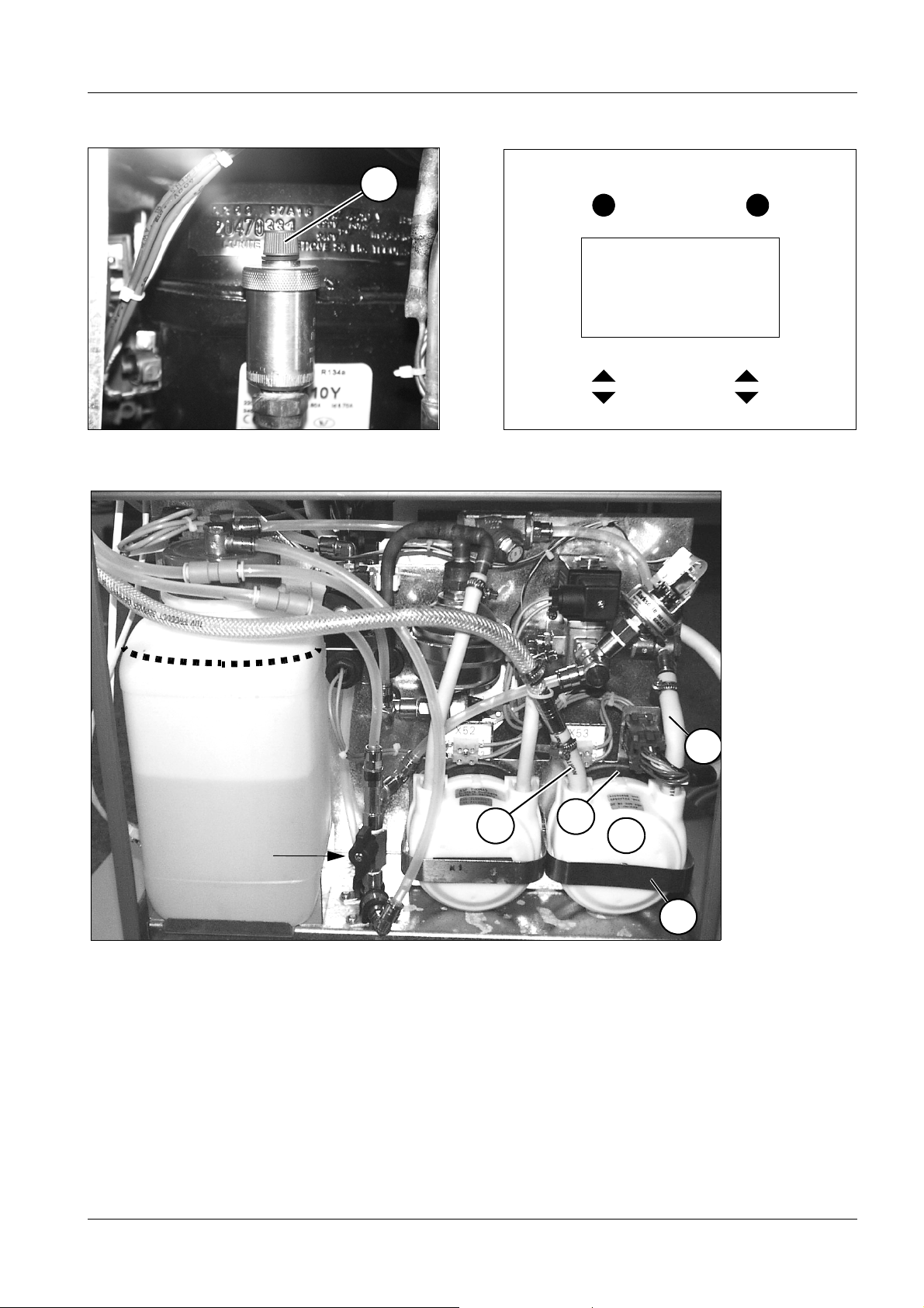
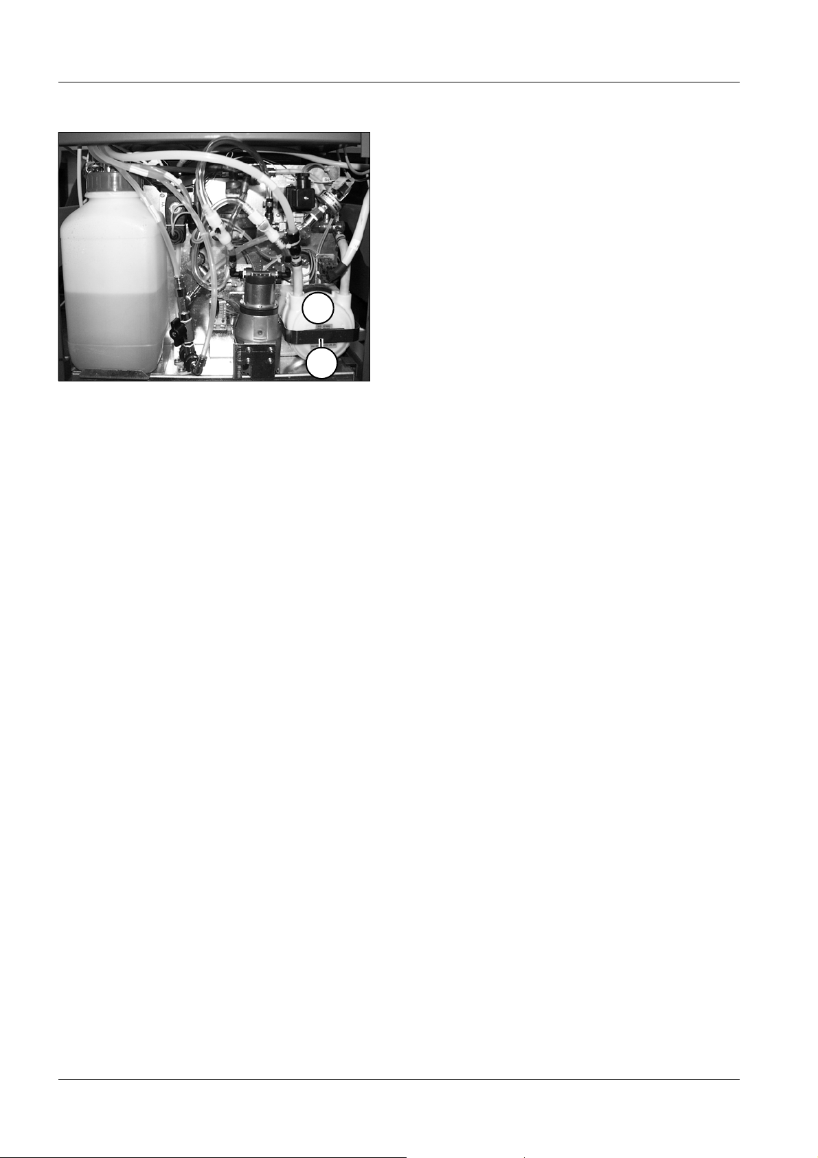
Install coupling pump 3
• The coupling pump is located under the water reserve tank in front of the power supply
board.
• Place the hose pump head on the drive shaft (1/Fig. 3/4).
• Press the black latching mechanism (5/Fig. 3) up or down.
• Install the safety stirrup (2/Fig. 3/4).
• Connect the hoses (3/4/Fig. 3).
Filling the cooling circuit 3
• Remove the system covers.
• Remove the water reserve tank.
• Fill it with distilled water up to the fill line (Fig. 3).
• Reinstall the water reserve tank.
• Switch the system on.
• Move the support arm into the horizontal position.
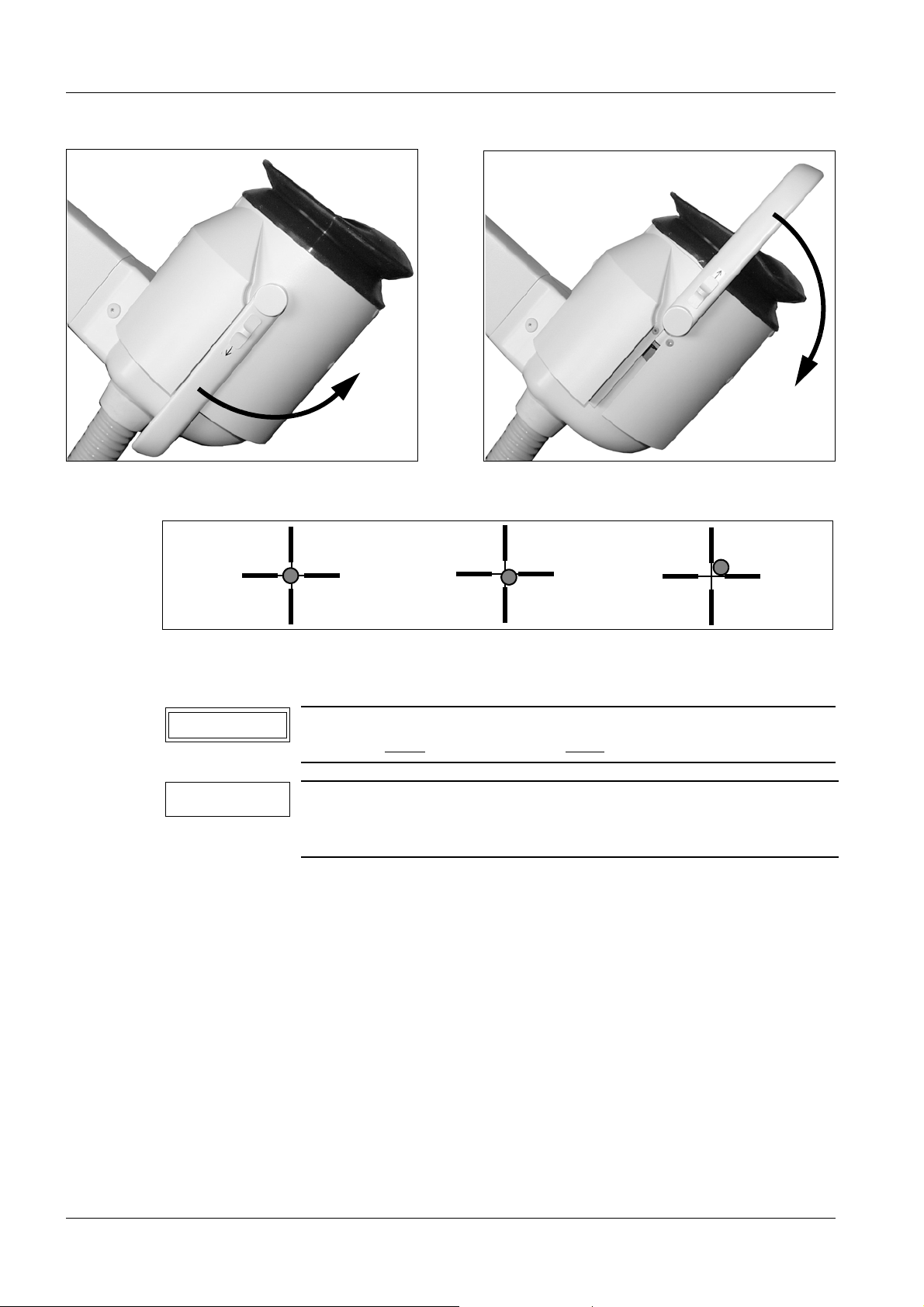
• Turn the ventilation valve (cap) in the cooling unit two revolutions (1/Fig. 1) to open it.
(The valve must always remain open).
• Adjust service switch S2 on board D3 to position 2 (Service on).
• Open valve Y8 (Fig. 3); i.e. turn the lever on Y8 from the horizontal position = closed to
the vertical position = open.
• Select "Service" and then "cooling unit" on the control panel.
• Activate the "fill" switch (S5/Fig. 2) on the operating panel until the water running out of
the return (Fig. 3) into the water reserve tank is free of air bubbles.
(Hose pump M1 will run for as long as this takes, V188 on board D3 lights.)
• Close valve Y8 (Fig. 3); i.e. turn the lever on Y8 from the vertical position = open
to the horizontal position = closed.
MODULARIS Uro Plus SPL1-130.814.03 Page 2 of 14 Siemens AG
Rev. 04 07.05 CS PS 24 Medical Solutions
Page 17

Start-up 3 - 3
Filling the coupling circuit 3
• Select "service" and then "coupling circuit" on the operating panel.
• Activate the "fill" switch (S5/Fig. 2) on the operating panel until the coupling bellow
expands.
• Adjust service switch S2 on board D3 to position 1 (service off).
• Select "rinse" on the operating panel and activate the cycle. This will automatically end
the filling process.
- If you still see air bubbles in the coupling bellow, start the fill cycle again.
• Adjust service switch S2 on board D3 to position 2 (service on).
• First select "service" and then "coupling circuit" on the operating panel.
• Activate the "empty" button (S6/Fig. 2) on the operating panel until the coupling bellow is
located next to the lens.
• Switch the system off.
• Fill the water reserve tank up to the fill line (Fig. 3) with distilled water.
• Adjust service switch S2 on board D3 to position 1 (service off).
• Switch the system on. The "rinse" cycle will be automatically activated and the coupling
bellow will fill.
• Switch the system off.
• Remove the shock head covers and test all sealed transitions for tightness.
Visual inspection of the inlets and outlets, pressure and temperature sensor, coupling
bellows.
• Reattach the system covers.
Siemens AG SPL1-130.814.03 Page 3 of 14 MODULARIS Uro Plus
Medical Solutions Rev. 04 07.05 CS PS 24
Page 18
3 - 4 Start-up
Fig. 5 Fig. 6
requires
correction
Fig. 7
ok
acceptable
Checking the isocenter with X-ray 3
NOTICE
NOTE
If the LITHOSTAR MODULARIS is adjusted for "LithoShare", the
isocenter must
The limit switch for vertical lift on the SIREMOBIL Iso-C may not
switch off if the floor is not level. If this is the case, make use of
the additional steering castors.
be checked with each SIREMOBIL Iso-C.
• Before the isocenter is checked or adjusted, the following settings are required on the
SIREMOBIL Iso-C:
1. Set camera rotation to 0°.
2. Deselect vertical image flip (LED is off).
3. Deselect horizontal image flip (LED is off).
• Couple the LITHOSTAR MODULARIS to the SIREMOBIL Iso-C.
- Connect the cables between the LITHOSTAR MODULARIS and SIREMOBIL Iso-C or
Uro MODULARIS (refer to the Operating Instructions).
• Ensure that the lifting column of the SIREMOBIL cannot move.
If the lifting column can still be moved, proceed according to the service instructions for
LITHOSTAR MODULARIS.
• Flip up the isocenter phantom on the shock wave head (Fig. 5).
MODULARIS Uro Plus SPL1-130.814.03 Page 4 of 14 Siemens AG
Rev. 04 07.05 CS PS 24 Medical Solutions
Page 19
Start-up 3 - 5
1
Fig. 8
• Switch FL on and check the isocenter at 0°, +20° and -20°.
For the admissible position of the ball, see Fig. 7. The ball position at +20° and -20° does
not have to be identical, but does have to be within tolerances.
- If the centering needs to be readjusted, correct in accordance with the
LITHOSTAR MODULARIS Service Instructions, "Isocenter with X-ray" chapter.
• Flip the isocenter phantom back on the shock wave head (Fig. 6).
Shock wave release 3
• Pump water into the coupling bellows.
• Spread some contact gel on the coupling bellows to protect the coupling bellows
(by placing the contact gel on the coupling bellows, it is not damaged as much when a
shock wave is triggered without a patient).
• Increase the shock wave energy in steps from the lowest energy level to the highest
energy level and release additional shock waves at every energy level.
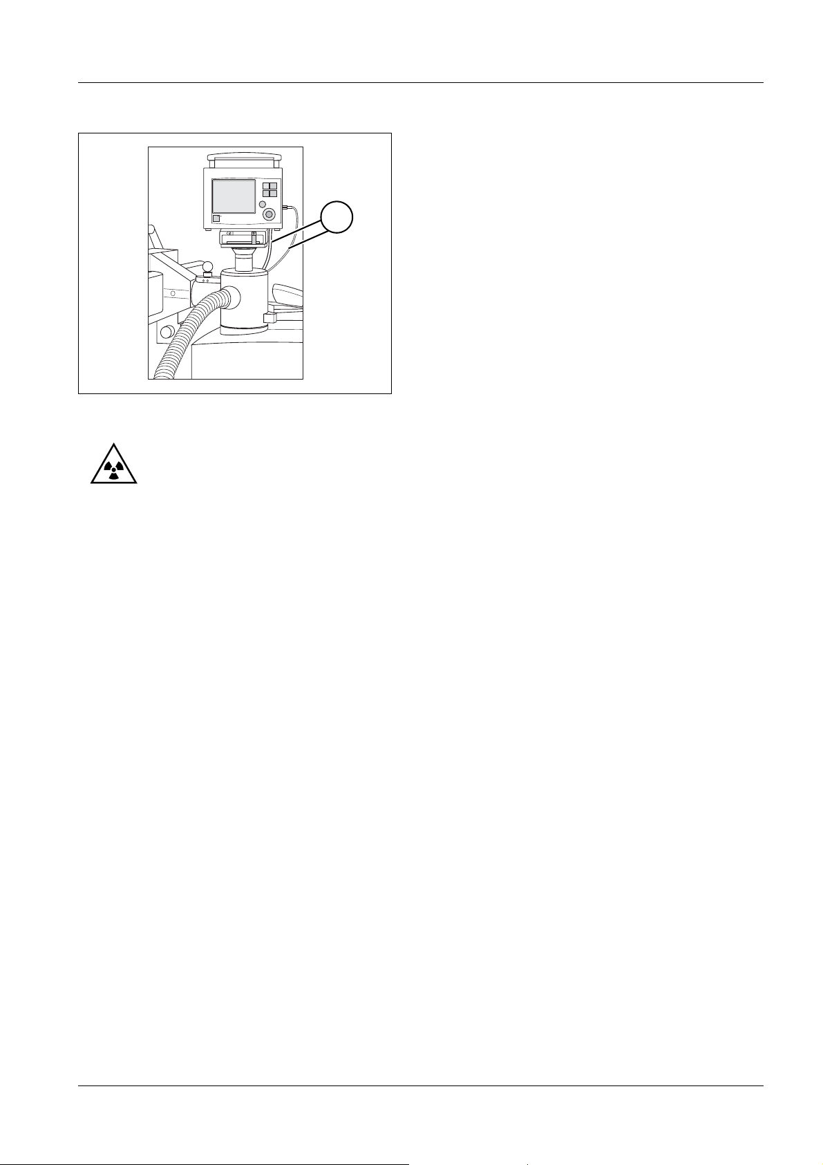
Shock wave release with ECG (optional) 3
• Mount the ECG-Monitor as described in the Operating Instructions to the docking station
(Fig. 8).
• Connect both the cables (1/Fig. 8) to the ECG-Monitor.
• Connect the ECG electrodes to a test subject or connect the ECG simulator to the
ECG-Monitor unit.
• Select ECG triggering on the LITHOSTAR MODULARIS operating panel.
• Spread some coupling gel on the coupling bellow to protect it.
• Increase the shock wave energy in steps from the lowest energy level to the highest
energy level and release additional shock waves at every energy level.
Siemens AG SPL1-130.814.03 Page 5 of 14 MODULARIS Uro Plus
Medical Solutions Rev. 04 07.05 CS PS 24
Page 20
3 - 6 Start-up
Pressure measurement 3
A pressure measurement must be performed after commissioning. The following document is necessary for pressure measurement:
Shock Wave Pressure and Pos. Control: SPL2-120.074.01
ARCADIS Orbic / SIREMOBIL Iso-C and monitor trolley 3
The following documents are required to start-up the SIREMOBIL and monitor trolley:
ARCADIS Orbic SPR2-320.815.02
SIREMOBIL Iso-C: SPR2-230.034.01
MODULARIS Uro 3
The following documents are required to start-up the MODULARIS Uro:
MODULARIS Uro: SPL1-130.033.02
NOTICE
The table is only capable of motorized movement when it is in the
working position, i.e. when the foot pedal is down (refer also to
the MODULARIS Uro Operating Instructions).
• Start-up the table according to the instructions SPL1-130.033.02.. .
• Connect the cables between the LITHOSTAR MODULARIS and the MODULARIS.
• Move the table into Litho mode and check the table movements with the
LITHOSTAR MODULARIS remote control.
The following motorized movements are possible from the LITHOSTAR MODULARIS
control panel:
C-Arm MODULARIS Uro
C-Arm 0° Longitudinal and transverse
C-Arm 20° Lift and transverse
Table movement in the Litho mode (green LED on the table control panel goes on)
e.g. key for longitudinal movement pressed.
Table movement approx. 2 - 3 mm - stops for approx. 2 - 3 seconds - and then
moves on without pausing.
MODULARIS Uro Plus SPL1-130.814.03 Page 6 of 14 Siemens AG
Rev. 04 07.05 CS PS 24 Medical Solutions
Page 21
Start-up 3 - 7
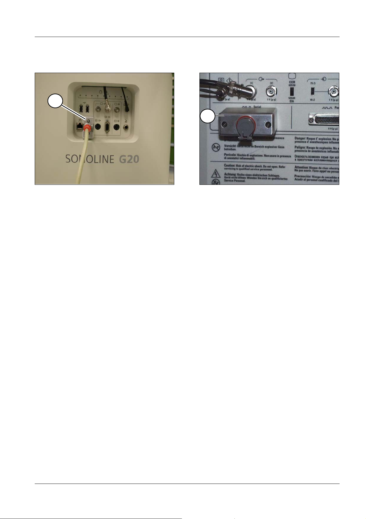
Ultrasound localization (if present)
1
1
Fig. 9 Fig. 10
SONOLINE G20 3
• Screw the plug adapter (1/Fig. 9) onto the serial interface.
• Install the software version V1.0.302 - or higher - in the SONOLINE G20 (see
SONOLINE G20 operating instructions, Chapter 4).
• Enable the ultrasound localization (Chapter 3 of this document "Selection of the
MODULARIS cross.....).
SONOLINE Adara 3
• Screw the plug adapter (1/Fig. 10) onto the serial interface.
• Install the software version 2.0.0 in the SONOLINE Adara (see SONOLINE Adara
operating instructions, section 7-19).
- Only for an existing SONOLINE Adara:
Before the new software V.2.0.0is installed, back up the "defaults" and "quick sets"
(see SONOLINE Adara operating instructions, section 7-15...).
After the software is installed, load the saved presets back in the ultrasound unit (see
SONOLINE Adara operating instructions, section 7-17).
• Enable the ultrasound localization (Chapter 3 of this document "Selection of the
MODULARIS cross.....).
Siemens AG SPL1-130.814.03 Page 7 of 14 MODULARIS Uro Plus
Medical Solutions Rev. 04 07.05 CS PS 24
Page 22

3 - 8 Start-up
1
Fig. 11
SONOLINE Prima 3
• Screw on the plug adapter (1/Fig. 11).
• Install the software version 2.8.0 in the SONOLINE Prima (see SONOLINE Prima
operating instructions, section 8-22).
- Only for an existing SONOLINE Prima:
Before the new software V.2.0.0is installed, back up the "user presets" and "quick sets"
(see SONOLINE Prima operating instructions, section 8-16...).
After the software is installed, load the saved presets back in the ultrasound unit (see
SONOLINE Prima operating instructions).
• Enable the ultrasound localization (Chapter 3 of this document "Selection of the
MODULARIS cross.....).
MODULARIS Uro Plus SPL1-130.814.03 Page 8 of 14 Siemens AG
Rev. 04 07.05 CS PS 24 Medical Solutions
Page 23

Start-up 3 - 9
Probes 3
6
6
4
8
7
5
Fig. 12 Fig. 13
Sector probe 3
• Unscrew all grub screws so far that they do not obstruct the introduction of the probe.
• Push the sleeve as far as possible on the sector probe (1/Fig. 13). Pay attention to
correct position, the marks (3/Fig. 13) and (4/Fig. 13) must be in a line.
• Tighten the 6 screws (3 not visible) (8/Fig. 13).
• Check the ultrasound isocenter (see Chapter 6 of this document).
Array probe 3
• Unscrew all grub screws so far that they do not obstruct the introduction of the probe.
7
2
7
7
3
5
1
2
• Push the sleeve as far as possible on the array probe (2/Fig. 12/13).
Pay attention to correct position, the narrow side with the orange dot (5/Fig. 12/13) must
be in a line(6/Fig. 12/13).
• Tighten the 8 grub screws (7/Fig. 12/13) (4 not visible).
• Check the ultrasound isocenter (see Chapter 6 of this document).
Siemens AG SPL1-130.814.03 Page 9 of 14 MODULARIS Uro Plus
Medical Solutions Rev. 04 07.05 CS PS 24
Page 24

3 - 10 Start-up
Selection of the MODULARIS cross on the SONOLINE G20 3
Ultrasound localization 3
Fig. 14
• In ultrasound localization a holder in which an ultrasound probe can be fastened is fitted
to the shock wave head.
Only the following probes can be used:
C5-2 Convex Array 3.5 MHz
• Press the “F6” key.
• Select the MUP with the trackball.
• Press the key.
• Enter the password.
• With the trackball select "Litho mode without X-ray".
• With the trackball select Save.
• Press the key.
• Deselect the screen saver on the SONOLINE G20 (refer to the SONOLINE G20
operating instructions).
• A cross ( Fig. 14) is displayed when a probe is selected.
MODULARIS Uro Plus SPL1-130.814.03 Page 10 of 14 Siemens AG
Rev. 04 07.05 CS PS 24 Medical Solutions
Page 25

Start-up 3 - 11
Selection of the MODULARIS cross on the SONOLINE Adara 3
Ultrasound localization 3
Fig. 15
• In ultrasound localization a holder in which an ultrasound probe can be fastened is fitted
to the shock wave head.
Only the following probes can be used:
3.5C40S convex array 3.5 MHz
3.5/5.0 SI sector probe
• Press the “F4” key.
• Press the "5" key.
• Select the MUP with the trackball.
• Press the key.
• Enter the password.
• Select "Litho mode without X-ray" with the trackball.
• Press the key.
• Select "Litho mode without X-ray" with the trackball.
• Press the key.
• Press the key two times.
• Deselect the screen saver on the SONOLINE Adara (refer to the SONOLINE Adara
operating instructions).
• A cross (Fig. 15) is displayed when a probe is selected.
Siemens AG SPL1-130.814.03 Page 11 of 14 MODULARIS Uro Plus
Medical Solutions Rev. 04 07.05 CS PS 24
Page 26

3 - 12 Start-up
Selection of the MODULARIS cross on the SONOLINE Prima
Ultrasound localization 3
Fig. 16
• In ultrasound localization a holder in which an ultrasound probe can be fastened is fitted
to the shock wave head.
Only the following probes can be used:
3.5C40S convex array 3.5 MHz
3.5/5.0 SI sector probe
• Press the “F4” key.
• Press the "5" key.
• Select the MUP with the trackball.
• Press the key.
• Enter the password.
• Select "Litho Mode no X-ray" with the trackball.
• Press the key.
• Activate "Litho Mode no X-ray" with the trackball.
• Press the key.
• Press the key two times.
• Deselect the screen saver on the SONOLINE Adara (refer to the SONOLINE Adara
operating instructions).
• When a or probe is selected, the following cross (Fig. 16) is displayed.
MODULARIS Uro Plus SPL1-130.814.03 Page 12 of 14 Siemens AG
Rev. 04 07.05 CS PS 24 Medical Solutions
Page 27

Start-up 3 - 13
1
SIEMENS
Fig. 17
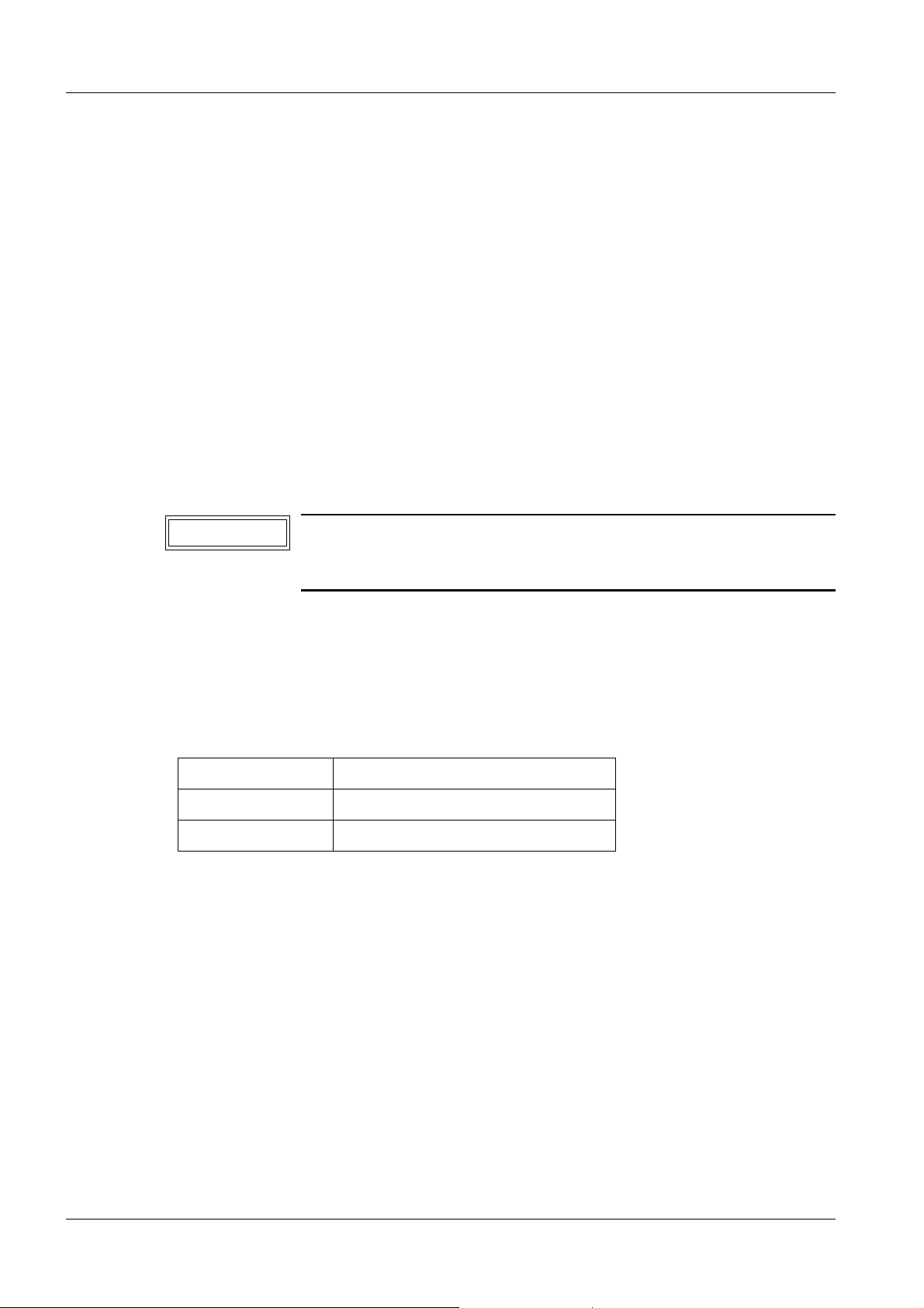
Label for ultrasound unit 3
• Affix the supplied "LITHOSTAR MODULARIS" label to the monitor of the ultrasound unit
(1/Fig. 17) (this label serves for identifying which ultrasound unit operates together with
the LITHOSTAR MODULARIS).
MUT MODULARIS 3
The endoscopy trolley is started up by the manufacturer.
Concluding work 3
Refer to the "Concluding work" chapter.
Siemens AG SPL1-130.814.03 Page 13 of 14 MODULARIS Uro Plus
Medical Solutions Rev. 04 07.05 CS PS 24
Page 28

3 - 14 Start-up
This page intentionally left blank.
MODULARIS Uro Plus SPL1-130.814.03 Page 14 of 14 Siemens AG
Rev. 04 07.05 CS PS 24 Medical Solutions
Page 29

LITHOSTAR MODULARIS retrofit 4
Installing the LITHOSTAR Modularis adaption in ARCADIS Orbic 4
• The installation of the LITHOSTAR Modularis adaption in the ARCADIS Orbic must be
performed according to the instructions SPR2-320.814.04....
Installing the interface wiring in the SIREMOBIL Iso-C 4
• Move the lifting column of the SIREMOBIL Iso-C into the top position.
• Remove the rear panel of the SIREMOBIL Iso-C basic unit.
• Screw on the drilling template as shown in Fig. 1.
4 - 1
Fig. 1 Fig. 2
• To prevent drill shavings from melting into the surface, place a cloth or thin cardboard
over the cover (Fig. 1).
• Inside, also place a cloth or thin cardboard underneath the intended holes.
• With the 3.5 mm drill supplied, drill 3 holes using the holes of the template as a reference.
• Remove the drilling template.
• Using the step drill supplied, open the center hole to 28 mm.
• To do this, drill open the hole until the step drill penetrates the plate down to the mark
shown in Fig. 2 (approx. 0.5 mm from the largest drill diameter of 30 mm).
• Drill slowly! (approx. 300 to 500 rpm).
Siemens AG SPL1-130.814.03 Page 1 of 12 MODULARIS Uro Plus
Medical Solutions Rev. 04 07.05 CS PS 24
Page 30

4 - 2 LITHOSTAR MODULARIS retrofit
1
1
Fig. 3 Fig. 4
• When drilling, ensure that the drill is placed vertically against the plate.
• Due to the step length of the drill, a small 26 mm diameter bridge remains on the inner
edge of the hole. Remove this bridge with a half-round file. The diameter drilled shall be
28 mm across the entire plate thickness. Use the file to remove the burr as well.
• Also deburr the two 3.5 mm holes. This can be done with a drill having a diameter of
approx. 8 mm to 10 mm. Place the drill manually against the 3.5 mm holes from the
inside and break the burr.
• Remove all drill shavings outside and inside with a vacuum cleaner.
• Varnish the 28 mm hole with a varnish applicator and allow it to dry.
• Position the connector with holding plate from the inside.
• The connector is positioned centrally to the 28 mm hole, the lid opens downward.
• Fasten the connector with holding plate using the screws and lock washers supplied
(1/Fig. 3).
• Route the cables along the guide plate (1/Fig. 5).
MODULARIS Uro Plus SPL1-130.814.03 Page 2 of 12 Siemens AG
Rev. 04 07.05 CS PS 24 Medical Solutions
Page 31

LITHOSTAR MODULARIS retrofit 4 - 3
2
1
1
Fig. 5 Fig. 6
Without SIREMOBIL Iso-C 3D option:
• Run the cable end with the designation X11 to D30 (2/Fig. 5) and connect it to the
connector D30.X11 and lock it. Refer to the wiring diagram for the position of the
connector D30.X11.
With SIREMOBIL Iso-C 3D option:
• Disconnect at both ends and remove the existing ribbon cable from D30.X11 to
D200.X211. The ribbon cable is no longer required. Refer to the wiring diagrams for the
position of the connectors D30.X11 and D200.X211.
• Fasten the top hat rail (1/Fig. 4) at the place shown in (Fig. 4). For this purpose loosen
the existing screws and fasten the top hat rail with these.
• Run the cable end with the designation X11 to D30 (2/Fig. 5) and connect it to the
connector D30.X11 and lock it.
• Fasten the single lead to the terminal M10.L+ (1/Fig. 6).
Without SIREMOBIL Iso-C 3D option:
• The cable end with the designation X211 is not used. Fasten the cable end securely with
cable ties.
With SIREMOBIL Iso-C 3D option:
• Run the cable end with the designation X211 to the board D200 and connect it to the
connector D200.X211.
Siemens AG SPL1-130.814.03 Page 3 of 12 MODULARIS Uro Plus
Medical Solutions Rev. 04 07.05 CS PS 24
Page 32

4 - 4 LITHOSTAR MODULARIS retrofit
• Using the cable ties supplied, fasten the cables along the existing cables. Ensure that the
cables cannot be pinched when the covers are closed and the lifting column is moved.
NOTE
The "Appendix" contains the wiring diagram excerpt for the cable
in Fig. 3. Please take the wiring diagram excerpt out of this document and file it with the wiring diagram of the SIREMOBIL Iso-C
(SIREMOBIL Iso-C system binder).
MODULARIS Uro Plus SPL1-130.814.03 Page 4 of 12 Siemens AG
Rev. 04 07.05 CS PS 24 Medical Solutions
Page 33

LITHOSTAR MODULARIS retrofit 4 - 5
Fig. 7
2
2
1
3
1
2
3
1
Mounting the docking plate on the ARCADIS Orbic / SIREMOBIL Iso-C
LITHOSTAR MODULARIS with support arm beginning with 0051/ or with "LithoShare" 4
• Remove the cap plugs on the horizontal carriage.
• Disassemble the two-part docking plate by removing the eight screws (1/Fig. 7).
• Attach the docking plate on the horizontal carriage by tightening the screws to a torque of
18 Nm (Fig. 9). The docking plate must be down on the threads of the mounting screws.
• Adjusting the clamping force:
The adjustment steps must be performed evenly and parallel on both hooks.
- Loosen both clamping screws (2/Fig. 7) so that it is possible to move the hooks,
however, the hooks may not slide down under their own weight.
- Turn the hooks (3/Fig.7) all the way up.
- Hook the part of the docking plate that was removed onto the LITHOSTAR
MODULARIS and close the latching lever.
- Using the adjustment screw (3/Fig.7), turn down the hook with a torque of
2.3 + 0.3 Nm.
- Remove the plate on the LITHOSTAR MODULARIS.
- Tighten the screws (2/Fig. 7) with a torque of 10 Nm.
- Place the cover caps over the screws (2/Fig. 7).
4
Siemens AG SPL1-130.814.03 Page 5 of 12 MODULARIS Uro Plus
Medical Solutions Rev. 04 07.05 CS PS 24
Page 34

4 - 6 LITHOSTAR MODULARIS retrofit
1
Fig. 8 Fig. 9
• Reinstall the part of the docking plate that was removed on the C-arm.
It must still be possible to move it using the adjustment screws (1/Fig. 8).
When fitting the plate, make sure that the switches in the C-arm do not get damaged.
1
Attaching the alignment marker to the ARCADIS Orbic / SIREMOBIL Iso-C
B
C
4
• Attach the alignment marker in the center of the C-arm foot (B/Fig. 9).
The marker is included with the alignment fixture in the system delivery volume
(C/Fig. 9).
MODULARIS Uro Plus SPL1-130.814.03 Page 6 of 12 Siemens AG
Rev. 04 07.05 CS PS 24 Medical Solutions
Page 35

LITHOSTAR MODULARIS retrofit 4 - 7
10
9
11
Fig. 10 Fig. 11
Attaching the marker on the C-arm 4
• Position the C-arm in the vertical position with the aid of a spirit level (Place the water
level on the I.I.).
• Attach (20/Fig. 15) the arrow marker.
Mounting the coupling 4
Not "LithoShare"
• If not present
- Drill a hole, 5 mm in diameter and 20 mm deep in the shaft of the C-arm
(9/Fig. 10).
- Cut M6 threads in the hole to a minimum depth of 16 mm.
• Place the item shown in (10/Fig. 11) in the center of the shaft and attach it with the screw
(11/Fig. 11) and Loctite 221.
• Remove both parts of the cover from the motor.
• The angulation motor should be easy to remove from the axis of the C-arm;
if not, proceed according to the LITHOSTAR MODULARIS Service Instructions,
SPL1-130.061.01.
With "LithoShare"
• With a C-arm, install the coupling as described under "Not LithoShare".
• With all other Siremobil systems, as described below:
- Prerequisite: Motor is perfectly adjusted.
- Push coupling (10/Fig. 11) on to the motor coupling.
- Couple the motor with the coupling to the SIREMOBIL Iso-C.
- Just hold the coupling and bring the motor back into the parking position (do not
displace the coupling).
- Attach the coupling with the screw (11/Fig. 11) and Loctite 221.
Siemens AG SPL1-130.814.03 Page 7 of 12 MODULARIS Uro Plus
Medical Solutions Rev. 04 07.05 CS PS 24
Page 36

4 - 8 LITHOSTAR MODULARIS retrofit
18
17
13
12
Fig. 12 Fig. 13
14
15
Fig. 14 Fig. 15
Installing the controls in the monitors, item no. 11 02 628 4
• Remove the regulator unit (14/Fig. 12) from the monitor by unlocking both snap-in locks
(12/Fig. 12) and swiveling the unit downward. Disconnect the plug (13/Fig. 12) and
remove the unit.
16
19
20
• Remove the screws and the cover plate (15/Fig. 14).
• Press and remove the cover caps (16/Fig. 13).
• Rotate the potentiometers clockwise to the end stop.
• Install the knobs (17/Fig. 13) on the potentiometers; the markers (single line) on the
knobs must be centered in the panel cutout.
• Snap on the top holder (18/Fig. 13) to secure the knobs.
• Insert the stop pins (19/Fig. 13) into the holes (slot must be vertical).
• Reinstall the covers.
• Install the regulator unit in the monitor.
• If there is a second monitor, perform the installation described above on the second
monitor as well.
MODULARIS Uro Plus SPL1-130.814.03 Page 8 of 12 Siemens AG
Rev. 04 07.05 CS PS 24 Medical Solutions
Page 37

LITHOSTAR MODULARIS retrofit 4 - 9
Fig. 16 Fig. 17
2
2
1
Fig. 18 Fig. 19
1
1
1
Fig. 20 Fig. 21
Siemens AG SPL1-130.814.03 Page 9 of 12 MODULARIS Uro Plus
Medical Solutions Rev. 04 07.05 CS PS 24
Page 38

4 - 10 LITHOSTAR MODULARIS retrofit
Installing the isocenter crosshairs on the C-Arm 4
LITHOSTAR MODULARIS with support arm Ser. No. 0051 or with "LithoShare" 4
• Remove the front screw on the I.I. and replace it with the M4 x 16 screw included in the
shipment (1/Fig. 18).
• Snap the isocenter cross onto the I.I.
• Attach the arrows (Fig. 17) (indicators for the centering stud).
• Attach the Serial No. label included in the shipment on the isocenter cross (1/Fig. 19) and
place it on the back of the I.I. (2/Fig. 18/19).
Unit assignment 4
• Attach the supplied label "LITHOSTAR MODULARIS" to the docking plate (1/Fig. 20)
and to the LITHOSTAR MODULARIS (1/Fig. 21) and add LITHOSTAR MODULARIS
serial number.
Checking the decoupling of the angulation drive 4
• If the error messages E24 and E28 appear when swiveling the C-arm, the cause for
these messages can be that the angulation brake in the SIREMOBIL is set too firmly.
• Setting of the angulation brake in the C-arm (angulation and orbital in 0°). LITHOSTAR
MODULARIS not coupled. Fit the spring balance on the handle near the
X-ray I.I. Release the angulation brake, pull with the spring balance; the C-arm must
move when the spring balance indicates a value from 20N, 30N, the closer to 20N the
better. Adjustable at the location where the angulation motor is coupled. Wrench opening 30 mm. The coupling must be removed for this. See also SPR2-230.061.01...
Chapter 7.
• Move the C-arm to the 0° position.
• Couple the LITHOSTAR MODULARIS to the C-arm.
- Connect the cables between the LITHOSTAR MODULARIS and SIREMOBIL Iso-C
(refer to the Operating Instructions).
• The angulation motor should be easy to remove from the axis of the C-arm;
if not, proceed according to the LITHOSTAR MODULARIS Service Instructions,
SPL1-130.061.01.
Isocenter 4
• Proceed according to the LITHOSTAR MODULARIS Service Instructions
SPL1-130.061.01 ("Isocenter with X-ray" chapter).
Water system 4
• Proceed according to chapter 3 of these instructions, LITHOSTAR MODULARIS
SPL1-130.061.01 section.
MODULARIS Uro Plus SPL1-130.814.03 Page 10 of 12 Siemens AG
Rev. 04 07.05 CS PS 24 Medical Solutions
Page 39

LITHOSTAR MODULARIS retrofit 4 - 11
MEMOSKOP programming for lithotripsy operation 4
• Proceed according to the LITHOSTAR MODULARIS Service Instructions
SPL1-130.061.01.
Siemens AG SPL1-130.814.03 Page 11 of 12 MODULARIS Uro Plus
Medical Solutions Rev. 04 07.05 CS PS 24
Page 40

4 - 12 LITHOSTAR MODULARIS retrofit
MODULARIS Uro Plus SPL1-130.814.03 Page 12 of 12 Siemens AG
Rev. 04 07.05 CS PS 24 Medical Solutions
Page 41

Ultrasound localization retrofit 5
5 - 1
b
1
Fig. 1 Fig. 2
2
2
1
b
a
3
1
c
Fig. 3
NOTE
For systems with a serial no. including 01017:
The modification SP005/99R (software and new cable) must have
been performed.
For systems with a serial no. including 01024:
An isocenter phantom with a serial no. must be fitted.
• Remove the cover from the trolley.
• Remove each of the 4 covers from the installation openings for parts (2 and 3/Fig. 2).
• Check that the lower installation openings for part (3/Fig. 2) are accessible.
If not, mark them on the cover.
• Remove the shock wave head cover and take out the cable (1/Fig. 1).
• Check that connector X28 is connected to board D3; if it is not, then connect it. Pull the
entire excess length of this cable to the shock wave head if not yet done.
• If necessary, deepen the installation opening on the cover for part (3/Fig. 2) by filing.
Siemens AG SPL1-130.814.03 Page 1 of 8 MODULARIS Uro Plus
Medical Solutions Rev. 04 07.05 CS PS 24
Page 42

5 - 2 Ultrasound localization retrofit
1
1
Fig. 4 Fig. 5
• Only for systems with a serial no. including 01024:
- Mark the two openings (1/Fig. 3) on the retaining section of the isocenter phantom.
- Loosen the 4 safety screws (2/Fig. 3) on the isocenter phantom.
- Remove the isocenter phantom.
- Drill holes in the marked positions:
pilot-drill to 4 mm
drill to 8 mm and debur
the depth of the hole must be 10 - 15 mm.
- Replace the isocenter phantom and screw down.
• Replace the cover and route the cable (1/Fig. 2) out of the cover.
• Screw parts (2 and 3/Fig. 2) together with the loose spacer.
Fastening:
- a/Fig. 2: long sleeve, screw: M5 x 40 mm
- b/Fig. 2: short sleeve, screw: M5 x 21 mm
- c/Fig. 2: short sleeve, screw: M5 x 24 mm.
• Remove the cover from the control (1/Fig. 4).
• The retaining pins are already mounted on the board (AS 03).
- Attach additional board MUP D3 from the conversion kit in position (1/Fig. 5) and screw
down.
• Before mounting the retaining pins on the board.
- Remove all cables.
- Remove the control.
- Remove the board from the mounting.
- Mount the retaining pins.
- Screw the board to the mounting again.
- Attach additional board MUP D3 from the conversion kit in position (1/Fig. 5) and screw
down.
- Replace the control.
- Reconnect all cables.
• Reattach the cover on the control (1/Fig. 4).
MODULARIS Uro Plus SPL1-130.814.03 Page 2 of 8 Siemens AG
Rev. 04 07.05 CS PS 24 Medical Solutions
Page 43

Ultrasound localization retrofit 5 - 3
2
45
1
Fig. 6 Fig. 7
Fig. 8
1
• Unscrew the mounting (1/Fig. 7) (to facilitate installation of the cables at a later point,
mark the length and position).
• If three connector mountings (Fig. 6) are not available, then drill a 2.5 mm hole
(see Fig. 6). Mount the connector mounting as for those opposite.
• Connect the cable from the conversion kit to board D3.X29 in the LITHOSTAR
MODULARIS.
• Screw down the mounting (1/Fig. 7) again with the three old cables and the new cable.
• At the back of the SONOLINE Prima mount the adapter from the conversion kit to the
RS 2332C connection (1/Fig. 15, 16, 17).
Cable mounting on the carrier arm 5
• Instead of the covering screw, use the screw supplied to screw down the mounting
(1/Fig. 8).
Siemens AG SPL1-130.814.03 Page 3 of 8 MODULARIS Uro Plus
Medical Solutions Rev. 04 07.05 CS PS 24
Page 44

5 - 4 Ultrasound localization retrofit
1
1
2
Fig. 9 Fig. 10
Cable holder on the cable 5
• If the holder (1/Fig. 9) is not yet located on the cable for the ultrasound mounting, then
proceed as follows:
- Unscrew connectors, hold part (1/Fig. 10) firmly and rotate part (2/Fig. 10).
- Push holder (1/Fig. 9) onto part 2 (the depression must be pointing towards part 2).
- Screw connectors together again.
Ultrasound probes 5
• Prepare the sector probe/ array probe according to Chapters 3 - 9 of this document.
MODULARIS Uro Plus SPL1-130.814.03 Page 4 of 8 Siemens AG
Rev. 04 07.05 CS PS 24 Medical Solutions
Page 45

Ultrasound localization retrofit 5 - 5
1
1
Fig. 11 Fig. 12
1
ok
ok
not ok
Fig. 13
2
24 -1 mm
1
Compensating springs for carrier arms 5
Only for systems up to and including Serial No. 01024.
• Put the carrier arm in a vertical position. Remove the cover from the column and the
mounting for the ECG triggering.
• Remove the cover from the high voltage connection on the charging set (it will be easier
to remove the spring mounting).
• Remove the 3 screws (1/Fig. 11) and then remove the spring mounting downwards.
• Replace the compensating springs (2/Fig. 12) with new ones.
- For the mounting (1/Fig. 12) make sure to set the correct distance (see Fig. 12).
• Replace the spring mounting.
• Carry out the following check:
- Position the carrier arm horizontally and in the docking position (central locking pos.).
- Place a spirit level on the carrier arm (1/Fig. 13).
- The bubble may move to the right, but not to the left
• Check the isocenter with X-Ray.
Siemens AG SPL1-130.814.03 Page 5 of 8 MODULARIS Uro Plus
Medical Solutions Rev. 04 07.05 CS PS 24
(Fig. 13).
Page 46

5 - 6 Ultrasound localization retrofit
1
SIEMENS
Fig. 14
Adhesive labels for ultrasound unit 5
• Attach the "LITHOSTAR MODULARIS" label included in the shipment on the monitor of
the ultrasound unit (1/Fig. 14) (this label is used to identify which ultrasound unit is
functioning with the LITHOSTAR MODULARIS).
Adjustment and startup 5
• Switch the system on.
• Set the S2 switch on the D3 board to the Service position.
• Connect the Service PC and establish the connection (see Service Instructions,
Chap. 3).
• Software VA00F or higher must be installed in the LITHOSTAR MODULARIS.
If it is not, install the software from the update kit.
See Service Instructions, SPL1-130.061.01.
• Install the software for the ultrasound unit, according to unit type (Chap. 3-7).
• Enable ultrasound localization (Chapter 3 of this document, "Selecting the MODULARIS
crosshairs.....).
• Check the isocenter with X-ray.
• Check the isocenter as described in Chapter 6 of this document.
MODULARIS Uro Plus SPL1-130.814.03 Page 6 of 8 Siemens AG
Rev. 04 07.05 CS PS 24 Medical Solutions
Page 47

Ultrasound localization retrofit 5 - 7
1
1
Fig. 15 Fig. 16
LithoShare with several ultrasound units 5
Perform for each ultrasound unit.
SONOLINE G20 5
• Screw the plug adapter (1/Fig. 15) onto the serial interface.
• Install the software version V1.0.302 - or higher - in the SONOLINE G20 (see
SONOLINE G20 operating instructions, Chapter 4).
• Enable the ultrasound localization (Chapter 3 of this document "Selection of the
MODULARIS cross.....).
SONOLINE Adara 5
• Screw the plug adapter (1/Fig. 16) onto the serial interface.
• Install the software version 2.0.0 in the SONOLINE Adara (see SONOLINE Adara
operating instructions, section 7-19).
- Only for an existing SONOLINE Adara:
Before the new software V.2.0.0is installed, back up the "defaults" and "quick sets"
(see SONOLINE Adara operating instructions, section 7-15...).
After the software is installed, load the saved presets back in the ultrasound unit (see
SONOLINE Adara operating instructions, section 7-17).
• Enable the ultrasound localization (Chapter 3 of this document "Selection of the
MODULARIS cross.....).
Siemens AG SPL1-130.814.03 Page 7 of 8 MODULARIS Uro Plus
Medical Solutions Rev. 04 07.05 CS PS 24
Page 48

5 - 8 Ultrasound localization retrofit
1
Fig. 17
SONOLINE Prima 5
• Screw on the plug adapter (1/Fig. 17).
• Install the software version 2.8.0 in the SONOLINE Prima (see SONOLINE Prima
operating instructions, section 8-22).
- Only for an existing SONOLINE Prima:
Before the new software V.2.0.0is installed, back up the "user presets" and "quick sets"
(see SONOLINE Prima operating instructions, section 8-16...).
After the software is installed, load the saved presets back in the ultrasound unit (see
SONOLINE Prima operating instructions).
• Enable the ultrasound localization (Chapter 3 of this document "Selection of the
MODULARIS cross.....).
• Prepare the ultrasound probes according to section 3-9 of this document.
• Check the isocenter according to Chapter 6 of this document.
MODULARIS Uro Plus SPL1-130.814.03 Page 8 of 8 Siemens AG
Rev. 04 07.05 CS PS 24 Medical Solutions
Page 49

Isocenter with ultrasound 6
Preparations 6
2
6 - 1
Fig. 1
4
3
6
5
7
1
2
1
2
Fig. 2 Fig. 3
NOTE
Only the probes approved for the corresponding SONOLINE may
be used.
• Fit the holder (1/Fig.1) (see also the operating instructions).
• Insert an ultrasound probe (sector probe (1/Fig. 2) or array probe
(2/Fig. 2/Fig. 3) in the holder (3/Fig. 1). Carefully insert the cable of the probe in the
longitudinal groove (4/Fig. 1).
• Plug in the cable (2/Fig. 1) and connect the probe to the ultrasound unit.
• Make the cable connection (marked orange) between LITHOSTAR MODULARIS and
the ultrasound unit.
Siemens AG SPL1-130.814.03 Page 1 of 16 MODULARIS Uro Plus
Medical Solutions Rev. 04 07.05 CS PS 24
Page 50

6 - 2 Isocenter with ultrasound
Checking the target on the Sonoline G20 6
1
2
Fig. 4 Fig. 5
NOTE
NOTE
The isocenter must be checked with evry type of probe and after
every probe change.
The designations of the keys can vary according to language
version.
Comparison table, see SONOLINE operating instructions.
• Set the value (1/Fig. 4, 5) to 180 with the "Image field/zoom" knob.
• Push the ultrasound probe as far as possible up to the shock wave head.
• Press the "Measurement" key and select the "Set" measuring mark.
• Move to the center of the crosshair with the trackball. A value of 13 mm + 1 mm must
appear in the display (2/Fig. 4).
1
2
• Press the "Measurement" key ("Freeze" is deselected).
• Shift the ultrasound probe as far as possible in the other direction.
• Press the "Measurement" key and select the "Set" measuring mark.
• Move to the center of the crosshair with the trackball. A value of 151 mm + 1 mm must
appear in the display (2/Fig. 5).
• If this is not the case, the adjustment process for the potentiometer in the ultrasound arm
must be repeated or the ultrasound arm must be replaced.
MODULARIS Uro Plus SPL1-130.814.03 Page 2 of 16 Siemens AG
Rev. 04 07.05 CS PS 24 Medical Solutions
Page 51

Isocenter with ultrasound 6 - 3
2
3
2
1
1
Fig. 6 Fig. 7
Check of image tilt 6
NOTE
The isocenter must be checked mit every type of probe and after
every
probe change
• Check that the isocenter phantom (1/Fig. 6) is filled with water, if not remove the screw
(2/Fig. 6) and fill water with a syringe (3/Fig. 6).
No air bubbles may be present. Screw the screw back in.
• Hinge the isocenter phantom up.
• Fill the water bladder with water (approx. 100 - 120 ml, i.e. 5 - 6 syringes @20 ml)
(1/Fig. 7):
- Fill a syringe with distilled water. Remove the air remaining in the syringe.
- Push the syringe needle through one of the valves (2/Fig. 7) and empty the contents of
the syringe into the water bladder. The valve has a self-closing membrane.
- Repeat the filling process until the water bladder if filled with approx. 200 - 120 ml
water.
- After filling there must not be any air bubbles in the water bladder; withdraw air bubbles
with the syringe.
• Apply contact gel to the isocenter phantom.
• Fasten the water bladder (5/Fig. 1) with the holding part (6/Fig. 1) to the isocenter
phantom.
• Apply contact gel to the ultrasound probe.
• With the "Image field/zoom" knob set the value "50" (Fig. 8) - bottom left in the ultrasound
image.
• Push the probe so far forwards (3/Fig. 1) until the isocenter cross is approximately in the
center of the SONOLINE Prima screen.
• Press the menu key and display this.
Siemens AG SPL1-130.814.03 Page 3 of 16 MODULARIS Uro Plus
Medical Solutions Rev. 04 07.05 CS PS 24
Page 52

6 - 4 Isocenter with ultrasound
1
Fig. 8 Fig. 9
• Make the following basic settings on the ultrasound unit:
Value: Setting with: German English French Spanish
5
(Fig. 8)
35 dB (Fig. 8) Set trackball to DR
Set trackball to Edge
(white background)
then press and
set value with
"Select" controller.
(white background)
then press and
set value with
"Select" controller.
FV Edge Côté Contorno
DR Dyn Rng DR Cam Din
• Set all slide controls all the wayto the left.
• The image flip key must not be selected.
• The corresponding ultrasound probe is selected on switching on. If a second ultrasound
probe is present, then select the probe with the key.
• Check that the ultrasound arm is as shown in Fig. 1, if not align it.
The longitudinal groove must be visible (1/Fig. 9).
MODULARIS Uro Plus SPL1-130.814.03 Page 4 of 16 Siemens AG
Rev. 04 07.05 CS PS 24 Medical Solutions
Page 53

Isocenter with ultrasound 6 - 5
1
2
Fig. 10
Distance check: height
• Press the "Measurement" key.
• With the trackball set the cross on center of target cross.
• Press the Measurement key.
• Move the trackball until the cross lies in the center of the isocenter cross (1/Fig. 10).
• Press the "Measurement" key.
• Move the cross "+2" with the trackball on the longitudinal axis of the target line into the
isocenter.
• Press the key.
• Move the cross with the trackball horizontally into the center of the white area on the
isocenter phantom.
• The displayed value for "D2" (2/Fig. 10) must be between 1 and 5 mm. This has validity
only for the default values, see instructions SPL1-130.038.01.. .
• Press the key.
Distance check: side
• Press the key two times (cross "+1" is not required in this measurement).
• Move the cross "+2" with the trackball onto the longitudinal axis of the target line, at the
height of the isocenter.
• Press the key.
• Move the cross with the trackball horizontally into the center of the white area on the
isocenter phantom.
Siemens AG SPL1-130.814.03 Page 5 of 16 MODULARIS Uro Plus
Medical Solutions Rev. 04 07.05 CS PS 24
Page 54

6 - 6 Isocenter with ultrasound
• If the center point of the white area is not in the isocenter (allowed deviation ± 0,5 mm
from the center):
- Note the value of D2 (with sign):
If the ball image is displayed shifted to the left of the isocenter, then the correction
value must receive a negative sign (to the right is positive sign).
- Press the F6 key.
- Select "MUP" with the trackball.
- Press the "Set" key
- Press the "5" key.
- Enter the password.
- Select ok with the trackball.
- Press the "Set" key.
- With the trackball select the value for image tilt and increase it with the "Set" key.
German: Bildneigung Array French: Basculement d’image sondes conv.
English: Image Tilt Array Spanish: Inclinar imagen transductor curvo
- Set half value of D2.
Example: D2 = 1.2 mm
- Press the key.
⇒ enter -06 .
- Check the deviation, if the white area is not in the center of the isocenter, repeat the
process.
• After the setting fasten the holder for the ultrasound probe to the holding point (7/Fig. 1).
With every probe check that the setting in this position is also in order. Make no changes
to the image tilt setting.
• After the check stow the parts in the corresponding transport cases.
MODULARIS Uro Plus SPL1-130.814.03 Page 6 of 16 Siemens AG
Rev. 04 07.05 CS PS 24 Medical Solutions
Page 55

Isocenter with ultrasound 6 - 7
F
D
Fig. 11 Fig. 12
Checking the target on the Sonoline Adara 6
NOTE
• Set the value (D/Fig. 10,11) to 180 using the knob .
• Slide the ultrasound probe all the way forward to the shock wave head.
• Press the key and select the measuring point .
• Use the track ball to move to the center of the crosshairs. In the display (F/Fig. 11), a
value of - see Table - must appear that is relative to the probe.
Probe Changeover with Value for D1
Sector (1/Fig. 2) 15 ± 1 mm with default values,
Array (2/Fig. 2) 13 ± 1 mm
The isocenter must be checked with every probe type and after
every
replacement of a probe.
F
D
see SPL1-130.038.01
• Press the key ("Freeze" is deselected).
• Move the ultrasound probe all the way in the other direction.
• Press the key and select the measuring point .
• Use the track ball to move to the center of the crosshairs. In the display (F/Fig. 12), a
value of - see Table - must appear that is relative to the probe. If this is not the case, the
adjustment procedure must be repeated for the potentiometer in the ultrasound arm or
the ultrasound arm must be replaced.
Probe Changeover with Value for D1
Sector (1/Fig. 2) 153 ± 1 mm with default values,
Array (2/Fig. 2) 151 ± 1 mm
see SPL1-130.038.01
• Press the key ("Freeze" is deselected).
Siemens AG SPL1-130.814.03 Page 7 of 16 MODULARIS Uro Plus
Medical Solutions Rev. 04 07.05 CS PS 24
Page 56

6 - 8 Isocenter with ultrasound
2
3
2
1
1
Fig. 13 Fig. 14
Checking image tilt 6
NOTE
The isocenter must be checked with every probe type and after
every
replacement of a probe.
• Check whether the isocenter phantom (1/Fig. 13) is filled with water; if not, remove screw
(2/Fig. 13) and fill in water with a syringe (3/Fig. 13).
There may not be any air bubbles. Turn in the screw again.
• Lift up the isocenter phantom.
• Fill the water bladder with water (approx. 100 - 120 ml, i.e. 5 - 6 syringes, each 20 ml)
(1/Fig. 14):
1. Fill a syringe with distilled water. Remove any air that may be trapped in the
syringe.
2. Insert the syringe needle through one of the valves (2/Fig. 14) and empty the
syringe contents in the water bladder. The valve has a self-closing membrane.
3. Repeat steps 1 and 2 until the water bladder is filled with approx.
100 - 120 ml water.
4. After filling, there may not be any air bubbles in the water bladder. If there are any
air bubbles, remove them using the syringe.
• Spread contact gel on the isocenter phantom.
• Secure the water bladder (5/Fig. 1) with the holder (6/Fig. 1) to the isocenter phantom.
• Spread contact gel on the ultrasound probe.
• Use the knob to set a value of "60" (D/Fig. 15).
• Move the probe forward (3/Fig. 1) until the isocenter crosshair is approx. in the center of
the SONOLINE Prima screen.
MODULARIS Uro Plus SPL1-130.814.03 Page 8 of 16 Siemens AG
Rev. 04 07.05 CS PS 24 Medical Solutions
Page 57

Isocenter with ultrasound 6 - 9
E
A
B
C
D
Fig. 15 Fig. 16
• Make the following basic settings at the ultrasound unit:
Value: Adjust using: German English French Spanish
Set trackball to SI
(white background),
- 6 dB (C/Fig. 15)
then actuate and
set value with control
SI Output Sortie Salida
1
20 dB (B/Fig. 15) Knob B EV Gain Gain Ampl
Set trackball to FV
3 (A/Fig. 15)
60 (D/Fig. 15) Knob ------- ------- ------- -------
60 dB (E/Fig. 15)
(white background),
then actuate and
set value with control
Set trackball to DR
(white background),
then actuate and
set value with control
FV Edge Côté Contorno
DR Dyn Rng DR Cam Din
Siemens AG SPL1-130.814.03 Page 9 of 16 MODULARIS Uro Plus
Medical Solutions Rev. 04 07.05 CS PS 24
Page 58

6 - 10 Isocenter with ultrasound
Fig. 17
B
A
• Set all slide controls all the way to the left.
• The image flip key may not be selected.
G
H
C
M
17a
2
C
D
Image detail sche-
:
matic
17b
C
2
• The corresponding ultrasound probe is selected during switch-on. If there is a second
ultrasound probe, the select the probe with the key.
• Check whether the ultrasound arm is as shown in Fig. 16; if not, position it accordingly.
The long slot must be visible (1/Fig. 16).
Checking the distance: Height (17a/Fig. 17)
• Press the key.
• Move the track ball until the cross "+1" is in the center of the isocenter crosshair.
• The value displayed for "D1" (G/Fig. 17) must be between 33 and 36 mm; if not, move the
probe appropriately in the longitudinal axis.
• Press the key.
• Move the cross "+2" using the track ball onto the longitudinal axis of the target line in the
isocenter (M/Fig. 17a).
• Press the key.
• Move the cross using the track ball horizontally into the center of the white area
(17a/Fig. 17) of the isocenter phantom
• The value displayed for "D2" (H/Fig. 17) must be between 1 and 5 mm. This is only valid
for the default values, see instructions, SPL1-130.038.01...
• Press the key.
MODULARIS Uro Plus SPL1-130.814.03 Page 10 of 16 Siemens AG
Rev. 04 07.05 CS PS 24 Medical Solutions
Page 59

Isocenter with ultrasound 6 - 11
Checking the distance: Side (17b/Fig. 17)
• Press the key twice (cross "+1" is not needed for this measurement).
• Using the trackball, move the cross "+2" onto the longitudinal axis of the target line at the
height of isocenter (C/Fig. 17).
• Press the key.
• Move the cross using the track ball horizontally into the center of the white area of the
isocenter phantom.
• If the center point of the white area (17b/Fig. 17) is not in the center
(permitted difference: +
- Make a note of the value of D2 (with mathematical sign):
If the display of the ball (17b/Fig. 17) appears to the left of the isocenter, the correction
value must have a negative sign in front (to the right is a positive sign in front).
- Press the key.
- Press the "F4" key.
- Press the "5" key.
- Select "MUP" with the track ball.
- Press the key.
- Enter the password.
- Use the track ball to select the appropriate probe during image tilt.
0.5 mm from the center):
German: Bildneigung Sektor
Bildneigung Array
English: Image Tilt Sector
Image Tilt Array
- Press the key.
- Enter half the value of D2 (H/Fig. 17).
Example:(H/Fig. 17): D2 = 1,2 mm
- Press the key.
- Press the key twice.
- Check the difference; if white area (17b/Fig. 17) is not in the center of the isocenter,
repeat the procedure.
French: Basculement d’image sondes sect.
Basculement d’image sondes conv.
Spanish: Incl. imagen transd. sect mecanico
Inclinar imagen transductor curvo
⇒ Enter: -06 .
• Press the key.
• After adjusting the mount for the ultrasound probe, attach it on the mount (7/Fig. 1).
For each probe, check whether the adjustment in this position is also okay. Do not make
any change to the image tilt adjustment.
• Following the check, store the parts in the appropriate transport cases.
Siemens AG SPL1-130.814.03 Page 11 of 16 MODULARIS Uro Plus
Medical Solutions Rev. 04 07.05 CS PS 24
Page 60

6 - 12 Isocenter with ultrasound
F
D
Fig. 18 Fig. 19
Checking the target on the Sonoline Prima 6
NOTE
• Set the value (D/Fig. 18, 19) to 180 using the knob .
• Slide the ultrasound probe all the way forward to the shock wave head.
• Press the key and select the measuring point .
• Use the track ball to move to the center of the crosshairs. In the display (F/Fig. 18), a
value of - see Table - must appear that is relative to the probe.
Probe Select using Value for D1
Sector (1/Fig. 2) 15 ± 1 mm with default values,
Array (2/Fig. 2) 13 ± 1 mm
The isocenter must be checked with every probe type and after
every
replacement of a probe.
F
D
see SPL1-130.038.01
• Press the key ("Freeze" is deselected).
• Move the ultrasound probe all the way in the other direction.
• Press the key and select the measuring point .
• Use the track ball to move to the center of the crosshairs. In the display (F/Fig. 19), a
value of - see Table - must appear that is relative to the probe. If this is not the case, the
adjustment procedure must be repeated for the potentiometer in the ultrasound arm or
the ultrasound arm must be replaced.
Probe Select using Value for D1
Sector (1/Fig. 2) 153 ± 1 mm with default values,
Array (2/Fig. 2, 3) 151 ± 1 mm
see SPL1-130.038.01
• Press the key ("Freeze" is deselected).
MODULARIS Uro Plus SPL1-130.814.03 Page 12 of 16 Siemens AG
Rev. 04 07.05 CS PS 24 Medical Solutions
Page 61

Isocenter with ultrasound 6 - 13
2
3
2
1
1
Fig. 20 Fig. 21
Checking image tilt 6
NOTE
The isocenter must be checked with every probe type and after
every
replacement of a probe.
• Check whether the isocenter phantom (1/Fig. 20) is filled with water; if not, remove screw
(2/Fig. 20) and fill in water with a syringe (3/Fig. 20).
There may not be any air bubbles. Turn in the screw again.
• Lift up the isocenter phantom.
• Fill the water bladder with water (approx. 100 - 120 ml, i.e. 5 - 6 syringes, each 20 ml)
(1/Fig. 14):
1. Fill a syringe with distilled water. Remove any air that may be trapped in the
syringe.
2. Insert the syringe needle through one of the valves (2/Fig. 21) and empty the
syringe contents in the water bladder. The valve has a self-closing membrane.
3. Repeat steps 1 and 2 until the water bladder is filled with approx.
100 - 120 ml water.
4. After filling, there may not be any air bubbles in the water bladder. If there are any
air bubbles, remove them using the syringe.
• Spread contact gel on the isocenter phantom.
• Secure the water bladder (5/Fig. 1) with the holder (6/Fig. 1) to the isocenter phantom.
• Spread contact gel on the ultrasound probe.
• Use the knob to set a value of "60" (D/Fig. 15).
• Move the probe forward (3/Fig. 1) until the isocenter crosshair is approx. in the center of
the SONOLINE Prima screen.
Siemens AG SPL1-130.814.03 Page 13 of 16 MODULARIS Uro Plus
Medical Solutions Rev. 04 07.05 CS PS 24
Page 62

6 - 14 Isocenter with ultrasound
E
A
B
C
D
Fig. 22 Fig. 23
• Make the following basic settings at the ultrasound unit:
Value: Adjust using: German English French Spanish
- 6 dB (C/Fig. 22) Knob SI Output Sortie Salida
20 dB (B/Fig. 22) Knob EV Gain Gain Ampl
1
set track ball to FV
3 (A/Fig. 22)
60 (D/Fig. 22) Knob ------- ------- ------- -------
60 dB (E/Fig. 22) Knob DR Dyn Rng DR Cam Din
(highlighted in white)
then press
FV Edge Côté Contorno
MODULARIS Uro Plus SPL1-130.814.03 Page 14 of 16 Siemens AG
Rev. 04 07.05 CS PS 24 Medical Solutions
Page 63

Isocenter with ultrasound 6 - 15
Fig. 24
B
A
• Set all slide controls all the way to the left.
• The image flip key may not be selected.
G
H
C
M
24a
2
C
D
Image detail sche-
:
matic
24b
C
2
• Select the appropriate ultrasound probe:
Sector probe Array probe
• Check whether the ultrasound arm is as shown in Fig. 16; if not, position it accordingly.
The long slot must be visible (1/Fig. 16).
Checking the distance: Height (24a/Fig. 24)
• Press the key.
• Move the track ball until the cross "+1" is in the center of the isocenter crosshair.
• The value displayed for "D1" (G/Fig. 24) must be between 33 and 36 mm; if not, move the
probe appropriately in the longitudinal axis.
• Press the key.
• Move the cross "+2" using the track ball onto the longitudinal axis of the target line in the
isocenter (M/Fig. 24a).
• Press the key.
• Move the cross "+2" using the track ball horizontally into the center of the white area
(24a/Fig. 24) of the isocenter phantom
• The value displayed for "D2" (H/Fig. 24) must be between 1 and 5 mm. This is only valid
for the default values, see instructions, SPL1-130.038.01...
• Press the key.
Siemens AG SPL1-130.814.03 Page 15 of 16 MODULARIS Uro Plus
Medical Solutions Rev. 04 07.05 CS PS 24
Page 64

6 - 16 Isocenter with ultrasound
Checking the distance: Side (24b/Fig. 24)
• Press the key twice (cross "+1" is not needed for this measurement).
• Move the cross "+2" using the track ball onto the horizontal axis of the target line
(C/Fig. 24b).
• Press the key.
• Move the cross "+2" using the track ball horizontally into the center of the white area of
the isocenter phantom.
• If the center point of the white area (24b/Fig. 24) is not in the center
(permitted difference: +
- Make a note of the value of D2 (with mathematical sign):
If the display of the ball (24b/Fig. 24) appears to the left of the isocenter, the correction
value must have a negative sign in front (to the right is a positive sign in front).
- Press the key.
- Press the "F4" key.
- Press the "5" key.
- Select "MUP" with the track ball.
- Press the key.
- Enter the password.
- Use the track ball to select the appropriate probe during image tilt.
0.5 mm from the center):
German: Bildkippung Sektor
Bildkippung Array
English: Image Tilt Sector
Image Tilt Array
- Press the key.
- Enter half the value of D2 (H/Fig. 24).
Example:(H/Fig. 24): D2 = 1,2 mm
- Press the key.
- Press the key twice.
- Check the difference; if white area (24b/Fig. 24) is not in the center of the isocenter,
repeat the procedure.
French: Basculement d’image sondes sect.
Basculement d’image sondes conv.
Spanish: Incl. imagen transd. sect mecanico
Inclinar imagen transductor curvo
⇒ Enter: -06 .
• Press the key.
• After adjusting the mount for the ultrasound probe, attach it on the mount (7/Fig. 1).
For each probe, check whether the adjustment in this position is also okay. Do not make
any change to the image tilt adjustment.
• Following the check, store the parts in the appropriate transport cases.
MODULARIS Uro Plus SPL1-130.814.03 Page 16 of 16 Siemens AG
Rev. 04 07.05 CS PS 24 Medical Solutions
Page 65

Concluding work 7
Customer and country-specific settings 7
Setting the system clock (if necessary) 7
• Switch the system on.
• Adjust the service switch on M13/D3/S2 to position 2 (service on).
• Select "service" on the operating panel and then "set clock".
• Select the corresponding item and change the setting.
• Adjust the service switch in M13/D3/S2 to position 1 (service off).
Setting the user language (if necessary) 7
• Adjust the service switch in M13/D3/S2 to position 2 (service on).
• Select "service" on the operating panel, then "system data" and then "language".
• Using button S5/S6, select the required language and then activate S2 (back).
• Adjust the service switch in M13/D3/S2 to position 1 (service off).
7 - 1
Backup and error memory 7
• When commissioning is complete, perform a backup and then erase the error memory
(e:show error log) (see Service Instructions).
• Erase therapy data (t:show therapy data).
Brief operating instructions 7
• Affix the brief operating instructions from the folder "LITHOSTAR MODULARIS
operating instructions" at the customer's request.
Remaining work 7
• Attach the label from Register 2 (Log book) at a suitable location.
• Connect and secure the protective conductors to all the covers.
• Measure the protective conductor resistance.
Measurement
device:
Measured
value:
Measurement
procedure:
Conditions: Protective conductor resistance max. 0.2 ohms
Protective conductor meter
max. 0.2 ohms (Ensure compliance with country-specific
regulations.)
(Current 10 A, voltage drop max. 2 V)
Measure between all accessible, conductive parts of the system and the
protective conductor rail in the generator.
• Reduce the contact resistance (e.g. tighten the screws)
• If necessary, increase the diameter of the protective conductor.
Siemens AG SPL1-130.814.03 Page 1 of 2 MODULARIS Uro Plus
Medical Solutions Rev. 04 07.05 CS PS 24
Page 66

7 - 2 Concluding work
• Clean the system:
For information on cleaning the system, refer to the chapter on "Cleaning/Disinfection" in
the Operating Instructions.
• The manufacturer of this product requires information and the legislator demands proofs
that a product delivered free of defects from the factory continues to possess the
required and certified quality properties on installation and start-up.
It is therefore absolutely necessary that the installation report with the installation and
start-up data is sent without delay after completion of the work to the address stated on
the installation report.
You will find the report in the system folder.
.
NOTICE
After completing all adjustments and measurements, the responsible service engineer should confirm that all the values have
been correctly measured and recorded in the measurement protocols by signing his name and the date (system, generator and IQ
measurement protocol).
MODULARIS Uro Plus SPL1-130.814.03 Page 2 of 2 Siemens AG
Rev. 04 07.05 CS PS 24 Medical Solutions
Page 67

Appendix 8
8 - 1
K2
X11
+24V
K11
K6 K13
0V
K8
D30
+15V
Siremobil ISO-C 3D
5
1
Kabelbaum ISO-C 3D/Modularis
Cable harness Iso-C 3D/Modularis
NO
COM
2
K1
NC
6
K1
5
4
X1.2
6
X1.1
3
2 3 4X211
D200
Fig. 1
Lemo
X34
5
8
1
6
2
2
K4 K3 K2
6
9
4
4
D3
3
3
Lithostar
Modularis
Lithostar Modularis
Siemens AG SPL1-130.814.03 Page 1 of 2 MODULARIS Uro Plus
Medical Solutions Rev. 04 07.05 CS PS 24
Page 68

8 - 2 Appendix
This page intentionally left blank.
MODULARIS Uro Plus SPL1-130.814.03 Page 2 of 2 Siemens AG
Rev. 04 07.05 CS PS 24 Medical Solutions
Page 69

Changes to previous version 9
Chap. 0 Cover page, Rev status and table of contents newly generated.
Chap. 1 Technical documentation supplemented.
Chap. 2 to 4 Revised regarding ARCADIS Orbic.
9 - 1
Siemens AG SPL1-130.814.03 Page 1 of 2 MODULARIS Uro Plus
Medical Solutions Rev. 04 07.05 CS PS 24
Page 70

9 - 2 Changes to previous version
This page intentionally left blank.
MODULARIS Uro Plus SPL1-130.814.03 Page 2 of 2 Siemens AG
Rev. 04 07.05 CS PS 24 Medical Solutions
 Loading...