

Page 1
MODULARIS Uro Plus
Function Description
LITHOSTAR MODULARIS
SP
© Siemens AG 1998
The reproduction, transmission or use
of this document or its contents is not
permitted without express written
authority. Offenders will be liable for
damages. All rights, including rights
created by patent grant of registration
of a utility model or design, are
reserved.
English
Print No.: SPL1-130.041.01.01.02 Doc. Gen. Date: 09.98
Replaces: n.a.
Page 2
0 - 2 Revision Level
Chapter Page Rev.
0all01
1all01
2all01
3all01
4all01
5all01
6all01
7all01
8all01
MODULARIS Uro Plus SPL1-130.041.01 Page 2 of 4 Siemens AG
Rev. 01 09.98 TD SD 24 Medical Engineering
Page 3

Table of Contents 0 - 3
Seite
1 _______Introduction ___________________________________________________ 1 - 1
The first step. . . . . . . . . . . . . . . . . . . . . . . . . . . . . . . . . . . . . . .1 - 1
Components of a MODULARIS Uro Plus system . . . . . . . . . . . . . . . . . . . . 1 - 2
LITHOSTAR MODULARIS overview . . . . . . . . . . . . . . . . . . . . . . . . . . 1 - 3
Manual control with LCD display and selection keys . . . . . . . . . . . . . . . . . . 1 - 4
Menu displays . . . . . . . . . . . . . . . . . . . . . . . . . . . . . . . . . . . . . . 1 - 5
Selection Menu . . . . . . . . . . . . . . . . . . . . . . . . . . . . . . . . . . . . . 1 - 6
2 _______Function Overview _____________________________________________ 2 - 1
Using menus in the display . . . . . . . . . . . . . . . . . . . . . . . . . . . . . . . 2 - 1
System start-up . . . . . . . . . . . . . . . . . . . . . . . . . . . . . . . . . . . . . 2 - 1
The therapy menu . . . . . . . . . . . . . . . . . . . . . . . . . . . . . . . . . . . . 2 - 2
The selection menu . . . . . . . . . . . . . . . . . . . . . . . . . . . . . . . . . . . 2 - 3
The service menu (English only) . . . . . . . . . . . . . . . . . . . . . . . . . . . . 2 - 4
Summary: . . . . . . . . . . . . . . . . . . . . . . . . . . . . . . . . . . . . . . . . 2 - 6
3 _______Blockschaltbild ________________________________________________ 3 - 1
Main system functions. . . . . . . . . . . . . . . . . . . . . . . . . . . . . . . . . 3 - 1
4 _______System start-up ________________________________________________4 - 1
Internal tests (initialization) . . . . . . . . . . . . . . . . . . . . . . . . . . . . . . . 4 - 1
External tests . . . . . . . . . . . . . . . . . . . . . . . . . . . . . . . . . . . . . .4 - 2
Start-up after download and new control board D3 . . . . . . . . . . . . . . . . . . . 4 - 2
5 _______The shock wave system _________________________________________ 5 - 1
Overview . . . . . . . . . . . . . . . . . . . . . . . . . . . . . . . . . . . . . . . .5 - 1
The shock wave head . . . . . . . . . . . . . . . . . . . . . . . . . . . . . . . . . . 5 - 2
The cooling and coupling circuit hydraulics . . . . . . . . . . . . . . . . . . . . . . . 5 - 3
The cooling circuit . . . . . . . . . . . . . . . . . . . . . . . . . . . . . . . . . . . . 5 - 4
The coupling circuit . . . . . . . . . . . . . . . . . . . . . . . . . . . . . . . . . . . 5 - 5
Electrical circuit diagram of the cooling and coupling circuit: . . . . . . . . . . . . . . 5 - 6
The charging and high voltage circuit . . . . . . . . . . . . . . . . . . . . . . . . . . 5 - 8
Interface between D3 and M12 . . . . . . . . . . . . . . . . . . . . . . . . . . . . 5 - 12
6 _______Patient table operation and interfaces _____________________________ 6 - 1
Overview . . . . . . . . . . . . . . . . . . . . . . . . . . . . . . . . . . . . . . . .6 - 1
7 _______SIREMOBIL ISO-C Interface ______________________________________ 7 - 1
8 _______The chip card system ___________________________________________ 8 - 1
Goldcard system . . . . . . . . . . . . . . . . . . . . . . . . . . . . . . . . . . . . 8 - 1
Pay per use system . . . . . . . . . . . . . . . . . . . . . . . . . . . . . . . . . . . 8 - 1
Siemens AG SPL1-130.041.01 Page 3 of 4 MODULARIS Uro Plus
Medical Engineering Rev. 01 09.98 TD SD 24
Page 4

0 - 4 Table of Contents
Seite
MODULARIS Uro Plus SPL1-130.041.01 Page 4 of 4 Siemens AG
Rev. 01 09.98 TD SD 24 Medical Engineering
Page 5

Introduction 1
The first step 1
This introduction provides an overview of the most important components of the MODULARIS Uro Plus system. It describes the function of the LITHOSTAR MODULARIS therapy unit and the MODULARIS Uro patient table.
The supplied operating instructions contain information on operating the system.
This chapter contains only the most important information.
The objective of this document is to describe all system functions, from the beginning of
the function (e.g. via the manual control) to the end (e.g. motor starts running). Understanding all of these functions will provide faster service (shorter repair times).
An important issue which has emerged from the many courses on older LITHOSTAR systems, is the fact that it is essential to understand how the system should operate under
normal conditions. This way, if the system should malfunction, it will be easier to recognize "what is different", and to come up with an appropriate strategy for troubleshooting.
1 - 1
Siemens AG SPL1-130.041.01 Page 1 of 6 MODULARIS Uro Plus
Medical Engineering Rev. 01 09.98 TD SD 24
Page 6
1 - 2 Introduction
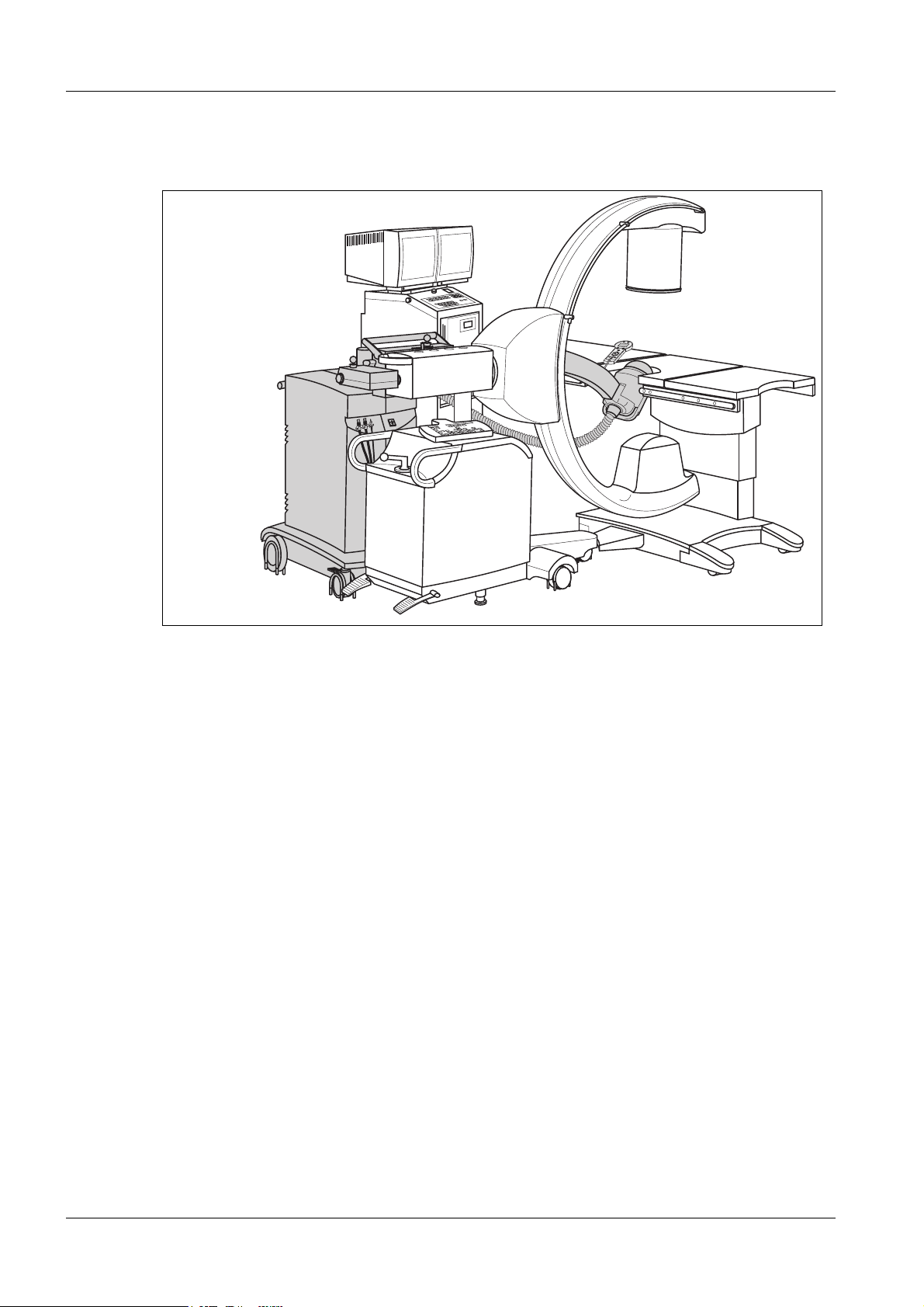
Components of a MODULARIS Uro Plus system 1
B
D
F
A
LITHOSTAR MODULARIS
SIREMOBIL Iso-C
Fig. 1
Imaging module:
A: SIREMOBIL ISO-C basic unit with X-ray generator
B: Sirecon 23-3 HDR image intensifier
C: X-ray tube with integrated collimator
D: Trolley with monitor and Memoskop digital memory
H
G
E
C
Table mo dule:
E: MODULARIS Uro patient table
ESWL module:
F: LITHOSTAR MODULARIS
G: Shock wave head with shock wave system C
H: Manual control
Options: (not shown)
SIRECUST ECG triggering
SONOLINE Prima ultrasound device (general monitoring)
e.g. Multispot 2000 multi-format camera / laser camera connection)
MODULARIS Uro Plus SPL1-130.041.01 Page 2 of 6 Siemens AG
Rev. 01 09.98 TD SD 24 Medical Engineering
Page 7
Introduction 1 - 3
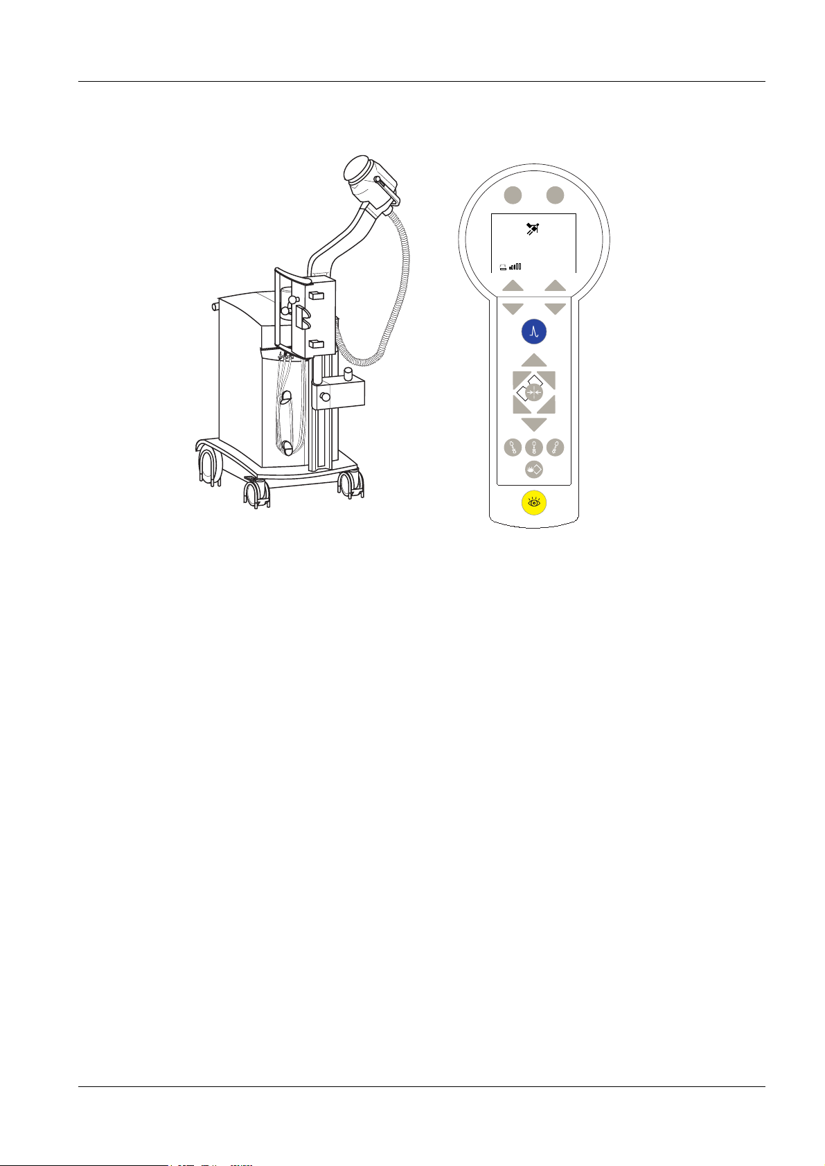
LITHOSTAR MODULARIS overview 1
1
3
8
4
LITHOSTAR MODULARIS
1. Shock wave head
5
6
Report Menu
___0
P Energy
0,1
2
7
2. Supply line
3. Support arm
4. Basic unit with
- control unit with chip card reader
- shock wave generator
- cooling unit with hydraulic control
- power supply
- control cable to SIREMOBIL Iso-C
- control cable to MODULARIS Uro table
- control cable to SIRECUST ECG unit
5. Manual control with LCD display
6. Focus measurement device (focus phantom)
7. C-arm angulation motor (+/- 20 degrees)
8. Coupling and locking unit to the SIREMOBIL ISO-C
Options: (not shown)
- SIRECUST ECG triggering
- ultrasound general monitoring
Siemens AG SPL1-130.041.01 Page 3 of 6 MODULARIS Uro Plus
Medical Engineering Rev. 01 09.98 TD SD 24
Page 8
1 - 4 Introduction
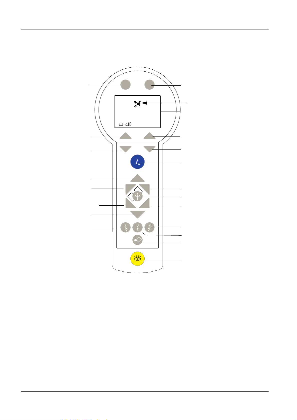
Manual control with LCD display and selection keys 1
Multifunctional use
Multifunctional use
depending on
the display
Move table upward
Move table left
Move table towards head-end
or foot-end (dep. on position)
Move table down
S1
Report Menu
S2
___0
0,1
P
Energy
S3
S5
S6
S4
Multifunctional use
Patient position*
LCD display
Multifunctional use
depending on
the display
Shock wave release
Move table towards head/foot end
Litho basic position
Move table right
C-arm angulation -20°
The manual control comprises the LCD display with buttons for controlling the shock wave
system, and buttons for controlling the table movement or C-arm for localization. There
are additional buttons for radiation release and image storage.
* Orientation: At the beginning of the treatment, the user determines the "patient position"
in the display. The shock wave head is the point of reference. The travel direction of the
table then depends on the kidney to be treated. Headward or footward can be reversed,
depending on the table orientation.
C-arm angulation +20°
C -arm 0° position
Image memory
Release fluoroscopy
MODULARIS Uro Plus SPL1-130.041.01 Page 4 of 6 Siemens AG
Rev. 01 09.98 TD SD 24 Medical Engineering
Page 9
Introduction 1 - 5
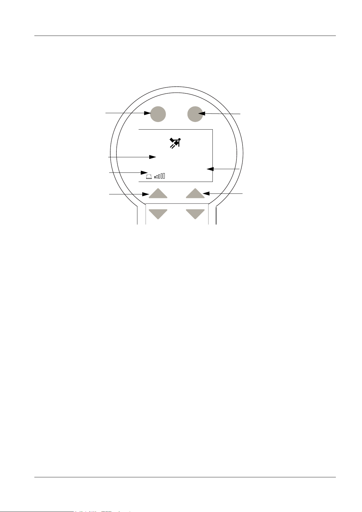
Menu displays 1
After system startup
Select
“Report”
Report Menu
Shock wave
count
Display
“Coupling Pressure”
Select
“Coupling Pressure”
Coupling pressure: 5 levels are selectable. Gel position if none are selected.
Energy levels: selectable from 0.1 to 8.0. After level 4, a warning appears
___0
0,1
P
Coupling pressure is continuously adjustable
after switching to the selection menu.
"kidney application exceeded!"
Energy
Select
“Menu”
Display
"maximum
energy level or
pulse/min for
kidney application
exceeded"
Display
shock wave
energy
Select
“Energy Level”
Siemens AG SPL1-130.041.01 Page 5 of 6 MODULARIS Uro Plus
Medical Engineering Rev. 01 09.98 TD SD 24
Page 10
1 - 6 Introduction
Selection menu 1
Example:
select
“position”
Back Back
Selection
> Position
Pulse/min
ECG-Trig.
P-control
Back Back
Selection
...
Rinsing
> Brightness
The selection menu is used to select and set the parameters displayed above.
- patient position - shock wave release frequency - ECG triggering
- P regulation - rinse coupling circuit -brightness set
(LCD display)
Refer to the next chapter for additional service-specific details on the menus.
MODULARIS Uro Plus SPL1-130.041.01 Page 6 of 6 Siemens AG
Rev. 01 09.98 TD SD 24 Medical Engineering
Page 11
Function Overview 2
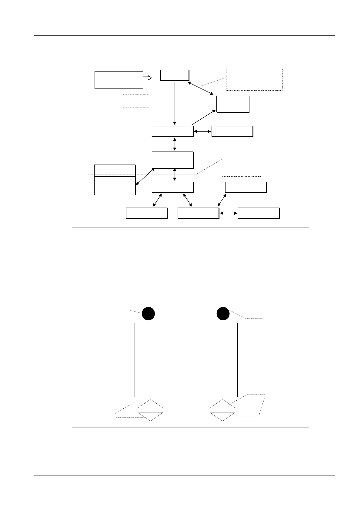
f
Using menus in the display 2
2 - 1
Chipcard not ok, return by
means of Cardchange or. I
chipcard is acceppted
Chipcard-
Status
Therapydata
These Menues are
only accessable for
Service Technic.
Error table
Pulse counter
Fig. 1
After Turn on
Chipmenu
Chipmenu f.
Goldcard
Startup
Chipcard
okay
Therapymenu
Selection
Service-Menu
System dataDate
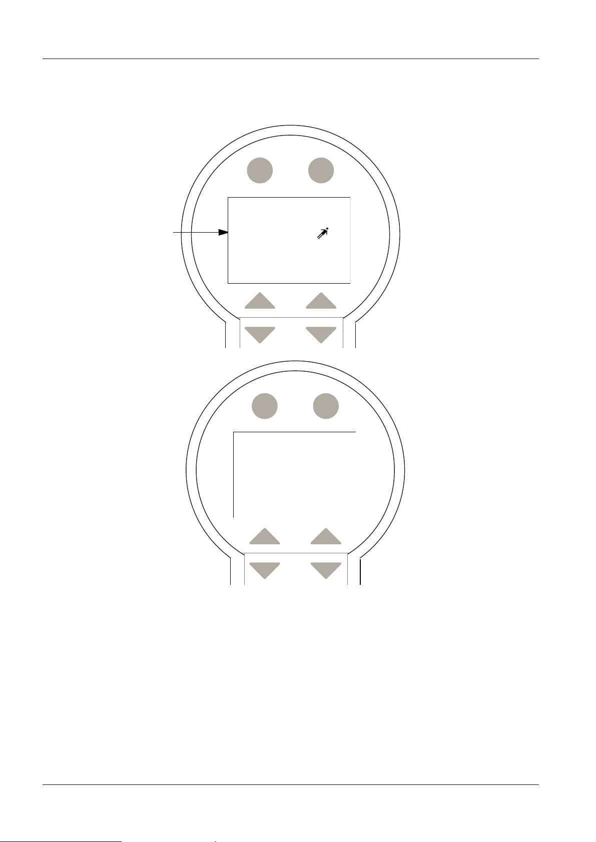
Once the system successfully starts up, the therapy menu is displayed.
If this is a pay-per-use system, the user can access the chip menu in order to check the
current chip data.
For Goldcard systems, the chip menu is only accessible in service mode.
(Service mode: switching S2 on board D3.)
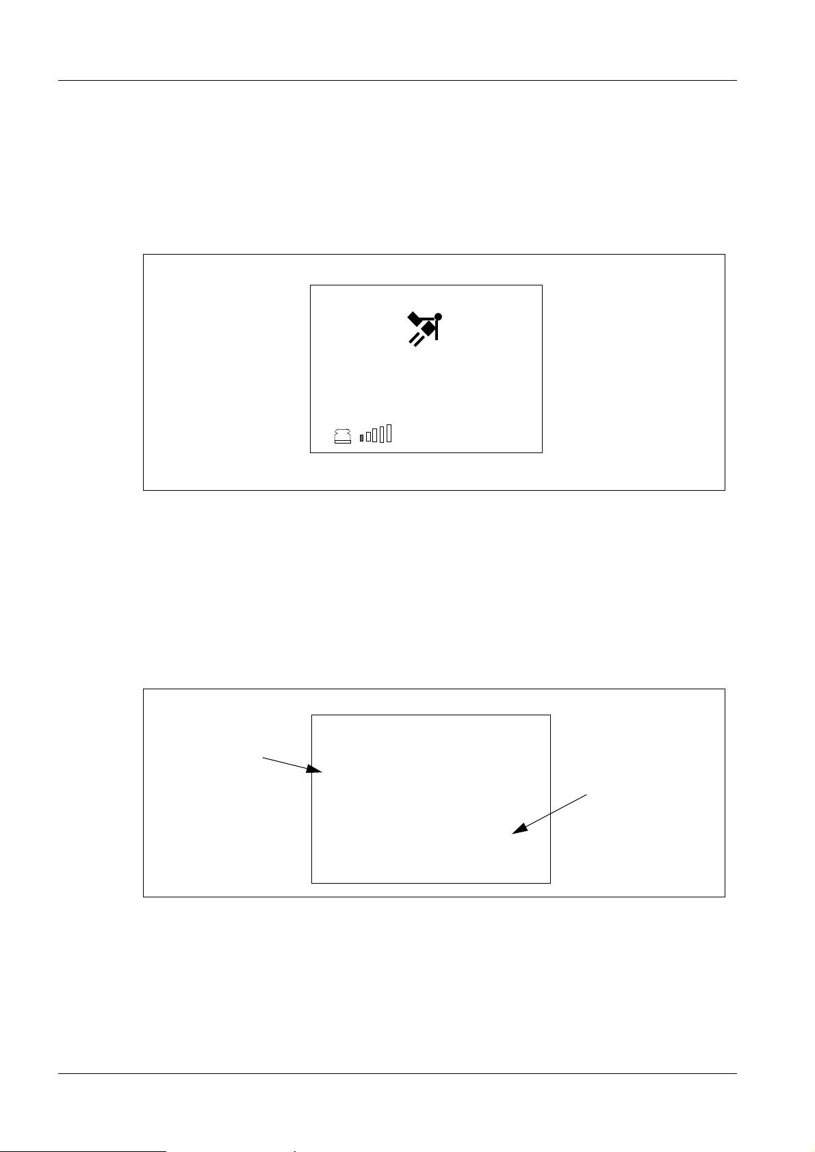
System start-up 2
S1
S2
SIEMENS
MODULARIS
S3 + S4
Fig. 2
If the system uses the Siemens configuration, the above will be displayed once the
LITHOSTAR MODULARIS is switched on. The keys on the manual control unit are
S5 + S6
Siemens AG SPL1-130.041.01 Page 1 of 6 MODULARIS Uro Plus
Medical Engineering Rev. 01 09.98 TD SD 24
Page 12
2 - 2 Function Overview
blocked and cannot be activated until the start-up process is completed. After an automatic water circulation cycle in the coupling circuit (length of time approx. 18 sec), the
chip card interface is checked. If the chip card is in order, the therapy menu will appear. If
the chip card is empty, invalid, or defective, the user must take appropriate action (refer to
chip card interface).
The therapy menu 2
Report Menu
___0
0,1
Fig. 3
P
Energy
Functions:
Í Increase or decrease the energy level (refer to shock wave system).
Í Increase or decrease the coupling pressure (refer to shock wave system).
Report: Press this key to display the therapy data. Pressing the Reset key for more than
one second resets the therapy data, and returns to the therapy menu.
Reset Back
Average value
E E Pulse
Ø max
3,8 4,7 3712
Only with
a pay per use
system
remaining units: 211 196
Fig. 4
MODULARIS Uro Plus SPL1-130.041.01 Page 2 of 6 Siemens AG
Rev. 01 09.98 TD SD 24 Medical Engineering
Page 13

Function Overview 2 - 3
e 1
e 2
The selection menu 2
There are two display pages for this menu.
Goldcard Pay-per-use or Service on
Back Back
Selection
>
Position
Pulse/min
ECG-Trig .
P-control
Back Back
Selection
> Brightness
Fig. 5
Functions:
...
Rinsing
Back Back
Selection
Position
Pulse/min
> ECG-Trig.
P-control
Back OK
Auswahl
Chipcard
>Rinsing
Brightness
Service
Pag
1
|
0
Pag
2
Í Pulse/min: 60/90120 shock waves per minute selectable (USA 2Hz fixed).
Í ECG - triggering: select on/off (option).
Í P-regulation: in steps or continuously selectable (refer to shock wave system).
The chip card menu depends on the chip card being used.
.
Goldcard
Return Eject
Chipcard
Return Eject
Type: LITHOCARD Gold
INIT-Counter: 1
Fig. 6
LITHOCARD 250 000
Remaining units: 122 234
Pay per use
Chipcard
Refer also to chip card interface.
Siemens AG SPL1-130.041.01 Page 3 of 6 MODULARIS Uro Plus
Medical Engineering Rev. 01 09.98 TD SD 24
Page 14

2 - 4 Function Overview
The service menu (English only)
2
Back Next
Service
> Set clock
Cooling unit
Coupling circuit
System data
Fig. 7
Back returns to the "selection menu".
Back Back
Service
Set clock
⇓
> Cooling unit
Coupling circuit
System data
fill
empty
Functions:
Í Set clock: set the time and date. Refer to control board D3
Í Cooling unit and coupling circuit: fill/empty the cooling circuit and the coupling cir-
cuit; use arrow keys to activate. Refer to shock wave system.
Í System data: also refer to control board D3, shock wave system, C-arm angula-
tion
Back Next
System data
Error table
Language
> Pulse counter
C-arm 0-Pos.
SW: VA00A / VA001
Fig. 8
MODULARIS Uro Plus SPL1-130.041.01 Page 4 of 6 Siemens AG
Rev. 01 09.98 TD SD 24 Medical Engineering
Page 15

Function Overview 2 - 5
Í Error log
Back Help
Error table
E14: xxxxxxxxxxxxxxxx
E56: xxxxxxxxxxxxxxxx
> E35: xxxxxxxxxxxxxxxx
E23: xxxxxxxxxxxxxxxx
E86: xxxxxxxxxxxxxxxx
Fig. 9
The error log lists the errors in the order of their occurrence, with the most recent at the
top of the list. Press Help for more detailed information. The last 100 errors are listed.
Back Reset
⇓
Pulse counter
system unit 1 543 846
shockwave head 534 357
⇓
Back Back
E35: Temperature of shock head too
high, please wait!
E14: xxxxxxxxxxxxxxxx
E56: xxxxxxxxxxxxxxxx
> E35: xxxxxxxxxxxxxxxx
E23: xxxxxxxxxxxxxxxx
E86: xxxxxxxxxxxxxxxx
Yes OK? No
Pulse counter
system unit 1 543 846
shockwave head 534 357
> capacitor 1 543 846
spark gap 488 634
Fig. 10
Check the shock wave counter: displays the shock waves released with respect to the
individual components of the shock wave system.
Reset procedure: after pressing the reset key, a reconfirmation query appears (yes/no).
The total shock wave counter (system unit) cannot be reset.
> capacitor 0
spark gap 488 634
Siemens AG SPL1-130.041.01 Page 5 of 6 MODULARIS Uro Plus
Medical Engineering Rev. 01 09.98 TD SD 24
Page 16

2 - 6 Function Overview
Summary: 2
This chapter describes the most important system operations for service with respect to
the therapy, selection, and service menu, and categorizes the various main functions.
Í increase or decrease the energy level (refer to shock wave system)
Í increase or decrease the coupling pressure (refer to shock wave system).
Í Pulse/min: 60/90120 shock waves per minute selectable (USA 2Hz fixed).
Í ECG - triggering: select on/off.
Í P-regulation: in levels or continuously selectable (refer to shock wave system).
Í Set clock : set the time and date (refer to control board D3)
Í Cooling unit and coupling circuit: filling or emptying the cooling circuit and the
coupling circuit, activated via the arrow keys (refer to shock wave system).
The main functions of the system will now be illustrated and discussed using a block diagram.
MODULARIS Uro Plus SPL1-130.041.01 Page 6 of 6 Siemens AG
Rev. 01 09.98 TD SD 24 Medical Engineering
Page 17

Block diagram 3
3 - 1
M15
Keyboard
LCD-display
M17
Chipcard
modul
D1
power supply
D3/PC104
µP-control
M12
Shockwave
generator
M14
Cooling and
coupling
control
M3
Shockwave
head
M2
C-arm
angulation
motor
MODULARIS
Uro
Examination
table
M18
ECG-unit
(Option)
SIRECUST
LITHOSTAR MODULARIS
Fig. 1 Block diagram of the LITHOSTAR MODULARIS
SIREMOBIL
ISO-C
Main system functions 3
• The operating and menu functions (already discussed in chapter 2 ) are extremely
important, since they affect almost all of the system functions. Location is M15 and
controller D3/PC104. The PC104 piggy-back board realizes a PC-based system.
• The main function of the system is to generate a shock wave starting with the release
key, and up to the point where the shock wave enters the patient’s body.
Components involved are: M15, controller D3/PC104, the shock wave generator with
high voltage generation M12, the shock wave head M3, the cooling and coupling system
M14, and M18 for ECG-triggered shock waves with the SIRECUST.
• Stone localization in the urological tract is achieved via motorized movement of the C-
arm M2 and the MODULARIS Uro table.
The imaging system is the SIREMOBIL ISO-C (FL or DR, etc.).
Siemens AG SPL1-130.041.01 Page 1 of 2 MODULARIS Uro Plus
Medical Engineering Rev. 01 09.98 TD SD 24
Page 18

3 - 2 Block diagram
• The chip card module enables "pay per use" operation; in other words, it contains a
certain number of shock waves which the user can release. A goldcard system is also
available. The chip card module is covered, so that the card is not accessible from the
outside.
MODULARIS Uro Plus SPL1-130.041.01 Page 2 of 2 Siemens AG
Rev. 01 09.98 TD SD 24 Medical Engineering
Page 19

System Start-up 4
4 - 1
internal
Tests
external
Tests
Power on
Initialisation of
control board
Activating pumps
for 2 seconds
Checking of
control switches
Coupling circuit
rinsing (18 sec)
HW-version test
RAM and power
supply test
Software check
System startup
SIEMENS
LITHOSTAR MODULARIS
start up
display
D3/PC104
µP
Stand by mode
Bericht Menü
___0
0,1
P
Therapy menue
Internal tests (initialization) 4
After switching on the software initializes the internal register, counters, I/O ports, interface circuits, etc. The system also checks the validity and functionality of the hardware
and software versions, the power supply, the memory circuits, the user software, and
much more. It also initializes the manual control.If an error occurs during this phase, an
error message will appear on the 7 segment display on the control board. Immediately
after switching on the system, the manual control displays "system start-up".
Energie
Siemens AG SPL1-130.041.01 Page 1 of 2 MODULARIS Uro Plus
Medical Engineering Rev. 01 09.98 TD SD 24
Page 20

4 - 2 System Start-up
External tests 4
During this phase of the start-up process, the manual control displays "start-up display".
To tear off (start up) the cooling and coupling circuit pumps, they are switched on for
approximately 2 seconds. Then the program activates the water circulation cycle in the
coupling circuit, which takes approximately 18 seconds. This procedure removes any air
bubbles which may be present in the coupling bellows.
The "therapy menu" is displayed, indicating that the system start-up is complete. If there
are no more activities, the system is in normal mode.
In normal mode, the processor system checks functions such as:
power supply, correct pump function, water temperature and water pressure, etc. Any
errors will be displayed on the manual control display.
Start-up after download and new control board D3 4
The service switch on D3 is set to "on". After approximately 20-30 seconds, "0" is displayed on the 7-segment display. The switch-on message is "E00".
The following error messages are normal:
E53,E80,E81,E82,E83,E86 internal data invalid, initialized at the first start-up.
These messages will no longer appear once another reset is performed, and the system
will start normally, as described above.
MODULARIS Uro Plus SPL1-130.041.01 Page 2 of 2 Siemens AG
Rev. 01 09.98 TD SD 24 Medical Engineering
Page 21

The shock wave system 5
Overview 5
5 - 1
M15
Keyboard
M11/D1
power supply
Fig. 1 Circuit diagram of the shock wave system
M13/D3/PC104
µP control board
M12
Shockwave
generator
Temperature / Pressure
M14
Cooling and
coupling circuit
The shock wave system comprises the following components:
• the shock wave components M12 and M3.
• the cooling circuit M14.
• the coupling circuit M14.
M3
Shockwave head
Cooling
Coupling
• the controller D3/PC104
• the release switch on manual control M15.
The objective is to generate a shock wave in shock wave head M3, which then enters the
patient’s body. The stone must be positioned in the focus of the shock wave head, and is
fragmented as a result of the shock wave pressure.
Shock wave generation is based on the electrodynamic principle. The discharge current
of a 1.2 µF capacitor flowing in a primary coil causes the metal membrane in the secondary coil to deflect in the axial direction. This creates an acoustic wave which is focused via
a synthetic lens.
The shock wave passes through a water-filled coupling bellows and then enters the
patient’s body. The water pressure and flow rate determine optimal coupling. The water
pressure in the coupling circuit is constantly monitored.
Generating shock waves creates heat which must be cooled via a cooling circuit so that
the coupling water does not overheat and burn the patient’s skin. Furthermore, the static
and dynamic water pressure in the cooling circuit presses the metal membrane (secondary coil) onto the primary coil, in order to provide optimized energy transfer.
The shock wave intensity is varied (pressure at the focus) in the primary coil of the shock
wave head.
Siemens AG SPL1-130.041.01 Page 1 of 12 MODULARIS Uro Plus
Medical Engineering Rev. 01 09.98 TD SD 24
Page 22

5 - 2 The shock wave system
Fokus
120.3**
Aperturwinkel
55.2° **
Ø164.5*
Ø125.2*
(The shock wave head 5
Wasseranschluß
Kühlkreis
Water connector
Cooling circuit
Wasseranschluß
Gewicht Stoßwellenkopf C incl.
Wasserfüllung: 5,0 kg
Focus
Kühlkreis
Water connector
Cooling circuit
Koppelbalg
Coupling bellows
Ankoppelbereich
Linse
Plastic Lense
Membrane
(secundary coil)
Vorlaufstrecke
Stoßwellen
quelle
shock wave source
ceramic body
with
primary coil
Hochspannungsanschluß
hightension
connector
Fig. 2 Layout of the shock wave head and coupling bellows (does not correspond to the original MODULARIS shock wave
head)
coupling circuit
water support
MODULARIS Uro Plus SPL1-130.041.01 Page 2 of 12 Siemens AG
Rev. 01 09.98 TD SD 24 Medical Engineering
Page 23

The shock wave system 5 - 3
The cooling and coupling circuit hydraulics 5
Fig. 2 shows the principle construction of the shock wave head. The following provides
additional information on the shock wave head with respect to the cooling and coupling
circuit.
12
Shockwave
head(SWK)
11
P
Coupling
circuit
blue
P
max
S50
red
3b
green
yellow
Normal duty cycle
Filling duty cycle
M2
2
S51
P
min
5
Cooling
circuit
1
8
Y2
9
4
S52
min. water level
6
3a
M1
Y1
7
10
Fig. 3 Circuit diagram of the cooling and coupling circuit
1) Druckschalter/Pressure switch (p min) 6 Druckausgleichsbehälter / Pressure
balance container
2 Druckschalter /Pressure switch(p max) 7 Wasserfilter / Water filter
3a Schlauchpumpe / Peristaltic pump
(Cooling circuit)
3b Schlauchpumpe / Peristaltic pump
(Coupling circuit)
8 Kugelhahnventil / Ball valve (emp-
tying cooling circuit) manual
9 Magnetventil / Solenoid valve (Fill-
ing cooling circuit)
4 Schwimmerschalter / Floating switch 10 Wasserbehälter / Water supply
5 Belüftungsventil / Degassing valve
11 Entlüftungsventil / Degassing valve
(Coupling bellows)
n.a. 12 Kühlgerät / Cooling unit
Siemens AG SPL1-130.041.01 Page 3 of 12 MODULARIS Uro Plus
Medical Engineering Rev. 01 09.98 TD SD 24
Page 24

5 - 4 The shock wave system
The cooling circuit 5
Objective:
• to cool the shock wave source; the water temperature in the coupling system may not
exceed 41°C under any circumstances.
• to generate static water pressure in the cooling circuit, which presses the membrane
(secondary coil) against the primary coil (embedded in the ceramic body), in order to
provide optimal energy transfer.
Note: The shock wave head is designed so that the water flow causes dynamic pressure
to build up, therefore supply and return hoses must not be interchanged.
For temperature monitoring, two temperature sensors enclosed in a metal housing are
pressed against the ceramic body of the shock wave head by a compression spring. Controller board D3 monitors the signal forwarded via an A/D converter in the µP microprocessor-controlled system.
The cooling circuit pump switches on:
"with the start of shock wave release, or if the temperature is too high".
Temperature cooling pump
Temp<5°C release blocked, error message "Sensor defective"
5°C<Temp<40°C cooling pump on: velocity 60%
40°C<Temp<60°C cooling pump on: velocity 70%
60°C<Temp<80°C cooling pump on: velocity 80%
Temp>80°C cooling pump on: velocity 80%, shock wave release
blocked, error "shock wave head overheated
Function: (refer to Fig.3/5-3)
Normal mode: the peristaltic pump 3a forces the warmed water coming from the shock
wave head (SWK) through the cooling unit 12 and then back through the shock wave
head, etc. The pressure balance container 6 equalizes the pressure variations in the cooling circuit. Pressure switches 1 and 2 monitor the acceptable pressure values.
Degassing valve 11 removes small air bubbles from the cooling circuit.
If the maximum pressure (780mbar) is exceeded for more than 3 s, the µP sends an error
message. If the minimum pressure is not reached, the 3-way valve 9 will switch to fill for
1s. In other words, water flows from water supply 10, through water filter 7, into the cooling circuit. After a pause of 2s, the µP checks the min switch. If the switch is not activated
yet, the filling process repeats, otherwise the filling process is completed. If the minimum
pressure is still not reached after 20 fill processes, the µP emits an error message: "leak
in system".
Filling and emptying: "possible in service mode only"
Ball valve 8 must be opened manually. In the service menu, select either fill cooling circuit
or empty cooling circuit. 3-way valve 9 switches over. Activate the pump via the manual
control. During the filling process, pump water into the cooling circuit until there are no
more air bubbles visible in the water return. The pump stops if the pressure switch
reaches max 2. If the pressure switch responds while the circuit is emptying, the pump will
continue to run.
MODULARIS Uro Plus SPL1-130.041.01 Page 4 of 12 Siemens AG
Rev. 01 09.98 TD SD 24 Medical Engineering
Page 25

The shock wave system 5 - 5
The coupling circuit 5
Objective:
The shock wave passes into the patient’s body via the flexible front part of the shock wave
head; the coupling bellows. It is extremely important that contact with the patient’s skin
surface is not interrupted, and that there are no air bubbles (due to total reflection).
Coupling can be done manually or automatically in five pressure levels, and is selected
via the manual control. Automatic means that a pressure sensor monitors the working
range of the selected pressure level and regulates the water fill in the coupling bellows.
3200mV
3200mV
2800mV
2400mV
1700mV
5
4
950mV
750mV Gelposition
1
pressure sensor (mV)
0
3
2
750mV Gelposition
pressure sensor (mV)
0
pressure steps
Fig. 4 Pressure levels selectable either continuously or in 5 levels. (pressure sensor output values in mV)
pressure manual
Function: (refer to Fig.3/5-3)
Normal mode: If automatic mode is selected, the peristaltic pump 3b pumps water into
the coupling bellows until the selected pressure level is reached (fill level of the shock
wave head).
In manual mode, the user selects the fill level of the coupling bellows by activating the
appropriate keys on the manual control. Pressing the key longer than 3 seconds changes
the pump velocity from v1 to v2.
When the water supply is pumped out, the electronics switch off the pump and an error
message is transmitted. Degassing valve 5 is closed.
Note: "rinse the coupling circuit" can be selected via the manual control. This removes air
bubbles from the coupling bellows.
Filling and emptying: "only in service mode"
During filling, peristaltic pump 3b pumps via water filter 7. Degassing valve 5 is opened.
The filling process is completed when no more air bubbles are visible in the return. A
small hose is located in the coupling bellows, which is attached to the coupling bellows
and suctions out air bubbles.
Emptying follows the same principle; the motor is reversed and water is suctioned out.
Siemens AG SPL1-130.041.01 Page 5 of 12 MODULARIS Uro Plus
Medical Engineering Rev. 01 09.98 TD SD 24
Page 26

5 - 6 The shock wave system
Electrical circuit diagram of the cooling and coupling circuit: 5
X2.3
F5
T2
1,6AT
230V
X2.5
X2
M11
M14
12
X55 3
X52.1
X51.2
circuit
Cooling
M1
M
pump
2
3
X53.1
4
pump
circuit
Coupling
M2
M
2
filling
circuit
circuit
Cooling
Coupling
ventilation
Y1
Y2
Water
F> min
L
S52
container
filling level
P
0,78 bar
P max
S50
Cooling
switches
pressure
circuit
P
P min
0,18 bar
S51
2
X56.1
6
5
9
8
7
Cooling and coupling circuit
X7.
3
2
4
MK-
MK+
M13
J51
Motor
F2
Driver
3,15AT
+24V
D3
Fig. 5 Circuit diagram of the shock wave system
F3
MA-
MA+
Motor
Driver
3,15AT
+24V
5
J52
F4
6
+Y1
7
-Y1
3,15AT
+24V
8
+Y2
9
-Y2
X3.
9
5
6
3
2
P max
A
5V
P min
A
0V
Control board
MODULARIS Uro Plus SPL1-130.041.01 Page 6 of 12 Siemens AG
Rev. 01 09.98 TD SD 24 Medical Engineering
Page 27

The shock wave system 5 - 7
M1, M2: The two 24V pump motors are controlled via pulse-width modulation. That is,
motor output can be controlled between 0% and 100%.
The temperature, control, and starting current are monitored.---> refer to error messages.
Startup: Via the motor drive, the µP switches on pumps M1 and M2 at 100% for 2 seconds.
After that, M2 runs for 18 seconds at 70% in order to remove air bubbles from the coupling circuit (only in normal mode).This time is omitted in service mode.
Fuses F2, F3, F4: are monitored by the µP system.
Displays: MK+, MK-, MA+, MA- clockwise or counter-clockwise.
Measurement points: n.a.
Siemens AG SPL1-130.041.01 Page 7 of 12 MODULARIS Uro Plus
Medical Engineering Rev. 01 09.98 TD SD 24
Page 28

5 - 8 The shock wave system
The charging and high voltage circuit 5
230 V~
power
supply
evaluation
peak value
High tension charger
Idisch_max
KVact
KVact/2
CH0
CH1
10 Bit
control
error
CH2
ADC
max
KV
KV
I charge
KVnom
CH3
CH4
p
monitoring
CH5
Trigger-
U>Umax
230V~ 19 kV
f
elektronik
V
head
shockwave
Trigger
disch.
I
Cap/2
KV
Cap
KV
act
KV
generator
shock wave
capacitor
spark gap
230 V~
cooling unit
1,2µF
p
valve control
temp.sensor 1
temp.sensor 2
water level switch
motor control
STW
(HW)
230 V~
release
shock wave
Trigger
M13/D3
µP control
M15
keyboard
CLK
Shockwave
counter
Reset
energy steps
CS
Din
Dout
HVon
HVset
K1
Fig. 6 Circuit diagram: high tension charger and discharge circuit
MODULARIS Uro Plus SPL1-130.041.01 Page 8 of 12 Siemens AG
Rev. 01 09.98 TD SD 24 Medical Engineering
Page 29

The shock wave system 5 - 9
gg
gap
Function: (refer to Fig.6/5-8)
Prior to releasing a shock wave
the following parameters must be set via the manual con-
trol:
energy level release frequency ECG triggering on/off
For "pay-per-use" systems, a valid chip card must be available.
The shock wave release key on manual control M15 activates relay K1 on controller board
D3. There, the switch signal is coupled with the hard-wired software-controlled process.
This provides added protection against unintentional shock wave release in cases of malfunction.
Objective: charging the 1.2µF capacitor in the shock wave generator with the energy
level corresponding to the KV value, and then discharging it via the primary coil of the
shock wave head.
The HVon (high voltage on) and the frequency coded HVset (nominal KV) begin the
charging process (charge start). The 1.2 µF capacitor is charged to this nominal value.
Control D3 constantly monitors the KV nominal voltage via the A/C converter. The charging process is complete when the KV nominal value is reached.
KV
act
primary coil
secundary
coil
KV
charge start
Spark gap
1,2 µF
Capacitor
KV
= KV
act
nom
charge end >
tri
Focus
Shock
wave head
time
er to spark
Fig. 7 Shock head and charging principle
Siemens AG SPL1-130.041.01 Page 9 of 12 MODULARIS Uro Plus
Medical Engineering Rev. 01 09.98 TD SD 24
Page 30

5 - 10 The shock wave system
Control board D3 now begins the discharge process, and generates a trigger signal to
ignite the spark gap. Its function is similar to an electrical switch. During the abovedescribed charging and discharging process, control board D3 constantly monitors such
important parameters as:
• the total capacitor voltage KVact
• half of the capacitor voltage KVact/2
• the charging current I charge
• the discharge current I discharge
Using these values, the µP immediately recognizes a short in the capacitor, a loss in
capacitance or an error in igniting the spark gap.
Special note:
After 500 shock waves, the µP automatically stops the release, in order to remind the user
to check the focus. Continuation is only possible by opening and closing the release
switch.
Shock wave release is interrupted when exiting the main menu.
The energy level value ranges from 0.1 to 8.0. The maximum required energy for treatment of the kidneys is 4.0; therefore a warning appears on the display for levels above
this value. The auto-repeat function is not available between 4.0 and 4.2.
In free-running mode , the shock wave frequency can be set to 60, 90, and 120 pulse/min.
In the kidney area, the frequency can be set only up to 90 P/min. If 120 P/min is set, it will
be automatically reduced (fixed to 120 P/min in the USA).
In service mode, the release rate is limited to 15 shock waves/minute, and a chip card is
not required.
The ECG triggered shock wave release depends on the patient’s QRS signal. The shock
wave is released when the heart muscle enter the diastolic phase. The release rate must
not exceed the set free-running rate.
If a QRS signal is no longer detected for more than 2 seconds, the system will emit an
error message.
MODULARIS Uro Plus SPL1-130.041.01 Page 10 of 12 Siemens AG
Rev. 01 09.98 TD SD 24 Medical Engineering
Page 31

The shock wave system 5 - 11
P
M3
Stoßwellenkopf /
Shock wave head
and
M12
1,2µF Spark Gap
charging control
for shock wave head
High tension power supply
X2
X2.1
X2.2
M13
F4
8AT
230V
T2
Fig. 8 Circuit diagram of the charging / energy unit
D1
M11
FOC
(fibre optic cables)
U1
out
D
D3
U2
on
HV
U3
set
HV
U4
Trigger
U5
CLK
U6
CS
U7
in
D
X2
X8
about temperature and pressure
see service program for more information
Siemens AG SPL1-130.041.01 Page 11 of 12 MODULARIS Uro Plus
Medical Engineering Rev. 01 09.98 TD SD 24
Page 32

5 - 12 The shock wave system
Interface between D3 and M12 5
The control signals between D3 and M12 are galvanically separated by routing them via
fiber optic cables. "Active high" indicates that the transmission diode (LED) for the
receiver is active.> LED on
Explanation (with respect to M12):
Input
HV on: switch-on signal for the charging current circuit; high voltage on; LED
on
HV set nominal voltage frequency encoded; (1KHz = 1 KV) max 19.3 KV
Trigger trigger pulse to the ignition transformer; LED on
CLK synchronization of A/C converter and µP system
CS chip select; start A/C conversion; LED on.
D in data input A/C converter
Output:
D out data output A/C converter.
General:
For the charging/energy unit, only the spark gap can be replaced; all other malfunctions
require a complete replacement.
MODULARIS Uro Plus SPL1-130.041.01 Page 12 of 12 Siemens AG
Rev. 01 09.98 TD SD 24 Medical Engineering
Page 33

Table operation and interface 6
Overview 6
6 - 1
Middle part
for Shockwave
application
Head end side
Base frame
Foot pedal
Insert
Tilting control
Hand control
Lifting column
Foot end side
Radiolucent
middle part
z
y
x
Foot switch
Base frame extension
Fig. 1 Overview of table operation
The MODULARIS Uro patient table is used for the following medical applications:
• urological diagnostics and endourology
• extracorporeal shock wave lithotripsy
• prostate therapy
Four movement axes are available for positioning the patient:
• patient table toward the head-end, foot-end
• transverse patient movement
• upward and downward movement
• table tilt
Siemens AG SPL1-130.041.01 Page 1 of 4 MODULARIS Uro Plus
Medical Engineering Rev. 01 09.98 TD SD 24
Page 34

6 - 2 Table operation and interface
Manual control
table in litho basic position
lithotripsy mode on/off
on: lithotripsy mode selected
flashing: table not in
litho basic position
Fig. 2 Overview of patient table operation
Lithotripsy mode on/off: the system limits the table’s range of motion, due to the fact
that in the working position, the shock wave head could collide with the tabletop. Millimeter step mode is also possible in this operating mode .
Litho basic position: After selecting the lithotripsy mode, pressing this key causes the
tabletop to move into the basic position. The display light flashes until the basic position is
reached. The same key is also on the LITHOSTAR MODULARIS manual control. As long
as the LED is flashing, the basic position is not reached yet.
Prostate therapy mode: all table movements are blocked in this operating mode.
prostate therapy mode on/off
on: prostate therapy mode selected
MODULARIS Uro Plus SPL1-130.041.01 Page 2 of 4 Siemens AG
Rev. 01 09.98 TD SD 24 Medical Engineering
Page 35

Table operation and interface 6 - 3
Interface between LITHOSTAR and patient table
mains
power supply
D3
X27 X1
Fig. 3 Block diagram of table control
D1
Hand control
Foot switch
LITHOSTAR
interface
Table control
B
A
C
2
6
3
5
4
5
1
6
Drive AM1/S1
vertical movem.
Drive AM2/S2
longitudinal
movement
Drive AM3/S3
table transverse
Drive AM4/S4
table tilt
The patient table movement is controlled with the LITHOSTAR MODULARIS manual control via the connection X27-X1 from D3 to D1.
The signals for the table movement for each axis (one motor) are encoded via two logical
lines.
Line 1 Line Movement
00stop
10forward
01backward
11stop
Tab. 1
In addition, there is also a toggle line, which must change its logical status every 40 ms if
the table is activated. If there is no change within 100 ms, movement will stop. Each motor
is encapsulated and water resistant. There is a limit switch for each end stop. In case of
error, the entire drive must be replaced. In addition, micro switches S1, S2, S3, and S4
are available for the litho basic position.
A, B, C are equal-access plug-in positions on the table operating panel. They can be
replaced for troubleshooting. 1, 2, 3 and 4 are the outputs for the motor. 5 and 6 are the
limit switch inputs for the basic position.
Siemens AG SPL1-130.041.01 Page 3 of 4 MODULARIS Uro Plus
Medical Engineering Rev. 01 09.98 TD SD 24
Page 36

6 - 4 Table operation and interface
M15
Keyboard
M13
D3
0
°
Fig. 4 Circuit diagram of table control with M15
serial
data
trans-
mission
X5
Circuit diagram:
Measurement points:none
EPLD
X27
MODULARIS
Uro(Table)
D1
X1
Control
Note: For more
details see table
wiring diagram.
In case of function errors, first check the various controls (M15, tableside control or footswitch) to determine whether it is an operating or motor function error.
MODULARIS Uro Plus SPL1-130.041.01 Page 4 of 4 Siemens AG
Rev. 01 09.98 TD SD 24 Medical Engineering
Page 37

SIREMOBIL ISO-C Interface 7
Circuit diagram
7 - 1
D30
SW release
K6 K13
V84 GN
V82 GN
N11 SIREMOBIL ISO-C
X11.2
xray on
X34.2
K2
+15V
X11.3
X34.3
X11.4
X34.4
K3
D3
0V
K2
K3
M13
K8
V83 GN
X11.1
ATB
X34.6
+24V
K11
0V
Angulationsbremse/
X11.5
X34.8
K4
+24V
K4
Angulation brake
mb2
X11.6
X34.9
M2
1 KOhm
X38.4
0V
X38.3
X38.2
X36.2
M
X36.3
MC -MC
+
+24V
X5.6
X5.7
X5
serial data
transmission
+20°
0°
-20°
M15
Fig. 1 Block diagram: ISO-C interface
Siemens AG SPL1-130.041.01 Page 1 of 2 MODULARIS Uro Plus
Medical Engineering Rev. 01 09.98 TD SD 24
Page 38

7 - 2 SIREMOBIL ISO-C Interface
Docking mechanism: Prior to docking the LITHOSTAR MODULARIS to the SIREMOBIL
ISO-C, two micro switches were activated, which are not included in the block diagram
(refer to ISO-C block diagram G5464 p.10/switch S4 and S.11/switch S3).
The switches block all brakes on the ISO-C. Moving the lifiting column is only possible
after opening the docking bracket for decoupling.
Start-up: if the "X-ray on" key is pressed during start-up, a warning and error message
will be transmitted. Shock wave release will be blocked until the key is released.
Functions:
Radiation release: The key on manual control M15 is marked with a fluoroscopy symbol,
but basically all available modes are usable. Software release signal K13 and hand signal
K6 (dual protection) are activated via relay K2 on board D30. K8 deactivates the hand
switch on the ISO-C.
Save fluoro image: K3 responds, as well as K11 on D30, whose contact activates the
ATB (Auf Tastendruck Bild) function on control board D1 on the ISO-C.
C-arm angulation (+20/-20°): pressing the key releases the angulation brakes (via relay
K4), and activates the angulation motor in M2. The µP on D3 receives an actual value
position message from the 1 Kohm potentiometer. For purposes of testing, the angulation
motor can also be checked in the uncoupled position. After switch-on, the brakes remain
released until there has been motorized movement.
C-arm adjustment: adjustments are only possible in service mode. The movement velocity is reduced. When the adjustment mode is de-selected, the current actual value of the
potentiometer is saved and used as the new mean position, as long as it is within the permissible tolerance range (short beep). Otherwise the default value will be used, and an
error message will be transmitted (C-arm out of adjustment).
Default value 5V. Tolerance +/- 1.0 V.
MODULARIS Uro Plus SPL1-130.041.01 Page 2 of 2 Siemens AG
Rev. 01 09.98 TD SD 24 Medical Engineering
Page 39

The chip card system 8
Goldcard system 8
When a goldcard system is started for the first time, a counter is activated and a code is
set so that the card cannot be used in other systems. The card is checked during start-up
and at specific intervals during operation. The user cannot see the Goldcard, i.e., no
counter status and no messages with respect to the card.
Pay per use system 8
The system can be started without the chip card. The card is checked during start-up or
after insertion. Counter status is displayed in the main menu. The chip card can be
ejected via the menu. During therapy, the counter status is decremented. When the chip
card counter reaches less than 5000, a message is displayed, and the counter status
flashes. If the user inserts a new card, all remaining units from the old card will be transferred to the new one.
The counter status is updated before the card is ejected.
Service
8 - 1
Follow the specified procedure when replacing the D3 (PC 104) board (refer to Service
Instructions).
Chip card trace (available with future software versions)
A log of the last 50 chip cards in case:
...the chip card has an invalid status due to a defect, and the remaining units need to be
calculated.
...the customer questions the units logged.
The following data is required, and can be called up with the service PC:
number of logged units, serial number of the card, number of units the last time it was
ejected, date it was last ejected, and shot count for the system.
The chip card interface
Serial interface RS 232. COM 1 of the PC 104 board is used and connected via flat cable
to control board D3.
During system start-up and operation, a function test is performed. In case of error, the
entire reading unit must be replaced.
Siemens AG SPL1-130.041.01 Page 1 of 2 MODULARIS Uro Plus
Medical Engineering Rev. 01 09.98 TD SD 24
Page 40

8 - 2 The chip card system
This page intentionally left blank.
MODULARIS Uro Plus SPL1-130.041.01 Page 2 of 2 Siemens AG
Rev. 01 09.98 TD SD 24 Medical Engineering
 Loading...