

Page 1
MODULARIS Uro Plus
Planning Guide
SP
System
MODULARIS Uro Plus
© Siemens AG 2004
The reproduction, transmission or
use of this document or its contents
is not permitted without express
written authority. Offenders will be
liable for damages. All rights,
including rights created by patent
grant or registration of a utility
model _or_ design,_are_ reserved.
English
Print No.: SPL1-130.891.03.02.02 Doc. Gen. Date: 07.05
Replaces: SPL1-130.891.03.01.02
Page 2

0 - 2 Revision
Chapter Page Revision
all all 01
all all 02
Document revision level
The document corresponds to the version/revision level effective at the time of system delivery.
Revisions to hardcopy documentation are not automatically distributed.
Please contact your local Siemens office to order current revision levels.
Disclaimer
The installation and service of equipment described herein is to be performed by qualified personnel
who are employed by Siemens or one of its affiliates or who are otherwise authorized by Siemens or
one of its affiliates to provide such services.
Assemblers and other persons who are not employed by or otherwise directly affiliated with or authorized by Siemens or one of its affiliates are directed to contact one of the local offices of Siemens or
one of its affiliates before attempting installation or service procedures.
MODULARIS Uro Plus SPL1-130.891.03 Page 2 of 4 Siemens AG
Rev. 02 07.05 CS SD 21 Medical Solutions
Page 3

Contents 0 - 3
Page
1 _______General Notes _________________________________________________ 1 - 1
General Notes . . . . . . . . . . . . . . . . . . . . . . . . . . . . . . . . . . . . . . 1 - 1
Safety . . . . . . . . . . . . . . . . . . . . . . . . . . . . . . . . . . . . . . . . . . 1 - 2
MODULARIS "Litho Configuration" (partial illustration) . . . . . . . . . . . . . . . . . 1 - 3
MODULARIS "UltraLith Configuration" . . . . . . . . . . . . . . . . . . . . . . . . . 1 - 3
Illustration of MODULARIS Uro Plus Components . . . . . . . . . . . . . . . . . . . 1 - 4
Possible Configurations:. . . . . . . . . . . . . . . . . . . . . . . . . . . . . . . . . 1 - 5
Transmobile MODULARIS Uro Plus in a "Litho Configuration" . . . . . . . . . . . . . 1 - 5
Litho Share . . . . . . . . . . . . . . . . . . . . . . . . . . . . . . . . . . . . . . .1 - 5
2 _______Room Planning ________________________________________________ 2 - 1
MODULARIS Uro Plus Room Planning Recommendation, "Total Config." . . . . . . . 2 - 1
MODULARIS "Litho Configuration" Room Planning Recommendation . . . . . . . . 2 - 2
MODULARIS "UltraLith Configuration" Room Planning Recommendation . . . . . . . 2 - 3
MODULARIS "Endo Configuration" Room Planning Recommendation . . . . . . . . 2 - 4
ARCADIS Orbic Dimensions . . . . . . . . . . . . . . . . . . . . . . . . . . . . . . 2 - 5
Monitor Cart Dimensions . . . . . . . . . . . . . . . . . . . . . . . . . . . . . . . . 2 - 6
SONOLINE G20 with Monitor . . . . . . . . . . . . . . . . . . . . . . . . . . . . . . 2 - 7
Patients monitor Dimensions . . . . . . . . . . . . . . . . . . . . . . . . . . . . . . 2 - 7
LITHOSTAR MODULARIS Dimensions . . . . . . . . . . . . . . . . . . . . . . . . 2 - 8
LITHOSTAR MODULARIS . . . . . . . . . . . . . . . . . . . . . . . . . . . . . . . 2 - 9
MODULARIS Uro Dimensions . . . . . . . . . . . . . . . . . . . . . . . . . . . . 2 - 10
MODULARIS MUT . . . . . . . . . . . . . . . . . . . . . . . . . . . . . . . . . . 2 - 11
3 _______Preparation for Installation _______________________________________ 3 - 1
Recommendation for On-site Electro Installation (Application Group 1) . . . . . . . . 3 - 1
Recommendation for On-site Electro Installation (Application group 2). . . . . . . . . 3 - 2
Floor Properties . . . . . . . . . . . . . . . . . . . . . . . . . . . . . . . . . . . . . 3 - 3
Stationary Water Installation (Recommendation) . . . . . . . . . . . . . . . . . . . . 3 - 4
4 _______System Connections ____________________________________________ 4 - 1
Cable Connections . . . . . . . . . . . . . . . . . . . . . . . . . . . . . . . . . . . 4 - 1
5 _______Technical Data _________________________________________________ 5 - 1
Electrical Data . . . . . . . . . . . . . . . . . . . . . . . . . . . . . . . . . . . . . 5 - 1
Weights and Heat Dissipation . . . . . . . . . . . . . . . . . . . . . . . . . . . . . 5 - 1
Environmental Conditions . . . . . . . . . . . . . . . . . . . . . . . . . . . . . . . 5 - 2
Paint Colors . . . . . . . . . . . . . . . . . . . . . . . . . . . . . . . . . . . . . . .5 - 3
Additional Data . . . . . . . . . . . . . . . . . . . . . . . . . . . . . . . . . . . . . 5 - 3
Noise Development . . . . . . . . . . . . . . . . . . . . . . . . . . . . . . . . . . . 5 - 3
Packaging . . . . . . . . . . . . . . . . . . . . . . . . . . . . . . . . . . . . . . . .5 - 4
Gas Supply for KION Anesthesia Unit . . . . . . . . . . . . . . . . . . . . . . . . . 5 - 4
Siemens AG SPL1-130.891.03 Page 3 of 4 MODULARIS Uro Plus
Medical Solutions Rev. 02 07.05 CS SD 21
Page 4

0 - 4 Contents
Page
6 ______ Transportation Specifications ____________________________________ 6 - 1
Transport Pathways . . . . . . . . . . . . . . . . . . . . . . . . . . . . . . . . . . 6 - 1
Elevator Requirements . . . . . . . . . . . . . . . . . . . . . . . . . . . . . . . . 6 - 1
Transmobile Insert . . . . . . . . . . . . . . . . . . . . . . . . . . . . . . . . . . . 6 - 1
7 ______ Changes to Previous Version _____________________________________7 - 1
MODULARIS Uro Plus SPL1-130.891.03 Page 4 of 4 Siemens AG
Rev. 02 07.05 CS SD 21 Medical Solutions
Page 5

General Notes 1
1 - 1
General Notes 1
- With distribution of these revision level, all preceding planning guides, Speed Infos (PGs) and drafts
lose their validity.
- All layouts issued by the Planning Departments must bear a note referring to the installation and
delivery conditions of Siemens Medical Engineering. The installation and delivery conditions must
be submitted with the layouts.
- Unless otherwise specified, all dimensions are indicated in "mm".
- The symbol indicates a change (see revision status).
- Orientation points
Points specific to system components to which reference is made when positioning system
components to each other or in the room.
The isocenter of a radiographic system is always illustrated as the orientation point.
- Fixpoints
Clearly marked points on system components, installation ceiling, walls or floor on which cable
outlets are located.
Illustration in the drawings: octagon with letter/number-combination.
The cable lengths specify the maximum fixpoint distances and thus the maximum distances
between the individual system components.
- Room height
The room height is the distance measured from the top surface of the floor to the bottom surface of
the ceiling structural elements (Unistrut rails) (bottom surface of drop ceiling).
- Room lighting
According to DIN 68 68-57 (international standard in preparation), the lighting in rooms in which
image playback devices (monitors) are used for diagnosis, the following requirements must be
met:
adjustable, no anti-glare screen, reproducible adjustment of the lighting (e.g. dimmer with
scale),
no glare or reflection from windows, lights and light boxes in the standard working position of
the monitors.
Hotline + 49 (9191) 18 - 8080
Siemens AG SPL1-130.891.03 Page 1 of 6 MODULARIS Uro Plus
Medical Solutions Rev. 02 07.05 CS SD 21
Page 6

1 - 2 General Notes
Safety 1
- The provisions of the relevant fire safety regulations must be observed for the premises.
- The system has been developed according to EN 60601 - 1.
- Minimum dimensions (e.g. room heights, safety distances) indicated in the planning guides are
marked "min."
- Basic strength against electromagnetic sources of interference.
Result of lightning discharges.
The protection targets of the different lightning protection areas up to the unit connection are also
specified in the IEC 1024, DIN 48810, VDE 0675 and in the DEMVT recommendations.
MODULARIS Uro Plus SPL1-130.891.03 Page 2 of 6 Siemens AG
Rev. 02 07.05 CS SD 21 Medical Solutions
Page 7
General Notes 1 - 3
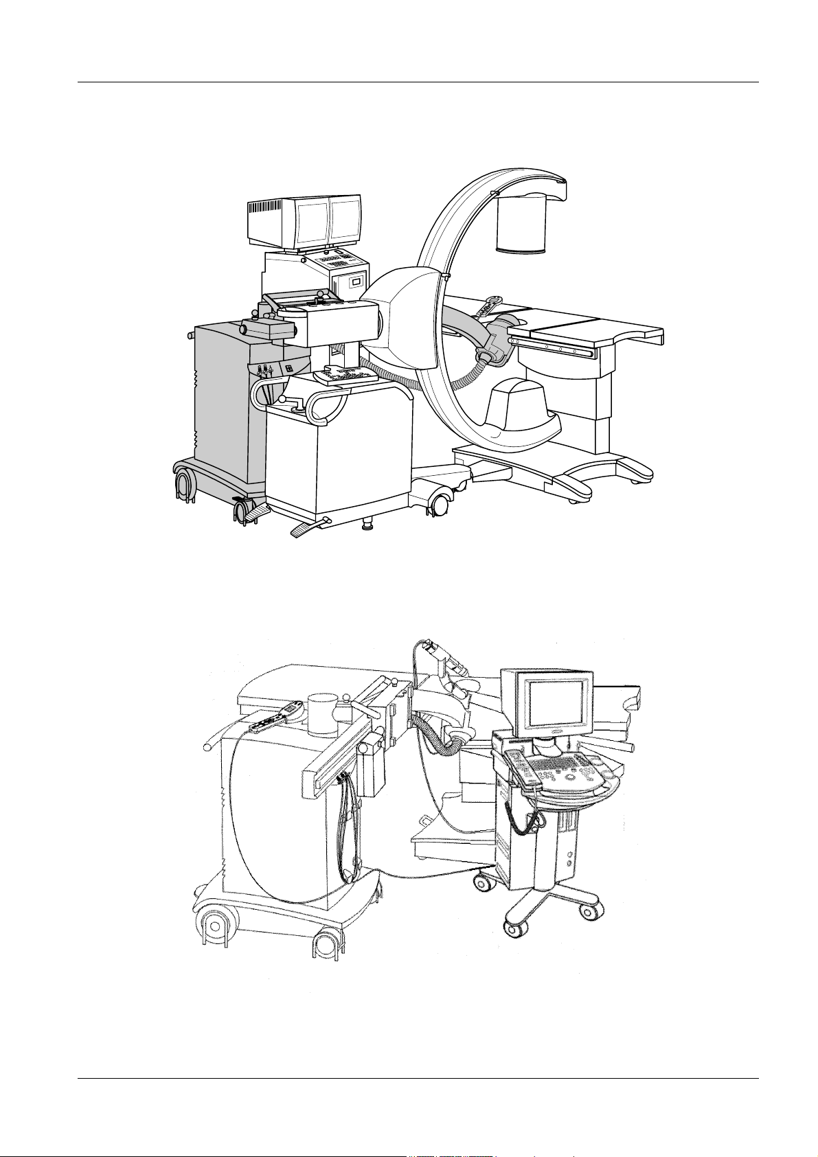
MODULARIS "Litho Configuration" (partial illustration) 1
MODULARIS "UltraLith Configuration" 1
Siemens AG SPL1-130.891.03 Page 3 of 6 MODULARIS Uro Plus
Medical Solutions Rev. 02 07.05 CS SD 21
Page 8
1 - 4 General Notes
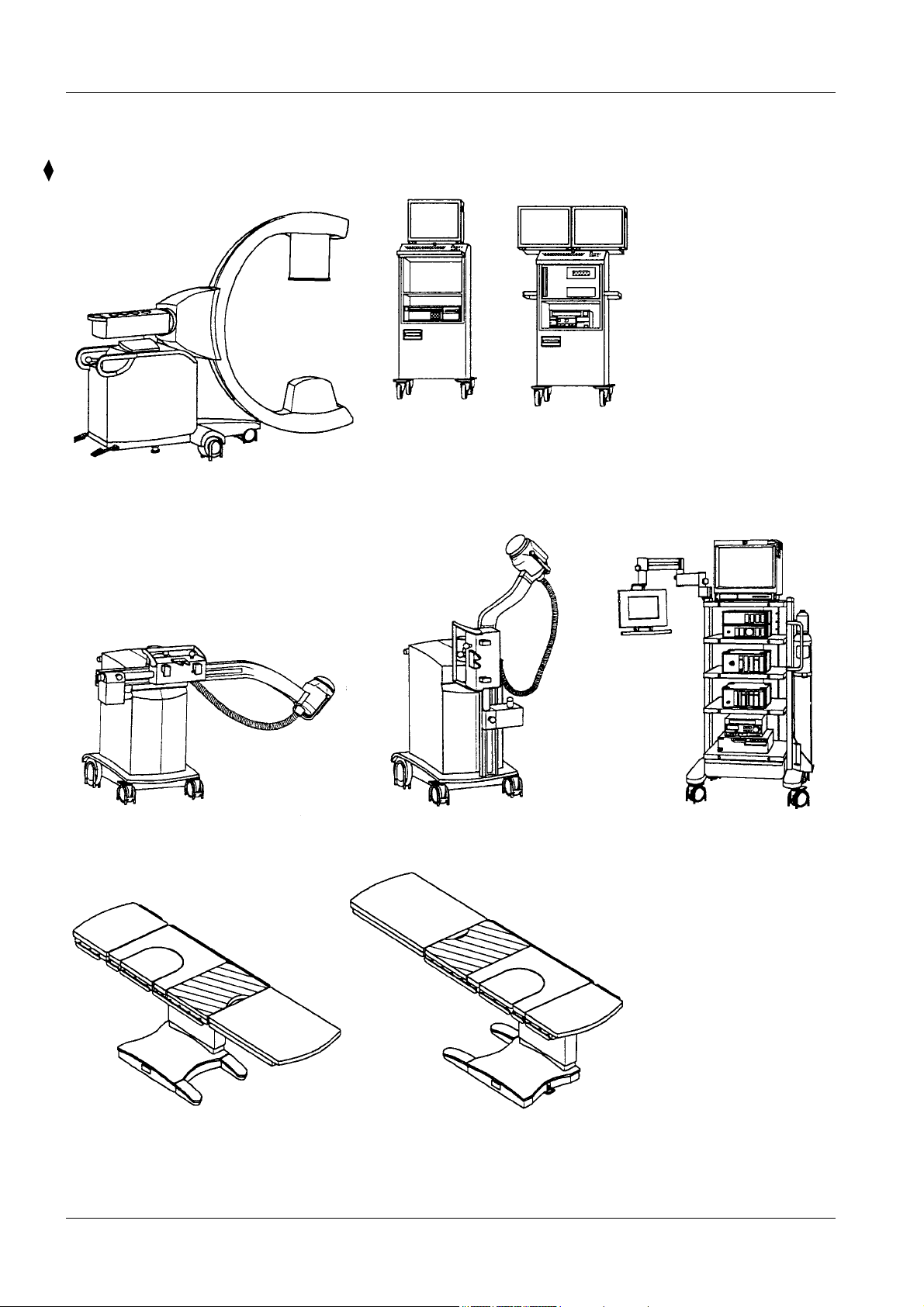
Illustration of MODULARIS Uro Plus Components 1
ARCADIS Orbic with monitor cart
MODULARIS MUT
LITHOSTAR MODULARIS
Operation position
MODULARIS Uro
Right
Park position
Left
MODULARIS Uro Plus SPL1-130.891.03 Page 4 of 6 Siemens AG
Rev. 02 07.05 CS SD 21 Medical Solutions
Page 9
General Notes 1 - 5
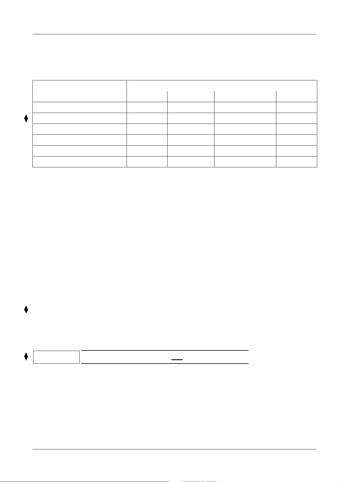
Possible Configurations: 1
MODULARIS Uro Plus Configuration
Litho UltraLith Endo Total
MODULARIS Uro XX X X
ARCADIS Orbic XOption X X
LITHOSTAR MODULARIS XX X
SONOLINE G20 Option X Option X
MUT MODULARIS XX
KION Option Option Option Option
Transmobile MODULARIS Uro Plus in a "Litho Configuration" 1
Transmobile means that the user transports the equipment in a vehicle to a hospital. In the hospital, the
equipment is assembled and treatment is performed. Then the equipment is prepared by the user for
transport and is transported to another hospital. The procedure is repeated there.
If the equipment of the MODULARIS Uro Plus platform needs to be transported, the User Instructions
SPL1-130.622.06 ... (Preparing the Vehicle) and
SPL1-130.622.05 ... (Preparations for Transport) must be observed.
Litho Share 1
Litho Share means that the LITHOSTAR MODULARIS can be coupled to different ARCADIS Orbic or
SIREMOBIL Iso-C units (they must be prepared for this) without having to readjust the isocenter, i.e.
the user purchases several SIREMOBIL Iso-C units and only one LITHOSTAR MODULARIS. Nothing
more needs to be noted for planning.
NOTE
Litho report functions only in one
ARCADIS Orbic.
Siemens AG SPL1-130.891.03 Page 5 of 6 MODULARIS Uro Plus
Medical Solutions Rev. 02 07.05 CS SD 21
Page 10

1 - 6 General Notes
This page intentionally left blank.
MODULARIS Uro Plus SPL1-130.891.03 Page 6 of 6 Siemens AG
Rev. 02 07.05 CS SD 21 Medical Solutions
Page 11
Room Planning 2
2 - 1
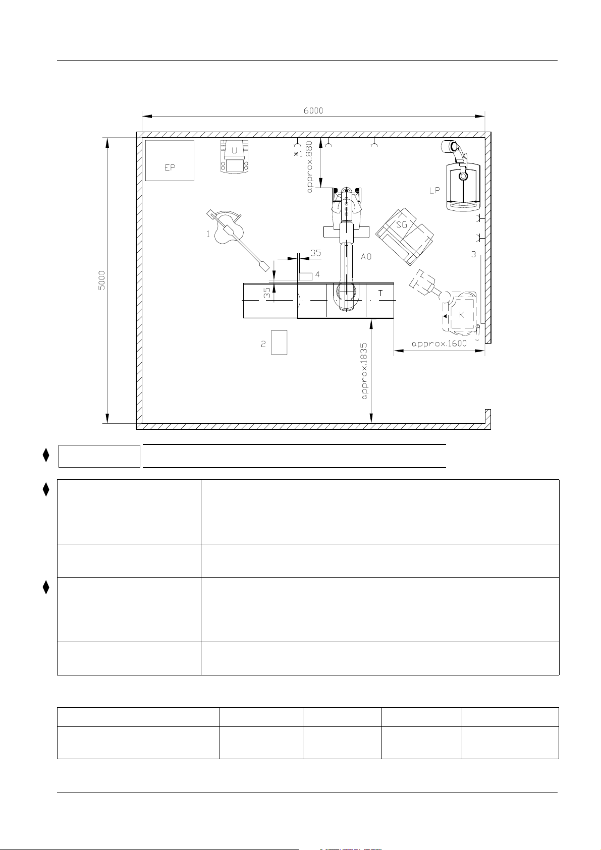
MODULARIS Uro Plus Room Planning Recommendation, "Total Config." 2
Head end
NOTE
MODULARIS Uro Plus
"Total Configuration"
Can be ordered from
SIEMENS
Customer Power outlets (*1 ARCADIS Orbic power outlet),
from the
RICHARD WOLF Co.
Room Size
The floor must be level in the area marked AO and T.
AO = ARCADIS Orbic, SG = Monitor cart, T = MODULARIS Uro
(patient table), LP = LITHOSTAR MODULARIS, U = SONOLINE G20
(option),
Patients monitor (option), location on LITHOSTAR MODULARIS
K = KION anesthesia unit, 1 = OP lamp
4 = Stationary water installation (at customer’s request)
2 = Height-adjustable container for rinse solutions
With anesthesia unit: 3 = Power supply rail (for gas connection, observe
country-specific connectors)
EP = MODULARIS MUT (MUT = MOBIL UNIT TOWER)
without support arm (with support arm, see Page 2-11)
1 : 50
Area Length Width Height
Technical minimum
examination room size
Siemens AG SPL1-130.891.03 Page 1 of 12 MODULARIS Uro Plus
Medical Solutions Rev. 02 07.05 CS SD 21
30 m
2
6.0 m 5.0 m min. 2.4 m
Page 12

2 - 2 Room Planning
MODULARIS "Litho Configuration" Room Planning Recommendation 2
Head end
NOTE
MODULARIS
"Litho Configuration"
Can be ordered from
SIEMENS
Customer Power outlets (*1 ARCADIS Orbic power outlet),
The floor must be level in the area marked AO and T.
AO = ARCADIS Orbic, SG = Monitor carts, T = MODULARIS Uro
(patient table), LP = LITHOSTAR MODULARIS, U = SONOLINE G20
(option)
Patients monitor for ECG triggering (option), location on
LITHOSTAR MODULARIS
K = KION anesthesia unit, 1 = OP lamp
2 = Height-adjustable container rinse solutions
With anesthesia unit: 3 = Power supply rail (for gas connection, observe
country-specific connectors)
1 : 50
Room Size
Area Length Width Height
Technical minimum
examination room size
MODULARIS Uro Plus SPL1-130.891.03 Page 2 of 12 Siemens AG
Rev. 02 07.05 CS SD 21 Medical Solutions
20 m
2
4.8 m 4.1 m min. 2.4 m
Page 13

Room Planning 2 - 3
MODULARIS "UltraLith Configuration" Room Planning Recommendation 2
Head end
NOTE
NOTE
MODULARIS
"UltraLith Configuration"
Can be ordered from
SIEMENS
Customer 2 = Height-adjustable container rinse solutions
The floor must be level in the area marked T.
Room planning recommendation optional with ARCADIS Orbic, see Page 2-2
T = MODULARIS Uro (patient table), LP = LITHOSTAR MODULARIS,
U = SONOLINE G20
Patients monitor for ECG triggering (option), location on LITHOSTAR
MODULARIS
K = KION anesthesia unit
With anesthesia unit: 3 = Power supply rail (for gas connection, observe
country-specific connectors)
1 : 50
Room Size
Area Length Width Height
Technical minimum
examination room size
Siemens AG SPL1-130.891.03 Page 3 of 12 MODULARIS Uro Plus
Medical Solutions Rev. 02 07.05 CS SD 21
14.8 m
2
4.1 m 3.6 m min. 2.4 m
Page 14

2 - 4 Room Planning
MODULARIS "Endo Configuration" Room Planning Recommendation 2
Head end
NOTE
MODULARIS
"Endo Configuration"
Can be ordered from
SIEMENS
Customer Power outlets (*1 ARCADIS Orbic power outlet),
from the
RICHARD WOLF Co.
The floor must be level in the area marked T.
AO = ARCADIS Orbic, SG = Monitor carts, T = MODULARIS Uro
(patient table), U = SONOLINE G20 (option)
Patients monitor (option), location on LITHOSTAR MODULARIS
K = KION anesthesia unit, 1 = OP lamp
4 = Stationary water installation (at customer’s request)
2 = Height-adjustable container for rinse solutions
3 = Power supply rail (for gas connection, observe country-specific
connectors)
EP = MODULARIS MUT (MUT = MOBIL UNIT TOWER)
without support arm (with support arm, see Page 2-11)
1 : 50
Room Size
Area Length Width Height
Technical minimum
examination room size
MODULARIS Uro Plus SPL1-130.891.03 Page 4 of 12 Siemens AG
Rev. 02 07.05 CS SD 21 Medical Solutions
20 m
2
4.8 m 4.1 m min. 2.4 m
Page 15

Room Planning 2 - 5
ARCADIS Orbic Dimensions 2
RBV 23
RBV 23
1 : 20
With Lithotripsy
Horizontal lift: 200 mm
Vertical lift: 400 mm fixed at 1070 mm (*1)
Angulation:
Orbital rotation: 190° (± 95°) ± 0°
Horizontal pivot: ± 10°± 0°
With the laser light localizer option,
the following must be observed:
Siemens AG SPL1-130.891.03 Page 5 of 12 MODULARIS Uro Plus
Medical Solutions Rev. 02 07.05 CS SD 21
The laser light localizer has two lasers in Class 2 (IEC 825).
The country-specific regulations that are applicable from this
must be observed.
± 190°± 20°
± 0 mm
Page 16

2 - 6 Room Planning
Monitor Cart Dimensions 2
*1
*1 Option: black/white display
MODULARIS Uro Plus SPL1-130.891.03 Page 6 of 12 Siemens AG
Rev. 02 07.05 CS SD 21 Medical Solutions
Page 17

Room Planning 2 - 7
SONOLINE G20 with Monitor 2
Patients monitor Dimensions2
The patient monitor is placed on the LITHOSTAR MODULARIS
(mount, Part No. 55 31 343), see the patient monitor drawing on the
LITHOSTAR MODULARIS.
The required cables from the LITHOSTAR MODULARIS to the patient monitor are included in the
items shipped with the LITHOSTAR MODULARIS.
Patients monitor on the
LITHOSTAR MODULARIS
Siemens AG SPL1-130.891.03 Page 7 of 12 MODULARIS Uro Plus
Medical Solutions Rev. 02 07.05 CS SD 21
Page 18

2 - 8 Room Planning
LITHOSTAR MODULARIS Dimensions 2
Park position
NOTE
MODULARIS Uro Plus SPL1-130.891.03 Page 8 of 12 Siemens AG
Rev. 02 07.05 CS SD 21 Medical Solutions
The illustrations on this page are not to scale!
Page 19

Room Planning 2 - 9
LITHOSTAR MODULARIS 2
with Ultrasound Localization
Removable
Support arm pivoted
The mount for Ultrasound Localization is transferred to the shock head.
Siemens AG SPL1-130.891.03 Page 9 of 12 MODULARIS Uro Plus
Medical Solutions Rev. 02 07.05 CS SD 21
Page 20

2 - 10 Room Planning
MODULARIS Uro Dimensions 2
1 : 25
*1 Table extension, foot section Depending on application, can be inserted on the left or right
*2 Table extension, head section Depending on application, can be inserted on the left or right
*3 Radio-transparent tabletop It can also be installed to the right of the middle section *4
(Update Kit 56 66 651 J 1048). This section should not be
pointing in the direction of the entrance door (optical safety).
*4 Middle section
MODULARIS Uro Plus SPL1-130.891.03 Page 10 of 12 Siemens AG
Rev. 02 07.05 CS SD 21 Medical Solutions
Page 21

Room Planning 2 - 11
MODULARIS MUT 2
1 : 25
Siemens AG SPL1-130.891.03 Page 11 of 12 MODULARIS Uro Plus
Medical Solutions Rev. 02 07.05 CS SD 21
Page 22

2 - 12 Room Planning
This page intentionally left blank.
MODULARIS Uro Plus SPL1-130.891.03 Page 12 of 12 Siemens AG
Rev. 02 07.05 CS SD 21 Medical Solutions
Page 23

Preparation for Installation 3
3 - 1
Recommendation for On-site Electro Installation (Application Group 1) 3
Power distributor per DIN VDE 0100-710: 1994-10 Application Group 1 or national
regulations
(Recommendation for MODULARIS Uro Plus,
Total)
Proposal for power distributor
Power supply
Cable cross section of N
and PE must be identical
to L1, L2 and L3
The listed fuse ratings apply for an operating voltage of 230 V 1 ~ / 400 V 3
∼
If there are fluctuating operating voltages, the fuse
ratings must be changed to conform to national regulations.
To external, conductive parts
Power consumers, fixed and mobile e.g. power outlet
FI - switch 63 A/I
nating and pulsing direct current faults (recommended:
Siemens FI 5SZ3 466 0KG05 All-current sensitive or
ABB No. F 804 - 63 /0,03. Order from ABB Stotz; contact Heidelberg Tel. 06221 701-00).
For other power line voltages, an appropriate Fi - switch
must be obtained locally.
System breaker
30 mA, UN = 400/415 V ∼ for alter-
∆N
* Install depending on system configuration
Emergency off button with locking mechanism
On-off button with pilot lamp
MODULARIS MUT
KION anesthesia unit
LITHOSTAR MODULARIS
Patients monitor
ARCADIS Orbic (CEE-power outlet 16 A)
MODULARIS Uro
SONOLINE G20
Siemens AG SPL1-130.891.03 Page 1 of 4 MODULARIS Uro Plus
Medical Solutions Rev. 02 07.05 CS SD 21
Page 24

3 - 2 Preparation for Installation
Recommendation for On-site Electro Installation (Application group 2) 3
Power distributor per DIN VDE 0100-710: 1994-10 Application Group 2 or national
regulations
(Recommendation for r MODULARIS Uro Plus, Total)
The listed fuse ratings apply for an operating voltage of 230 V 1 ~ / 400 V 3 ∼
With fluctuating operating voltages, the fuse ratings must be changed to conform to national regulations.
Proposal for
power distributor
SV Safety
power supply
Power supply
Cable cross section of N
and PE must be identical
to L1, L2 and L3
To external, conductive parts
Power consumers, fixed and mobile e.g. power outlet
FI - switch 63 A/I
nating and pulsing direct current faults (recommendation: Siemens FI 5SZ3 466 0KG05 All-current sensitive
or ABB No. F 804 - 63 /0,03. Order from ABB Stotz; contact Heidelberg Tel. 06221 701-00).
For other power line voltages, an appropriate Fi - switch
must be obtained locally.
System breaker
Voltage monitoring and toggling device
per DIN VDE 0107
Isolation transformer with overload monitor
Isolation monitor
Message combination
30 mA, UN = 400/415 V ∼ for alter-
∆N
* Install depending on system configuration
Emergency off button with locking mechanism
On-off button with pilot lamp
MODULARIS MUT
KION anesthesia unit
LITHOSTAR MODULARIS
PE - Pin socket
Patients monitor
ARCADIS Orbic (CEE-power outlet 16 A)
MODULARIS Uro
SONOLINE G20
MODULARIS Uro Plus SPL1-130.891.03 Page 2 of 4 Siemens AG
Rev. 02 07.05 CS SD 21 Medical Solutions
Page 25

Preparation for Installation 3 - 3
Floor Properties 3
All modules with the exception of the patients monitor are mobile.
NOTE
The floor should be laid with a floor covering that has a hard surface which
allows the unit to be moved easily.
Siemens AG SPL1-130.891.03 Page 3 of 4 MODULARIS Uro Plus
Medical Solutions Rev. 02 07.05 CS SD 21
Page 26

3 - 4 Preparation for Installation
Stationary Water Installation (Recommendation) 3
Shut-off valve
Cover plate
Sealed with
sanitary silicon
Self-leveling
grout
When cutting out the
self-leveling grout and
concrete, observe static
specifications!
flush with floor
*1
Floor opening
On-site water connection: 1/2" external thread
*1
(flush with top surface of finished flooring)
Water installation
materials:
16 12 972 G 5354
(complete materials
from the on-site pipe)
1 : 2.5
On-site drain, 1" external thread
NOTE
Intrusion of foreign substances into the tap water supply must be prevented.
Please observe the legal regulations applicable in the countries, as well as the
local regulations.
MODULARIS Uro Plus SPL1-130.891.03 Page 4 of 4 Siemens AG
Rev. 02 07.05 CS SD 21 Medical Solutions
Page 27

System Connections 4
4 - 1
Cable Connections 4
Module Power cable
length
• LITHOSTAR
MODULARIS
• MODULARIS Uro
(patient table)
approx.
6 m
approx.
6 m
• SONOLINE G20 approx.
3.5 m
• Monitor carts
(ARCADIS Orbic)
z. Monitor carts
- ARCADIS Orbic
approx.
6 m
approx.
6 m
• KION anesthesia unit approx.
6 m
• Patients monitor ECG unit approx.
3 m
Connector
115/230 V:
connector type matched to CEE 7/VII grounded connector
115/230 V:
connector type matched to CEE 7/VII grounded connector
115 V: Type SJT with hospital-approved 3-pin male
connector
230 V: type match to CEE 7/VII grounded connector
115 V: hospital-approved, 15 A
230 V: CEE ME 320 P6 (16 A)
No power connector
115 V: Type SJT with hospital-approved 3-pin male
connector
230 V: type with CEE 7/VII grounded connector
115 V: Type SJT with hospital-approved 3-pin male
connector
230 V: type matched to CEE 7/VII grounded connector
• MODULARIS MUT approx.
5 m
NOTE
Because there are many different country-specific power connectors, it is
possible that the individual modules will have to be replaced.
Power connectors must be obtained locally.
For USA and Canada, the hospital-grade connector must be used.
115 V: Type SJT with hospital-approved 3-pin male
connector
230 V: type matched to CEE 7/VII grounded connector
Siemens AG SPL1-130.891.03 Page 1 of 2 MODULARIS Uro Plus
Medical Solutions Rev. 02 07.05 CS SD 21
Page 28

4 - 2 System Connections
This page intentionally left blank.
MODULARIS Uro Plus SPL1-130.891.03 Page 2 of 2 Siemens AG
Rev. 02 07.05 CS SD 21 Medical Solutions
Page 29

Technical Data 5
5 - 1
Electrical Data 5
* ARCADIS Orbic
MODULARIS Uro
(patient table)
LITHOSTAR
MODULARIS
SONOLINE G20
KION anesthesia
unit
MODULARIS MUT
(RICHARD WOLF
Co.)
Power line connection internal fusing Power line
internal resis-
tance
100/110/120/127/200/
230/240 V
50/60
100 - 230 V ± 10%
50/60
100/120/200/230 V
50/60
115/230 V
50/60
100 - 240 V
50/60
100 - 127/230 V
50/60
± 10%
± 1 Hz
± 1 Hz
± 1 Hz
± 10%
± 1 Hz
± 10%
± 1 Hz
± 1 Hz
± 10%
± 10%
15 A slow-blow above
200 V
20 A slow-blow
up to 127 V
10 A n.a.
16 A n.a.
3 A n.a.
6.3 A n.a.
9 A slow-blow
up to 127 V
16 A slow-blow above
200 V
≤ 0.3 Ohm
(100/120/127 V)
≤ 0.8 Ohm
(200/230/240 V)
n.a.
Power
consump-
tion
Short-term:
approx.
2.90 KVA
Long-term:
approx.
1.65 KVA
approx.
0.4 KVA
approx.
1.5 KVA
approx.
0.350 KVA
approx.
0.5 KVA
approx.
2.0 KVA
Weights and Heat Dissipation 5
Weight (kg) Heat dissipation (W)
* ARCADIS Orbic with 23 I.I. approx 350 approx. 500
Monitor cart approx. 180 approx. 150
MODULARIS Uro
(patient table)
LITHOSTAR MODULARIS approx. 200 approx. 700
SONOLINE G20 approx. 60 approx. 450
KION anesthesia unit approx. 180 approx. 400
MODULARIS MUT
(RICHARD WOLF Co.)
* Observe the PG: ARCADIS Orbic, SPR2-320.891.01...
approx. 210 with max. config.
approx. 280 approx. 100
approx. 500
with max. config. 1000
Siemens AG SPL1-130.891.03 Page 1 of 4 MODULARIS Uro Plus
Medical Solutions Rev. 02 07.05 CS SD 21
Page 30

5 - 2 Technical Data
Environmental Conditions 5
Operation Transport/Storage
ARCADIS Orbic
Monitor cart
LITHOSTAR
MODULARIS
MODULARIS Uro
SONOLINE G20
KION
anesthesia unit
Admissible ambient
temperature
Admissible rel. humidity 30%... 75% 30% ... 75%
Atmospheric pressure 700 hPa - 1060 hPa 700 hPa - 1060 hPa
Admissible ambient
temperature
Admissible rel. humidity 30% ... 75% 30% ... 75%
Atmospheric pressure 700 hPa - 1060 hPa 700 hPa - 1060 hPa
Admissible ambient
temperature
Admissible rel. humidity 30% ... 75% 10% ... 100%
Atmospheric pressure 700 hPa - 1060 hPa 500 hPa - 1060 hPa
Admissible ambient
temperature
Admissible rel. humidity 20% ... 85% 20% ... 85%
Atmospheric pressure 700 hPa - 1060 hPa 700 hPa - 1060 hPa
Admissible ambient
temperature
Admissible rel. humidity 30% ... 75% 30% ... 75%
° C ... + 37° C- 20° C ... + 37° C
+ 10
° C ... + 40° C- 20° C ... + 60° C
+ 10
° C ... + 40° C- 40° C ... + 70° C
+ 10
° C ... + 40° C- 20° C ... + 60° C
+ 10
° C ... + 35° C- 10° C ... + 60° C
+ 15
MODULARIS MUT
(RICHARD WOLF Co.)
Atmospheric pressure 700 hPa - 1060 hPa 700 hPa - 1060 hPa
Admissible ambient
temperature
Admissible rel. humidity 30% ... 75% 10% ... 90%
Atmospheric pressure 700 hPa - 1060 hPa 500 hPa - 1060 hPa
° C ... + 40° C- 20° C ... + 60° C
+ 10
MODULARIS Uro Plus SPL1-130.891.03 Page 2 of 4 Siemens AG
Rev. 02 07.05 CS SD 21 Medical Solutions
Page 31

Technical Data 5 - 3
Paint Colors 5
Primary color Medical White C610
Base Medium Basic A701
Grips Medical Blue C750
Additional Data 5
ARCADIS Orbic see PG SPR2-320.891.01...
Noise Development 5
Test equipment
Larson Davis:
Realtime Time Analyser 2900
Precision Microphone 2541
Mircrophne Preamplifier 900B
Precision Sound Calibrator CA 250
For the user
Noise generation [db (A)]
⎯
1.5 meters from the noise source at 2 Hz final frequency
Behind the radiation safety wall
Energy level 4 74 68
Energy level 8 90 72
With 8 patients
(3000 shock waves / patient results in a load of)
Energy level 4 76 [db (A)]
Energy level 8 85 [db (A)]
For the patient
Noise generation [db (A)]
⎯
1.5 meters from the noise source at 2 Hz final frequency
Energy level 4 77
Energy level 8 82
Siemens AG SPL1-130.891.03 Page 3 of 4 MODULARIS Uro Plus
Medical Solutions Rev. 02 07.05 CS SD 21
Page 32

5 - 4 Technical Data
Packaging 5
Packaging size L x W x H / mm: 2450 x 990 x 2100
* ARCADIS Orbic
Weight with 23 RBV approx. 650 kg
with packaging (overseas packing)
* Monitor cart
LITHOSTAR MODULARIS
MODULARIS Uro
(patient table)
SONOLINE G20
KION anesthesia unit
MODULARIS MUT
(RICHARD WOLF Co.)
Packaging size L x W x H / mm: 980 x 910 x 1910
Weight approx. 195 kg without packaging
Packaging size L x W x H / mm: 1400 x 800 x 2200
Weight approx. 220 kg with packaging
Packaging size L x W x H / mm: 1480 x 940 x 1340
Weight approx. 300 kg with packaging
Packaging size L x W x H / mm: 960 x 600 x 1450
Weight approx. 83 kg with packaging
Packaging size L x W x H / mm: 750 x 590 x 1500
Weight approx. 210 kg with packaging
Packaging size L x W x H / mm: 900 x 750 x 1600
Weight approx. 230 kg without packaging
Gas Supply for KION Anesthesia Unit 5
Gas supply source O
, air, N2O
2
Gas pressure min. 2.8 / max. 6 bar (O
NOTE
* Observe the PG: ARCADIS Orbic, SPR2-320.891.01...
Observe country-specific connectors for the gas connection.
, air, N2O)
2
MODULARIS Uro Plus SPL1-130.891.03 Page 4 of 4 Siemens AG
Rev. 02 07.05 CS SD 21 Medical Solutions
Page 33

Transportation Specifications 6
6 - 1
Transport Pathways 6
without packaging
min. 850 mm
approx. 1800 mm
min.1900 mm
door opening
hallway width
door height
Elevator Requirements 6
min. 850 mm
without packaging
Lift capacity min. 375 kg
NOTE
LITHOSTAR MODULARIS:
Transport and storage with no water filled in.
Transport of LITHOSTAR MODULARIS without Ultrasound mount.
min. 1900 mm
min. 2160 mm
door opening
door height
elevator compartment length
Transmobile Insert 6
NOTE
Siemens AG SPL1-130.891.03 Page 1 of 2 MODULARIS Uro Plus
Medical Solutions Rev. 02 07.05 CS SD 21
LITHOSTAR MODULARIS
Transport Temperature + 10° C.....+ 37° C
Page 34

6 - 2 Transportation Specifications
This page intentionally left blank.
MODULARIS Uro Plus SPL1-130.891.03 Page 2 of 2 Siemens AG
Rev. 02 07.05 CS SD 21 Medical Solutions
Page 35

Changes to Previous Version 7
Chapter Page Change
0 - 7 Rev. status of the entire document raised from 01 to 02.
1 1-4 SIREMOBIL Iso C replaced by ARCADIS Orbic.
7 - 1
11-5
2 2-1 to 2-4 SIREMOBIL Iso C replaced by ARCADIS Orbic.
2 2-5 New illustration inserted.
2 2-6 Dimensions of the monitor cart, new illustration inserted.
3 3-1 and 3-2 SIREMOBIL Iso C replaced by ARCADIS Orbic.
4 4-1 SIREMOBIL Iso C replaced by ARCADIS Orbic.
5 5-1 to 5-4 Technical data updated.
7 7-1 Changes to Previous Version updated.
SIREMOBIL Iso C replaced by ARCADIS Orbic, text updated and
Note text added.
Siemens AG SPL1-130.891.03 Page 1 of 2 MODULARIS Uro Plus
Medical Solutions Rev. 02 07.05 CS SD 21
Page 36

7 - 2 Changes to Previous Version
This page intentionally left blank.
MODULARIS Uro Plus SPL1-130.891.03 Page 2 of 2 Siemens AG
Rev. 02 07.05 CS SD 21 Medical Solutions
 Loading...