

Page 1

Erlwein
MODULARIS Litho Vario
Installation and Start-up
System
SP
MODULARIS Litho Vario
01158059
Print No.:
Replaces: SPL1-130.814.02.06.02
SPL1-130.814.02.07.02
© Siemens AG
The reproduction, transmission or use
of this document or its contents is not
permitted without express written
authority. Offenders will be liable for
damages. All rights, including rights
created by patent grant or registration
of a utility model or design, are
reserved.
English
Doc. Gen. Date: 02.05
2003
Page 2

2 Revision / Disclaimer
1Revision / Disclaimer
Document revision level
The document corresponds to the version/revision level effective at the time of system
delivery. Revisions to hardcopy documentation are not automatically distributed.
Please contact your local Siemens office to order current revision levels.
Disclaimer
The installation and service of equipment described herein is to be performed by qualified
personnel who are employed by Siemens or one of its affiliates or who are otherwise
authorized by Siemens or one of its affiliates to provide such services.
Assemblers and other persons who are not employed by or otherwise directly affiliated
with or authorized by Siemens or one of its affiliates are directed to contact one of the
local offices of Siemens or one of its affiliates before attempting installation or service procedures.
MODULARIS Litho Vario SPL1-130.814.02.07.02 Siemens AG
02.05 CS PS 24
Page 2 of 88
Medical Solutions
Page 3

Table of Contents 3
1- 0Table of Contents
1 _______ General information______________________________________________ 5
Important start-up information . . . . . . . . . . . . . . . . . . . . . . . . . . . . . . . . . . . . . . . . . . . . . 5
Applicability and regulations for regional companies . . . . . . . . . . . . . . . . . . . . . . . . . 5
MODULARIS Vario overview . . . . . . . . . . . . . . . . . . . . . . . . . . . . . . . . . . . . . . . . . . . . . . 6
MODULARIS Vario . . . . . . . . . . . . . . . . . . . . . . . . . . . . . . . . . . . . . . . . . . . . . . . . . . . 6
Required technical documents . . . . . . . . . . . . . . . . . . . . . . . . . . . . . . . . . . . . . . . . . . . . . 7
Required tools and measurement devices . . . . . . . . . . . . . . . . . . . . . . . . . . . . . . . . . . . . 8
Required material . . . . . . . . . . . . . . . . . . . . . . . . . . . . . . . . . . . . . . . . . . . . . . . . . . . . 8
Protective measures. . . . . . . . . . . . . . . . . . . . . . . . . . . . . . . . . . . . . . . . . . . . . . . . . . . . . 9
2 _______ Installation ____________________________________________________ 10
Overview. . . . . . . . . . . . . . . . . . . . . . . . . . . . . . . . . . . . . . . . . . . . . . . . . . . . . . . . . . . . . 10
SIREMOBIL and monitor trolley . . . . . . . . . . . . . . . . . . . . . . . . . . . . . . . . . . . . . . . . 10
MODULARIS Uro Plus . . . . . . . . . . . . . . . . . . . . . . . . . . . . . . . . . . . . . . . . . . . . . . . 10
SONOLINE . . . . . . . . . . . . . . . . . . . . . . . . . . . . . . . . . . . . . . . . . . . . . . . . . . . . . . . . 10
Unpacking LITHOSTAR MODULARIS Vario . . . . . . . . . . . . . . . . . . . . . . . . . . . . . . 10
Docking unit . . . . . . . . . . . . . . . . . . . . . . . . . . . . . . . . . . . . . . . . . . . . . . . . . . . . . . . 12
Combination with ARCADIS Orbic/SIREMOBIL . . . . . . . . . . . . . . . . . . . . . . . . . . . . 18
Unit association - labeling . . . . . . . . . . . . . . . . . . . . . . . . . . . . . . . . . . . . . . . . . . . . . 19
C-arm unit isocenter cross . . . . . . . . . . . . . . . . . . . . . . . . . . . . . . . . . . . . . . . . . . . . 20
External isocenter cross manufacturer . . . . . . . . . . . . . . . . . . . . . . . . . . . . . . . . . . . 21
Radiation release option . . . . . . . . . . . . . . . . . . . . . . . . . . . . . . . . . . . . . . . . . . . . . . 22
MODULARIS Uro Table . . . . . . . . . . . . . . . . . . . . . . . . . . . . . . . . . . . . . . . . . . . . . . 22
ECG triggering option . . . . . . . . . . . . . . . . . . . . . . . . . . . . . . . . . . . . . . . . . . . . . . . . 25
3 _______ Start-up _______________________________________________________ 28
C-arm unit and monitor trolley . . . . . . . . . . . . . . . . . . . . . . . . . . . . . . . . . . . . . . . . . . . . 28
LITHOSTAR MODULARIS . . . . . . . . . . . . . . . . . . . . . . . . . . . . . . . . . . . . . . . . . . . . . . . 29
Checking the line voltage . . . . . . . . . . . . . . . . . . . . . . . . . . . . . . . . . . . . . . . . . . . . . 29
Installing the coupling pump . . . . . . . . . . . . . . . . . . . . . . . . . . . . . . . . . . . . . . . . . . . 30
Filling the cooling circuit . . . . . . . . . . . . . . . . . . . . . . . . . . . . . . . . . . . . . . . . . . . . . . 30
Filling the coupling circuit . . . . . . . . . . . . . . . . . . . . . . . . . . . . . . . . . . . . . . . . . . . . . 31
Checking the isocenter with X-ray . . . . . . . . . . . . . . . . . . . . . . . . . . . . . . . . . . . . . . 32
Triggering shock waves . . . . . . . . . . . . . . . . . . . . . . . . . . . . . . . . . . . . . . . . . . . . . . 34
Triggering shock waves with ECG (optional) . . . . . . . . . . . . . . . . . . . . . . . . . . . . . . 35
Pressure measurement. . . . . . . . . . . . . . . . . . . . . . . . . . . . . . . . . . . . . . . . . . . . . . . 35
MODULARIS Uro (table) . . . . . . . . . . . . . . . . . . . . . . . . . . . . . . . . . . . . . . . . . . . . . . . . 36
Ultrasound localization (if present) . . . . . . . . . . . . . . . . . . . . . . . . . . . . . . . . . . . . . . . . . 37
SONOLINE G20 . . . . . . . . . . . . . . . . . . . . . . . . . . . . . . . . . . . . . . . . . . . . . . . . . . . . 38
SONOLINE Adara. . . . . . . . . . . . . . . . . . . . . . . . . . . . . . . . . . . . . . . . . . . . . . . . . . . 38
SONOLINE Prima . . . . . . . . . . . . . . . . . . . . . . . . . . . . . . . . . . . . . . . . . . . . . . . . . . . 38
Probes. . . . . . . . . . . . . . . . . . . . . . . . . . . . . . . . . . . . . . . . . . . . . . . . . . . . . . . . . . . . 39
Selecting the MODULARIS cross on the SONOLINE G20 . . . . . . . . . . . . . . . . . . . . . . 41
Ultrasound localization . . . . . . . . . . . . . . . . . . . . . . . . . . . . . . . . . . . . . . . . . . . . . . . 41
Selecting the MODULARIS cross on the SONOLINE Adara . . . . . . . . . . . . . . . . . . . . . 42
Ultrasound localization . . . . . . . . . . . . . . . . . . . . . . . . . . . . . . . . . . . . . . . . . . . . . . . 42
Siemens AG SPL1-130.814.02.07.02 MODULARIS Litho Vario
Medical Solutions
02.05 CS PS 24
Page 3 of 88
Page 4

4 Table of Contents
Selecting the MODULARIS cross on the SONOLINE Prima . . . . . . . . . . . . . . . . . . . . . 43
. . . . . . . . . . . . . . . . . . . . . . . . . . . . . . . . . . . . . . . . . . . . . . . . . . . . . . . . . . . . . . . . . . 43
Ultrasound localization . . . . . . . . . . . . . . . . . . . . . . . . . . . . . . . . . . . . . . . . . . . . . . . 43
Adhesive labels for ultrasound units . . . . . . . . . . . . . . . . . . . . . . . . . . . . . . . . . . . . . . . . 45
MUT MODULARIS . . . . . . . . . . . . . . . . . . . . . . . . . . . . . . . . . . . . . . . . . . . . . . . . . . . . . 46
Final work steps . . . . . . . . . . . . . . . . . . . . . . . . . . . . . . . . . . . . . . . . . . . . . . . . . . . . . . . 47
4 _______ Ultrasound localization retrofit ____________________________________ 48
Cable mount on the support arm. . . . . . . . . . . . . . . . . . . . . . . . . . . . . . . . . . . . . . . . . . . 52
Cable holder on the cable . . . . . . . . . . . . . . . . . . . . . . . . . . . . . . . . . . . . . . . . . . . . . . . . 53
Ultrasound probes. . . . . . . . . . . . . . . . . . . . . . . . . . . . . . . . . . . . . . . . . . . . . . . . . . . . . . 54
Adhesive labels for ultrasound unit . . . . . . . . . . . . . . . . . . . . . . . . . . . . . . . . . . . . . . . . . 55
Adjustment and start-up . . . . . . . . . . . . . . . . . . . . . . . . . . . . . . . . . . . . . . . . . . . . . . . . . 56
LithoShare with several ultrasound units . . . . . . . . . . . . . . . . . . . . . . . . . . . . . . . . . . . . 57
SONOLINE G20 . . . . . . . . . . . . . . . . . . . . . . . . . . . . . . . . . . . . . . . . . . . . . . . . . . . . 57
SONOLINE Adara . . . . . . . . . . . . . . . . . . . . . . . . . . . . . . . . . . . . . . . . . . . . . . . . . . . 58
SONOLINE Prima . . . . . . . . . . . . . . . . . . . . . . . . . . . . . . . . . . . . . . . . . . . . . . . . . . . 59
5 _______ Isocenter with ultrasound ________________________________________ 60
Preparations . . . . . . . . . . . . . . . . . . . . . . . . . . . . . . . . . . . . . . . . . . . . . . . . . . . . . . . . . . 60
Checking the target on the SONOLINE G20 . . . . . . . . . . . . . . . . . . . . . . . . . . . . . . . 62
Checking image tilt . . . . . . . . . . . . . . . . . . . . . . . . . . . . . . . . . . . . . . . . . . . . . . . . . . 64
Checking the target on the Sonoline Adara. . . . . . . . . . . . . . . . . . . . . . . . . . . . . . . . 69
Checking image tilt . . . . . . . . . . . . . . . . . . . . . . . . . . . . . . . . . . . . . . . . . . . . . . . . . . 70
Checking the target on the Sonoline Prima. . . . . . . . . . . . . . . . . . . . . . . . . . . . . . . . 76
Checking image tilt . . . . . . . . . . . . . . . . . . . . . . . . . . . . . . . . . . . . . . . . . . . . . . . . . . 78
6 _______ Final work steps ________________________________________________ 84
Customer and country-specific settings . . . . . . . . . . . . . . . . . . . . . . . . . . . . . . . . . . . . . 84
Setting the system clock (if necessary) . . . . . . . . . . . . . . . . . . . . . . . . . . . . . . . . . . . 84
Setting the user language (if necessary). . . . . . . . . . . . . . . . . . . . . . . . . . . . . . . . . . 84
Backup and error memory. . . . . . . . . . . . . . . . . . . . . . . . . . . . . . . . . . . . . . . . . . . . . . . . 85
Remaining work . . . . . . . . . . . . . . . . . . . . . . . . . . . . . . . . . . . . . . . . . . . . . . . . . . . . . . . 86
7 _______ Changes to previous version _____________________________________ 87
MODULARIS Litho Vario SPL1-130.814.02.07.02 Siemens AG
02.05 CS PS 24
Page 4 of 88
Medical Solutions
Page 5

General information 5
1General information
2-
Important start-up information 0
The device was installed, programmed, and tested at the factory (see the test certificate
filed in the “technical documentation” system binder).
During start-up, you will only need to perform a few tests or measurements to ensure that
none of the settings have changed.
All measurement results from measurements labeled with p must be entered in the
test certificate listed in each instance.
NOTE
These measurement values as well as the values determined during start-up can be copied from the test certificate to the acceptance certificate.
Applicability and regulations for regional companies 0
Equivalent leakage current measurement
The equivalent leakage current must be measured where applicable under the requirements of DIN VDE 0751 Part 1.
Where DIN VDE 0751 does not apply, the regional companies should comply with the following regulations (refer to ARTD - 002.731.17, Safety-related regulations for installation
and maintenance).
The national regulations apply primarily for the regional companies.
In the event that there are no existing regulations, the following provisions should be
adhered to in the interest of the safety of customers, patients, employees and third parties
as well as the company.
Initial measured value
The equivalent leakage current measurement was performed at the factory and the value
measured was entered in test protocol 1. The measurement was made at the line voltage
and line frequency indicated in test protocol 1.
If the on-site line voltage or line frequency deviates from the information indicated upon
delivery, the values given are invalid. The values should be marked invalid (crossed out
with the comment “invalid values“ and this copy should be signed and dated).
The equivalent leakage current measurement must be repeated. According the DIN VDE
0751 Part 1, the resulting value may not exceed 1 mA.
The initial measured value must be documented.
Repeat measurements
When service or repair work is performed on the primary power supply circuit (e.g. repairs
to the power-on circuit), the equivalent leakage current test must be repeated. The values
measured in the subsequent test may not exceed the threshold value of 1 mA as specified
in VDE 0751, Part 1. In addition, they may not exceed the initial measured value by more
than 50%. If the value exceeds this threshold, the system must be repaired. The measured value must be documented.
Siemens AG SPL1-130.814.02.07.02 MODULARIS Litho Vario
Medical Solutions
02.05 CS PS 24
Page 5 of 88
Page 6

6 General information
MODULARIS Vario overview 0
MODULARIS Vario 0
Fig. 1: Vario
Pos. 1 Shock wave head C plus with 140 mm penetration depth with adapted isocenter phantom.
Pos. 2 Therapy arm incl. head
Pos. 3 Energy charger with fast high voltage switch
Pos. 4 Docking system with docking mandrel
900 mm
MODULARIS Litho Vario SPL1-130.814.02.07.02 Siemens AG
02.05 CS PS 24
Page 6 of 88
Medical Solutions
Page 7

General information 7
Required technical documents 0
• Start-up, release for operation SPL1-130.815.01..
• * Dimension certificate from the PG SPL1-130.891.01..
• MODULARIS Vario service instructions SPL1-130.840.01..
• **C-arm unit installation instructions n.a.
• **Monitor trolley installation instructions n.a.
• **C-arm unit start-up instructions n.a.
• **LITHOSTAR MODULARIS Vario adaptation SPR2-130.814.05..
• MODULARIS Uro Plus operating instructions SPL1-130.620.01..
• MODULARIS Vario operating instructions SPL1-130.620.05..
• C-arm unit operating instructions n.a.
• Service instructions for shock wave pressure and po-
sition control
* Only in combination with a non-Siemens C-arm unit.
**Only in combination with Siemens C-arm units.
SPL2-120.074.01
Siemens AG SPL1-130.814.02.07.02 MODULARIS Litho Vario
Medical Solutions
02.05 CS PS 24
Page 7 of 88
Page 8

8 General information
Required tools and measurement devices 0
• Standard installation tool kit
• Service PC, see intranet, service laptop for CSEs
• PC connection cable, 5m 99 00 440 RE999
• Internal line resistance meter 84 28.104 RE999
• ESD equipment
• Protective conductor tester 44 15 899 RV090
• DVM, e.g.. Fluke 187 99 94 831
• Pressure test device 30 95 408 J1008
• Adapter for C-head 98 17 347 J1008
• Bender safety tester 97 06 979 Y0526
• Spray can or varnish applicator of the color white grained
MED surface no. 4146 similar to RAL grayish white 9002.
99 00 705 RE999
Required material 0
• Approx. 5 liters of sterile water
MODULARIS Litho Vario SPL1-130.814.02.07.02 Siemens AG
02.05 CS PS 24
Page 8 of 88
Medical Solutions
Page 9

General information 9
Protective measures 0
• Adhere to the protective measures described in register 1 of the system binder.
• When performing the work steps, the product-specific safety information contained in
the document as well as the general safety information in ARTD, Part 2 must be observed.
• Observe ESD guidelines!
WARNING
Dangerous X-ray radiation and/or dangerous electrical voltage
during test and adjustment operations!
Disregarding safety precautions can result in death or serious
bodily injury.
¹ The following points must be observed:
¹ Disconnect the power cable when working on the sys-
tem.
¹ Ensure compliance with the general safety requirements
when working with the system under power.
¹ Switch off the power prior to replacing modules or
boards.
¹ After all work has been completed and all covers have
been installed, perform the protective conductor test
according to ARTD-002.731.17...
¹ The protective conductor resistance must not exceed 0.2
Ohms.
¹ When performing service work on the power-on module,
(replacing the power-on module or replacing the power
cable), the equivalent leakage current must be measured
and recorded.
¹ Checks and settings that need to be performed under
X-ray radiation are identified by the radiation warning
symbolx . When performing adjustments labeled as
shown here, appropriate radiation protection measures
must be taken (see ARTD, Part 2).
Siemens AG SPL1-130.814.02.07.02 MODULARIS Litho Vario
Medical Solutions
02.05 CS PS 24
Page 9 of 88
Page 10

10 Installation
2Installation
3-
Overview 0
SIREMOBIL and monitor trolley 0
Refer to the valid installation instructions of the two units when installing the SIREMOBIL
and the monitor trolley:
MODULARIS Uro Plus 0
Also refer to the document SPL1-130.033.02.. when installing the MODULARIS Uro (table
with Litho opening).
SONOLINE 0
SONOLINE does not require any special installation instructions
Simply unpack the unit according to the "Unpacking procedure" attached to the outside
and attach the accessories including the monitor.
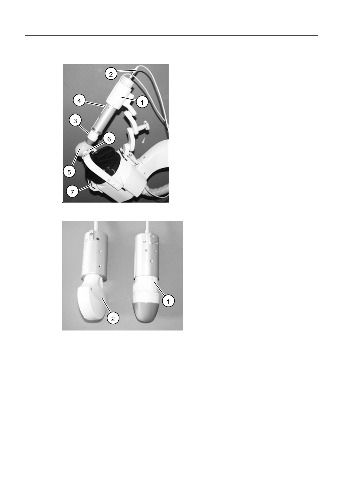
Unpacking LITHOSTAR MODULARIS Vario 0
Fig. 2: Head, complete
NOTICE
Do not pull on the focus phantom (bracket (4/Fig. 2 / p. 10)), risk of
damage!
¹ Do not use the phantom as a handle.
• Remove the packaging above the unit.
MODULARIS Litho Vario SPL1-130.814.02.07.02 Siemens AG
02.05 CS PS 24
Page 10 of 88
Medical Solutions
Page 11

Installation 11
Fig. 3: Ramp 01
Fig. 4: Ramp 2
• Remove the transport safety screw (1/Fig.3/p.11) used to secure the unit and the
ramp (2/Fig.3/p.11).
• Remove all transport safety brackets (3/Fig.3/p.11).
• Slide the ramp (5/Fig.4/p.11) out of the transport pallet from the back to the front and
position it appropriately.
• Move the unit off the transport pallet and down the ramp.
• Appropriately dispose of the packaging according to the country-specific regulations.
• Adapt the power cord to the country-specific requirements, if required. If necessary,
materials will have to be purchased locally. Use a hospital grade plug for the USA and
for Canada.
• Secure the operating panel bracket with the screws.
• Connect the operating panel.
Siemens AG SPL1-130.814.02.07.02 MODULARIS Litho Vario
Medical Solutions
02.05 CS PS 24
Page 11 of 88
Page 12

12 Installation
• Place the control panel in the mount.
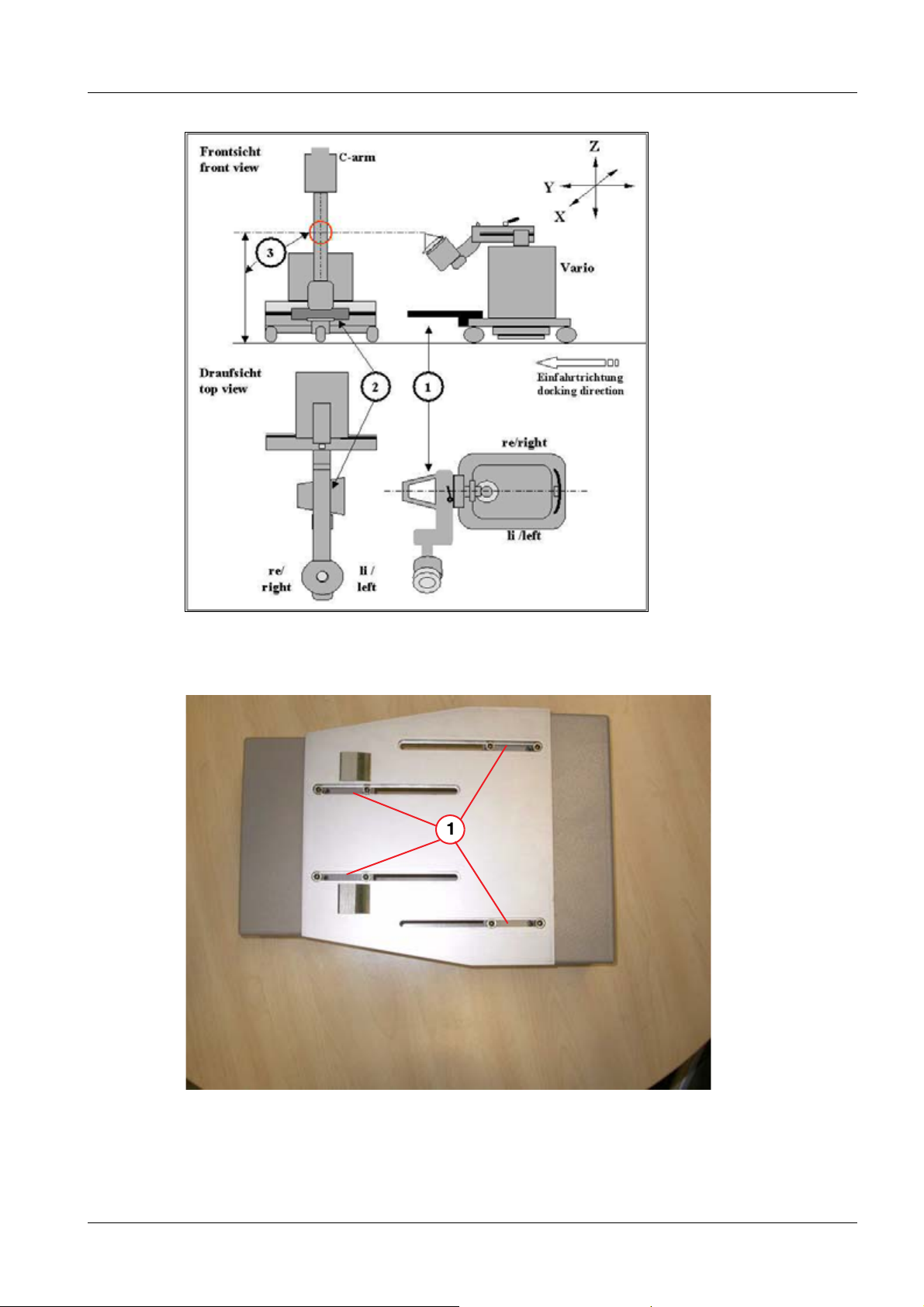
Docking unit 0
NOTE
NOTE
The docking mandrel is pre-installed on the Vario centrally in relation to the longitudinal
axis (1/Fig.5/p.13) and can be adjusted by 30 mm in height (200 to 230 mm above the
floor). The height is determined depending on the installation of the docking bridge. The
docking bridge is installed on the front C-arm unit extension (2/Fig.5/p.13) and
(Fig. 16 / p. 18).
This chapter first describes mechanical coupling for Vario in combination with SIREMOBIL Compact. The differences with regard to
the combination with SIREMOBIL ISO-C with a separate bridge are
subsequently illustrated.
The procedure is the same for all C-arm units. Mechanical installation of the bridge on the front extension of the C-arm unit must always be adapted. Technical clarification must be known and in
conformance with PG (SPL1-130.890.01...).
For the sake of clarity regarding technical work on all components,
the coordinates are determined in this document in Fig.
(Fig.5/p.13) (Vario with shock wave focus, C-arm unit with iso-
center, patient table). Side designations left and right are always
used for Vario and C-arm unit from the viewpoint of the operator in
a forward direction.
NOTE
The following diagrams are not shown to scale and apply for Vario
with Siremobil Compact and Compact L. Pre-clarification by the local project management is required for any other C-arm unit. The
procedure is then the same.
MODULARIS Litho Vario SPL1-130.814.02.07.02 Siemens AG
02.05 CS PS 24
Page 12 of 88
Medical Solutions
Page 13
Installation 13
Fig. 5: Docking unit
Fig. 6: Docking securing_4
Siemens AG SPL1-130.814.02.07.02 MODULARIS Litho Vario
Medical Solutions
02.05 CS PS 24
Page 13 of 88
Page 14

14 Installation
Fig. 7: Docking securing_2
Fig. 8: Docking securing_3
• Prepare the Vario to the left of the C-arm on a level floor (fix C-arm)
• Set the C-arm vertically to approx. 1070 mm in the center ((3/Fig.5/p.13)_ Z direction)
• Remove the top part of the docking bridge.
• Unscrew the docking bridge (1/Fig.6/p.13) or detailed view (1/Fig.7/p.14) and pull
the docking bridge apart so that the complete adjustment range is available.
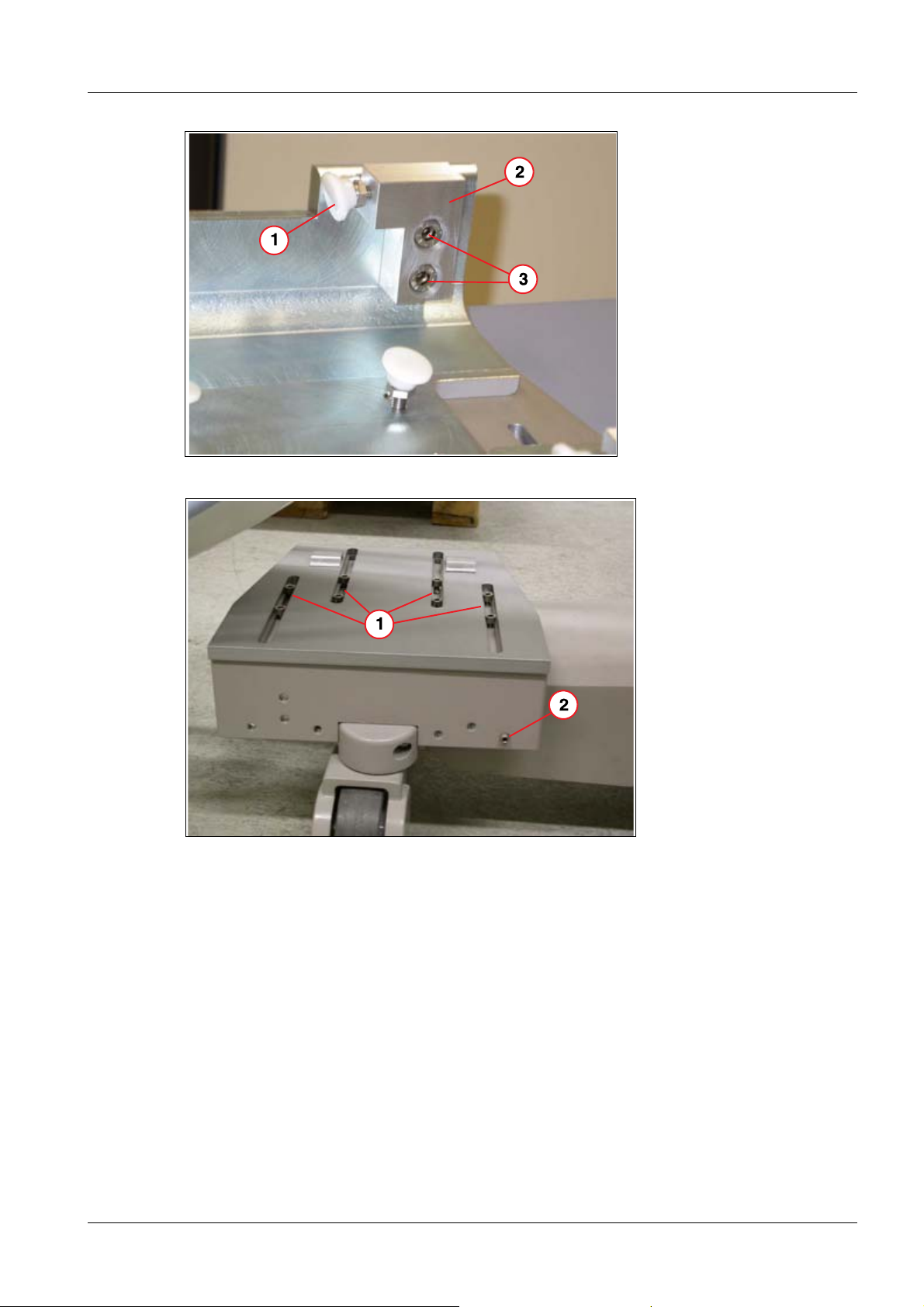
• Place the bottom part of the docking bridge on the C-arm extension, min. 140 mm in the
X direction (1/Fig.9/p.15) and approximately centered.
• The docking bridge can be positioned horizontally via Allen screws (2/Fig.7/p.14). If
the adjustment range is insufficient, the preinstalled Allen screws (1/2/3/Fig. 8 / p. 14)
can be replaced with the included longer screws.
MODULARIS Litho Vario SPL1-130.814.02.07.02 Siemens AG
02.05 CS PS 24
Page 14 of 88
Medical Solutions
Page 15
Installation 15
• Tighten the eight fastening screws (1/Fig.6/p.13) and (Fig.7/p.14).
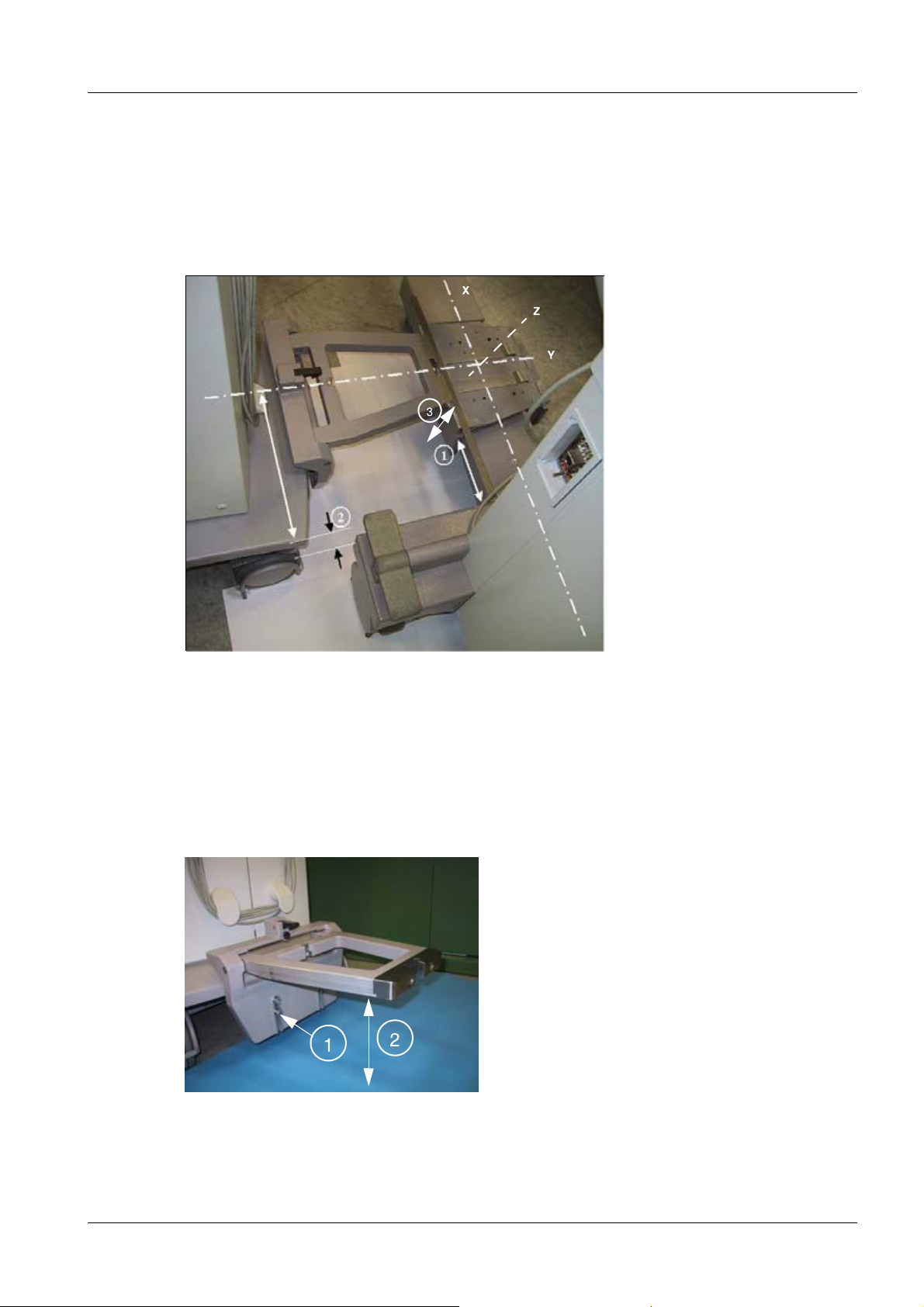
• Set the Vario docking mandrel in the horizontal position (1/Fig.5/p.13).
• Set the Vario arm to be horizontal (gel or therapy position)
• When the Vario moves in, the mandrel must move over the lower part of the sleeve -
check heights from the floor (2/Fig. 10 / p. 15). Adjusting screws for adjusting the height
of the mandrel, see (1/Fig. 10 / p. 15). Use a level for this adjustment.
Fig. 9: Docking unit 2
• Move Vario in with a distance of at least 90 mm (2/Fig.9/p.15).
• Align the lower part of the docking bridge to the mandrel in X direction (1/Fig.9/p.15).
• Secure the bottom part with the Allen screw (1/Fig. 11 / p. 16).
• Position the top part of the docking bridge and secure it (1/Fig. 12 / p. 16).
• Test the inward movement and locking of the Vario. The latch must lock securely. Cor-
rection is performed using the black Allen screw in the latch (2/Fig. 12 / p. 16).
Fig. 10: View 1
Siemens AG SPL1-130.814.02.07.02 MODULARIS Litho Vario
Medical Solutions
02.05 CS PS 24
Page 15 of 88
Page 16

16 Installation
Fig. 11: Lower part_
Fig. 12: Upper part
MODULARIS Litho Vario SPL1-130.814.02.07.02 Siemens AG
02.05 CS PS 24
Page 16 of 88
Medical Solutions
Page 17
Installation 17
Fig. 13: Block
Fig. 14: Block_
Siemens AG SPL1-130.814.02.07.02 MODULARIS Litho Vario
Medical Solutions
02.05 CS PS 24
Page 17 of 88
Page 18

18 Installation
Fig. 15: Block_mounted
Fig. 16: View 3
.
Combination with ARCADIS Orbic/SIREMOBIL 0
The bridge is to be modified for ARCADIS Orbic and SIREMOBIL ISO-C according to
(Fig. 13 / p. 17).
• Remove both clamping screws (3/Fig.8/p.14).
• Screw the clamping screws from the enclosed material into the fastening block (1 und
2/Fig. 13 / p. 17).
• Attach these blocks to the bridge with 2 screws (3/Fig. 13 / p. 17).
• Position the bridge according to (Fig. 14 / p. 17).
• Horizontally position the bridge via the clamping screw (1/Fig. 14 / p. 17) (or see
(2/Fig.7/p.14) for more detail).
• Secure the bridge with the clamping screw (2/Fig. 14 / p. 17) and (1/Fig. 15 / p. 18).
MODULARIS Litho Vario SPL1-130.814.02.07.02 Siemens AG
02.05 CS PS 24
Page 18 of 88
Medical Solutions
Page 19

Installation 19
• Position the top part of the docking bridge and secure it (1/Fig. 12 / p. 16).
• Test the inward movement and locking of the Vario. The latch must lock securely. Cor-
rection is performed using the black Allen screw in the latch (2/Fig. 12 / p. 16).
Unit association - labeling 0
Label the supplied sticker with a permanent marker as shown in Figure: (Fig. 17 / p. 19).
All combinable C-arm units must be listed on the Vario. The combinable Vario must be
labeled on the C-arm unit. Attach label 1 (Figure (1/Fig. 17 / p. 19)) to the Vario (Figure:
(1/Fig. 18 / p. 20)). Attach label 2 (Figure: (Fig. 17 / p. 19)) to the C-arm unit in one of the
indicated areas (Figure: (2/Fig. 18 / p. 20)) so that no manufacturer information is covered. Cover both labels with a transparent film.
Fig. 17: Label 1
Siemens AG SPL1-130.814.02.07.02 MODULARIS Litho Vario
Medical Solutions
02.05 CS PS 24
Page 19 of 88
Page 20

20 Installation
Fig. 18: Label 2
C-arm unit isocenter cross 0
Fig. 19: Cross
Fig. 20: I.I. 1
MODULARIS Litho Vario SPL1-130.814.02.07.02 Siemens AG
02.05 CS PS 24
Page 20 of 88
Medical Solutions
Page 21

Installation 21
Fig. 21: I.I. 2
Fig. 22: 3 cm I.I.
Attachment of the isocenter cross to the SIREMOBIL Compact and Compact L
• Remove the front screw on the I.I. and replace it with the M4 x 16 screw included in the
shipment (1/Fig. 22 / p. 21).
• The crosshairs must be position in the center of the mounting ring. Check this with a
tape measure and correct it if necessary.
• Snap the isocenter cross onto the I.I.
• Attach the arrows (Figure: (Fig. 20 / p. 20)) (indicating the centering stud).
• Place the supplied "serial number" labels on the isocenter cross (1/Fig. 22 / p. 21) and
the I.I. (2/Fig. 22 / p. 21).
External isocenter cross manufacturer 0
Depending on the I.I. diameter, select one of the three delivered crosshairs and attach the
corresponding retaining brackets.
• Install the movable bracket (3/Fig. 22 / p. 21) in the crosshair extension.
• Install the two fixed brackets accordingly (4/Fig. 22 / p. 21).
Siemens AG SPL1-130.814.02.07.02 MODULARIS Litho Vario
Medical Solutions
02.05 CS PS 24
Page 21 of 88
Page 22

22 Installation
• To allow for later adjustment, tighten the adjusting screw (5/Fig. 22 / p. 21) only loose-
ly. Use the center threaded hole first.
• Mount the grid and position it approximately in the middle.
• Attach the C-arm unit and the Litho module.
• Swing up the adjustment phantom on the shock wave head.
• Center the grid with the adjustment phantom under fluoroscopy by moving the retaining
brackets.
• Install the second screw in the retaining brackets and check again that the grid is cen-
tered.
• Adhere the arrows (6/Fig. 22 / p. 21) to the I.I.
Radiation release option 0
NOTE
This option is performed according to the instructions SPR2-130.814.05... "Installation
Instructions for LITHOSTAR Modularis Vario". A paper version of this document is part of
conversion kit number 71 40 952.
The radiation release option of the Lithostar operating panel is released only for Siremobil Compact and Compact L.
MODULARIS Uro Table 0
Installing the positioning yoke
• The positioning yoke is packed separately in the shipment (part no. 81 25 333).
• Attach the yoke to the table with the two screws as shown in ((1/Fig. 23 / p. 23)).
• The positioning yoke must be adjusted so that its height corresponds to that of the dock-
ing bridge ((1/Fig. 24 / p. 23)). Adjustment can be performed by turning the two rubber
stoppers ((2/Fig. 24 / p. 23)).
• The rubber stoppers must be secured by the screw ((1/Fig. 25 / p. 24)).
• No mechanical connection is created when operating the system for therapeutic pur-
poses. The C-arm is simply docked in the yoke.
• The yoke must be collapsed to the table base and rest completely on it when in the ta-
ble park position.
MODULARIS Litho Vario SPL1-130.814.02.07.02 Siemens AG
02.05 CS PS 24
Page 22 of 88
Medical Solutions
Page 23

Installation 23
Fig. 23: Positioning_yoke_1
Fig. 24: Positioning_yoke_2
Siemens AG SPL1-130.814.02.07.02 MODULARIS Litho Vario
Medical Solutions
02.05 CS PS 24
Page 23 of 88
Page 24

24 Installation
Fig. 25: Securing screw
Fig. 26: Positioning yoke
MODULARIS Litho Vario SPL1-130.814.02.07.02 Siemens AG
02.05 CS PS 24
Page 24 of 88
Medical Solutions
Page 25

Installation 25
ECG triggering option 0
Mounting the docking station
• Unscrew the rectangular plate (Fig. 27 / p. 26) from the docking station of the ECG
monitor. It is no longer required.
• Screw the docking station bracket from the conversion kit onto the round plate so that
the longitudinal grooves are visible from below (Fig. 28 / p. 26).
• Remove the round cap from the column of the system trolley. It is no longer required.
• Remove the cover from the system trolley.
• Disconnect the cables from the mount (7/Fig. 30 / p. 27).
• Plug the inlet connector for a non-heating apparatus (power cable) into the connector
strip (6/Fig. 30 / p. 27).
• Push the trigger cable from the D3.X70 board (beside the service switch) starting with
the jack plug, from beneath, through the column and lead it out, parallel to the wires, together with the power cable.
• Plug the inlet connector for a non-heating apparatus into the power supply unit of the
ECG monitor.
• Attach the power supply unit of the ECG monitor in the system cart to the support
(8/Fig. 30 / p. 27) via cable clamps.
• Push the 24 V cable of the power unit through the column from below and route it in the
same way as the trigger cable.
• Using a cable clamp for each from the conversion kit, secure both cables to the mount-
ing plate so that a length of approximately 35 cm is available outside the column.
• Screw the plate firmly onto the column so that the cables emerge from the corrugated
hose opposite each other, as shown in (Fig. 29 / p. 27).
• Connect the service PC.
• Select the ECG function according to the service instructions.
Siemens AG SPL1-130.814.02.07.02 MODULARIS Litho Vario
Medical Solutions
02.05 CS PS 24
Page 25 of 88
Page 26

26 Installation
Fig. 27: Attachment 1
Fig. 28: Attachment 2
MODULARIS Litho Vario SPL1-130.814.02.07.02 Siemens AG
02.05 CS PS 24
Page 26 of 88
Medical Solutions
Page 27

Installation 27
Fig. 29: Attachment 3
Fig. 30: Attachment 4
Siemens AG SPL1-130.814.02.07.02 MODULARIS Litho Vario
Medical Solutions
02.05 CS PS 24
Page 27 of 88
Page 28

28 Start-up
3Start-up
4-
C-arm unit and monitor trolley 0
Use the documentation of the system type for the start-up.
If it is a "non-Siemens system", the following points must be fulfilled:
P
• Perfect functioning must have already been ensured by the responsible start-up engi-
neer.
• The release from the planning guide must be available from Siemens project manage-
ment. Implementation of the combination by the documentation with the dimension protocol from planning guide SPL1-130.891.01...
NOTICE
In the case of the SIREMOBIL Compact and ARCADIS Varic, radiation can be triggered
from the Litho module control panel. Use instructions SPR2-130.814.05.. and tool kit
7140952 (depending on the SIREMOBIL serial number) for this purpose.
Liability for the complete therapy system.
¹ If no documents covering the above points are available,
the combination with MODULARIS Vario may not be
implemented!
MODULARIS Litho Vario SPL1-130.814.02.07.02 Siemens AG
02.05 CS PS 24
Page 28 of 88
Medical Solutions
Page 29

Start-up 29
LITHOSTAR MODULARIS 0
Checking the line voltage 0
• Measure the line voltage at the power outlet.
P
• Compare the measured line voltage to the value in the test protocol. The voltage can be
changed. The jumpers are located on the transformer in the LITHOSTAR MODULARIS
Vario.
Fig. 31: Air bleeder valve
Fig. 32: Control panel
Siemens AG SPL1-130.814.02.07.02 MODULARIS Litho Vario
Medical Solutions
02.05 CS PS 24
Page 29 of 88
Page 30

30 Start-up
Fig. 33: Cooling unit_
Installing the coupling pump 0
• Remove the system covers.
• The coupling pump is located under the water reserve tank in front of the power supply
board.
• Place the hose pump head on the drive axle (1/Fig. 33 / p. 30).
• Press up or down on the black latch (5/Fig. 33 / p. 30).
• Attach the safety bracket (2/Fig. 33 / p. 30).
• Establish the hose connections (3/4/Fig. 33 / p. 30).
Filling the cooling circuit 0
• Remove the water reservoir tank and fill it with distilled water.
• Reinstall the water reservoir tank.
• Switch the system on.
• Move the support arm into the horizontal position.
• Open the air bleeder valve (cap) in the cooling unit two turns (1/Fig. 31 / p. 29) (the
valve must always be open).
• Set service switch S2 on board D3 to position 2 (service on).
• Open valve Y8 (6/Fig. 33 / p. 30), i.e., control lever Y8 horizontal = closed, vertical =
open.
• Select "Service" - "cooling unit" on the control panel.
MODULARIS Litho Vario SPL1-130.814.02.07.02 Siemens AG
02.05 CS PS 24
Page 30 of 88
Medical Solutions
Page 31

Start-up 31
• Press the appropriate "fill" button (S5/Fig. 32 / p. 29) on the control panel until the wa-
ter emerges bubble-free from the return hose in the water reservoir tank (hose pump
M1 runs until V188 lights up on the D3 board).
• Open valve Y8 (6/Fig. 33 / p. 30), i.e., control lever Y8 horizontal = closed, vertical =
open.
Filling the coupling circuit 0
• Select "Service" - "coupling circuit" on the control panel.
• Activate the "fill" switch (S5/Fig. 32 / p. 29) on the control panel until the coupling bel-
lows expands.
• Set the service switch S2 on board D3 to position 1 (service off).
• Select and activate "rinse" on the control panel. This will automatically end the filling
process.
- If you still see air bubbles in the coupling bellows, start the fill cycle again.
• Set the service switch S2 on board D3 to position 2 (service on).
• First select "service" and then "coupling circuit" on the control panel.
• Activate the "empty" switch (S6/Fig. 32 / p. 29) on the control panel until the coupling
bellows is resting against the lens.
• Switch the system off.
• Fill the water reservoir tank with distilled water.
• Set the service switch S2 on board D3 to position 1 (service off).
• Switch the system on. The "rinse" cycle will be automatically activated and the coupling
bellows will fill.
• Switch the system off.
• Remove the shock head cover and test all sealed transitions for leaks. Visual inspec-
tion: Supplies and returns, pressure and temperature sensor, coupling bellows.
• Reattach the system covers.
Siemens AG SPL1-130.814.02.07.02 MODULARIS Litho Vario
Medical Solutions
02.05 CS PS 24
Page 31 of 88
Page 32

32 Start-up
Checking the isocenter with X-ray 0
Fig. 34: Iso-center 01
NOTICE
If the MODULARIS Vario is adjusted for "LithoShare", the isocenter
must be checked with each C-arm unit.
¹ Perform adjustment according to service instructions
SPL1-130.840.01..
• Before the isocenter is checked or adjusted, the following settings are required on the
C-arm unit:
1. Set camera rotation to 0°.
2. Deselect vertical and horizontal image reversal
3. Set the unit in a mechanically stationary manner on a level floor (roller brakes operated)
4. Fix the C-arm to 0° vertically at the height of 1070 (+/- 20mm) (1/Fig. 34 / p. 32)
5. Activate the “last image hold function” (LIH=ON)
• Bring the shock wave head into therapy position on the MODULARIS Vario
• Dock the Vario to the C-arm unit (2/Fig. 34 / p. 32)
• Place the isocenter phantom on the shock wave head in the test position
(Fig. 36 / p. 33)
MODULARIS Litho Vario SPL1-130.814.02.07.02 Siemens AG
02.05 CS PS 24
Page 32 of 88
Medical Solutions
Page 33

Start-up 33
Fig. 35: Iso-center 02
Fig. 36: Phantom
Fig. 37: Position of the ball
In the following test, the phantom ball must always cover the intersection point of the
localization cross in every X, Y and Z axis setting (Fig. 37 / p. 33).
Adjust the X direction via the horizontal forward and reverse movement of the C-arm
(3/Fig. 34 / p. 32)
Adjust the Y direction via the horizontal pivot movement of the C-arm (3/Fig. 34 / p. 32)
Adjust the Z direction using the +/- 15° min., angulation movement (5/Fig. 35 / p. 33)
while observing the collision zone (6/Fig. 35 / p. 33).
If the center is not reached exactly with the C-arm movement, the shock wave head must
be adjusted accordingly per service instructions SPL1-130.840.01...
Siemens AG SPL1-130.814.02.07.02 MODULARIS Litho Vario
Medical Solutions
02.05 CS PS 24
Page 33 of 88
Page 34

34 Start-up
X • Switch on fluoroscopy and check the isocenter at 0°, +15° and -15°.
For the permissible position of the ball, see (Fig. 37 / p. 33). The position of the the ball
at +15° und -15° does not have to be identical, but must be within the tolerance.
- If the centering needs to be readjusted, correct it in accordance with the "Isocenter
with X-ray" chapter LITHOSTAR MODULARIS service instructions.
• Fold the isocenter phantom back onto the shock wave head (Fig. 35 / p. 33).
NOTE
If all work steps have been successfully completed up to this
point, fill out the fax for release of operation and send it (release
for operation, SPL1-130.815.01...). Release can then be available
by the time of customer transfer.
This individual release is always required, regardless of the C-arm
manufacturer (including Siemens units).
Triggering shock waves 0
• Pump water into the coupling bellows.
• Apply some coupling gel to the coupling bellows to protect them (the coupling gel will
prevent the coupling bellows from being significantly damaged when shock waves are
triggered without a patient).
• Increase the shock wave energy in steps from the lowest energy level to the highest en-
ergy level and release additional shock waves at every energy level.
MODULARIS Litho Vario SPL1-130.814.02.07.02 Siemens AG
02.05 CS PS 24
Page 34 of 88
Medical Solutions
Page 35

Start-up 35
Triggering shock waves with ECG (optional) 0
Fig. 38: Shock wave triggering with ECG
• Attach the ECG monitor to the docking station in accordance with the operating instruc-
tions (Fig. 38 / p. 35).
• Connect the two cables (1/Fig. 38 / p. 35) to the ECG monitor.
• Connect the ECG electrodes to a test subject or connect the ECG simulator to the
the ECG device.
• Select ECG triggering on the LITHOSTAR MODULARIS control panel.
• Spread some coupling gel on the coupling bellows to protect it.
• Increase the shock wave energy in steps from the lowest energy level to the highest en-
ergy level and release additional shock waves at every energy level.
Pressure measurement 0
A pressure measurement must be performed after commissioning.
The following document is necessary for pressure measurement:
Sock wave pressure and position control: SPL2-120.074.01
Siemens AG SPL1-130.814.02.07.02 MODULARIS Litho Vario
Medical Solutions
02.05 CS PS 24
Page 35 of 88
Page 36

36 Start-up
MODULARIS Uro (table) 0
The following documents are required to start up the MODULARIS Uro:
Start up the table according to the instructions SPL1-130.033.02..
NOTICE
The table may only be moved using the motor if it is in the working
position.
¹ This means that the foot lever is down (see the MODU-
LARIS Uro operating instructions).
• Connect the cables between the LITHOSTAR MODULARIS and MODULARIS Uro.
• Move the table into Litho mode and check the table movements with the LITHOSTAR
MODULARIS control panel. The following motorized movements are possible from the
LITHOSTAR MODULARIS control panel:
Table movement in the Litho mode (green LED on the table control panel goes
on)
e.g. key for longitudinal movement pressed.
Table movement approx. 2-3 mm - stops for approx. 2-3 seconds - and then continues movement without pausing.
MODULARIS Litho Vario SPL1-130.814.02.07.02 Siemens AG
02.05 CS PS 24
Page 36 of 88
Medical Solutions
Page 37

Start-up 37
Ultrasound localization (if present) 0
Fig. 39: SONOLINE G20
Fig. 40: SONOLINE Adara
Siemens AG SPL1-130.814.02.07.02 MODULARIS Litho Vario
Medical Solutions
02.05 CS PS 24
Page 37 of 88
Page 38

38 Start-up
Fig. 41: SONOLINE Prima
SONOLINE G20 0
• Secure the connector adapter (1/Fig. 39 / p. 37) to the serial interface.
• Install software version V1.0.302 or higher in the SONOLINE G20 (see the SONOLINE
G20 operating instructions, chapter 4).
• Enable ultrasound localization (see the “Ultrasound localization” chapter).
SONOLINE Adara 0
• Secure the connector adapter (1/Fig. 40 / p. 37) to the serial interface.
• Install software version 2.0.0 in the SONOLINE Adara (see the SONOLINE Adara oper-
ating instructions, chapters 7-19).
- Only available with SONOLINE Adara:
Prior to installing the new software V.2.0.0, save the "presettings" and "quick sets"
(see the SONOLINE Adara operating instructions, chapters 7-15....).
After software installation, reload the stored presets in the ultrasound system (see
the SONOLINE Adara operating instructions, chapters 7-17).
• Enable ultrasound localization (chapter: “Selecting the MODULARIS cross at the
SONOLINE Adara”).
SONOLINE Prima 0
• Install the connector adapter (1/Fig. 41 / p. 38).
MODULARIS Litho Vario SPL1-130.814.02.07.02 Siemens AG
02.05 CS PS 24
Page 38 of 88
Medical Solutions
Page 39

Start-up 39
• Install software version 2.8.0 in the SONOLINE Prima (see the SONOLINE Prima oper-
ating instructions, chapters 8-22).
- Only available with SONOLINE Prima: Prior to installing the software V.2.8.0, save
the "user presets" and "quick sets" (see the SONOLINE Prima operating instruc-
tions, chapters 8-16....).
After software installation, reload the stored presets in the ultrasound system (see
the SONOLINE Prima operating instructions.)
• Enable ultrasound localization (chapter: “Selecting the MODULARIS cross at the
SONOLINE Prima”).
Probes 0
Fig. 42: Applicator_1
Siemens AG SPL1-130.814.02.07.02 MODULARIS Litho Vario
Medical Solutions
02.05 CS PS 24
Page 39 of 88
Page 40

40 Start-up
Fig. 43: Probe
Sector probe
• Loosen all grub screws so that they do no hinder insertion of the probe.
• Slide the sleeve onto the sector probe to the extent possible (1/Fig. 43 / p. 40). Ensure
correct positioning, the mark (3/Fig. 43 / p. 40) and (4/Fig. 43 / p. 40) must be lined up.
• Tighten the 6 screws (3 not visible) (8/Fig. 43 / p. 40).
• Check the ultrasound isocenter (see the chapter: “Isocenter with ultrasound”).
Make adjustments depending on the ultrasound unit and according to these
instructions.
Array probe
• Loosen all grub screws so that they do no hinder insertion of the probe.
• Slide the sleeve onto the array probe to the extent possible (2/Fig. 42 / p. 39) und
(2/Fig. 43 / p. 40). Ensure correct positioning, the narrow side with the marking
((5/Fig. 42 / p. 39) and (5/Fig. 43 / p. 40)) must be lined up with the guide nub
((6/Fig. 42 / p. 39) und (6/Fig. 43 / p. 40)).
• Tighten the 8 grub screws (4 not visible) ((7/Fig. 43 / p. 40) and (7/Fig. 43 / p. 40)).
• Check the ultrasound isocenter (see the chapter: “Isocenter with ultrasound”).
Make adjustments depending on the ultrasound unit and according to these
instructions.
MODULARIS Litho Vario SPL1-130.814.02.07.02 Siemens AG
02.05 CS PS 24
Page 40 of 88
Medical Solutions
Page 41

Start-up 41
Selecting the MODULARIS cross on the SONOLINE G20 0
Ultrasound localization 0
Fig. 44: G20 cross_01
• In the case of ultrasound localization, a mount is installed on the shock wave head in
which an ultrasound probe can be attached.
Only the following probes can be used:
C5-2 Convex Array 3.5 MHz
• Press the “F6” key.
• Select MUP with the track ball.
• Press the press
• Enter the password.
• Use the track ball to select “Litho mode no X-ray”.
• Select save via the track ball.
• Press the key.
• Deselect the screensaver on the SONOLINE G20 (see SONOLINE G20 operating
instructions).
• A cross is displayed when selecting a probe.
Siemens AG SPL1-130.814.02.07.02 MODULARIS Litho Vario
Medical Solutions
02.05 CS PS 24
Page 41 of 88
Page 42

42 Start-up
Selecting the MODULARIS cross on the SONOLINE Adara 0
Ultrasound localization 0
Fig. 45: MODULARIS cross 01
• In the case of ultrasound localization, a mount is installed on the shock wave head in
which an ultrasound probe can be attached.
Only the following probes can be used:
3.5 C40S Convex Array 3.5 MHz
3.5/5.0 SI sector probe
• Press the “F4” key.
• Press the “5” key.
• Select MUP with the track ball.
• Press the key.
• Enter the password.
• Use the track ball to select “Litho mode no X-ray”.
• Press the key.
• Use the track ball to select “Litho mode no X-ray”.
• Press the key.
• Press the key twice.
• Deselect the screensaver on the SONOLINE Adara (see also the SONOLINE
Adara operating instructions).
• A cross (Fig. 45 / p. 42) is displayed when selecting a probe.
MODULARIS Litho Vario SPL1-130.814.02.07.02 Siemens AG
02.05 CS PS 24
Page 42 of 88
Medical Solutions
Page 43

Start-up 43
Selecting the MODULARIS cross on the SONOLINE Prima 0
0
Fig. 46: MODULARIS cross 04
Ultrasound localization 0
In the case of ultrasound localization, a mount is installed on the shock wave head in
which an ultrasound probe can be attached.
Only the following probes can be used:
3.5C40S Convex array 3.5 MHz
3.5/5.0 SI sector probe
• Press the “F4” key.
• Press the “5” key.
• Select MUP with the track ball.
• Press the key.
• Enter the password.
• Use the track ball to select “Litho mode no X-ray”.
• Press the key.
• Use the cursor track ball to select “Litho mode no X-ray”.
• Press the key.
• Press the key twice.
• Deselect the screensaver on the SONOLINE Adara (see also the SONOLINE
Adara operating instructions).
Siemens AG SPL1-130.814.02.07.02 MODULARIS Litho Vario
Medical Solutions
02.05 CS PS 24
Page 43 of 88
Page 44

44 Start-up
• When selecting a probe, or the following cross
(Fig. 46 / p. 43) is displayed.
MODULARIS Litho Vario SPL1-130.814.02.07.02 Siemens AG
02.05 CS PS 24
Page 44 of 88
Medical Solutions
Page 45
Start-up 45
Adhesive labels for ultrasound units 0
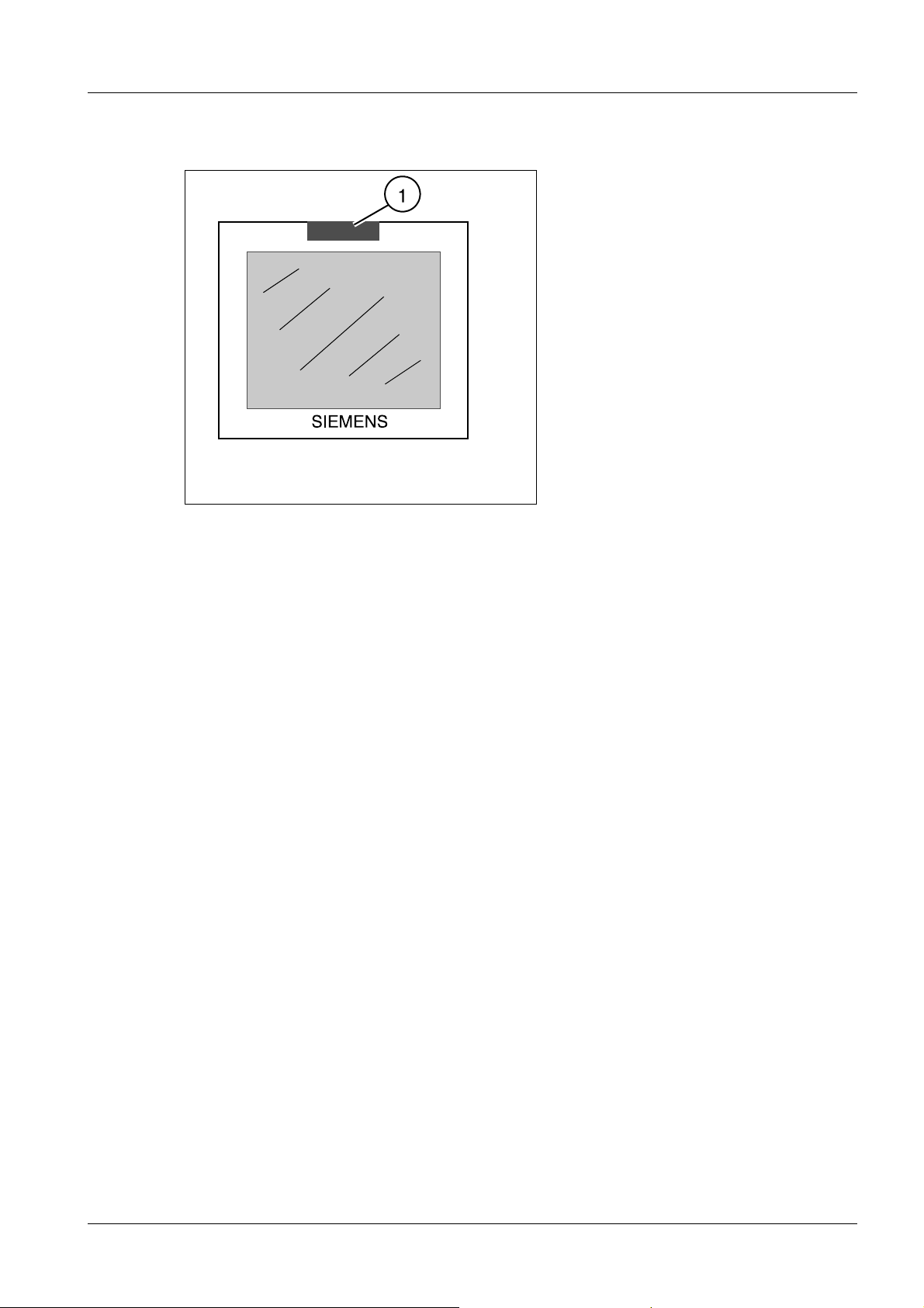
Fig. 47: Adhesive label
• Attach the "LITHOSTAR MODULARIS" label included in the shipment to the monitor of
the ultrasound unit (1/Fig. 47 / p. 45) (this label is used to identify which ultrasound unit
is functioning with the LITHOSTAR MODULARIS).
Siemens AG SPL1-130.814.02.07.02 MODULARIS Litho Vario
Medical Solutions
02.05 CS PS 24
Page 45 of 88
Page 46

46 Start-up
MUT MODULARIS 0
The endoscopy trolley will be started up by the corresponding supplier.
MODULARIS Litho Vario SPL1-130.814.02.07.02 Siemens AG
02.05 CS PS 24
Page 46 of 88
Medical Solutions
Page 47

Start-up 47
Final work steps 0
See chapter (Final work steps / p. 84).
Siemens AG SPL1-130.814.02.07.02 MODULARIS Litho Vario
Medical Solutions
02.05 CS PS 24
Page 47 of 88
Page 48

48 Ultrasound localization retrofit
4Ultrasound localization retrofit
5-
Fig. 48: Removing the cover panel
Fig. 49: Attachments 1
Fig. 50: Overview 1
• Remove the cover from the trolley.
MODULARIS Litho Vario SPL1-130.814.02.07.02 Siemens AG
02.05 CS PS 24
Page 48 of 88
Medical Solutions
Page 49

Ultrasound localization retrofit 49
• Remove each of the 4 cover panels of the installation openings for the parts
(2/3/Fig. 49 / p. 48).
• Check whether the bottom installation openings for the part (3/Fig. 49 / p. 48) are ac-
cessible. If not, mark them on the cover panel.
• Remove the shock wave head and take out the cable (1/Fig. 48 / p. 48).
• Check that connector X28 is connected to board D3. If not, connect it. Pull the entire ex-
cess length of this cable to the shock wave head if not already done.
• If necessary, file open the installation opening on the cover panel for the part
(3/Fig. 49 / p. 48).
Fig. 51: Controller 1
Fig. 52: Controller 2
• Reattach the cover panel and guide the cable (1/Fig. 49 / p. 48) out of it.
NOTE
In the case of newer installation parts, the sleeves are already connected to the installation parts.
• Secure the parts (2/3/Fig. 49 / p. 48) with the loose spacer sleeve.
Attachment:
Siemens AG SPL1-130.814.02.07.02 MODULARIS Litho Vario
Medical Solutions
02.05 CS PS 24
Page 49 of 88
Page 50

50 Ultrasound localization retrofit
- (a/Fig. 49 / p. 48): long sleeve, screw: M5 x 40 mm
- (b/Fig. 49 / p. 48): short sleeve, screw: M5 x 21 mm
- (c/Fig. 49 / p. 48): short sleeve, screw: M5 x 24 mm.
• Remove the controller cover (1/Fig. 51 / p. 49).
• The retaining pins are already mounted on the board (AS 03).
- Place the additional MUP D3 board from the conversion kit in position
(1/Fig. 52 / p. 49) and screw it in place.
• Before mounting the retaining pins on the board:
- Remove all wires.
- Remove the controller.
- Remove the board from the mount.
- Mount the retaining pins.
- Screw the board to the mount again.
- Place the additional MUP D3 board from the conversion kit in position
(1/Fig. 52 / p. 49) and screw it in place.
- Reinstall the controller.
- Reconnect all cables.
• Reattach the controller cover (1/Fig. 51 / p. 49).
Fig. 53: Connector mount
MODULARIS Litho Vario SPL1-130.814.02.07.02 Siemens AG
02.05 CS PS 24
Page 50 of 88
Medical Solutions
Page 51

Ultrasound localization retrofit 51
Fig. 54: Mount 1
Fig. 55: Mount 2
• Unscrew the mount (1/Fig. 54 / p. 51) (to facilitate installation of the cables at a later
point, mark the length and position).
• If none of the three connector mounts (Fig. 53 / p. 50) is present yet, drill a 2.5 mm hole
(see: (Fig. 53 / p. 50)). Mount the connector mount in the same way as the adjacent
ones.
• Connect the cable from the conversion kit to the D3.X29 board in the MODULARIS Var-
io.
• Screw down the mount (1/Fig. 54 / p. 51) again with the three old cables and the new
cable.
Siemens AG SPL1-130.814.02.07.02 MODULARIS Litho Vario
Medical Solutions
02.05 CS PS 24
Page 51 of 88
Page 52

52 Ultrasound localization retrofit
Cable mount on the support arm 0
• Use the screw included in the shipment instead of the cover panel screw to install the
mount (1/Fig. 55 / p. 51).
MODULARIS Litho Vario SPL1-130.814.02.07.02 Siemens AG
02.05 CS PS 24
Page 52 of 88
Medical Solutions
Page 53

Ultrasound localization retrofit 53
Cable holder on the cable 0
Fig. 56: Mount 3
Fig. 57: Connector 1
• If the holder (1/Fig. 56 / p. 53) is not yet located on the cable for the ultrasound mount,
proceed as follows:
- Unscrew the connectors: Hold the part (1/Fig. 57 / p. 53) and turn part 2
(2/Fig. 57 / p. 53).
- Slide the holder (1/Fig. 56 / p. 53) onto part 2 (the depression must point toward part
2).
- Screw the connectors together again.
Siemens AG SPL1-130.814.02.07.02 MODULARIS Litho Vario
Medical Solutions
02.05 CS PS 24
Page 53 of 88
Page 54

54 Ultrasound localization retrofit
Ultrasound probes 0
• Prepare the sector probe/array probe according to this document.
MODULARIS Litho Vario SPL1-130.814.02.07.02 Siemens AG
02.05 CS PS 24
Page 54 of 88
Medical Solutions
Page 55

Ultrasound localization retrofit 55
Adhesive labels for ultrasound unit 0
Fig. 58: Adhesive label
• Attach the "MODULARIS Vario" label included in the shipment to the monitor of the ul-
trasound unit (1/Fig. 58 / p. 55) (this label is used to identify which ultrasound unit is
functioning with the MODULARIS Vario).
Siemens AG SPL1-130.814.02.07.02 MODULARIS Litho Vario
Medical Solutions
02.05 CS PS 24
Page 55 of 88
Page 56

56 Ultrasound localization retrofit
Adjustment and start-up 0
• Switch on the system.
• Set the S2 switch on the D3 board to the service position.
• Connect the service PC and establish the connection (see the service instructions).
• Adjust the potentiometer in the ultrasound mount.
See Service Instructions, SPL1-130.061.01..
• Install the software for the ultrasound unit, according to unit type.
• Enable ultrasound localization ("Selecting the MODULARIS cross.....")
X
• .
• Check the isocenter with X-ray.
• Check the isocenter as described in this document.
MODULARIS Litho Vario SPL1-130.814.02.07.02 Siemens AG
02.05 CS PS 24
Page 56 of 88
Medical Solutions
Page 57

Ultrasound localization retrofit 57
LithoShare with several ultrasound units 0
Perform for each ultrasound unit.
SONOLINE G20 0
Fig. 59: SONOLINE G20
• Secure the connector adapter (1/Fig. 59 / p. 57) to the serial interface.
• Install software version V1.0.302 or higher in the SONOLINE G20 (see the SONOLINE
G20 operating instructions, chapter 4).
• Enable ultrasound localization (chapter: “Selecting the MODULARIS cross at the
SONOLINE G20”).
Siemens AG SPL1-130.814.02.07.02 MODULARIS Litho Vario
Medical Solutions
02.05 CS PS 24
Page 57 of 88
Page 58

58 Ultrasound localization retrofit
SONOLINE Adara 0
Fig. 60: SONOLINE Adara
• Secure the connector adapter (1/Fig. 60 / p. 58) to the serial interface.
• Install software version 2.0.0 in the SONOLINE Adara (see the SONOLINE Adara oper-
ating instructions, chapters 7-19).
- Only available with SONOLINE Adara:
Prior to installing the new software V.2.0.0, save the "presettings" and "quick sets"
(see the SONOLINE Adara operating instructions, chapters 7-15....).
After software installation, reload the stored presets in the ultrasound system (see
the SONOLINE Adara operating instructions, chapters 7-17).
• Enable ultrasound localization (chapter: “Selecting the MODULARIS cross at the
SONOLINE Adara”).
MODULARIS Litho Vario SPL1-130.814.02.07.02 Siemens AG
02.05 CS PS 24
Page 58 of 88
Medical Solutions
Page 59

Ultrasound localization retrofit 59
SONOLINE Prima 0
Fig. 61: SONOLINE Prima
• Install the connector adapter (1/Fig. 61 / p. 59).
• Install software version 2.8.0 in the SONOLINE Prima (see the SONOLINE Prima oper-
ating instructions, chapters 8-22).
- Only available with SONOLINE Prima:
Prior to installing the software V.2.8.0, save the "user presets" and "quick sets" (see
the SONOLINE Prima operating instructions, chapters 8-16....).
After software installation, reload the stored presets in the ultrasound system (see
the SONOLINE Prima operating instructions.)
• Enable ultrasound localization (chapter: “Selecting the MODULARIS cross at the
SONOLINE Prima”).
• Attach the "MODULARIS Vario" label included in the shipment to the monitor of the ul-
trasound unit (1/Fig. 58 / p. 55) (this label is used to identify which ultrasound unit is
functioning with the MODULARIS Vario).
• Prepare the ultrasound probes.
• Check the isocenter as described in this document.
Siemens AG SPL1-130.814.02.07.02 MODULARIS Litho Vario
Medical Solutions
02.05 CS PS 24
Page 59 of 88
Page 60
60 Isocenter with ultrasound
5Isocenter with ultrasound
6-
Preparations 0
Fig. 62: View of unit
Fig. 63: Probe 01
MODULARIS Litho Vario SPL1-130.814.02.07.02 Siemens AG
02.05 CS PS 24
Page 60 of 88
Medical Solutions
Page 61

Isocenter with ultrasound 61
Fig. 64: Probe_2
NOTE
Only approved probes may be used for the corresponding SONOLINE.
• Install the mount (1/Fig. 62 / p. 60) (see also operating instructions).
• Insert one of the ultrasound probes (sector probe (1/Fig. 63 / p. 60) or array probe
((2/Fig. 63 / p. 60) or (3/Fig. 64 / p. 61)) into the mount (3/Fig. 62 / p. 60). Carefully lay
the cable for the probe in the long slot (4/Fig. 62 / p. 60).
• Plug in the cable (2/Fig. 62 / p. 60) and connect the probe to the ultrasound unit.
• Make the line connection (marked orange) between the MODULARIS Vario and the ul-
trasound unit.
Siemens AG SPL1-130.814.02.07.02 MODULARIS Litho Vario
Medical Solutions
02.05 CS PS 24
Page 61 of 88
Page 62

62 Isocenter with ultrasound
Checking the target on the SONOLINE G20 0
Fig. 65: Target_Test_1
Fig. 66: Target_Test_2
NOTE
The isocenter must be checked with every probe type and after every replacement of a probe.
NOTE
The button designations can vary depending on the language version.
See the SONOLINE operating instructions for a comparison table.
MODULARIS Litho Vario SPL1-130.814.02.07.02 Siemens AG
02.05 CS PS 24
Page 62 of 88
Medical Solutions
Page 63

Isocenter with ultrasound 63
• Use the ”image field/zoom“ knob to set the value (1/Fig. 66 / p. 62) to 180.
• Slide the ultrasound probe all the way forward to the shock wave head.
• Press the “Measurement” key and select the “Set” measurement marker.
• Use the track ball to move to the center of the crosshair. A value of 13 mm ± 1 mm
(2/Fig. 65 / p. 62) must appear in the display (2/Fig. 65 / p. 62) .
• Press the “Measurement” key (“Freeze” is deselected).
• Move the ultrasound probe all the way in the other direction.
• Press the “Measurement” key and select the “Set” measurement marker.
• Use the track ball to move to the center of the crosshair. A value of 151 mm ± 1 mm
must appear in the display (2/Fig. 66 / p. 62).
If this is not the case, the adjustment procedure must be repeated for the potentiometer
in the ultrasound arm or the ultrasound arm must be replaced.
Fig. 67: Phantom 2
Fig. 68: Water bubble
Siemens AG SPL1-130.814.02.07.02 MODULARIS Litho Vario
Medical Solutions
02.05 CS PS 24
Page 63 of 88
Page 64

64 Isocenter with ultrasound
Checking image tilt 0
NOTE
The isocenter must be checked with every probe type and after every replacement of a probe.
• Check whether the isocenter phantom (1/Fig. 67 / p. 63) is filled with water. If not, re-
move the screw (2/Fig. 67 / p. 63) and fill in water with a syringe (3/Fig. 67 / p. 63).
There may not be any air bubbles. Screw in the screw again.
• Lift up the isocenter phantom.
• Fill the water bladder with water (approx. 100-120 ml, i.e. 5-6 syringes, each 20 ml)
(1/Fig. 68 / p. 63):
- Fill a syringe with distilled water. Remove any air that may be trapped in the syringe.
- Insert the syringe needle through one of the valves (2/Fig. 68 / p. 63) and inject the
contents of the syringe into the water bladder. The valve has a self-closing membrane.
- Repeat the fill operation until the water bladder is filled with approx. 100-120 ml of
water.
- After filling, there may not be any air bubbles in the water bladder. Remove the air
bubbles with the syringe.
• Spread contact gel on the isocenter phantom.
• Secure the water bladder (5/Fig. 62 / p. 60) to the isocenter phantom with the holder
(6/Fig. 62 / p. 60).
• Apply coupling gel to the ultrasound probe.
• User the “Image field/zoom” knob to set the value “50” (Fig. 69 / p. 65) - bottom left of
the ultrasound image.
• Move the probe forward (3/Fig. 62 / p. 60) until the isocenter crosshair is approx. in the
center of the SONOLINE G20 screen.
MODULARIS Litho Vario SPL1-130.814.02.07.02 Siemens AG
02.05 CS PS 24
Page 64 of 88
Medical Solutions
Page 65

Isocenter with ultrasound 65
Fig. 69: Basic settings_
Fig. 70: Ultrasound arm_
• Activate the task menu and display it.
• Make the following basic settings at the ultrasound unit:
Siemens AG SPL1-130.814.02.07.02 MODULARIS Litho Vario
Medical Solutions
02.05 CS PS 24
Page 65 of 88
Page 66

66 Isocenter with ultrasound
Value: Adjust using: German English French Spanish
5
(Fig. 69 / p.
65)
35 dB
(Fig. 69 / p.
65)
NOTE
Set track ball to
edge (white background), then actuate and set
“Select” value via
the controller.
Set track ball to DR
(white background),
then actuate and
set “Select” value
via the controller.
Each activation of the “Set” key increases the value by +1. The
“Select” controller allows the value to be changed in both directions.
FV Edge Côté Contorno
DR Dyn Rng DR Cam Din
• Set all slide controls all the way to the left.
• Press Image reverse may not be selected.
• The corresponding ultrasound probe is selected during switch-on. If there is a sec-
ond ultrasound probe, select the probe with the key.
• Check whether the ultrasound arm is positioned as shown in (Fig. 62 / p. 60). If not,
position it accordingly. The long slot must be visible (1/Fig. 70 / p. 65).
Checking the distance: Height
Fig. 71: Distance_height
MODULARIS Litho Vario SPL1-130.814.02.07.02 Siemens AG
02.05 CS PS 24
Page 66 of 88
Medical Solutions
Page 67

Isocenter with ultrasound 67
• Press the “Measurement” key.
• Use the track ball to place the cross on the center of the target cross.
• Press the Measurement key.
• Move the track ball until the cross is in the center of the isocenter cross.
• Press the Measurement key.
• Use the track ball to move the “+2” cross to the longitudinal axis of the target line into
the isocenter.
• Press
the
key.
• Move the cross using the track ball horizontally into the center of the white area of the
isocenter phantom.
• The value displayed for “D2” must be between 1 and 5 mm. This is only valid for the
default values, see instructions, SPL1-130.038.01... .
• Press
the
Checking the distance: Page
• Press
the
key.
key twice ("+1" cross is not necessary for this measurement).
• Use the track ball to move the “+2” cross to the longitudinal axis of the target line at
the height of the isocenter.
• Press
the
key.
• Move the cross using the track ball horizontally into the center of the white area of the
isocenter phantom.
• If the center point of the white area is not in the isocenter (permissible difference ± 0.5
mm from the center):
- Make a note of the value of D2 (with mathematical sign):
If the display of the ball appears to the left of the isocenter, the correction value
must have a negative sign (to the right it must have a positive sign).
Siemens AG SPL1-130.814.02.07.02 MODULARIS Litho Vario
Medical Solutions
02.05 CS PS 24
Page 67 of 88
Page 68

68 Isocenter with ultrasound
- Press the F6 key.
- Use the track ball to select MUP.
- Press
the
- Press
the
- Enter the password.
- Select OK via the track ball.
- Press the “Set” key.
- Use the track ball to select the value during image tilt and increase it via the “Set”
key.
German: Bildneigung Array French: Basculement d'image sondes conv.
English: Image tilt array Spanish: Inclinar imagen transductor curvo
- Set half the value of D2.
Example : D2 = 1.2 mm ⇒ Enter: -06 .
“Set” key.
“5” key.
- Press
the
- Check the deviation; if white area is not in the center of the isocenter, repeat the
procedure.
key.
• After the adjustment, secure the mount for the ultrasound probe on the mounting
point (7/Fig. 62 / p. 60). For each probe, check whether the adjustment in this posi-
tion is also OK. Do not make any change to the image tilt adjustment.
• Following the check, store the parts in the appropriate transport cases.
MODULARIS Litho Vario SPL1-130.814.02.07.02 Siemens AG
02.05 CS PS 24
Page 68 of 88
Medical Solutions
Page 69

Isocenter with ultrasound 69
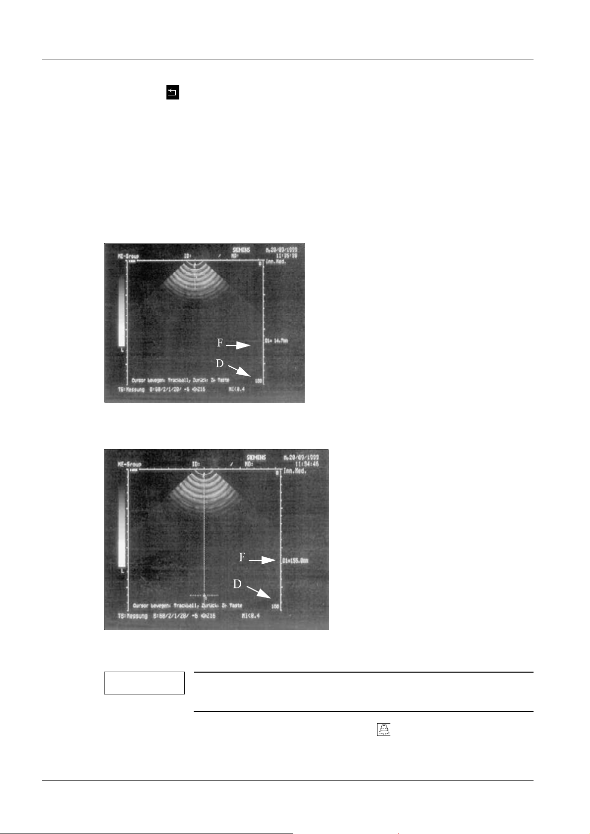
Checking the target on the Sonoline Adara 0
Fig. 72: Target test 1
Fig. 73: Target test 2
NOTE
The isocenter must be checked for every probe type and after every replacement of a probe.
• Set the value (D/Fig. 72 / p. 69) via the knob to 180.
• Press the key and select the measurement
marker.
• Use the track ball to move to the center of the crosshairs. A value accord-
ing to the table must appear in the display (F/Fig. 72 / p. 69) as a function
of the probe.
Siemens AG SPL1-130.814.02.07.02 MODULARIS Litho Vario
Medical Solutions
02.05 CS PS 24
Page 69 of 88
Page 70

70 Isocenter with ultrasound
Probe Changeover
with
Page(1/Fig. 63 / p. 60) 15 ±1 mm for default values, see
Array (2/Fig. 63 / p. 60) 13 ±1 mm
Value for D1
SPL1-130.038.01..
• Press the key (“Freeze” is deselected).
• Move the ultrasound probe all the way in the other direction.
• Press the key and select the measurement
marker.
• Use the track ball to move to the center of the crosshair. A value according to
the table must appear in the display (F/Fig. 73 / p. 69) as a function of the
probe.
If this is not the case, the adjustment procedure must be repeated for the potentiometer in the ultrasound arm or the ultrasound arm must be replaced.
Probe Changeover
with
Page(1/Fig. 63 / p. 60) 153 ± 1 mm for default values, see
Array (2/Fig. 63 / p. 60) 151 ±1 mm
Value for D1
SPL1-130.038.01..
• Press the key ("Freeze" is deselected).
Checking image tilt 0
NOTE
The isocenter must be checked for every probe type and after every replacement of a probe.
MODULARIS Litho Vario SPL1-130.814.02.07.02 Siemens AG
02.05 CS PS 24
Page 70 of 88
Medical Solutions
Page 71

Isocenter with ultrasound 71
Fig. 74: Phantom 2
Fig. 75: Water bubble
• Check whether the isocenter phantom (1/Fig. 74 / p. 71) is filled with water. If not, re-
move the screw (2/Fig. 74 / p. 71) and fill in water with a syringe (3/Fig. 74 / p. 71).
There may not be any air bubbles. Screw in the screw again.
• Lift up the isocenter phantom.
• Fill the water bladder with water (approx. 100-120 ml, i.e. 5-6 syringes, each 20 ml)
(1/Fig. 75 / p. 71):
- Fill a syringe with distilled water. Remove any air that may be trapped in the syringe.
- Insert the syringe needle through one of the valves (2/Fig. 75 / p. 71) and inject the
contents of the syringe into the water bladder. The valve has a self-closing membrane.
- Repeat the fill operation until the water bladder is filled with approx. 100-120 ml of
water.
- After filling, there may not be air bubbles in the water bladder. Remove any air bubbles with the syringe.
Siemens AG SPL1-130.814.02.07.02 MODULARIS Litho Vario
Medical Solutions
02.05 CS PS 24
Page 71 of 88
Page 72

72 Isocenter with ultrasound
• Spread contact gel on the isocenter phantom.
• Secure the water bladder (5/Fig. 62 / p. 60) to the isocenter phantom with the holder
(6/Fig. 62 / p. 60).
• Apply coupling gel to the ultrasound probe.
• Use the knob
to set
the value “60” (D/Fig. 69 / p. 65).
• Move the probe forward (3/Fig. 62 / p. 60) until the isocenter crosshair is approx. in
the center of the SONOLINE Prima screen.
Fig. 76: Basic settings
Fig. 77: Ultrasound arm
MODULARIS Litho Vario SPL1-130.814.02.07.02 Siemens AG
02.05 CS PS 24
Page 72 of 88
Medical Solutions
Page 73

Isocenter with ultrasound 73
• Make the following basic settings at the ultrasound unit:
Value: Adjust using: German English French Spanish
- 6 dB
(C/Fig. 76 / p.
72)
20 dB
(B/Fig. 76 / p.
72)
3
(A/Fig. 76 / p.
72)
60
(D/Fig. 76 / p.
72)
60 dB
(E/Fig. 76 / p.
72)
Knob
Knob EV Gain Gain Ampl
Set the track ball to
FV (highlighted in
white),
and then press .
Knob ------- ------- ------- -------
Knob DR Dyn Rng DR Cam Din
SI Output Sortie Salida
FV Edge Côté Contorno
Fig. 78: Checks_02
• Set the slide controls all the way to the left.
• Press Image reverse may not be selected.
• Select the appropriate ultrasound probe:
Sector probe Array probe
Siemens AG SPL1-130.814.02.07.02 MODULARIS Litho Vario
Medical Solutions
02.05 CS PS 24
Page 73 of 88
Page 74

74 Isocenter with ultrasound
• Check whether the ultrasound arm is positioned as shown in (Fig. 77 / p. 72). If not, po-
sition it accordingly. The long slot must be visible (1/Fig. 77 / p. 72).
Checking the distance: Height (16a/Fig. 78 / p. 73)
• Press
the
key.
• Move the track ball until the “+1” cross is in the center of the isocenter cross.
• The value displayed for “D1” (G/Fig. 78 / p. 73) must be between 33 and 36 mm; if not,
move the probe appropriately in the longitudinal axis.
• Press
the
key.
• Use the track ball to move the “+2” cross to the longitudinal axis of the target line into
the isocenter (M/16a/Fig. 78 / p. 73).
• Press the key.
• Move the “+2” cross using the track ball horizontally into the center of the white area
(16a/Fig. 78 / p. 73) of the isocenter phantom.
• The value displayed for “D2” (H/Fig. 78 / p. 73) must be between 1 and 5 mm. This is
only valid for the default values, see instructions, SPL1-130.038.01... .
• Press
the
Checking the distance: Page (16b/Fig. 78 / p. 73)
• Press
the
key.
key twice (“+1” cross is not necessary for this measurement).
• Move the “+2” cross using the track ball onto the horizontal axis of the target line
(C/Fig. 78 / p. 73).
• Press
the
key.
MODULARIS Litho Vario SPL1-130.814.02.07.02 Siemens AG
02.05 CS PS 24
Page 74 of 88
Medical Solutions
Page 75

Isocenter with ultrasound 75
• Move the “+2” cross using the track ball horizontally into the center of the white area
of the isocenter phantom.
• If the center point of the white area (16b/Fig. 78 / p. 73) is not in the isocenter (per-
missible difference ± 0.5 mm from the center):
- Make a note of the value of D2 (with mathematical sign):
If the display of the ball (16b/Fig. 78 / p. 73) appears to the left of the isocenter,
the correction value must have a negative sign (to the right it must have a positive sign).
-Press
the
- Press the "F4" key.
- Press the "5" key.
- Select "MUP" with the track ball.
-Press
the
- Enter the password.
- Use the track ball to select the appropriate probe during image tilt.
German: Bildkippung Sektor
Bildkippung Array
English: Image Tilt Sector
Image Tilt Array
key.
key.
French: Basculement d'image sondes sect.
Basculement d'image sondes
conv.
Spanish: Incl. imagen transd. sect meca-
nico Inclinar imagen transductor
curvo
- Press
the
- Set half the value of D2 (H/Fig. 78 / p. 73).
Example (H/Fig. 78 / p. 73) D2 = 1.2 mm ⇒ Enter: -06
- Press
the
- Press
the
- Check the deviation; if the white area (16b/Fig. 78 / p. 73) is not in the center of
the isocenter, repeat the procedure.
Siemens AG SPL1-130.814.02.07.02 MODULARIS Litho Vario
Medical Solutions
02.05 CS PS 24
key.
key.
key twice.
Page 75 of 88
Page 76
76 Isocenter with ultrasound
• Press
the
key.
• After the adjustment, secure the mount for the ultrasound probe on the mounting point
(7/Fig. 62 / p. 60). For each probe, check whether the adjustment in this position is also
OK. Do not make any change to the image tilt adjustment.
• Following the check, store the parts in the appropriate transport cases.
Checking the target on the Sonoline Prima 0
Fig. 79: Target test 1
Fig. 80: Target test 2
NOTE
The isocenter must be checked for every probe type and after every replacement of a probe.
• Set the value (D/Fig. 79 / p. 76) via the knob to 180.
MODULARIS Litho Vario SPL1-130.814.02.07.02 Siemens AG
02.05 CS PS 24
Page 76 of 88
Medical Solutions
Page 77

Isocenter with ultrasound 77
• Slide the ultrasound probe all the way forward to the shock wave head.
• Press the key and select the measurement
marker.
• Use the track ball to move to the center of the crosshair. A value of D1 accord-
ing to the table must appear in the display (F/Fig. 79 / p. 76) as a function of
the probe.
Probe Select using Value for D1
Page (1/Fig. 63 / p. 60) 15 ±1 mm for default values, see
Array (2/Fig. 63 / p. 60) 13 ±1 mm
SPL1-130.038.01..
• Press the key (“Freeze” is deselected).
• Move the ultrasound probe all the way in the other direction.
• Press the key and select the measurement
marker.
• Use the track ball to move to the center of the crosshair. A value of D1 according
to the table must appear in the display (F/Fig. 80 / p. 76) as a function of the
probe. If this is not the case, the adjustment procedure must be repeated for the
potentiometer in the ultrasound arm or the ultrasound arm must be replaced.
Probe Select using Value for D1
Page (1/Fig. 63 / p. 60) 153 ±1 mm for default values, see
Array (2/Fig. 63 / p. 60) 151 ±1 mm
SPL1-130.038.01..
• Press the key (“Freeze” is deselected).
Siemens AG SPL1-130.814.02.07.02 MODULARIS Litho Vario
Medical Solutions
02.05 CS PS 24
Page 77 of 88
Page 78

78 Isocenter with ultrasound
Checking image tilt 0
NOTE
Fig. 81: Phantom 2
The isocenter must be checked for every probe type and after every replacement of a probe.
Fig. 82: Water bubble
• Check whether the isocenter phantom (1/Fig. 81 / p. 78) is filled with water. If not, re-
move the screw (2/Fig. 81 / p. 78) and fill in water with a syringe (3/Fig. 81 / p. 78).
There may not be any air bubbles. Screw in the screw again.
• Lift up the isocenter phantom.
• Fill the water bladder with water (approx. 100-120 ml, i.e. 5-6 syringes, each 20 ml)
(1/Fig. 82 / p. 78):
- Fill a syringe with distilled water. Remove any air that may be trapped in the syringe.
MODULARIS Litho Vario SPL1-130.814.02.07.02 Siemens AG
02.05 CS PS 24
Page 78 of 88
Medical Solutions
Page 79

Isocenter with ultrasound 79
- Insert the syringe needle through one of the valves (2/Fig. 82 / p. 78) and inject the
contents of the syringe into the water bladder. The valve has a self-closing membrane.
- Repeat the fill operation until the water bladder is filled with approx. 100-120 ml of
water.
- After filling, there may not be air bubbles in the water bladder. Remove any air bubbles with the syringe.
• Spread contact gel on the isocenter phantom.
• Secure the water bladder (5/Fig. 62 / p. 60) to the isocenter phantom with the holder
(6/Fig. 62 / p. 60).
• Apply coupling gel to the ultrasound probe.
• Use the knob to set the value “60”
(D/Fig. 83 / p. 79)
.
• Move the probe forward (3/Fig. 62 / p. 60) until the isocenter crosshair is approx. in
the center of the SONOLINE Prima screen.
Fig. 83: Basic settings
Siemens AG SPL1-130.814.02.07.02 MODULARIS Litho Vario
Medical Solutions
02.05 CS PS 24
Page 79 of 88
Page 80

80 Isocenter with ultrasound
Fig. 84: Ultrasound arm
• Make the following basic settings at the ultrasound unit:
Value: Adjust using: German English French Spanish
- 6 dB
(C/Fig. 83 / p.
79)
20 dB
Knob
SI Output Sortie Salida
Knob EV Gain Gain Ampl
(B/Fig. 83 / p.
79)
3
(A/Fig. 83 / p.
79)
Set the track ball to
FV (highlighted in
white),
FV Edge Côté Contorno
and then press .
60
Knob ------- ------- ------- -------
(D/Fig. 83 / p.
79)
60 dB
Knob DR Dyn Rng DR Cam Din
(E/Fig. 83 / p.
79)
MODULARIS Litho Vario SPL1-130.814.02.07.02 Siemens AG
02.05 CS PS 24
Page 80 of 88
Medical Solutions
Page 81

Isocenter with ultrasound 81
Fig. 85: Checks_02
• Set the slide controls all the way to the left.
• Press Image reverse may not be selected.
• Select the appropriate ultrasound probe:
Sector probe Array probe
• Check whether the ultrasound arm is positioned as shown in (Fig. 84 / p. 80). If not, po-
sition it accordingly. The long slot must be visible (1/Fig. 84 / p. 80).
Checking the distance: Height (16a/Fig. 85 / p. 81)
• Press
the
key.
• Move the track ball until the “+1” cross is in the center of the isocenter cross.
• The value displayed for “D1” (G/Fig. 85 / p. 81) must be between 33 and 36 mm; if not,
move the probe appropriately in the longitudinal axis.
• Press
the
key.
• Use the track ball to move the “+2” cross to the longitudinal axis of the target line into
the isocenter (16a/Fig. 85 / p. 81).
• Press the key.
Siemens AG SPL1-130.814.02.07.02 MODULARIS Litho Vario
Medical Solutions
02.05 CS PS 24
Page 81 of 88
Page 82

82 Isocenter with ultrasound
• Move the “+2” cross using the track ball horizontally into the center of the white area
(16a/Fig. 85 / p. 81) of the isocenter phantom.
• The value displayed for “D2” (H/Fig. 85 / p. 81) must be between 1 and 5 mm. This is
only valid for the default values, see instructions SPL1-130.038.01... .
• Press
the
Checking the distance: Page (16a/Fig. 85 / p. 81)
• Press
the
key.
key twice (“+1” cross is not necessary for this measurement).
• Move the “+2” cross using the track ball onto the horizontal axis of the target line
(C/Fig. 85 / p. 81).
• Press
the
key.
• Move the “+2” cross using the track ball horizontally into the center of the white area
of the isocenter phantom.
• If the center point of the white area (16b/Fig. 85 / p. 81) is not in the isocenter (per-
missible difference ± 0.5 mm from the center):
- Make a note of the value of D2 (with mathematical sign):
If the display of the ball (16b/Fig. 85 / p. 81) appears to the left of the isocenter,
the correction value must have a negative sign (to the right it must have a positive sign).
-Press
the
- Press the "F4" key.
- Press the "5" key.
- Select "MUP" with the track ball.
-Press
the
- Enter the password.
- Use the track ball to select the appropriate probe during image tilt.
MODULARIS Litho Vario SPL1-130.814.02.07.02 Siemens AG
02.05 CS PS 24
key.
key.
Page 82 of 88
Medical Solutions
Page 83

Isocenter with ultrasound 83
German: Bildkippung Sektor
Bildkippung Array
English: Image Tilt Sector
Image Tilt Array
- Press
the
- Set half the value of D2 (H/Fig. 85 / p. 81).
Example (H/Fig. 85 / p. 81) D2 = 1.2 mm ⇒ Enter: -06
- Press
the
- Press
the
- Check the deviation; if the white area (16b/Fig. 85 / p. 81) is not in the center of
the isocenter, repeat the procedure.
key.
key.
key twice.
French: Basculement d'image sondes sect.
Basculement d'image sondes
conv.
Spanish: Incl. imagen transd. sect meca-
nico Inclinar imagen transductor
curvo
• Press
the
key.
• After the adjustment, secure the mount for the ultrasound probe on the mounting point
(7/Fig. 62 / p. 60). For each probe, check whether the adjustment in this position is also
OK. Do not make any change to the image tilt adjustment.
• Following the check, store the parts in the appropriate transport cases.
Siemens AG SPL1-130.814.02.07.02 MODULARIS Litho Vario
Medical Solutions
02.05 CS PS 24
Page 83 of 88
Page 84

84 Final work steps
6Final work steps
7-
Customer and country-specific settings 0
Setting the system clock (if necessary) 0
• MODULARIS Vario on.
• Set the service switch in M13/D3/S2 to position 2 (service on).
• Select "service" on the control panel and then "set clock".
• Select the corresponding item and change the setting.
• Set the service switch in M13/D3/S2 to position 1 (service off).
Setting the user language (if necessary) 0
• Set the service switch in M13/D3/S2 to position 2 (service on).
• Select "Service" on the control panel, then "System data", and then "Language".
• Using button S5/S6, select the required language and then activate S2 (back).
• Set the service switch in M13/D3/S2 to position 1 (service off).
MODULARIS Litho Vario SPL1-130.814.02.07.02 Siemens AG
02.05 CS PS 24
Page 84 of 88
Medical Solutions
Page 85

Final work steps 85
Backup and error memory 0
• When the start-up is complete, perform a backup and then erase the error memory
(e:show error log) (see Service Instructions).
• Delete the therapy data (t:show therapy data).
Siemens AG SPL1-130.814.02.07.02 MODULARIS Litho Vario
Medical Solutions
02.05 CS PS 24
Page 85 of 88
Page 86

86 Final work steps
Remaining work 0
• Connect and secure the protective conductors to all the covers.
• Measure the protective conductor resistance.
Measurement
device:
Measured
value:
Measurement
procedure:
Conditions: Protective conductor resistance max. 0.2 ohms
Protective conductor
meter
max. 0.2 ohms (Ensure compliance with country-specific
regulations.)
(Current 10 A, voltage drop max. 2 V)
Measure between all accessible, conductive parts of the system
and the protective conductor rail in the generator.
• Reduce the contact resistance (e.g. tighten the screws)
• If necessary, increase the diameter of the protective conductor.
• Cleaning the MODULARIS Vario:
For information on cleaning the system, refer to the chapter on "Cleaning/Disinfecting"
in the operating instructions.
• The manufacturer of this product requires information and the legislator demands
proofs that a product delivered free of defects from the factory continues to possess the
required and certified quality properties on installation and start-up. It is therefore absolutely necessary that the installation report with the installation and start-up data is sent
without delay after completion of the work to the address stated on the installation report. The report is available in the system binder.
• File the fax for the release for operation in the system binder. If the C-arm unit is not
from Siemens, include the dimension protocol from the PG.
NOTICE
Fill out the protocols.
¹ After completing all adjustments and measurements, the
responsible service engineer should confirm that all the
values have been correctly measured and recorded in
the measurement protocols by signing his name and the
date (system, generator and IQ measurement protocol).
MODULARIS Litho Vario SPL1-130.814.02.07.02 Siemens AG
02.05 CS PS 24
Page 86 of 88
Medical Solutions
Page 87

Changes to previous version 87
7Changes to previous version
8-
Chapter 7 (Final Work
Steps):
• Remaining work
- Reference to the installation report added
Siemens AG SPL1-130.814.02.07.02 MODULARIS Litho Vario
Medical Solutions
02.05 CS PS 24
Page 87 of 88
Page 88

88 Changes to previous version
MODULARIS Litho Vario SPL1-130.814.02.07.02 Siemens AG
02.05 CS PS 24
Page 88 of 88
Medical Solutions
 Loading...