

Page 1

Table of Contents
MOBY
STG Hand-Held Terminal
User’s Guide
General
Commissioning the STG
Using the STG
The “MOBY D/E/F/I/U”
Programs
The “FILEHANDLER”
Program
Expanded Functions
The “MOBY D/E/F/I/U”
Programs with the
PSION Numeric Model
1
2
3
4
5
6
7
(5)J31069-D0126-U001-A5.1-7418
Error Messages
Technical Data
Appendix
8
9
A
Published in January 2004
Page 2

Safety Guidelines
This manual contains notices which you should observe to ensure your own personal safety, as well as to protect the product and connected equipment. These
notices are highlighted in the manual by a warning triangle and are marked as
follows according to the level of danger:
Note
draws your attention to particularly important information on the product,
handling the product, or to a particular part of the documentation.
Qualified Personnel
The device/system may only be set up and operated in conjunction with this
manual.
Only qualified personnel should be allowed to install and work on this equipment. Qualified persons are defined as persons who are authorized to commission, to ground, and to tag circuits, equipment, and systems in accordance with
established safety practices and standards.
Correct Usage
Note the following:
Warning
!
This device and its components may only be used for the applications described in the catalog or the technical description, and only in connection
with devices or components from other manufacturers which have been
approved or recommended by Siemens.
This product can only function correctly and safely if it is transported,
stored, set up, and installed correctly, and operated and maintained as
recommended.
Trademarks
MOBYR is a trademark of SIEMENS AG.
Some of the other designations used in these documents are also registered
trademarks; the owner’s rights may be violated if they are used be third parties
for their own purposes.
Disclaimer of LiabilityCopyright E Siemens AG 1999 All rights reserved
The reproduction, transmission or use of this
document or its contents is not permitted without
express written authority. Offenders will be liable for
damages. All rights, including rights created by patent
grant or registration of a utility model or design, are
reserved.
Siemens AG
Automation and Drives Group
Division Special Products,
Projects Automotive Industry, Training
PO Box 4848, D-90327 Nuremberg
Siemens Aktiengesellschaft Order No. (5)J31069-D0126-U001-A5.1-7418
We have checked the contents of this manual for
agreement with the hardware and software described. Since deviations cannot be precluded entirely,
we cannot guarantee full agreement. However, the
data in this manual are reviewed regularly and any
necessary corrections included in subsequent editions. Suggestions for improvement are welcomed.
E Siemens AG 1999, 2000, 2002, 2003, 2004
Technical data subject to change.
Page 3

R 01.04
Table of Contents
Table of Contents
1 General E-1. . . . . . . . . . . . . . . . . . . . . . . . . . . . . . . . . . . . . . . . . . . . . . . . . . . . .
1.1 Application Areas E-1. . . . . . . . . . . . . . . . . . . . . . . . . . . . . . . . . . . . . .
1.2 Product Description E-1. . . . . . . . . . . . . . . . . . . . . . . . . . . . . . . . . . . .
1.3 FCC Information for the USA E-3. . . . . . . . . . . . . . . . . . . . . . . . . . . .
2 Commissioning the STG E-4. . . . . . . . . . . . . . . . . . . . . . . . . . . . . . . . . . . . .
2.1 Included Components E-4. . . . . . . . . . . . . . . . . . . . . . . . . . . . . . . . . .
2.2 Assembly E-5. . . . . . . . . . . . . . . . . . . . . . . . . . . . . . . . . . . . . . . . . . . . .
2.3 Turning on the Device and Setting the Operating Mode E-6. . . . .
2.4 MOBY Applications E-7. . . . . . . . . . . . . . . . . . . . . . . . . . . . . . . . . . . .
2.5 User Interface E-7. . . . . . . . . . . . . . . . . . . . . . . . . . . . . . . . . . . . . . . . .
3 Using the STG E-8. . . . . . . . . . . . . . . . . . . . . . . . . . . . . . . . . . . . . . . . . . . . . .
3.1 Keyboard E-8. . . . . . . . . . . . . . . . . . . . . . . . . . . . . . . . . . . . . . . . . . . . .
3.2 Antenna on the Read Head and Antenna Field E-9. . . . . . . . . . . .
3.2.1 MOBY D/E/F/I E-9. . . . . . . . . . . . . . . . . . . . . . . . . . . . . . . . . . . . . . . . .
3.2.2 MOBY U E-11. . . . . . . . . . . . . . . . . . . . . . . . . . . . . . . . . . . . . . . . . . . . .
3.3 Using the MOBY U Antenna E-12. . . . . . . . . . . . . . . . . . . . . . . . . . . .
3.4 Charging Function E-13. . . . . . . . . . . . . . . . . . . . . . . . . . . . . . . . . . . . .
3.5 Changing the Battery Pack of the MOBY U Antenna E-16. . . . . . .
4 The “MOBY D/E/F/I/U” Programs E-17. . . . . . . . . . . . . . . . . . . . . . . . . . . . .
4.1 Data Editor E-19. . . . . . . . . . . . . . . . . . . . . . . . . . . . . . . . . . . . . . . . . . .
4.2 MDS Functions E-21. . . . . . . . . . . . . . . . . . . . . . . . . . . . . . . . . . . . . . .
4.2.1 General Information on Read and Write-Accessing an MDS E-21.
4.2.2 Reading the MDS E-22. . . . . . . . . . . . . . . . . . . . . . . . . . . . . . . . . . . . .
4.2.3 Writing the MDS E-23. . . . . . . . . . . . . . . . . . . . . . . . . . . . . . . . . . . . . . .
4.2.4 Erasing/Initializing the MDS E-23. . . . . . . . . . . . . . . . . . . . . . . . . . . . .
4.2.5 Reading MDS Status E-24. . . . . . . . . . . . . . . . . . . . . . . . . . . . . . . . . .
4.2.6 Reading the ID Number E-25. . . . . . . . . . . . . . . . . . . . . . . . . . . . . . . .
4.2.7 Reading OTP Memory E-25. . . . . . . . . . . . . . . . . . . . . . . . . . . . . . . . .
4.2.8 Writing OTP memory E-25. . . . . . . . . . . . . . . . . . . . . . . . . . . . . . . . . .
4.2.9 Reading Raw Data E-26. . . . . . . . . . . . . . . . . . . . . . . . . . . . . . . . . . . .
4.3 File Functions E-27. . . . . . . . . . . . . . . . . . . . . . . . . . . . . . . . . . . . . . . . .
4.3.1 Loading a File E-27. . . . . . . . . . . . . . . . . . . . . . . . . . . . . . . . . . . . . . . . .
4.3.2 Saving E-27. . . . . . . . . . . . . . . . . . . . . . . . . . . . . . . . . . . . . . . . . . . . . . .
STG Hand-Held Terminal
(5)J31069-D0126-U001-A5.1-7418
E-I
Page 4

Table of Contents
4.3.3 Exiting E-27. . . . . . . . . . . . . . . . . . . . . . . . . . . . . . . . . . . . . . . . . . . . . . .
4.4 The Editor Functions E-28. . . . . . . . . . . . . . . . . . . . . . . . . . . . . . . . . . .
4.4.1 Jump to Address E-28. . . . . . . . . . . . . . . . . . . . . . . . . . . . . . . . . . . . . .
4.4.2 Display E-28. . . . . . . . . . . . . . . . . . . . . . . . . . . . . . . . . . . . . . . . . . . . . . .
4.4.3 Clear Display E-29. . . . . . . . . . . . . . . . . . . . . . . . . . . . . . . . . . . . . . . . .
4.4.4 Edit Date E-29. . . . . . . . . . . . . . . . . . . . . . . . . . . . . . . . . . . . . . . . . . . . .
4.5 The Extras Functions E-30. . . . . . . . . . . . . . . . . . . . . . . . . . . . . . . . . .
4.5.1 Communication E-30. . . . . . . . . . . . . . . . . . . . . . . . . . . . . . . . . . . . . . .
4.5.2 Password E-31. . . . . . . . . . . . . . . . . . . . . . . . . . . . . . . . . . . . . . . . . . . .
4.5.3 Antenna E-31. . . . . . . . . . . . . . . . . . . . . . . . . . . . . . . . . . . . . . . . . . . . . .
4.5.4 Address Setup E-32. . . . . . . . . . . . . . . . . . . . . . . . . . . . . . . . . . . . . . . .
4.5.5 MOBY I Setup E-33. . . . . . . . . . . . . . . . . . . . . . . . . . . . . . . . . . . . . . . .
4.5.6 MOBY E Setup E-33. . . . . . . . . . . . . . . . . . . . . . . . . . . . . . . . . . . . . . . .
4.5.7 MOBY U Setup E-34. . . . . . . . . . . . . . . . . . . . . . . . . . . . . . . . . . . . . . . .
4.5.8 SLG Status E-34. . . . . . . . . . . . . . . . . . . . . . . . . . . . . . . . . . . . . . . . . . .
R 01.04
4.6 The “?” Functions E-35. . . . . . . . . . . . . . . . . . . . . . . . . . . . . . . . . . . . .
4.6.1 Language E-35. . . . . . . . . . . . . . . . . . . . . . . . . . . . . . . . . . . . . . . . . . . .
4.6.2 About E-35. . . . . . . . . . . . . . . . . . . . . . . . . . . . . . . . . . . . . . . . . . . . . . . .
4.6.3 Version E-35. . . . . . . . . . . . . . . . . . . . . . . . . . . . . . . . . . . . . . . . . . . . . . .
5 The “FILEHANDLER” Program E-36. . . . . . . . . . . . . . . . . . . . . . . . . . . . . . .
5.1 General Information on the Filehandler E-36. . . . . . . . . . . . . . . . . . .
5.2 The Filehandler Commands E-37. . . . . . . . . . . . . . . . . . . . . . . . . . . .
5.3 View of the Editor and Directory E-39. . . . . . . . . . . . . . . . . . . . . . . . .
5.3.1 The Data Editor of the Filehandler E-39. . . . . . . . . . . . . . . . . . . . . . .
5.3.2 View of the Directory E-40. . . . . . . . . . . . . . . . . . . . . . . . . . . . . . . . . . .
5.4 The File Functions E-41. . . . . . . . . . . . . . . . . . . . . . . . . . . . . . . . . . . . .
5.4.1 Read File from MDS (Read File from Tag) E-41. . . . . . . . . . . . . . . .
5.4.2 Read File from STG RAM E-42. . . . . . . . . . . . . . . . . . . . . . . . . . . . . .
5.4.3 Write File to MDS (Write File to Tag) E-42. . . . . . . . . . . . . . . . . . . . .
5.4.4 Write File to STG RAM E-43. . . . . . . . . . . . . . . . . . . . . . . . . . . . . . . . .
5.4.5 Read Directory from MDS (Read Dir from Tag) E-43. . . . . . . . . . . .
5.4.6 Read Directory from STG RAM (Read Dir from STG RAM) E-43.
5.4.7 Example: Copy Files E-44. . . . . . . . . . . . . . . . . . . . . . . . . . . . . . . . . . .
5.5 The Commands Menu E-45. . . . . . . . . . . . . . . . . . . . . . . . . . . . . . . . .
5.5.1 New File (Create File) E-45. . . . . . . . . . . . . . . . . . . . . . . . . . . . . . . . . .
5.5.2 Delete File E-45. . . . . . . . . . . . . . . . . . . . . . . . . . . . . . . . . . . . . . . . . . . .
5.5.3 Format MDS (Tag Format) E-45. . . . . . . . . . . . . . . . . . . . . . . . . . . . . .
5.5.4 Attribute File (File Attribute) E-46. . . . . . . . . . . . . . . . . . . . . . . . . . . . .
5.5.5 MDS Status (Tag Status) E-47. . . . . . . . . . . . . . . . . . . . . . . . . . . . . . .
STG Hand-Held Terminal
E-II
(5)J31069-D0126-U001-A5.1-7418
Page 5

R 01.04
Table of Contents
5.5.6 MDS Cover E-48. . . . . . . . . . . . . . . . . . . . . . . . . . . . . . . . . . . . . . . . . . .
5.6 The Editor Functions E-48. . . . . . . . . . . . . . . . . . . . . . . . . . . . . . . . . . .
5.6.1 Display Directory E-48. . . . . . . . . . . . . . . . . . . . . . . . . . . . . . . . . . . . . .
5.6.2 Display Editor E-48. . . . . . . . . . . . . . . . . . . . . . . . . . . . . . . . . . . . . . . . .
5.6.3 Change File Size (File Size) E-49. . . . . . . . . . . . . . . . . . . . . . . . . . . .
5.6.4 Delete Display (Clear Display) E-49. . . . . . . . . . . . . . . . . . . . . . . . . .
5.6.5 Jump to Address E-49. . . . . . . . . . . . . . . . . . . . . . . . . . . . . . . . . . . . . .
5.6.6 Display Setup E-49. . . . . . . . . . . . . . . . . . . . . . . . . . . . . . . . . . . . . . . . .
5.7 The Extras Functions E-50. . . . . . . . . . . . . . . . . . . . . . . . . . . . . . . . . .
5.7.1 Parameter E-50. . . . . . . . . . . . . . . . . . . . . . . . . . . . . . . . . . . . . . . . . . . .
5.7.2 Password for Filehandler (Password for FH) E-51. . . . . . . . . . . . . .
5.7.3 Communication E-51. . . . . . . . . . . . . . . . . . . . . . . . . . . . . . . . . . . . . . .
5.8 The “?” Functions E-51. . . . . . . . . . . . . . . . . . . . . . . . . . . . . . . . . . . . .
6 Expanded Functions E-52. . . . . . . . . . . . . . . . . . . . . . . . . . . . . . . . . . . . . . . .
6.1 Storing the MDS Data on the Hand-Held Terminal E-52. . . . . . . . .
6.2 Copying MOBY Data from and to the Hand-Held Terminal E-53. .
6.2.1 What Is Needed in Addition? E-53. . . . . . . . . . . . . . . . . . . . . . . . . . . .
6.2.2 Using the PSION File Manager E-53. . . . . . . . . . . . . . . . . . . . . . . . . .
6.2.3 Organization of the READ.HEX File E-56. . . . . . . . . . . . . . . . . . . . . .
6.2.4 Organization of the READ.HX1 File E-56. . . . . . . . . . . . . . . . . . . . . .
6.3 Functions with the PSION Operating System E-56. . . . . . . . . . . . . .
6.4 Parallel Execution of Several Applications E-57. . . . . . . . . . . . . . . .
6.5 Automatic Power Saver Function E-58. . . . . . . . . . . . . . . . . . . . . . . .
6.6 Connecting SIM Devices (MOBY E/I/V) E-58. . . . . . . . . . . . . . . . . . .
6.7 System RESET E-59. . . . . . . . . . . . . . . . . . . . . . . . . . . . . . . . . . . . . . .
7 The “MOBY D/E/F/I/U” Programs with the PSION Numeric Model E-60
8 Error Messages E-61. . . . . . . . . . . . . . . . . . . . . . . . . . . . . . . . . . . . . . . . . . . . .
8.1 Error Messages with the “MOBY D/E/F/I/U” Programs E-62. . . . . .
8.2 Error Messages with the “FILEHANDLER” Program E-66. . . . . . . .
9 Technical Data E-68. . . . . . . . . . . . . . . . . . . . . . . . . . . . . . . . . . . . . . . . . . . . . .
A Appendix E-74. . . . . . . . . . . . . . . . . . . . . . . . . . . . . . . . . . . . . . . . . . . . . . . . . . .
A.1 Ordering Components for Expanded Functions E-74. . . . . . . . . . . .
A.2 Developing User Applications E-75. . . . . . . . . . . . . . . . . . . . . . . . . . .
A.3 ASCII Table E-80. . . . . . . . . . . . . . . . . . . . . . . . . . . . . . . . . . . . . . . . . . .
STG Hand-Held Terminal
(5)J31069-D0126-U001-A5.1-7418
E-III
Page 6

Table of Contents
R 01.04
E-IV
STG Hand-Held Terminal
(5)J31069-D0126-U001-A5.1-7418
Page 7

R 01.04
General
1 General
The STG (service and test device) is a powerful addition to the MOBY D,
MOBY E, MOBY F, MOBY I or MOBY U identification systems. It is a mobile
hand-held terminal based on the PSION Workabout mx and is designed for applications in the areas of logistics, distribution and service. In addition, it is an
indispensable aid when commissioning and testing.
1.1 Application Areas
The MOBY hand-held terminal can be used with MOBY D, MOBY E, MOBY F,
MOBY I and MOBY U. The included service and test program makes it easy to
read and write all data memories of MOBY D, MOBY E, MOBY F, MOBY I or
MOBY U.
In addition, it is very simple for customers to program their own applications on
the hand-held terminal. A C library is available from Siemens for programming
the hand-held terminal read heads. Implementation of applications in the areas
of warehousing, logistics and commissioning is easy.
Very sturdy in design and protected against splashed water, the hand-held terminal can also be used in rugged environments. Its display is easy to read,
and in dark areas, display illumination can be turned on.
1.2 Product Description
The MOBY hand-held terminal consists of a basic device and a read head from
MOBY D, MOBY E, MOBY F or MOBY I or an antenna of MOBY U. The basic device is a PSION Workabout mx. This device is the worldwide standard for handheld terminals. In addition, the terminal includes a memory card with the MOBY
service and test program including a user’s manual. The memory card is inserted
in the basic device. The service and test program starts automatically when the
hand-held terminal is turned on. All data memories of MOBY D, MOBY E,
MOBY F, MOBY I or MOBY U can be processed with the hand-held terminal.
STG Hand-Held Terminal
(5)J31069-D0126-U001-A5.1-7418
E-1
Page 8

General
R 01.04
The following functions can be executed.
S Read data from the MDS
S Write data to the MDS
S Delete the entire data memory (write with a filler value)
S Read and display the ID number of the MDS (MOBY D/E/F/U)
S Read MDS status (MOBY U)
S Read data from OTP memory (MOBY U)
S Write data to OTP memory (MOBY U)
S Represent and edit the data in hexadecimal and ASCII format
S Enable/disable password protection for all write-access functions and for
exiting the MOBY program
S Menu prompting in various languages (currently German and English)
S Store read MOBY data in files. Approximately 1.8 MB are available for this
on the hand-held terminal.
Additional functions with the MOBY I filehandler
S Format the MDS
S Create files on the MDS
S Write files to the MDS
S Read files from the MDS
S Read and display the directory
S Delete files from the MDS
The read/write head of MOBY D/E/F/I is screwed to the PSION basic device.
The head is equipped with a serial TTL interface for communication with the
basic device. The read head is powered by the basic device.
The antenna of MOBY U and the PSION basic device are connected with a
slide catch. Communication takes place via the RS 232 interface. The power
supply of the antenna is provided by an integrated battery pack.
The read/write head or the antenna and the STG program can also be ordered
separately so that customers can continue to use an already existing PSION
Workabout or order a Workabout with a different interface and keyboard configuration directly from PSION.
E-2
STG Hand-Held Terminal
(5)J31069-D0126-U001-A5.1-7418
Page 9

R 01.04
The appropriate charging device (including 230 V plug-in power pack) for recharging the batteries must be ordered separately.
S MOBY D/E/F/I
The charging device (order number 6GT2 303-1DA00) is designed for
mounting on walls or vehicles. When mounted on a vehicle, a special
PSION cable is required for the charging function. See appendix A.1.
S MOBY U
The batteries of the hand-held terminal (in PSION Workabout and the antenna) are charged with the power pack (order number 6GT2 503-1DA00).
See chap. 3.4.
For applications, a C library is available to the user with the functions of the
MOBY read head. Users can develop their own programs (cf. appendix A.2)
with the optional C development environment.
General
1.3 FCC Information for the USA
S PSION basic device – See PSION user’s manual.
S MOBY E/I/U read head/antenna
Made in Germany
SIEMENS MOBY STG
FCC ID: KR5MIS
KR5MIS-I
NXWMOBYU-STGU
THIS DEVICE COMPLIES WITH PART 15 OF THE
FCC RULES: OPERATION IS SUBJECT TO THE
FOLLOWING TWO CONDITIONS:
(1) THIS DEVICE MAY NOT CAUSE HARMFUL
INTERFERENCE, AND (2) THIS DEVICE MUST
ACCEPT ANY INTERFERENCE THAT MAY CAUSE
UNDESIRED OPERATION.
Note
The manufacturer is not responsible for any radio or TV interference
caused by unauthorized modifications to this equipment:
Such modifications could void the user’s authority to operate the
equipment.
(for MOBY E)
(for MOBY I)
(for MOBY U)
STG Hand-Held Terminal
(5)J31069-D0126-U001-A5.1-7418
E-3
Page 10

t
al STG
t
al STG
t
al STG
t
al STG
Commissioning the STG
R 01.04
2 Commissioning the STG
2.1 Included Components
The STG consists of several components which are listed individually on the
delivery slip.
Ordered
Components
MOBY D
hand-held
ermin
MOBY E
hand-held
ermin
MOBY F
hand-held
ermin
Order Number Pack List Pack Number
6GT2 603-0AA00 PSION Workabout
MOBY D read head 6GT2 603-1AA00
Memory card incl.
STG software and
user’s manual
NiCd battery 6GT2 094-0AB00
6GT2 303-0AA00 PSION Workabout
MOBY E read head 6GT2 303-1AA00
Memory card incl.
STG software and
user’s manual
NiCd battery 6GT2 094-0AB00
6GT2 403-0BA00 PSION Workabout
MOBY F read head 6GT2 403-1BA00
Memory card incl.
STG software and
user’s manual
mx
A5E00016735
6GT2 303-1CA00
mx
A5E00016735
6GT2 303-1CA00
mx
A5E00016735
6GT2 303-1CA00
NiCd battery 6GT2 094-0AB00
MOBY I
hand-held
ermin
E-4
6GT2 003-0CA00 PSION Workabout
MOBY I read head 6GT2 003-1CA00
Memory card incl.
STG software and
user’s manual
NiCd battery 6GT2 094-0AB00
(5)J31069-D0126-U001-A5.1-7418
mx
A5E00016735
6GT2 303-1CA00
STG Hand-Held Terminal
Page 11

R 01.04
t
al STG
Commissioning the STG
Ordered
Components
MOBY U
hand-held
ermin
6GT2 503-0AA00 PSION Workabout
MOBY U antenna 6GT2 503-1AA00
Memory card incl.
STG software and
user’s manual
NiCd battery 6GT2 094-0AB00
mx
Pack NumberPack ListOrder Number
A5E00016735
6GT2 303-1CA00
2.2 Assembly
Perform the following steps in the order shown below.
S Install button cell. Button cell is located in a recess in the packaging of the
PSION Workabout.
S Insert batteries. The battery catch must point to the left.
S Insert the flash program memory with the STG application in the upper
slot (A).
S Install read head, and screw down (MOBY D/E/F/I).
S Join antenna and PSION Workabout (MOBY U).
– Screw the PSION Workabout to the metal frame with 4 screws.
– Plug the submin D plug of the MOBY U antenna into the RS 232 interface
of the PSION Workabout and screw down.
– Slide the PSION Workabout on the guide rail of the upper housing shell of
the antenna until the lock snaps in.
Assembly is complete.
STG Hand-Held Terminal
(5)J31069-D0126-U001-A5.1-7418
E-5
Page 12
Commissioning the STG
R 01.04
2.3 Turning on the Device and Setting the
Operating Mode
Note
Before you turn on the device, insert the hand-held terminal in the
charging device (MOBY D/E/F/I) or connect to the power pack
(6GT2 503-1DA00) (MOBY U) and allow it to charge for at least
14 hours.
After charging, the hand-held terminal is ready for use.
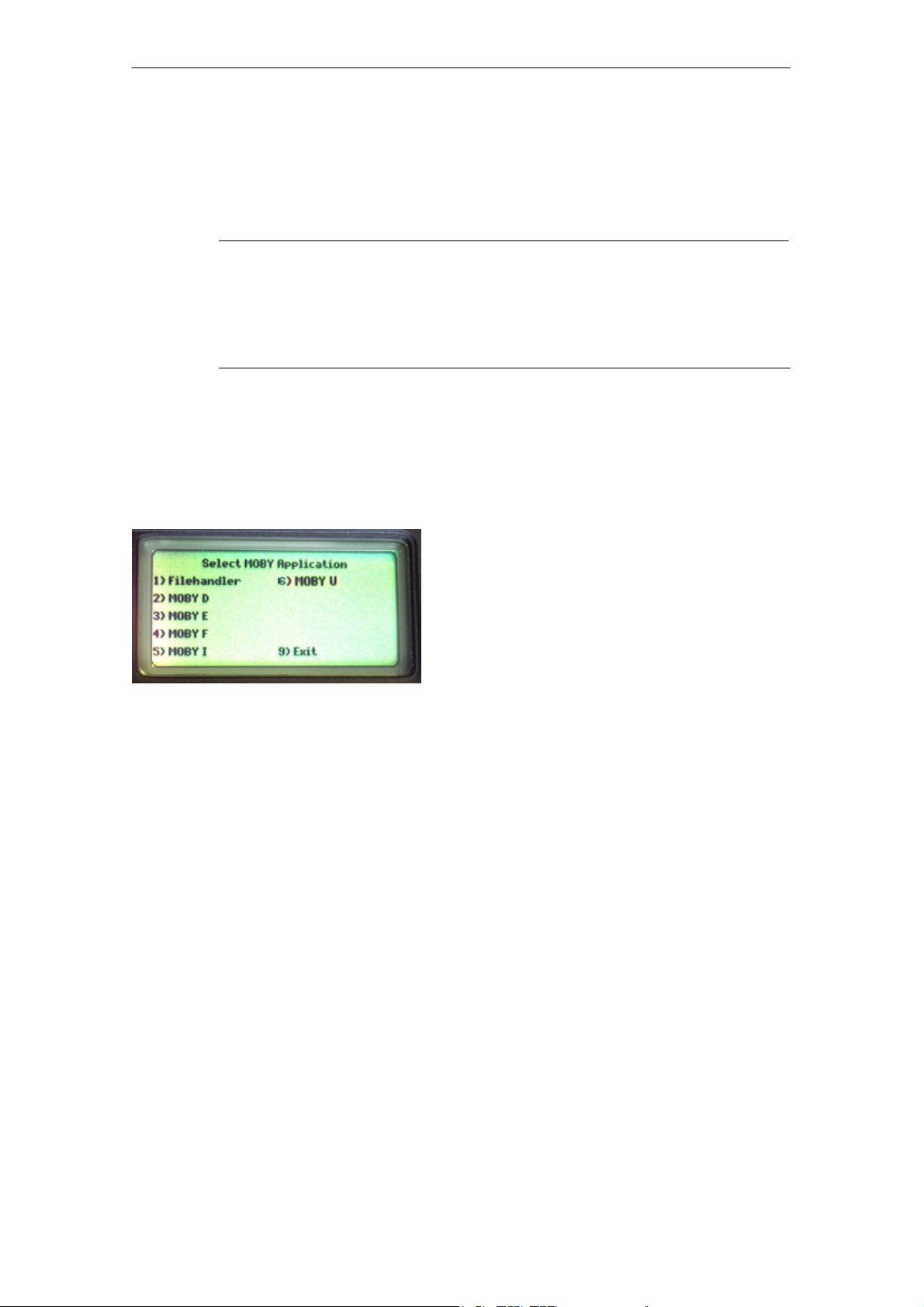
After the terminal is turned on, initial startup takes several seconds. The MOBY
application then starts automatically, and a selection menu appears with the
MOBY applications. Select the MOBY application for the RF read/write head or
the antenna which you want to use.
1) MOBY filehandler for MOBY I
The MDS data are accessed by file
names. See chapter 5.
2)-6)Normal MOBY service and test program for MOBY D/E/F/I/U. The MDS
data are accessed by physical addresses. See chapter 4.
9) The operating system of the hand-held
terminal is accessed with “Exit.”
V) Version indication in MOBY application
menu (not shown in selection menu)
The device goes off automatically after no keys have been pressed for 5 minutes. When turned on again, the hand-held terminal continues with the same
screen it was displaying before it was turned off manually or automatically.
See chapter 6.5.
E-6
STG Hand-Held Terminal
(5)J31069-D0126-U001-A5.1-7418
Page 13

R 01.04
Commissioning the STG
2.4 MOBY Applications
If you use a different read head (MOBY D/E/F/I) or the MOBY U antenna with
the hand-held terminal later on, you will have to change the MOBY application.
Exit the running application with the FILE/EXIT menu. The PSION start screen
appears. Confirm this screen with ENTER. Then select the required MOBY
application in the next screen which appears.
2.5 User Interface
Use of the STG programs MOBY D/E/F/I/U on the hand-held terminal is
described in chapter 4.
Use of the Filehandler program for MOBY I is described in chapter 5.
All functions of the MOBY programs can be called with the “Menu” key.
STG Hand-Held Terminal
(5)J31069-D0126-U001-A5.1-7418
E-7
Page 14
Using the STG
3 Using the STG
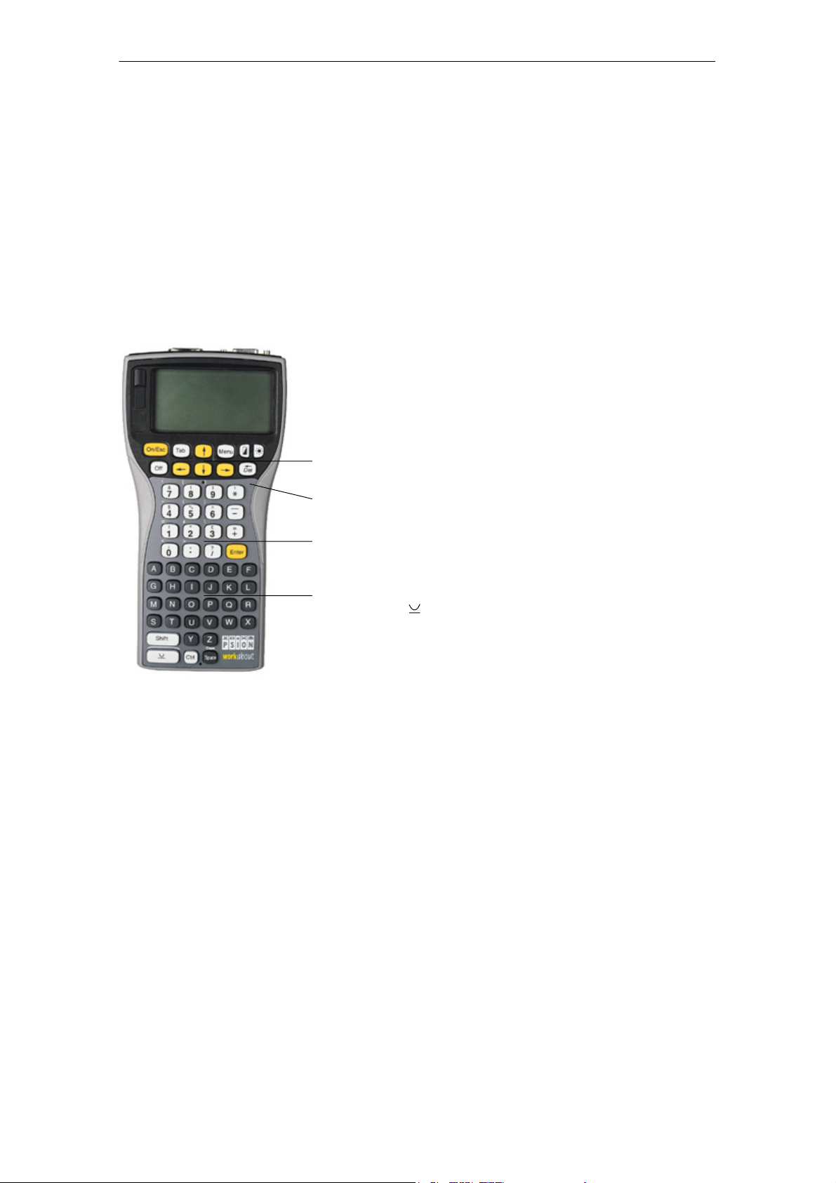
3.1 Keyboard
The keyboard of the PSION is divided into 3 parts.
S 11 control keys directly below the display
S Numerical key block with 16 keys
S ASCII keyboard (30 keys) including shift key
Control keys: Contrast, display illumination,
on/off, and cursor keys
R 01.04
Green LED. Goes on when battery is being
charged.
Numeric input block with Enter key
ASCII keyboard plus shift and special function
keys (Ctrl, )
E-8
STG Hand-Held Terminal
(5)J31069-D0126-U001-A5.1-7418
Page 15
R 01.04
Using the STG
3.2 Antenna on the Read Head and Antenna Field
3.2.1 MOBY D/E/F/I
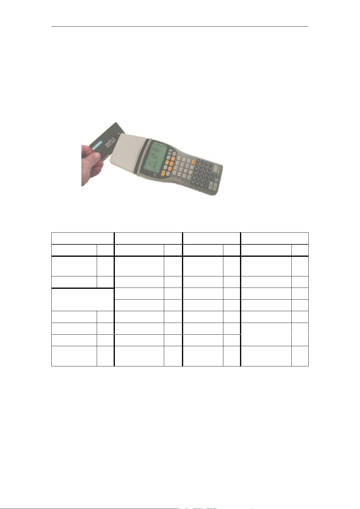
The antenna of the read head is located on the top of the hand-held terminal as
shown in the figure below.
Reading an MDS
The various types of MDSs offer different ranges. The following table gives you
an overview.
MOBY D MOBY E MOBY F MOBY I
MDS Type mm MDS Type mm MDS Type mm MDS Type mm
D139 60 E600
18 F125 80 402/401 6
(ISO card)
D160 25 E611 30 F415 50 404/514/413E 20
Labels based on
Basis I-Code:
E624 (button) 8 F124 60 403 8
3
E623 (pill)
1
4/3
2
506 12
I-Code1 75 439E 12
I-Code SLI 100 507
Tag-it HF-I 100
(with battery)
my-d 100 507 (without
35
4
battery)
1 The pill can only be read on the head portion provided for this.
2 When MDS is installed in metal
3 Range tolerances are to be expected for manufacturing reasons. The distances apply
to labels with the size 85 x 55 mm.
STG Hand-Held Terminal
(5)J31069-D0126-U001-A5.1-7418
E-9
Page 16

Using the STG
R 01.04
MOBY E/I
Example:
MDS E623
Example:
MDS E600
MOBY D/E/F
Button antenna or
rod antenna (MOBY I)
Surface
antenna
The antenna field for the STG read head
Antenna field for MOBY E
With the MOBY E read head, 2 antennas are integrated in the reader. These
must be positioned on the read head based on which MDS you want to read.
The EXTRAS/ANTENNE command (see chapter 4.5.3) is used to switch the
antenna field. Remember that the MDS E623 can only be read on the antenna
provided for this. See figure. The MDS E624 can be read on both the button
antenna and the surface antenna.
E-10
STG Hand-Held Terminal
(5)J31069-D0126-U001-A5.1-7418
Page 17
R 01.04
Using the STG
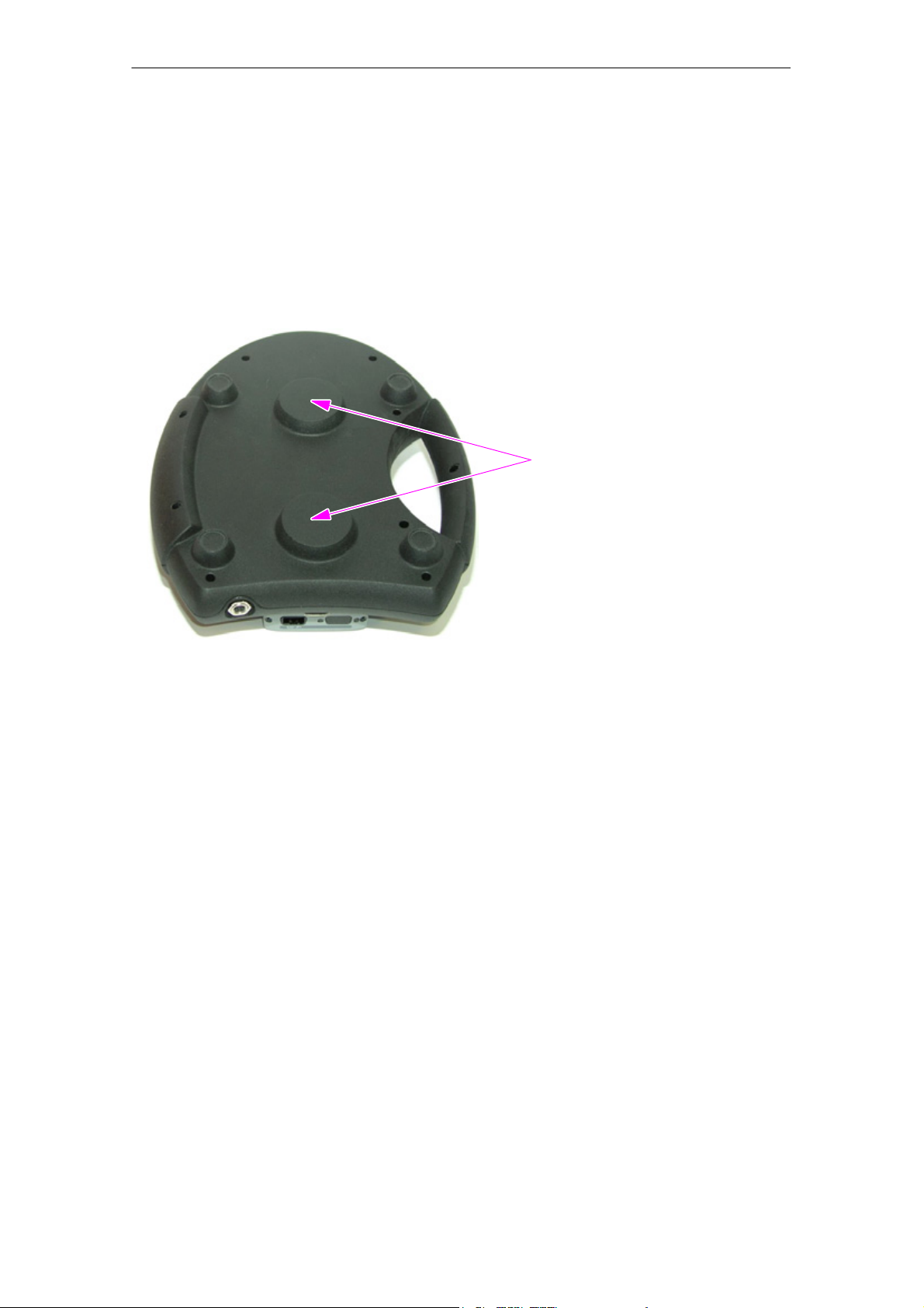
3.2.2 MOBY U
The actual antenna of the STG U hand-held terminal is located on the back of
the MOBY U antenna (see photo below). This means that the direction of emission is vertical to the back of the MOBY U antenna. The cone-shaped antenna
field has an opening angle of approx. 90 degrees. The maximum field length
(limit distance) is 3 meters. It can be set in increments of 0.5 m in the “Extras”
menu.
Antenna
Back of the MOBY U antenna
STG Hand-Held Terminal
(5)J31069-D0126-U001-A5.1-7418
E-11
Page 18
Using the STG
R 01.04
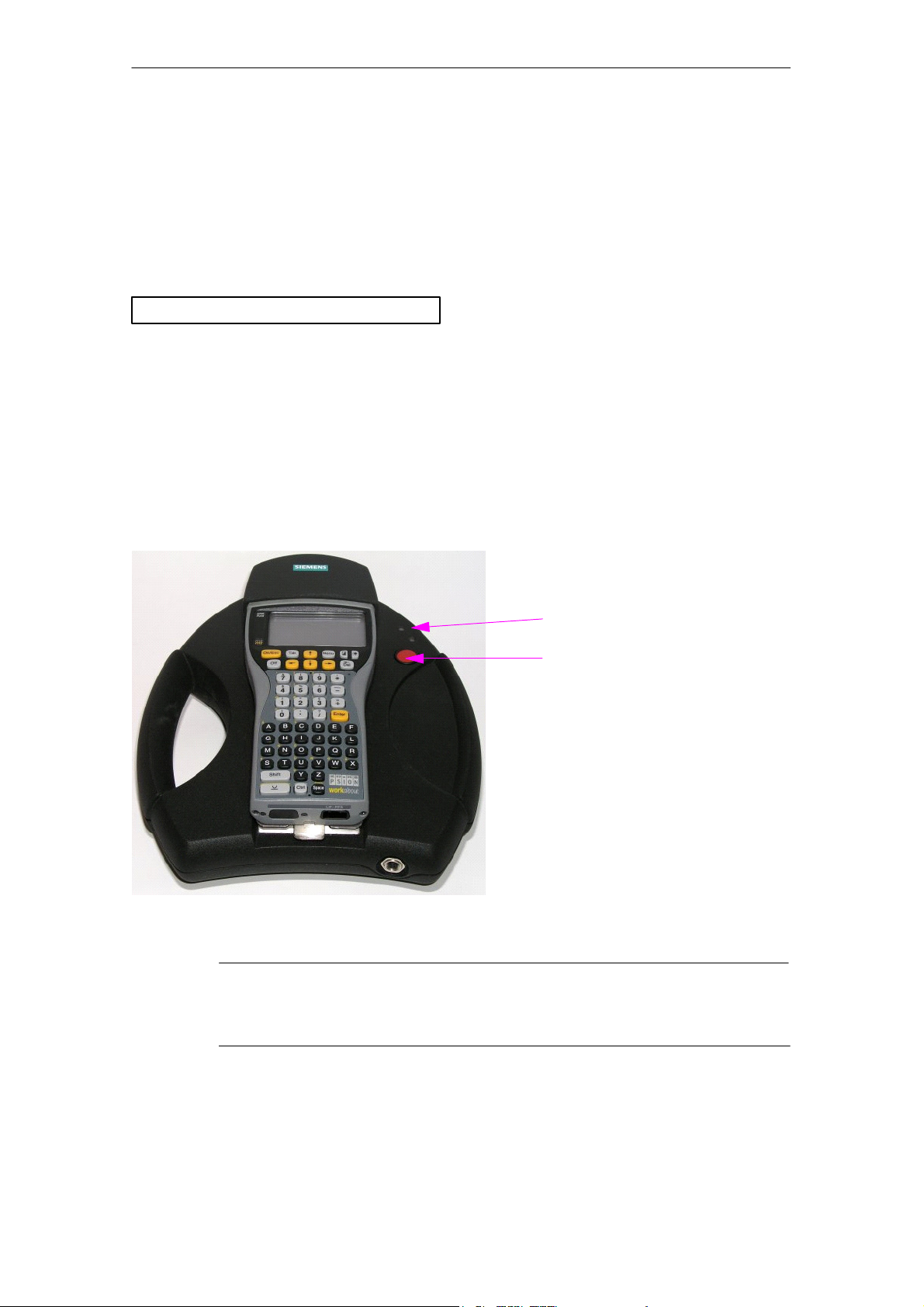
3.3 Using the MOBY U Antenna
The MDS functions (e.g., read, write, initialize) are not triggered on the STG U
hand-held terminal until the communication button is pressed.
The “Menu” button is used to select the appropriate MDS function. The following message appears on the display.
Wait for ENTER of antenna
ESC to cancel
Then point the STG U hand-held terminal to the desired MDS Uxxx and press
the communication button.
After the communication button is pressed, the antenna goes on, the MDS
function is executed, and the antenna goes off again. As long as the antenna is
active, the LED for communication is yellow. It takes approx. 2 seconds to turn
on the antenna. Depending on the amount of data and the recognition of the
MDS, turn on takes a minimum of approx. 3 seconds.
LED for communication
Communication button
STG U hand-held terminal
Note
The LED communication lights up red when the charging status of
the batteries is not sufficient for communication.
E-12
STG Hand-Held Terminal
(5)J31069-D0126-U001-A5.1-7418
Page 19

R 01.04
Using the STG
3.4 Charging Function
The battery charging procedure is started as soon as the PSION Workabout is
placed in the wall or vehicle holder. Charging is activated and indicated with a
green LED. See chapter 3.1.
When the batteries are empty, at least 14 hours are required for a complete
charge.
High-speed battery charging
The batteries supplied by Siemens for the PSION Workabout can be charged at
high speed so that the MOBY hand-held terminal can be operated directly in
the high-speed charging device available from PSION. A full charge takes
1 hour.
Use of other batteries
Other AA batteries can also be used in the PSION Workabout. These include
rechargeable NiCd batteries and alkali batteries which cannot be recharged.
IMPORTANT: Be sure to adhere to the PSION user’s manual.
The backup battery
The backup battery in the PSION Workabout is used to retain the application
data when the main batteries are empty. The backup battery is a lithium cell
which cannot be charged. Remember that, when the main batteries are empty
or have been removed, a new backup battery can only maintain the data in the
RAM for just a few days.
STG Hand-Held Terminal
(5)J31069-D0126-U001-A5.1-7418
E-13
Page 20
Using the STG
R 01.04
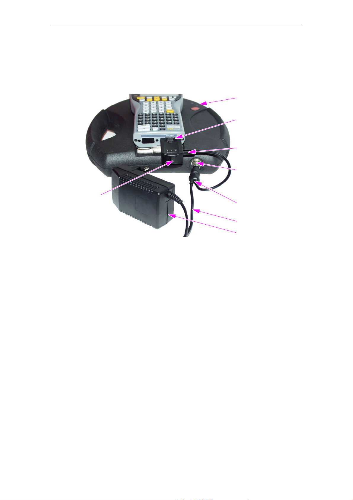
Charging STG U hand-held terminal
The batteries of the STG U hand-held terminal (in the PSION Workabout and
the MOBY U antenna) can be charged with only one power pack
(6GT2 503-1DA00).
LED for charging
the batteries
Charging socket
of the PSION
Workabout
Plug for the
charging adapter
Charging socket
of the MOBY U
antenna
Charging adapter
for the PSION
Cable switch on
the charging cable
Workabout
Charging cable
Power pack
The STG U hand-held terminal with connected power pack for charging
the batteries
Proceed as shown below to connect the power pack to charge the batteries.
S Plug charging adapter into the charging socket of the PSION Workabout.
S Plug connector on the cable switch of the charging cable into the charging
socket of the MOBY U antenna.
S Plug connector for charging adapter on the charging cable into the charging
adapter.
S Connect power plug of the power pack.
The charging status of the battery pack of the MOBY U antenna is indicated by
the LED for charging the batteries.
S Yellow: The battery pack of the MOBY antenna is being charged.
S Green: The battery pack of the MOBY antenna is charged.
S Red: The device is defective.
On the PSION Workabout, a green LED (see chap. 3.1) is on during charging.
STG Hand-Held Terminal
E-14
(5)J31069-D0126-U001-A5.1-7418
Page 21

R 01.04
When batteries are empty, duration of charging is:
S At least 1.5 hours for the MOBY U antenna
S At least 14 hours for the PSION Workabout.
The STG U hand-held terminal can also be used during charging.
Note
S The PSION Workabout can only be charged when it is equipped
with original PSION batteries.
S A restricted temperature range must be adhered to when the bat-
tery pack of the MOBY U antenna is being charged:
0 °C to +40 °C.
Using the STG
STG Hand-Held Terminal
(5)J31069-D0126-U001-A5.1-7418
E-15
Page 22

Using the STG
R 01.04
3.5 Changing the Battery Pack of the MOBY U
Antenna
The battery of the MOBY U antenna is a lithium ion battery pack. It has a lifespan of approx. 500 charging cycles.
When the capacity of the battery pack has decreased to the point that the operating time of the MOBY U antenna is no longer sufficient for the application, it
is time to replace the battery pack.
Disconnect the 9 screws on the back of the housing shell of the antenna and
remove the shell. Replace the battery pack. Replace the housing shell and
screw it tight.
Note
S The power pack may not be connected on the STG U hand-held
terminal while the battery pack is being replaced.
S The PSION Workabout does not need to be separated from the
MOBY U antenna although it must be turned off during replacement.
Note
The replacement battery pack for the MOBY U antenna has the
order number 6GT2 594-0AB00.
Warnung
!
The battery pack of the MOBY U antenna and the replacement
battery pack consist of lithium ion batteries. The following must be
adhered to when handling these batteries.
S Avoid risk of fire, explosion and severe burns.
S Do not expose the battery pack to temperatures in excess of
100 °C.
S Do not take the battery pack apart or destroy it.
Incorrect handling, damage or contact with water may cause the
battery pack to explode.
E-16
S Adhere to national regulations when disposing of used recharge-
able batteries/batteries.
STG Hand-Held Terminal
(5)J31069-D0126-U001-A5.1-7418
Page 23

R 01.04
The “MOBY D/E/F/I/U” Programs
4 The “MOBY D/E/F/I/U” Programs
After you turn on the STG, the editor appears on the display. You can view the
data, enter new data or call a function with the “Menu” key. Functions can also
be called directly with the key. To do this, press the key and the appropriate alphanumeric key at the same time. The table below lists all functions together with their direct calls.
Command Shortcut Description
File/Load File L or F3
File/Save S or F4
File/Exit X Exit STG application
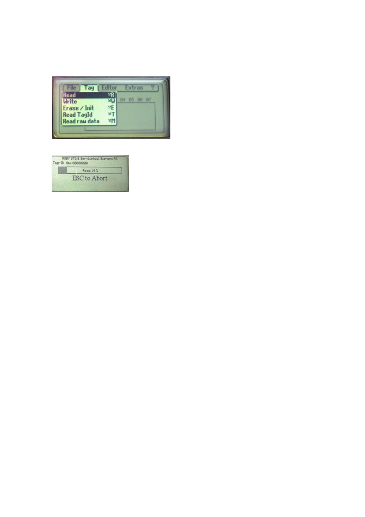
Tag/Read R or F1
Tag/Write W or F2
1
Load file from PSION RAM drive to working storage
1
1
1
Store read MDS data on the RAM drive
Read data from MDS
Write data to MDS
Tag/Erase/initialize E Write MDS with a certain value
Tag/Tag status O
3
Read MDS status
Tag/Read TagId T Read ID number of MDS
Tag/Read OTP F
Tag/Write OTP H
Tag/Read raw data M
3
3
2
Read data from OTP memory
Write data to OTP memory
Read physical memory of MDS
Editor/Jump to address J or Tab Jump to a certain address in editor
Editor/Display D Change display options
Editor/Clear C Clear data in editor to a certain value
Editor/edit date A The date on which the cursor is posi-
tioned can be edited in a number of for-
mats.
Extras/Communication I Change communication options
Extras/Password for STG P Change password for STG application
Extras/Address Setup G Define entries for the “read/write MDS”
commands
Extras/MOBY I Setup H Set memory size and MOBY I operating
mode
STG Hand-Held Terminal
(5)J31069-D0126-U001-A5.1-7418
E-17
Page 24

The “MOBY D/E/F/I/U” Programs
R 01.04
Command DescriptionShortcut
Extras/MOBY E Setup Y Switch MDS access from “MOBY key” (A)
to the B key
For MOBY E SIM: Switch between cyclic
operation and continuous operation
Extras/MOBY U Setup K
Extras/SLG status Q
?/Language N Set menu language
?/About... B Manufacturer’s data
?/Version V Version of operating system and STG
1 These keys are only available on a hand-held terminal with a numeric keyboard.
2 Not MOBY U
3 Only MOBY U
3
3
Define MDS memory size and range limit
Read status of MOBY U antenna
application
E-18
STG Hand-Held Terminal
(5)J31069-D0126-U001-A5.1-7418
Page 25
R 01.04
The “MOBY D/E/F/I/U” Programs
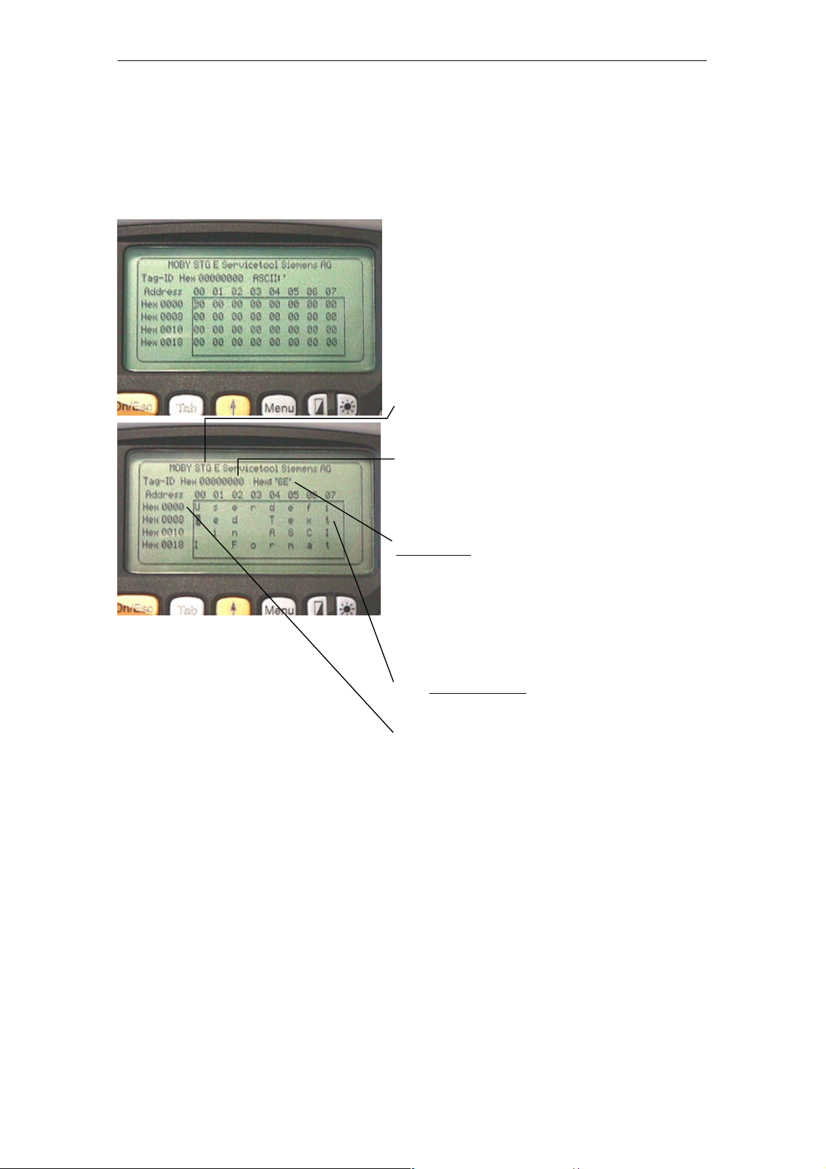
4.1 Data Editor
The MDS data can be edited in hexadecimal or ASCII in the editor screen. This
can be set in the EDITOR/DISPLAY menu.
The editor always shows the total size of
an MDS memory. Use the cursor functions to access the individual addresses.
Use the “Tab” key to jump to any address. See chapter 4.4.1.
Indication of the currently set read head.
Cf. chapter 4.5.1
The TagId of the MDS is only displayed
on the MOBY E/F/D/U. It is valid after
the “MDS/read-write-readTagId” function
is executed.
Date field:
The date on which the cursor is located
can also be shown in hexadecimal,
decimal, ASCII or binary format. The
“Editor/edit date” function can be used to
change the value in the date field.
The editor screen contains the MDS date.
Standard setting is 32 bytes.
MDS addresses are shown in hexadecimal or decimal format.
STG Hand-Held Terminal
(5)J31069-D0126-U001-A5.1-7418
E-19
Page 26
The “MOBY D/E/F/I/U” Programs
R 01.04
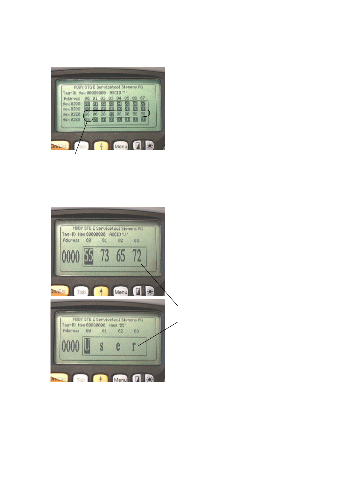
The “current area”
The editor uses normal representation
for the “current area.” All other data
areas of the MDS are shown inverted.
The current area shows the data block
which was read last. During read/writeaccesses, the current area is entered as
the value for the write command.
This value can be adjusted in the
TAG/WRITE or TAG/READ menu.
Current area
The current area is changed automatically when you edit data and overwrite.
The size of the memory area shown on the display can be switched
with the EDITOR/DISPLAY function. See chapter 4.4.2.
In the normal representation, 32 bytes
are displayed in lower case letters. This
gives you an overview of the MDS data.
In zoom representation, only 4 consecutive bytes are shown. Representation is
in upper case letters. This display is
easy to read.
Zoom representation (hexadezimal)
Zoom representation (ASCII)
E-20
STG Hand-Held Terminal
(5)J31069-D0126-U001-A5.1-7418
Page 27
R 01.04
4.2 MDS Functions
The “MOBY D/E/F/I/U” Programs
The MDS functions handle communication with the MDS.
The MDS function is not interrupted if
you briefly move the MDS out of the
read field. The MDS function is terminated if MDS processing does not take
place for more than 30 seconds. See
chapter 4.5.
After a command is started, a window
with a bar appears on the display. This
bar shows how much of the command
has already been processed.
4.2.1 General Information on Read and Write-Accessing
an MDS
The MOBY D, MOBY E and MOBY F MDSs use block-oriented data accessing.
A read or write-access to an MDS is only possible at the beginning of a block.
One block contains 16 bytes (or 10 hex) with MOBY E/F. Thus, the start
addresses for MDS processing to be entered on the STG are:
00, 10, 20, 30 hex and so on.
With MOBY D a block has a length of 4 bytes (I-Code, Tag-it) or 8 bytes (my-d).
The start addresses are:
00, 04, 08, 12 hex ... (I-Code, Tag-it) or
00, 08, 10, 18 hex ... (my-d).
With the MOBY D/E/F/U, the TagId on the display is automatically updated to
the current value after the read/write access.
STG Hand-Held Terminal
(5)J31069-D0126-U001-A5.1-7418
E-21
Page 28

The “MOBY D/E/F/I/U” Programs
However, you can also specify any start address.
This will be accepted by the STG and corrected to
the next lower block beginning. The corrected address is indicated for the operator in a window and
must be acknowledged.
An additional window appears if you change data in
the editor and then attempt to read an MDS. The
window tells you that the data which you have just
modified may be overwritten again with the “read
MDS” command. You can retain or reject the modified data in the editor, or you can terminate the command completely.
Note
ECC mode can only be set on the MOBY I hand-held terminal.
R 01.04
ECC mode cannot be used with MOBY D/E/F/U.
4.2.2 Reading the MDS
A data block with a start and end address, which can be defined as desired,
can be read from the MDS. If the same value is entered for the start and end
address, only one block can be read from the MDS. The address area is indicated in another screen for confirmation.
Note
If mode “Complete MDS” was selected in the read/write field of the
menu “Extras/Address Setup/...,” the “MDS/read” funktion is started
immediately without asking any questions. The complete MDS is always processed.
E-22
STG Hand-Held Terminal
(5)J31069-D0126-U001-A5.1-7418
Page 29

R 01.04
The “MOBY D/E/F/I/U” Programs
4.2.3 Writing the MDS
A data block can be written to the MDS. The data block which is valid in the
editor is indicated as the default for each write access. The default length or
end address can still be changed to another value during the write-access.
4.2.4 Erasing/Initializing the MDS
The “erase/initialize MDS” function is used to write the entire MDS with a
certain value in a very short time. The erasure value can be entered in a
subsequent menu. After the deletion function has been performed, the memory
in the editor is also erased with the value which was entered. With the
MOBY I/U, the correct size of the MDS memory must be set (Extras/MOBY I
Setup or Extras/MOBY U Setup) before this function is performed.
STG Hand-Held Terminal
(5)J31069-D0126-U001-A5.1-7418
E-23
Page 30

The “MOBY D/E/F/I/U” Programs
R 01.04
4.2.5 Reading MDS Status
Only MOBY U: The function reads the status data from the MDS and indicates
it.
MDS status information
S MDS number (8-position, hexadecimal format) and MDS memory size (2 or
32 kB)
S Data for calculation of the battery lifespan (total accesses, total search, and
change sleep time)
S Remaining battery life time of the MDS in %
S Sleep time set on MDS
Note
For calculation of the battery lifespan of the MOBY U data medium,
it is essential that the STG software have the current calendar week
and the current calendar year. This is the reason the date must be
set correctly on the PSION Workabout.
The date can be set via the system menu “Time” → “Time and date.”
Proceed as shown below.
S Exit the MOBY U service and test program via “File/Exit.”
S Select “System screen.”
S Position the cursor on the application “IMG.”
S Click the “Menu” button.
S Select “CTRL/Set time and date.”
S Set “Time” and “Date” and accept with “Enter” button.
S Return to the MOBY U service and test program via “IMG” and
“Moby_u[A].”
E-24
STG Hand-Held Terminal
(5)J31069-D0126-U001-A5.1-7418
Page 31

R 01.04
The “MOBY D/E/F/I/U” Programs
4.2.6 Reading the ID Number
Only MOBY D/E/F/U: The function reads and indicates the serial number of the
MDS. The ID number is set at the factory and cannot be changed.
The TagId is displayed in hexadecimal format by the editor in the second line.
The TagId is automatically read with the “MDS read/write/erase” functions.
4.2.7 Reading OTP Memory
Only MOBY U: The function reads the complete OTP memory (16 bytes).
Note
When the mode “MDS complete” was selected in the “Read/write”
field in the “Extras/Addresses Setup/...” menu, the function “MDS/
Read” is started immediately without any further questions. The
entire MDS is always processed.
4.2.8 Writing OTP memory
Only MOBY U: The function writes the complete OTP memory (16 bytes).
Note
The OTP memory can be written only once. Before execution, you
are asked again whether you really want to execute the function
since this action is irreversible.
STG Hand-Held Terminal
(5)J31069-D0126-U001-A5.1-7418
E-25
Page 32

The “MOBY D/E/F/I/U” Programs
R 01.04
4.2.9 Reading Raw Data
Only MOBY D/E/F: This function is used to physically read the entire memory of
the MDS. This includes TagId, key information (if public), manufacturer’s
information and MDS access rights. A knowledge of the physical layout of the
MDS memory is required to interpret the data. See description of MFWAPI or
CCTWAPI.
The “read raw data” function can be used to detect errors made when the MDS
was configured.
Note
For MOBY F
MDS addresses 8 to 3F hex (i.e., pages 2 to 15) cannot be read.
They are always shown by the editor as 00.
E-26
STG Hand-Held Terminal
(5)J31069-D0126-U001-A5.1-7418
Page 33

R 01.04
4.3 File Functions
4.3.1 Loading a File
The “MOBY D/E/F/I/U” Programs
A file can be loaded to the STG editor which was
S saved before with the “file/save” command or
S transferred from the PC to the “RAMDRIVE (M:)” drive of the PSION. See
chapter 6.2.
4.3.2 Saving
Data currently being displayed by the editor can be saved in a file on the
PSION. The file name may consist of 1 to 8 letters or numbers. During the
storage procedure, the extension “.HEX” (data) and “.HX1” (ID no.) is
automatically added to the file name. See also chapter 6.2.
A memory area of approximately 1.8 Mbytes is available on the hand-held
terminal for storage of MDS data (i.e., with MOBY E, up to 2000 MDSs can be
read and stored).
4.3.3 Exiting
The “exit” function can be used to conclude the STG program of MOBY. This
gives you access to the operating system levels of the PSION hand-held
terminal. See chapter 6.3.
STG Hand-Held Terminal
(5)J31069-D0126-U001-A5.1-7418
E-27
Page 34

The “MOBY D/E/F/I/U” Programs
4.4 The Editor Functions
4.4.1 Jump to Address
You can enter a memory address in decimal or hexadecimal format. The
setting can be changed under menu item Display/Display Address. This
address will then be represented by the editor as the start address.
R 01.04
This function can also be triggered directly in the editor with the “Tab” key.
4.4.2 Display
The following settings are available in this menu.
S Switch the editor between 32-byte representation (i.e., 4x8= fine-print
display) and 4-byte representation (i.e., 1x4= large, easy-to-read
characters).
S No address is displayed for editor representation 1x5. This display is very
good when reading fixed-code MDSs with the MOBY F. With other MDS
types, the first 5 bytes of the read data are displayed. You cannot change to
other addresses with the cursor.
S Switch the editor between hexadecimal and ASCII representation. The
addresses are always shown in hexadecimal or decimal format.
S Switch date between “BIN,” “ASCII,” “DEC” and “HEX” format.
E-28
STG Hand-Held Terminal
(5)J31069-D0126-U001-A5.1-7418
Page 35

R 01.04
The “MOBY D/E/F/I/U” Programs
4.4.3 Clear Display
The “clear display” function is used to overwrite the entire memory in the STG
editor with a value which you can specify. You can then change the desired
data to the appropriate values in the editor. No function is performed on the
MDS.
S The data field can be shown in hexadecimal, ASCII, decimal or binary for-
mat. The data can also be changed with the “Indicate/edit date” function with
the format set here.
S The addresses can be indicated in hexadecimal or decimal.
4.4.4 Edit Date
In addition to the standard formats hex and ASCII of the editor screen, the “edit
date” function also provides the decimal and binary formats for data entry.
STG Hand-Held Terminal
(5)J31069-D0126-U001-A5.1-7418
E-29
Page 36

The “MOBY D/E/F/I/U” Programs
R 01.04
4.5 The Extras Functions
4.5.1 Communication
S Interface Switching between the TTL interface (read head) and the
RS 232 interface takes place here.
If the RS 232 setting is used, the protocol must be set to
“MOBY E/SIM” or “ASM 420/I/V.”
No setting is required for MOBY U. The interface is
permanently set to RS 232.
S Protocol Certain protocols can be set here depending on which read
head is being used.
Read Head Protocol That Can Be Set
MOBY D
MOBY E
MOBY I
When the MOBY protocol is set, the memory size of the editor
is also automatically specified for MOBY E/F.
With MOBY I, the memory size of the editor is set with the
“Extras/MOBY I Setup” function.
The 3964R protocol is permanently set for MOBY U. The
memory size of the editor is set with the “Extras/MOBY U
Setup” function.
MOBY D
MOBY D ISO
MOBY E
MOBY E/SIM
MOBY I
ASM 420/I/V
E-30
STG Hand-Held Terminal
(5)J31069-D0126-U001-A5.1-7418
Page 37

R 01.04
The “MOBY D/E/F/I/U” Programs
4.5.2 Password
A password can be programmed as an option. The password must be entered
prior to a write-access function. Once entered, a password remains valid until
the STG is turned off (i.e., the password only has to be entered once during
several consecutive write commands). The “MOBY” program can also only be
exited with the password.
Default password
On delivery, the password is “123.” This password is also set after you remove
the batteries of the STG.
Forgot the password?
If a password is forgotten, there is no way to obtain it again. The only solution
is to remove the main battery and the button cell from the PSION for a few
minutes. After the batteries have been re-installed and the device has been
turned on, the STG assumes its status on delivery (i.e., the password is “123”).
Password 99999999
Changing the password to 99999999 (i.e., eight 9s) has a special purpose.
The write-access function to the MDS and the “file/exit” function can no longer
be executed. The password can also no longer be changed. The only way to
access the write-access function again is to remove all batteries. See also
“forgot the password?”.
4.5.3 Antenna
Only for MOBY E: The antenna field on the read head is switched between
“card” (large antenna) and “button” (small antenna). See also chapter 3.2.1.
The antenna must be set once when the read head is commissioned. The
set antenna is retained on the read head when the hand-held terminal is
turned off.
STG Hand-Held Terminal
(5)J31069-D0126-U001-A5.1-7418
E-31
Page 38

The “MOBY D/E/F/I/U” Programs
R 01.04
4.5.4 Address Setup
This function defines the call of the “read/write MDS” commands.
S Start address + Length: Entry of the MDS address for the read/
write command uses a start address
and the length of the data to be
processed.
End address: Entry of the MDS address for the read/
write command uses a start address
and an end address.
S Read/Write Switching from “block” to “complete MDS” takes place
here. This setting affects the default setting for
execution of an MDS command.
Block: When an MDS is read/written, the
currently active area is always indicated
as the area to be read/written.
Complete MDS: When an MDS is read/written, the
entire MDS is always processed.
The read/write function is started
immediately. Partial MDS areas cannot
be entered.
E-32
STG Hand-Held Terminal
(5)J31069-D0126-U001-A5.1-7418
Page 39

R 01.04
The “MOBY D/E/F/I/U” Programs
4.5.5 MOBY I Setup
S Mem size: Specifies the memory size of the MDS to be processed
This setting also defines the memory area in the editor.
MDS memory addresses which exceed the memory size
cannot be addressed.
S Tag type: Distinguishes between RAM/FRAM and EEPROM
The RAM/FRAM setting shows an empty MDS support
battery on the STG.
S ECC: Turns the ECC driver on and off
The purpose of the ECC driver is described in the
documentation of the MOBY interface.
S MDS507: This parameter must only be set to “yes” when the
MDS 507 is used. With the MDS 507, the dialog battery
is scanned and indicated as “Status” when it is empty.
S Sample rate: The scan time is only relevant when the MDS 507 is
used with an ASM 420. The setting range is 0.1 sec to
6.3 sec. The default value (0.5 sec) usually does not
have to be changed.
4.5.6 MOBY E Setup
S Key A/B: You can switch between the “MOBY key” and the
“B transport key for MIFARE data memory.”
The MOBY key is always standard. The “B” setting
permits the MIFARE MDS to be processed in its status
on delivery. (The B key must be in its original state.)
S Mode: Only for MOBY E SIM (cf. chapter 6.6):
Switches the SIM from cyclic mode to continuous mode.
Command processing is much faster in continuous
mode.
S Antenna: You can switch between card and pill.
STG Hand-Held Terminal
(5)J31069-D0126-U001-A5.1-7418
E-33
Page 40

The “MOBY D/E/F/I/U” Programs
R 01.04
4.5.7 MOBY U Setup
S Memory size: Specify memory size of the MDS to be processed. This
setting can also be used to specify the memory area in
the editor. MDS memory addresses beyond the memory
size cannot be accessed.
S Standby time: The standby time can be set in increments of 7 msec
from 0 msec to 1400 msec. The default value (OFF)
usually does not have to be changed.
S Working range The field length (limit distance) is 3 m. It can be set in
limitation: increments of 0.5 m to avoid excess working ranges for
the antenna.
The setting range is between 0.5 m and 3.5 m. The
default value is 1 m.
4.5.8 SLG Status
Only MOBY U: The SLG Status function can be used to read version states and
settings of the MOBY U antenna.
The information can be accessed with the “Enter” key in 3 consecutive screens.
S Screen 1: Hardware, firmware and loader version
S Screen 2: Driver model, driver version and interface parameters
S Screen 3: Set working range limitation, standby time and multitagging
(equals 1)
E-34
STG Hand-Held Terminal
(5)J31069-D0126-U001-A5.1-7418
Page 41

R 01.04
4.6 The “?” Functions
4.6.1 Language
The “MOBY D/E/F/I/U” Programs
German or English can be selected as the menu language with the STG.
During commissioning of the STG, the default language is English.
4.6.2 About
Information on the manufacturer of the STG program:
Siemens AG A&D PT7 M2
4.6.3 Version
Specifies the version of the STG program, the EPOC operating system, the
release status of the ROM version and the release status of the MOBY library.
These parameters must be specified when reporting errors to Siemens.
STG Hand-Held Terminal
(5)J31069-D0126-U001-A5.1-7418
E-35
Page 42

The “FILEHANDLER” Program
R 01.04
5 The “FILEHANDLER” Program
5.1 General Information on the Filehandler
As with any PC-based system, the filehandler accesses the data with logical file
names and not with physical memory addresses.
The following figure shows the layout of the “FILEHANDLER” program and how
it works.
Files on hand-held terminal
File 3.hex
File 2.hex
File 1.hex
Directory
display
Files on MDS
File 3
File 2
File 1
Editor
display
Optional connection on the PC
WORD
EXCEL
.
.
MOBY\File 3.hex
MOBY\File 2.hex
MOBY\File 1.hex
The “FILEHANDLER” program is designed so that you can use the same functions to access the files on the hand-held terminal and the files on the MDS.
The directory display is available for both the hand-held terminal and the MDS.
MDS files can be copied from the MDS to the hand-held terminal (and vice
versa) with just a few keys.
An optional connection to the PC (3link cable, see appendix A.1) permits you to
exchange files stored on the hand-held terminal with the PC.
You can then process the data with your familiar PC programs (e.g., WORD,
EXCEL, and so on). Prerequisite: The PC application must support the contents and data structure of the MDS file. See also chapter 6.
STG Hand-Held Terminal
E-36
(5)J31069-D0126-U001-A5.1-7418
Page 43

R 01.04
The “FILEHANDLER” Program
Note
Remember that the filehandler is only available for the MOBY I.
5.2 The Filehandler Commands
STG Command Shortcut
1
Filehandler
Description
Command
File/Read File from
Ta g
File/Read File from
STG RAM
File/Write File to Tag W or F2
File/Write File to STG
RAM
R or F12, or
Enter
S or F3
T or F4
2
2
2
READ Read a file from the MDS
– Read a file from the RAM of
the hand-held terminal
WRITE Write a file to the MDS
– Write the data from the editor
to the hand-held terminal
File/Read Dir from Tag G DIR Read directory from the MDS
and indicate
File/rRad Dir from STG
RAM
P – Indicate directory of the STG
(RAM memory)
File/exit X – Exit filehandler application
Commands/Create
File
Commands/Delete File D or Del
Commands/Tag For-
B CREATE Create new file with length of
0 on the MDS
3
DELETE Delete file from the MDS
I FORMAT Format the MDS
mat
Commands/File Attrib-
ute
Y ATTRIB Assign access rights to file
on the MDS
Commands/Tag Status F MDS STATUS Read MDS status
Commands/Cover Tag C COVER Protect data structure of the
MDS
Editor/Display Direc-
Q – Display last read directory
tory
Editor/Display Editor U – Display file data
Editor/File Size N – Change file size in editor
STG Hand-Held Terminal
(5)J31069-D0126-U001-A5.1-7418
E-37
Page 44

The “FILEHANDLER” Program
R 01.04
STG Command DescriptionFilehandler
Editor/Clear Display J – Write display with certain
Editor/
Jump to address
Editor/Display Setup H – Switch display between
Extras/Parameter Z – Set filehandler parameters
Extras/Password for
FH
Extras/Communication E – Setting: Read head or ASM
?/Language L – Set menu language
?/About... K – Manufacturer’s data
?/Version V – Version of operating system
1 The key combination + key is used for the shortcuts of the commands. Both keys
must be pressed at the same time. The keys for the shortcuts of the MDS commands
are the same as the letters used to address them in the SIMATIC with FC.
2 Keys F1 to F4 are only available on a hand-held terminal with a numeric keyboard.
3 The
“Del” key can be used to delete the file currently selected in the directory view.
This can also be used to delete files from the RAM of the hand-held terminal.
Shortcut
O or Tab – Move cursor to address posi-
A – Password setting for the
1
Command
value
tion
ASCII and HEX representation
“FILEHANDLER” program
and filehandler
E-38
STG Hand-Held Terminal
(5)J31069-D0126-U001-A5.1-7418
Page 45

R 01.04
The “FILEHANDLER” Program
5.3 View of the Editor and Directory
The filehandler’s monitor screen display is either “Directory – View” or “Editor –
View.” You can use the menu “Editor/Display Editor” and “Editor/Display Directory” menu to switch between the two displays.
5.3.1 The Data Editor of the Filehandler
The design of the data editor of the filehandler is similar to the standard STG
program. See chapter 4.1.
Name of the file in the editor. The file
can have been read by both the MDS
and the hand-held terminal memory.
Set MDS memory size. It can be set
with the command Extras/Parameter.
The piece of data on which the cursor
is located. Is also shown in ASCII format.
The file length is shown here.
If the file size is too long (see
chap. 5.6.3), the extra data are
shown inverted.
The data area which is longer than
the file length is marked with the data
string
“eof” (end-of-file).
STG Hand-Held Terminal
(5)J31069-D0126-U001-A5.1-7418
E-39
Page 46

The “FILEHANDLER” Program
R 01.04
5.3.2 View of the Directory
The directory view shows either all files of the MDS or all files of the STG RAM.
The directory view makes it very easy to read files from the MDS or copy files
between hand-held terminal and MDS. See chapter 5.4.
Layout of the directory
Indication of whether the displayed directory is from an
“hand-held terminal”
Name with which the MDS was formatted. No name is indicated for the
hand-held terminal’s directory.
Free memory on the MDS. With the
hand-held terminal, this is approx.
1.8 MB (after the terminal has been
commissioned).
“MDS” or from the
A file can be selected with the cursor
keys. After selection, a function can
then be directly executed with this file.
See chapter 5.4.
An attribute can be entered here for
the MDS files (see chap. 5.5.4). No
attributes can be set for hand-held
terminal files.
E-40
STG Hand-Held Terminal
(5)J31069-D0126-U001-A5.1-7418
Page 47

R 01.04
The “FILEHANDLER” Program
5.4 The File Functions
The file menu primarily contains three functions which can be called.
S Read file
S Write file
S Read and display directory
These functions can be executed on both the MDS and the internal memory of
the hand-held terminal.
5.4.1 Read File from MDS (Read File from Tag)
After this function has been called, a menu appears in which you can select a
file with the cursor keys. All file names can be scrolled through, including the
ones in the directory view (see chap. 5.3.2).
After you have scrolled through all the files,
the file name “New Tag DIR” appears. If you
press the Enter key, the filehandler reads a
directory from an MDS.
You can then select one of the new files
If you continue paging through the file selection menu until the file name “Other File” appears, you can enter a file name (with the
ASCII keyboard of the hand-held terminal) in
the menu which appears.
STG Hand-Held Terminal
(5)J31069-D0126-U001-A5.1-7418
E-41
Page 48

The “FILEHANDLER” Program
R 01.04
5.4.2 Read File from STG RAM
After this function is called, a menu appears in which you can select a file with
the cursor keys. All file names in the RAM of the hand-held terminal with the
file extension .HEX are displayed. If the STG RAM does not contain any files
with the extension .HEX, the message “No file available” appears.
5.4.3 Write File to MDS (Write File to Tag)
The file name is entered as described in chapter 5.4.1. After a file name contained in the directory is entered, you are given the following choices.
You can overwrite the file or append the new
data to the existing file.
In the next screen, you can still change the
length of the data to be written.
The default length is always given as the
value of the length of the data in the editor. If
you change the default length, the data
length on the MDS will also be adjusted.
If you selected the “Append” data option, the file is automatically read again after execution of the write function. This gives you the complete updated file on
the editor.
If you selected the file name “Other File” when you called the write function and
entered a new file name with the keyboard, the “Create” screen appears.
If you confirm this screen with “Yes,” a new
file is created on the MDS before the data are
written to the MDS.
E-42
STG Hand-Held Terminal
(5)J31069-D0126-U001-A5.1-7418
Page 49

R 01.04
The “FILEHANDLER” Program
5.4.4 Write File to STG RAM
When a file is saved, the file name indicated in the editor is also indicated as
the default name. You can still change the file name before saving the file. The
file name may contain up to 8 characters. When the file is saved, the file extension .HEX is automatically added to the file name.
5.4.5 Read Directory from MDS (Read Dir from Tag)
The file directory of an MDS is read and indicated on the display in the directory
view (see chap. 5.3.2). With some MDS types, this may take several seconds.
5.4.6 Read Directory from STG RAM (Read Dir from STG
RAM)
The file directory of the hand-held terminal’s RAM (drive M:) is read and indicated on the display in the directory view (see chap. 5.3.2). Only type *.HEX
files are shown on the display. Also, only files located in the root directory of
the hand-held terminal’s RAM are indicated on the display.
STG Hand-Held Terminal
(5)J31069-D0126-U001-A5.1-7418
E-43
Page 50

The “FILEHANDLER” Program
R 01.04
5.4.7 Example: Copy Files
The functions described in this chapter make it very easy to copy files. Files
can be copied from MDS to MDS or from STG RAM to MDS. The procedure for
copying a file from a first MDS to a second MDS will now be described:
1. The function “File/Read Dir
from Tag” (
2. The cursor keys select the
file to be read.
+ G) is executed.
3. Press “Enter”. After being read,
the data are displayed in the editor
screen.
4. The “Editor/Display Directory”
function ( + Q) is executed.
5. The cursor keys
to be written.
6. The “File/Write File to Tag”
function ( + W) is executed.
After these functions have been executed, the “delivery” file is copied to “colour.” The “colour” file now also appears
with a size of 300 bytes.
select the file
E-44
STG Hand-Held Terminal
(5)J31069-D0126-U001-A5.1-7418
Page 51

R 01.04
The “FILEHANDLER” Program
5.5 The Commands Menu
The “Commands” menu contains only
commands related to the MDS memory.
5.5.1 New File (Create File)
“Create File” is used to set up a new file on the MDS. The file name may not
yet exist on the MDS. The new file is always given a length of 0.
5.5.2 Delete File
This function deletes a file from the MDS memory.
If you are in the directory view, it is very easy to start the delete function by
pressing the “Del” key. You can use the “Del” key to delete files from the MDS
or the hand-held terminal. The files are deleted from the hand-held terminal if
the STG files are being shown in the directory view.
5.5.3 Format MDS (Tag Format)
Before it can be used with the filehandler, the MDS must be formatted. Before
formatting, it is important to set the memory size of the MDS correctly. Use the
Extras/Parameter function for this. Formatting deletes all data from the MDS,
and a new file structure is set up.
STG Hand-Held Terminal
(5)J31069-D0126-U001-A5.1-7418
E-45
Page 52

The “FILEHANDLER” Program
R 01.04
5.5.4 Attribute File (File Attribute)
This command can be used to assign access rights to the individual files. This
protects the files from unauthorized and unintentional overwriting. The directory view shows the file attribute in the right-hand column (see chap. 5.3.2).
The following file attributes are available.
Attribute Description
– No attribute or an existing attribute is deleted.
R Read only. The file can only be read. It cannot be written, overwritten
or deleted.
W Write once. The file can be written once. The file cannot be written
again. It also cannot be deleted.
F Fixed length. The file can be read as often as desired. It can only be
written when this does not change the length of the file. Data cannot
be appended, and the file cannot be deleted.
F/R “Fixed length” and “read only” are set. This attribute has the same
effect as the “R” attribute.
File attributes can only be assigned to MDS files. Files on the RAM of the
hand-held terminal always have the type “–” (i.e., they can always be changed
or deleted).
E-46
STG Hand-Held Terminal
(5)J31069-D0126-U001-A5.1-7418
Page 53

R 01.04
y
The “FILEHANDLER” Program
5.5.5 MDS Status (Tag Status)
This command shows the status of the MDS in several consecutive screens.
MDS type (Tag type)
This value is identical to the specification of the
MDS type with the Format command on a SIMATIC.
Gross MDS size (Tag whole size)
The size of the MDS which was set with the Format
command is indicated.
ECC
Indicates whether the MDS is used with or without
ECC
MDS (Tag)
Indicates the name of the MDS which was written to
the MDS with the Format command
MDS size (Tag size)
Indicates the maximum memory area which can be
used by the user
Bytes free
Indicates the number of data bytes on the MDS
which the user can still use for his/her data
Directory free (Dir free)
Indicates the number of files which can still be set
up on the MDS
Battery 1 (Bat1)
Status of the RAM battery. This value does not apply to the EEPROM MDS.
Battery 2 (Bat2)
Status of the dialog battery with MDS 507
Amount of processing (Work Counter)
Number of processing procedures which were performed with the MDS since it was initially formatted.
This value is particularly important for the EEPROM
MDS since the number of write-accesses is limited
for these types of memory.
STG Hand-Held Terminal
(5)J31069-D0126-U001-A5.1-7418
ECC Correct
Counter for the number of ECC offsets performed.
If this counter has a value other than zero, the MDS
must be replaced in the near future. An EEPROM
memor
was write-accessed too often.
E-47
Page 54

The “FILEHANDLER” Program
R 01.04
5.5.6 MDS Cover
The Cover command protects the entire file structure on the MDS. If an MDS is
“covered”:
S Every file can be read.
S Every file can be written as long as the file length is not changed.
S No files can be deleted.
S No new files can be created.
S The format of the MDS can be initialized again. This “uncovers” the MDS.
S The “covered” state can be canceled with a Cover command and the setting
“not covered.”
5.6 The Editor Functions
5.6.1 Display Directory
This function switches the display to the directory view (see chap. 5.3.2). The
directory which was read last is displayed. The directory can be from the MDS
or the hand-held terminal.
5.6.2 Display Editor
This function switches the display to the editor view (see chap. 5.3.1). The display shows the file which was read last. This file can be from the MDS or the
hand-held terminal.
E-48
STG Hand-Held Terminal
(5)J31069-D0126-U001-A5.1-7418
Page 55

R 01.04
The “FILEHANDLER” Program
5.6.3 Change File Size (File Size)
The editor shows the current size of a file in the second line. This length can
be modified with the “File Size” command. When the file is made longer, an appropriate number of zeros (00 Hex) is appended to the end of the file. The editor shows the appended portion with inverted digits.
5.6.4 Delete Display (Clear Display)
This function clears the memory of the editor display. The hexadecimal value
of the filler character can be specified. The standard filler character is 00hex.
After deletion, all data in the display are shown inverted to indicate that no data
have been entered yet by the user.
5.6.5 Jump to Address
Normally the cursor is positioned within a file with the four arrow keys (, , ,
). With large files, it is much quicker to use the “jump to address” function to
position the cursor anywhere within the file. You can also call the “jump to address” function very easily with the Tab key.
5.6.6 Display Setup
The display is set here. You can choose either hexadecimal or ASCII format.
In ASCII format, the characters which cannot be shown appear as white fields.
For more information, see the ASCII table in appendix A.3.
STG Hand-Held Terminal
(5)J31069-D0126-U001-A5.1-7418
E-49
Page 56

The “FILEHANDLER” Program
5.7 The Extras Functions
5.7.1 Parameter
R 01.04
The “parameter” function is used to make the basic settings for the filehandler.
Parameter Description
MDS size The gross memory size of the MDS is set here.
This memory size is shown in the first line of the display. The Format
command uses the memory size to specify the file system. If the
“MDS size” parameter does not correspond to the MDS being used,
the MDS can still be used. Only the Format command would produce
the wrong result.
MDS type Here you can switch between RAM, EEPROM and MDS 507. FRAM
memory is treated as RAM memory. If EEPROM is selected, the battery error message is suppressed on the display since these MDSs do
not have batteries. If MDS 507 is selected, the dialog battery is also
evaluated. When empty, this is shown on the display.
ECC
SLG no.
(hex)
EAKO The entry/exit check cannot be set on the STG with the filehandler.
Activate/deactivate ECC driver
When an MDS is processed, the SLG no. selected here is written to
the system area of the MDS. It has no effect on the function of the Filehandler program on the STG.
The STG does not use entry/exit control (AEKO = 4).
E-50
STG Hand-Held Terminal
(5)J31069-D0126-U001-A5.1-7418
Page 57

R 01.04
The “FILEHANDLER” Program
5.7.2 Password for Filehandler (Password for FH)
The filehandler password protects the STG data on the MDS from being manipulated by unauthorized parties. The passwords for the “Filehandler” and
“MOBY D/E/F/I/U” programs are identical. See chapter 4.5.2 for a description
of how to handle the password.
5.7.3 Communication
In principle, communication of the filehandler is always set to “read head.”
However, the filehandler can be changed to “ASM on RS 232” as an option. A
type “ASM420-RS232” module can then be connected to the hand-held terminal. For more information, see chapter 6.6.
Remember that a type “ASM 421” module cannot be used with the STG.
5.8 The “?” Functions
These functions are the same as those of the “MOBY D/E/F/I/U” programs.
See chapter 4.6.
STG Hand-Held Terminal
(5)J31069-D0126-U001-A5.1-7418
E-51
Page 58

Expanded Functions
R 01.04
6 Expanded Functions
6.1 Storing the MDS Data on the Hand-Held
Terminal
The data read from the MDS are automatically stored on the hand-held terminal
in a file named “READ_D.HEX,” “READ_E.HEX,” “READ_F.HEX,”
“READ_I.HEX” or “READ_U.HEX” on the “RAMDRIVE” drive of the PSION.
Every additional read command overwrites this file.
When the MDS is write-accessed, the write data are written from the editor to
the MDS and also to the “RAMDRIVE (M:)” drive of the PSION under the name
“WRITE_D.HEX,” “WRITE_E.HEX,” “WRITE_F.HEX,” “WRITE_I.HEX” or
“WRITE_U.HEX.” Every additional write command overwrites this file.
The “file/load file” function shows all files with the file extension “.HEX.” You
can select one of them with the cursor keys. This file is then loaded to the editor. There is no storage under the name READ_x.HEX or WRITE_x.HEX.
The “file/save” function stores the data of the editor in a file with the file extension “.HEX” and at the same time the ID number in a file with the file suffix
“.HX1” on the RAMDRIVE drive of the PSION (i.e., drive M:). You can specify
any name of 1 to 8 alphanumeric characters.
Note
When you read data from the MDS, modify data in the editor and
then save the data, the modified data will be stored in the .HEX file.
E-52
STG Hand-Held Terminal
(5)J31069-D0126-U001-A5.1-7418
Page 59

R 01.04
Expanded Functions
6.2 Copying MOBY Data from and to the HandHeld Terminal
6.2.1 What Is Needed in Addition?
S The PsiWin program. This is a file manager available from PSION for the
PSION Workabout hand-held terminal.
S A 3link interface with the applicable cable for connecting the PC to the
PSION Workabout
These components can be ordered directly from PSION. See appendix A.1.
6.2.2 Using the PSION File Manager
The PSION file manager is installed in the Windows Explorer of your PC. This
provides your Explorer with additional drives. The following figure shows a
sample configuration. You will find it very easy to copy data and programs the
way you always have with Explorer.
The PSION desktop is set up in
Explorer when PsiWin is installed.
You will not be able to open the PSION desktop in Explorer until you connect
the PSION with the 3link cable and the wall holder, and enable the interface for
communication (i.e., port C).
STG Hand-Held Terminal
(5)J31069-D0126-U001-A5.1-7418
E-53
Page 60

Expanded Functions
How to enable port C:
R 01.04
S Exit the STG program with EXIT. The basic
PSION menu appears.
S Menu key: Position the cursor on “System
screen,” and acknowledge with “Enter.” A user
interface similar to Windows appears.
S Menu key: Call SPEC/REMOTE LINK. The
“Remote link” window appears.
S Make the following settings in this window.
Remote link = ON, baud rate = 19200,
port = C, parameters = (don’t specify anything).
S Before you acknowledge with “Enter,” establish
a connection to the PC with the 3link cable
described in chapter 6.2.1. Otherwise you will
receive the message “Device does not exist.”
If you made wrong entries during this procedure and are unable to continue,
perform a system RESET as described in chapter 6.7.
If the message “keine Verbindung” (i.e., no connection) continues to appear in
the PSION desktop directory of Explorer, check the 3link cable between the
hand-held terminal and the PC, and the REMOTE setting on the hand-held terminal.
Open the file tree of the hand-held terminal by double-clicking the “RAMDRIVE”
drive. There you will find, among others, the “READ_D/E/F/I/U.HEX” file and
the files which you stored with the extension “.HEX.” Now drag and drop or
copy these files from the PSION drive to the PC drive.
E-54
STG Hand-Held Terminal
(5)J31069-D0126-U001-A5.1-7418
Page 61

R 01.04
Expanded Functions
The length of the READ or WRITE file is the same as that of the MDS which
was read.
READ_D.HEX: 44 bytes for I-Code1
112 bytes for I-Code SLI
256 bytes for Tag-it HF-I
1000 bytes for my-d
READ_E.HEX: 768 bytes for MOBY E (in normal mode)
1024 bytes for MOBY E (after reading the raw data)
1024 bytes for MOBY E (in SIM mode)
READ_F.HEX: 5 bytes for MOBY F (after reading an F1xx MDS)
192 bytes for MOBY F (after reading an F4xx MDS)
256 bytes for MOBY F (after reading the raw data of an
F4xx MDS)
READ_I.HEX:
Setup Setting No ECC With ECC
62 bytes
128 bytes
2 KB
8 KB
32 KB
62
128
2045
8189
32765
42
112
1778
7154
28658
READ_U.HEX:
Setup Setting
2 KB
32 KB
2048
32768
The contents of the file can now be indicated and changed with an appropriate
editor on your PC.
When ASCII data were read from the MDS:
Any editor can be used (e.g., NOTEPAD, WRITE, WORD and so on).
When binary data were exchanged with the MDS:
Use a HEX editor. HEX editors are available on the shareware market
(e.g., Hedit and so on) or on the professional market (e.g., Codewright).
After concluding your session with PsiWin, the remote-link connection should
be disconnected again.
To restart the STG application, see chapter 6.7.
Before starting a new session with PsiWin, the STG application should be exited.
STG Hand-Held Terminal
(5)J31069-D0126-U001-A5.1-7418
E-55
Page 62

Expanded Functions
R 01.04
6.2.3 Organization of the READ.HEX File
The READ_x.HEX file only contains the pure data which also exist on the MDS.
The length of the file is the same as that of the MDS, specified in bytes.
6.2.4 Organization of the READ.HX1 File
The READ_x.HX1 file contains the ID number. The READ_x.HX1 file is only
created for MOBY D/E/F/U.
6.3 Functions with the PSION Operating System
You can use the FILE/EXIT menu command to access the operating system
level of the hard-held terminal. We will now describe some of the functions
which are available with the PSION operating system.
S Simple writing of a batch file to copy MDS data to a memory card (e.g., on
drive B:).
S Generation and modification of an AUTOEXEC file to change the time for au-
tomatic switch-off or the time for the backlight to save battery power and thus
increase operating time for one battery charge. The AUTOEXEC file is located in directory A:\BTF\Autoexec.btf.
S Edit the read MOBY data with the PSION editor. Remember that this editor
can only be used when the MDS data are in ASCII format.
S Spread sheet function
S Calculator
S Execution of DOS commands
See the manual entitled “PSION Workabout USER GUIDE” for a detailed description of operating system functions and standard programs. This manual
can be ordered from PSION. See appendix A.1.
E-56
STG Hand-Held Terminal
(5)J31069-D0126-U001-A5.1-7418
Page 63

R 01.04
Expanded Functions
6.4 Parallel Execution of Several Applications
Several applications can be processed at the same time on the Windows level
of the PSION hand-held terminal.
Proceed as shown below.
S Exit the MOBY service and test program. The following basic PSION screen
appears.
S Menu → System screen
You are in the Windows level of the PSION. Several icons appear on the
display.
S Move the cursor to the right until the IMG application appears on the display.
S The applications which you can start are shown under the IMG icon.
– MOBY D/E/F/I/U = MOBY service and test program for the particular
MOBY family
– FILEHAND = MOBY filehandler programm
– MENU = MOBY program selection menu
– Other customer applications. These must be stored in the IMG directory.
On delivery, no other application is indicated here.
S Select the MOBY D/E/F/I/U application with the cursor keys, and press Enter.
The familiar MOBY STG application is started.
S Press the key combination “ + TAB.” The basic PSION screen reappears
on the display.
S Select the next program to be started on the IMG icon or on the total Win-
dows screen (e.g., the CALC pocket calculator), and start it by pressing Enter. This program now appears on the monitor screen.
STG Hand-Held Terminal
(5)J31069-D0126-U001-A5.1-7418
E-57
Page 64

Expanded Functions
This procedure can be used to start applications and PSION operating programs in addition to the normal MOBY application. All programs run simultaneously on the hand-held terminal.
R 01.04
6.5 Automatic Power Saver Function
The PSION hand-held terminal has an automatic power saver function. This is
activated after no keys have been pressed on the PSION for approximately
5 minutes.
In addition, the “MOBY D/E/F/I/U” programs have another power saver function.
The MDS command being executed is interrupted if no MDS is detected 30
seconds after the start of an MDS command or the MDS being processed is
moved out of the field for more than 30 seconds. The following message appears.
You can now completely terminate the command
with ESC or continue with ENTER. If you decide
to continue, the interrupted command is continued at the point at which it was interrupted.
6.6 Connecting SIM Devices (MOBY E/I/V)
A MOBY E SIM can be connected to the RS 232 interface of the PSION. The
following figure shows the connection diagram. Before commissioning, a
switch must be made to MOBY E/SIM or ASM 420/I/V with the “EXTRAS/COMMUNICATION/PROTOCOL” function.
With this configuration, SIM can be used to work with the “MOBY” program and
user applications with the MOBY library. Cf. appendix A.2.
MOBY E/SIM:
Cable (6GT2 391-1DH50)
and
Power pack (6GT2 090-0HB00)
220 V AC
E-58
24 V DC
STG Hand-Held Terminal
(5)J31069-D0126-U001-A5.1-7418
Page 65

R 01.04
Expanded Functions
Note
Since the standard SIM uses cyclic operation, it takes much, much
longer to process a read/write command than with the STG read
head. The EXTRAS/MOBY E Setup/MODE command can be used
to switch the SIM to the faster read mode. This command must be
repeated each time SIM is turned on.
ASM 420/I/V:
This settings permits an ASM 420/RS 232 to be connected to the hand-held
terminal. The connection cable must comply with the specifications in the
ASM 420 documentation. In ASM 420 mode, the MOBY V driver is always enabled during the “MOBY I” program. SLG 65 can be used on the ASM 420 with
this. Use of MOBY I SLGs is limited.
Assignment of the RS 232 interface on the hand-held terminal:
Pin Designation
2 TxD
3 RxD
5 Gnd
6.7 System RESET
The hand-held terminal executes a system RESET when the device is turned
on for the first time after the batteries have been installed. This RESET is the
same as a hardware RESET.
A system RESET can also be triggered by hand. To do this, press the key +
Ctrl + Del (Shift + Esc + Del on the PSION with the numerical keyboard) simultaneously.
During the system RESET:
S The MOBY STG application is started again.
S Data stored in flash memory are always retained (drive A: or B:).
S The data in RAM memory (drive “RAMDRIVE:”) are retained. However,
these data will be lost if all batteries (including lithium cell) of the PSION are
removed.
STG Hand-Held Terminal
(5)J31069-D0126-U001-A5.1-7418
E-59
Page 66

The “MOBY D/E/F/I/U” Programs with the PSION Numeric Model
R 01.04
7 The “MOBY D/E/F/I/U” Programs with the
PSION Numeric Model
The MOBY service and test program also functions without restrictions on the
PSION Workabout with numeric keyboard. This PSION model is useful for applications in which only simple and identical applications are performed by untrained personnel. This model of the hand-held terminal can be ordered directly from PSION. See appendix A.1.
The functionality of the 4 function keys can also be put to good use. The following STG functions can be called directly via function key.
F1 = Read MDS
F2 = Write MDS
F3 = Load data from file
F4 = Save data in file
Data can only be entered with the numeric keys.
E-60
STG Hand-Held Terminal
(5)J31069-D0126-U001-A5.1-7418
Page 67

R 01.04
Error Messages
8 Error Messages
What to do when ...
... The PSION display goes blank during MOBY read/write.
S The batteries of the PSION are empty. Insert device in the charging shell,
or install new batteries.
S The battery pack was installed incorrectly on the basic device. The catch
of the battery pack must be on the left side.
... The display remains blank after the device is turned on.
S The batteries are empty.
S The contrast of the display is not adjusted correctly. To adjust, use the
key in the top row.
... Error messages appear but they are not defined anywhere.
S Remove both batteries from the basic device. Wait 60 seconds, and re-
place them again. The device is now in its status on delivery. If the error
continues to occur, the device may be defective.
... LED for communication is red on the STG U hand-held terminal.
S The battery of the MOBY U antenna is empty. → Charge battery (see
chap. 3.4).
... No communication between the basic device and the antenna (handshake
timeout) with the STG U hand-held terminal.
S The battery of the MOBY U antenna is empty. → Charge battery (see
chap. 3.4).
S Check the RS 232 interface on the basic device for secure plug connec-
tion.
... Operation time of the MOBY U antenna gets shorter and shorter.
S Install a new battery in the MOBY U antenna.
STG Hand-Held Terminal
(5)J31069-D0126-U001-A5.1-7418
E-61
Page 68

Error Messages
R 01.04
8.1 Error Messages with the “MOBY D/E/F/I/U”
Programs
The messages in the following tables can occur during operation. The messages are indicated in a separate window. A message can have the following
format.
The message is coded in several digits, has the
format is xx/yy/zz, and is used for precise error
analysis. The following tables list the types of
Type of error
Exact error designation
Type of Error Description
errors and the error designations in detail. The
information in /zz is included in some messages.
“zz” contains additional error information (e.g.,
the block in which the error occurred).
1 to 2 General errors
3 to 9 MOBY E errors
10 to 15 MOBY F errors
20 Timer errors
30 to 37 MOBY I errors
42 to 45
52 to 57
60 to 72 MOBY U errors
Error Designation Possible Causes and Their Correction
1, 2, 3, 4, 5, 6 S Reader device fails to send start protocol.
MOBY D errors
MOBY D ISO errors
S Is read head screwed on?
S Does the read head match the protocol setting? (See
menu: Extras/COMMUNICATION.)
S Batteries in the reader device are dead. (The batteries may
be defective.)
S Internal program error
S The date is not permitted for the “read MDS status” function.
(MOBY U: Error designation = 3 for error type = 64)
⇒ Set date (see chap. 4.2.5).
7 Interface defective
10, 11, 12 Reader device doesn’t answer at all or sends an incorrect an-
swer (MDS D1xx/MDS F4xx).
STG Hand-Held Terminal
E-62
(5)J31069-D0126-U001-A5.1-7418
Page 69

R 01.04
Error Designation Possible Causes and Their Correction
20 S Reader device doesn’t answer.
S Check parameters in the Extras/COMMUNICATION menu.
With SIM mode, “Interface” and
to SIM.
S Batteries in the reader device are empty. (The batteries
may be defective.)
21 Reader device doesn’t answer at all or sends an incorrect
answer.
S Internal program error (MDS D1xx)
22 to 27 S Reader device sends the wrong answer.
S MDS is not personalized with the MOBY key.
S Internal program error (MDS D1xx/MDS F4xx)
32 Illegal request, internal program error
S Check contact to read head.
S Read device doesn’t answer (MDS E6xx)
“Protocol” must both be set
Error Messages
33, 34, 35, 36 Internal program error
S Exit STG program, and start again.
S Read/write error (MDS F4xx)
37 S Read head gives you an error message.
S Read head is faulty.
S CRC error of MDS. Communication error to MDS. MDS is
located on the boundary.
S MDS has a defect.
S Internal program error
38 Specified block is write-protected.
39 Several MDSs are in the field.
S Internal program error (MDS D1xx)
40, 41, 42 Reader device doesn’t answer at all or sends an incorrect an-
swer (MDS D1xx/MDS F1xx/MDS Uxxx).
S Internal program error (MDS D1xx)
S Check interface to MOBY U antenna (MDS Uxxx).
43 User termination with ESC
45 Wrong answer from read device
50 Error while reading or writing the MDS data
52, 53, 54, 55,
56, 57
63 Authentication error. The MDS doesn’t have the MOBY key.
STG Hand-Held Terminal
(5)J31069-D0126-U001-A5.1-7418
Internal program error on MOBY read head
S Try setting the “B” key under “Extras/MOBY E Setup.”
E-63
Page 70

Error Messages
Error Designation Possible Causes and Their Correction
65 Interface error. Appears when a SIM is connected.
S Check parameters in the “Extras/COMMUNICATION”
menu.
S Check plug and cable to SIM.
66 General read/write error on MOBY read head
67 Internal program error on MOBY read head
70 S Write not successful
S Several tags in the field
80 MDS type on reader device is not supported.
81, 82 S Read device sends wrong answer.
S MDS not personalized with MOBY key
S Internal program error (MDS Fxxx)
101 to 132 Read device sent error (MOBY I/U).
R 01.04
Specification of certain errors:
101 Presence error
S No MDS in the field which has the MDS ID number con-
tained in the command.
103 Error in the connection to the SLG
S Read head hardware has a defect.
104 Error in MDS memory
S Execute INIT command. Before executing this command,
make sure that the memory size of the MDS is set correctly
under “Extras/MOBY I Setup.”
S The MDS is defective.
105 MOBY command cannot be interpreted by the read head/
MOBY U antenna.
S Check the memory size under “Extras/MOBY I Setup” or
“Extras/MOBY U Setup.”
106 S Field interference on read head. External interference.
S The MDS left the field during communication.
S Field interference during communication
107 Too many sending errors. The MDS wasn’t able to correctly
receive the data from the read head.
S The MDS is located in the boundary area of the read head.
109 CRC error due to field interference while initializing the MDS
110 MDS cannot be initialized and is defective.
STG Hand-Held Terminal
E-64
(5)J31069-D0126-U001-A5.1-7418
Page 71

R 01.04
Error Designation Possible Causes and Their Correction
111 Timeout during initialization (MOBY I)
S The MDS is located in the boundary area of the read head.
S An MDS 507 is initialized but MDS 507 mode has not been
enabled under “Extras/MOBY I Setup.”
The MDS memory cannot be read correctly (MOBY U).
112 S The MDS memory cannot be written and is defective.
S The OTP memory cannot be written again.
113 The address area of the MDS was exceeded.
S Check the memory size under “Extras/MOBY I Setup” or
“Extras/MOBY U Setup.”
114 ECC error or MDS not initialized in ECC mode
S Enable ECC mode under “Extras/MOBY I Setup,” and then
execute the INIT command.
Error Messages
115 Reset message after return of power
S The hand-held terminal has a defect in the power supply to
the read head. (Try charging/replacing the batteries.)
S The hardware of the read head has a defect.
125 Internal program error. Previous command is active.
129 The number of MDSs in the field is not permitted. Number of
MDS > multitag in the “SLG Status” function under “Extras.”
130 Internal program error. The telegram layout of the command to
the read head is wrong.
180 to 243 Internal program error (MDS D1xx)
Turn the device off and on again. If error continues to occur,
contact Customer Support and specify the error number.
251 Read/write comparison not successful
255 No card/no MDS in the field
STG Hand-Held Terminal
(5)J31069-D0126-U001-A5.1-7418
E-65
Page 72

Protocol
Error Messages
R 01.04
8.2 Error Messages with the “FILEHANDLER”
Program
The following table lists the messages which can occur with the filehandler. A
filehandler error message looks like this.
The filehandler error is shown in the same way
as the filehandler on the SIMATIC. The error
message has one alpha character followed by a
Type of error
(see chap. 8.1)
Exact filehandler error
3-position number. Most of the error codes are
identical with the error numbers of all MOBY filehandler interfaces.
Filehandler
Error
A006 Unknown command. Command identifier KK is illegal.
A011 With 1st command block: DBN not 1
A015 Checkbyte error while receiving from S5
A016 Command from other sender is being processed.
A020 Wrong number of characters in the telegram
B001 Error in the connection to the SLG
C002 Error on RAM of the MDS. Replace MDS and perform
C006 Presence error. MDS in boundary area.
C007 Parameterization error during FORMAT. Command
C008 Too many sync attempts. Field interference on read
C009 Too many sending errors
Description of Error, Its Cause and Correction Type of
With next block: KK or DBN incorrect
Read head defective
FORMAT.
cannot be interpreted.
head.
Error
errors
SLG errors
C010 CRC sending error
C011 FORMAT. CRC error while receiving.
C012 FORMAT. MDS cannot be initialized.
C013 FORMAT, timeout. MDS in boundary area.
C014 FORMAT, not initialized. Check Extras/Parameter.
C015 CMD address error. Check Extras/Parameter.
C016 ECC error. Format MDS again. Disable ECC mode.
C017 General driver error
STG Hand-Held Terminal
E-66
(5)J31069-D0126-U001-A5.1-7418
MDS errors
Page 73

R 01.04
Job related
d
errors
Error
filehandler
pp
Error Messages
Filehandler
Error
D001 Only RESET command permitted
D005 Illegal parameters for FORMAT, CREATE, WRITE,
D009 RESET command parameter wrong
D014 CREATE and WRITE: The user data area of the MDS
D015 Only FORMAT command possible. MDS not identified.
D018 Start address in the command is outside the data area
D022 Directory and/or FAT. Modifying an MDS protected with
D023 COVER: MDS name wrong
E001 MDS type is wrong or doesn’t match the set mode
E002 CREATE command: No more directory entries free
E003 CREATE command: File already exists in the directory.
E005 READ or WRITE: A FAT block sequence error was de-
Description of Error, Its Cause and Correction
UPDATE or ATTRIB
is completely full.
(i.e., start address > file length).
COVER is illegal.
(ECC).
termined. The FAT is defective.
Type of
Error
Job-related
errors
Directoryrelate
errors
F001 The addressed file does not exist.
F005 WRITE/UPDATE/DELETE command for a file which is
protected with the appropriate attribute
H140 Serial interface error
H141 Wrong interface
H142 Faulty timer
H143 Interface error
H144 Start-protocol error
H145 Reset error, WRITE
H146 Reset error, READ, no STX
H147 Reset error, READ, timeout
H148 Reset error, READ, wrong response
H149 Start error, WRITE
H150 Start error, READ, no STX
H151 Start error, READ, timeout
H152 Start error, READ, wrong response
H153 Start error, WRITE, length too long
File-related
errors
Error
messages
of the
filehandler
application
STG Hand-Held Terminal
(5)J31069-D0126-U001-A5.1-7418
E-67
Page 74

Technical Data
R 01.04
9 Technical Data
Hardware
Processor NEC V30mx, 27.68 MHz, 80C86-compatible
RAM memory 2 Mbytes of which approx. 1.8 Mbytes can be used as desired
ROM memory 2 Mbytes for operating system
User program 1 MB (with MOBY service and test program)
Monitor screen Graphic LCD monitor screen with 240 x 100 pixels, gray-stage
scale, backlighting can be turned on
Keyboard Alphanumeric with 57 keys
Sound Piezo signal encoder
Power supply NiCd battery pack with 2 type-AA cells (1 Ah)
High-speed chargeable, automatic switch-off
Operation time: 20 hours
(Read head inactive, display not lighted)
4.5 hours
(Read head active, display not lighted)
10 hours
(Read head inactive, display lighted)
Backup battery: 3 V lithium cell (CR 1620)
1
Interfaces LIF interface (LIF = Low Insertion Force) for battery charging
and communication with PC and printer (3link cable not in-
cluded)
RS 232 and TTL interface for connection of a MOBY read
head
RS 232 interface for connection of a MOBY U antenna
Security Locking mechanism for battery and program memory
Software
Operating system EPOC/16 multitasking, graphics support, GUI interface, Inter-
preter similar to MS-DOS
File management MS-DOS-compatible
Integrated
software
1 Does not apply to MOBY U since the antenna has its own battery. For operation time (antenna
active), see technical data of MOBY U antenna.
MOBY service and test program, spread sheet calculation,
data base, pocket calculator, communication
E-68
STG Hand-Held Terminal
(5)J31069-D0126-U001-A5.1-7418
Page 75

R 01.04
Technical Data
Technical Data Complete Device
Read Head
(incl. Batteries)
Dimensions 90 x 260 x 35 [mm]
(MOBY D/E/F/I)
90 x 64 x 35 [mm]
(MOBY D/E/F/I)
282 x 235 x 93 [mm] (MOBY U)
Weight Approx. 480 g
(MOBY D/E/F/I)
Approx. 100 g
(MOBY D/E/F/I)
Approx. 1450 g (MOBY U) Approx. 1100 g (MOBY U)
Temperature Operation: –20 °C to +60 °C
Storage: –25 °C to +70 °C (without batteries)
Relative humidity 0% to 90%, no condensation
Protection rating IP54 (protected against splashed water)
2
Shock resistance Max. falling height on concrete: 1 m (MOBY D/E/F/I)
0.5 m (MOBY U)
EMC EN 55022
Electrostatic, RF,
IEC 801-2; IEC 801-3; IEC 801-4
EFT
2 With STG U hand-held terminal, only for complete device with PSION Workabout
STG Hand-Held Terminal
(5)J31069-D0126-U001-A5.1-7418
E-69
Page 76

Technical Data
RF read/write head
MOBY D 13.56 MHz (I-Code; Tag-it)
Max. read distance: 60mm with MDS D139
Labels based on I-Code in standard size
(approx. 85 x 55 mm):
Max. read distance: 75mm with I-Code1
Certifications: ETS 300 330
MOBY E 13.56 MHz (MIFARE)
Max. read distance: 30 mm with MDS E611
R 01.04
25mm with MDS D160
100mm with I-Code SLI
100mm with Tag-it HF-I
100mm with my-d
18mm with MDS E600
8mm with MDS E624
4mm with MDS E623
3mm with MDS E623,
mounted in metal
Certifications: ETS 300 330 reg. no. G100213L
FCC ID: KR5MIS
MOBY F 125 kHz (HITAG)
Max. read distance: 80 mm with MDS F125
50mm with MDS F415
60mm with MDS F124
Certifications: ETS 300 330 reg. no. G100294L IF
MOBY I 1.81 MHz (data); 134 kHz (power)
MDS Type Max. Read Distance
401/402
404/514/413E
403
506
439E
507 with battery
507 without battery
Certifications: ETS 300 330 reg. no. TTI-P-G 128/96
FCC ID: KR5MIS-I
(in mm)
6
20
8
12
12
35
4
E-70
STG Hand-Held Terminal
(5)J31069-D0126-U001-A5.1-7418
Page 77

R 01.04
Technical Data
MOBY U antenna
Transmission frequency 2.4 to 2.4835 GHz
Band width 2 x 1 MHz within 83 MHz
Gross bit rate of radio channel 384 kbit/sec
Data rate (read/write), net Approx. 8/4.8 Kbyte/sec without bunch
Antenna
S Emission direction
S Angle of opening
S Polarization
S Emission capacity
S Emission density
Range (read/write)
S Limit distance (S
g
S Max./min./standard
S Site resolution
)
Vertical to back of MOBY U antenna
Approx. 90° (cone-shaped antenna field)
Circular
< 50 mV/m at 3-m distance
< 0.5 µW/cm
2
at distance of 1 m
0.15 m to 3 m
Corresponds to set range limitation
3 m / 0.5 m / 1 m
Can be set over range limitation in increments
of 0.5 m
MDS acquisition time Approx. 3 sec with 1 MDS
(after communication button is pressed)
Power supply Lithium ion battery pack 2SIP CGR18650 HG
7.2 V 1.8 Ah
Rapid-charge capability, automatic switchoff,
lifespan: approx. 500 charging cycles
Current consumption (antenna on) < 800 mA
Operation duration
3
> 2 months (antenna not active)
2 hours (antenna active)
Operating modes
S Off
S Search
S Communication
Minimum distance to an SLG U92
or another STG U
The antenna is turned on via the communica-
tion button only for communication and then
automatically switched off again after the func-
tion is executed. The shortest switchon time for
communication is approx. 3 sec (depending on
the data volume) when an MDS is located in
the field.
Antenna off
Ready to receive and evaluate search informa-
tion sent by the MDS
Communication with the MDS: read, write or
initialize
≥ (set range + 0.5 m)
STG Hand-Held Terminal
(5)J31069-D0126-U001-A5.1-7418
E-71
Page 78

Technical Data
R 01.04
Serial interface to PSION
S Transmission speed
S Transmission protocol
Interface for battery charging
RS 232
115.2 kBaud
3964R
4-pin socket for connection of the STG U
power pack
S Voltage/current
S Charge duration
12 V DC/1.225 A
> 1.5 h
(lithium ion battery pack 2SIP CGR18650 HG)
Operator control elements Communication button
(for triggering communication)
Indication elements
2 LEDs
S LED for charging the batteries
–On
Power pack connected
Red: Device is defective.
Yellow: Batteries are being charged.
Green: Batteries are charged.
– Not on
Power pack not connected.
S LED for communication
– On
Communication button pressed and communi-
cation not concluded
Red: Battery capacity is not sufficient for
communication.
Yellow: Antenna is activated. Ready to
identify an MDS or identify an MDS
and communicate with it
– Not on
Communication concluded or not started
Housing
S Color/material
Black/polyamide 6 GF 30
Certifications RF: I-ETS 330440+C1:1997
SAR: 99/519/EG
Safety: EN 60950:2000
EMC: EN 301489-01:2000
EN 301489-03:2000
ENV 50204:1995
FCC ID: NXWMOBYU-STGU
Safe for pacemakers
3 The operation time corresponds to the amount of time the antenna is on. For each MDS
function, this means the time from activation of the communication button to conclusion or
termination of the selected MDS function. If you do not point the hand-held terminal towards
an MDS after you press the communication button, the function is terminated after
30 seconds. The antenna is on during this time.
STG Hand-Held Terminal
E-72
(5)J31069-D0126-U001-A5.1-7418
Page 79

R 01.04
STG U power pack With cable switch (on charging cable) and
charging adapter for PSION Workabout
Input voltage range 90 V to 264 V AC
Technical Data
Frequency range of the input voltage
Nominal input current 400 mA
Nominal output voltage 12 V DC
Nominal output current 1.25 A
Basic load None
Short-circuit proof Yes
Potential isolation, primary/secon-
dary
Dimensions, power pack
(L x W x H in mm) 87.5 x 51.5 x 34 (without connection plug)
Color/material Black/plastic (PPE-V1)
Ambient temperature
S Operation
S Transportation and storage
Relative humidity 0% to 90%, no condensation
Protection rating in acc. w.
DIN EN 60529 IP40
Weight, approx. 250 g
47 Hz to 63 Hz
3 kV AC
0 °C to +40 °C
–40 °C to +70 °C
Charging cable 2 x 0.5 mm2 / 2 m long
Primary plug connector Can be changed
EU, UK, USA and ROW plug connector
(EU plug connector included)
Certifications 220 V to 240 V (Europe): CE
120 V (Canada and USA): cULus
Safety: EN 60950
EMC: EN 55011,
EN 55014 and
EN 55022 Class B
STG Hand-Held Terminal
(5)J31069-D0126-U001-A5.1-7418
E-73
Page 80

A
ppendix
R 01.04
A Appendix
A.1 Ordering Components for Expanded
Functions
The expanded functions of the MOBY STG hand-held terminal require components which are not available from Siemens A&D SE.
If you need these components for your MOBY application, please contact
PSION directly or its representative in your country. You will find addresses
and order lists from PSION on the Internet under www.psionteklogix.com.
The PSION representative in your country is also located under this Internet
address.
The following components are required for the STG application as options.
Ordering Designation Remarks
3link interface for wall and vehicle holder
Dual AT/XT connection cable for the PC
PsiWin software
(for Win95/Win98/NT/2000)
User’s guide for PSION Workabout Ask your PSION representative.
Additional Components required for writing your own applications
C development package for Workabout
(SIBO C SDK)
Manual for C development package
Ask PSION or its representative directly for information on the following PSION
components.
S OVAL programming environment
S Memory expansion
S High-speed charging devices
S PSION Workabout with numeric keyboard
Also available free of charge under
the PSION Internet address
Standard or professional available,
incl. Top Speed C compiler
These components are not required for the STG application. They are only of
importance if you want to program your own identification application on the
hand-held terminal.
STG Hand-Held Terminal
E-74
(5)J31069-D0126-U001-A5.1-7418
Page 81

R 01.04
A
ppendix
A.2 Developing User Applications
What Do I Need?
The C development package from PSION (SIBO C SDK incl. Top Speed Compiler) is required for user applications.
For the communication connection, you will also need a 3link interface and the
PC cable with a 9-pin sub D and mini DIN plug connector.
Although, in principle, applications can also be developed with the Basic
programming language OVAL, the MOBY library cannot be used.
The MOBY Library
A library for MOBY D, MOBY E, MOBY F, MOBY I and MOBY U is available.
The library (MOBY D/E/F/I/U) must be ordered under order number
6GT2 381-1AB00. The C library also includes a description of the interface
commands.
The following table summarizes the implemented commands.
The MOBY D Library
Function Call Short Description
RF_ReadBlock Reads a block from the MDS
RF_WriteBlock Writes a block
RF_ReadTagId Selects the tag. Reads the TagId
RF_Status Determines the tag type
RF_Init Writes all user blocks
nMobyDOpen Opens an interface
vMobyDClose Closes the opened interface
STG Hand-Held Terminal
(5)J31069-D0126-U001-A5.1-7418
E-75
Page 82

A
ppendix
R 01.04
The tables below provide a summary of implemented commands.
The MOBY E Library
Function Call Short Description Type of Command
CCT_READ_N_BLOCK Read card data (1 to n data
Standard
blocks, max. of 96 bytes)
CCT_WRITE_N_BLOCK Write card data (1 to n data
Standard
blocks, max. of 96 bytes)
CCT_WRITE_SIGNAL Address digital output, re-
Standard
served for switching the
antenna
CCT_OFF Turn off antenna field Standard
CCT_MODE Set field mode of the
Standard
antenna field
CCT_OPEN Open logical device Only for
SIM operation
via RS 232
CCT_CLOSE Close logical device Only for
SIM operation
via RS 232
CCT_SETKEY Parameterize read-card/
Optional
write-card interface
CCT_SET_KEY_TEMP Change temporary key Optional
CCT_GET_FIELD_STATE Scan current card indices Optional
CCT_RESET Reset read head Optional -
general command
Although the commands of the MOBY E library are the same as those of the
standard MOBY E library “CCTWAPI,” not all commands of “CCTWAPI” are
available on the hand-held terminal.
E-76
STG Hand-Held Terminal
(5)J31069-D0126-U001-A5.1-7418
Page 83

R 01.04
A
ppendix
The MOBY F Library
Function Call Short Description
proloc_ReadBlock Reads a block from the MDS (16 bytes)
proloc_ReadPage Reads a page from the MDS (4 bytes)
proloc_WriteBlock Writes a block to the MDS (16 bytes)
proloc_WritePage Writes a page to the MDS (4 bytes)
proloc_GetSnr Reads the TagId from the MDS
nGetTagType Determines the type of MDS in the antenna field
nMobyFOpen Opens a serial interface in PSION
vMobyFClose Closes the opened interface
The MOBY I Library (normal addressing of MDS)
Function Call Short Description
moby_init Initializes an MDS with a filler character from ad-
dress 0 to the end address
moby_read Reads a data block from the MDS
moby_write Writes a data block to the MDS
moby_reset Sends a reset command with parameterization
to the read head
moby_status Sends a status command to the read head
nMobyIOpen Opens the interface and turns on the read head
vMobyIClose Closes the opened interface. The read head is
turned off.
nMobyIReadStartProtocol Reads the startup telegram from the read head
STG Hand-Held Terminal
(5)J31069-D0126-U001-A5.1-7418
E-77
Page 84

A
ppendix
R 01.04
The MOBY I Library (filehandler addressing)
Function Call Short Description
wFhRead Reads a complete file from the MDS
wFhWrite Writes a file or appends data to a file
wFhMdsStatus Sends a status command to the MDS
wFhAttrib Sets a file attribute
wFhDelete Deletes a file from the MDS
wFhCreate Sets up a new file on the MDS
wFhFormat Formats an MDS
wFhDir Reads a directory from the MDS
wFhCover Protects the MDS file structure
wFhDirInfo Writes information from the “DIR” structure to the
“DirInfo” structure
nTagTypeFromTable Returns the MDS type from a table
lTagLenFromTable Returns the MDS size from a table
Fhreset Resets the filehandler
nFhOpenCom Opens the interface and turns on the read head
vFhCloseCom Closes the opened interface. The read head is
turned off.
E-78
STG Hand-Held Terminal
(5)J31069-D0126-U001-A5.1-7418
Page 85

R 01.04
A
ppendix
The MOBY U Library (normal addressing of MDS)
Function Call Short Description
moby_u_init Initializes an MDS with a filler from address 0 to
the end address
moby_u_read Reads one data block from the MDS
moby_u_write Writes one data block to the MDS
moby_u_reset Transfers reset command with parameterization
to the antenna
moby_u_mds_status Reads the status data from the MDS (e.g., the
battery lifespan)
moby_u_slg_status Sends status command to the antenna
nMobyUOpen Opens interface. Turns on antenna.
vMobyUClose Closes the opened interface. The antenna is tur-
ned off.
nMobyUReadStartProtocol Reads the startup telegram from the antenna
moby_u_CheckDSR Checks the DSR signal on the interface
moby_u_SetDTR Sets the DTR signal or resets it
moby_u_ReadOTP Reads the complete OTP memory
moby_u_WriteOTP Writes the complete OTP memory
moby_u_ReadTagId Reads the TagId from the MDS
STG Hand-Held Terminal
(5)J31069-D0126-U001-A5.1-7418
E-79
Page 86

A
ppendix
A.3 ASCII Table
R 01.04
E-80
STG Hand-Held Terminal
(5)J31069-D0126-U001-A5.1-7418
Page 87

TO:
Siemens AG
A&D SE EWF MS
PO Box 2355
D-90713 Fuerth
FROM:
Yourname: __________________________
Yourtitle: __________________________
Yourcompany:_ _________________________
Street: __________________________
City: __________________________
Telephone: _________________________
Please tick your branch.
- Automotive industry
- Chemical industry
- Electrical industry
- Foodstuffs
- Process control technology
- Mechanical engineering
- Petrochemistry
- Pharmaceutics industry
- Plastics processing
- Paper industry
- Textiles industry
- Transportation industry
- Other _____________
Page 88

Remarks/Suggestions
Your remarks and suggestions help us to improve the quality of our documentation. Please complete this questionnaire as soon as you have time, and return it
to Siemens.
Title of your manual:_______________________
Order number of your manual:_ __________________
Please enter your personal evaluation from 1 (good) to 5 (poor).
1. Do the contents of this manual meet your requirements ?
2. Is it easy to find the information you need ?
3. Is the information written in an easy-to-understand manner ?
4. Does the amount of technical detail meet your requirements ?
5. What is your opinion of the figures and tables ?
If you encountered concrete problems, please use this space to explain.
_____________________________________
_____________________________________
_____________________________________
_____________________________________
_____________________________________
_____________________________________
_____________________________________
_____________________________________
_____________________________________
_____________________________________
_____________________________________
_____________________________________
Page 89

Inhaltsverzeichnis
MOBY
Handterminal STG
Bedienungsanleitung
Allgemeines
Die Inbetriebnahme des STG
Die Bedienung des STG
Die Programme
“MOBY D/E/F/I/U”
Das Programm
“FILEHANDLER”
Erweiterte Funktionen
Die Programme
“MOBY D/E/F/I/U” mit
numerischer PSION-Version
1
2
3
4
5
6
7
(5)J31069-D0126-U001-A5.1-7418
Fehlermeldungen
Technische Daten
Anhang
8
9
A
erschienen im Januar 2004
Page 90

Sicherheitstechnische Hinweise
Dieses Handbuch enthält Hinweise, die Sie zu Ihrer persönlichen Sicherheit sowie zur Vermeidung von Sachschäden beachten müssen. Die Hinweise sind
durch ein Warndreieck hervorgehoben und je nach Gefährdungsgrad folgendermaßen dargestellt:
Hinweis
ist eine wichtige Information über das Produkt, die Handhabung des Produktes oder den jeweiligen Teil der Dokumentation, auf den besonders
aufmerksam gemacht werden soll.
Qualifiziertes Personal
Inbetriebsetzung und Betrieb eines Gerätes dürfen nur von qualifiziertem Personal vorgenommen werden. Qualifiziertes Personal im Sinne der sicherheits-
technischen Hinweise dieses Handbuchs sind Personen, die die Berechtigung
haben, Geräte, Systeme und Stromkreise gemäß den Standards der Sicherheitstechnik in Betrieb zu nehmen, zu erden und zu kennzeichnen.
Bestimmungsgemäßer Gebrauch
Beachten Sie Folgendes:
Warnung
!
Das Gerät darf nur für die im Katalog und in der technischen Beschreibung vorgesehenen Einsatzfälle und nur in Verbindung mit von Siemens
empfohlenen bzw. zugelassenen Fremdgeräten und -komponenten verwendet werden.
Der einwandfreie und sichere Betrieb des Produktes setzt sachgemäßen
Transport, sachgemäße Lagerung, Aufstellung und Montage sowie sorgfältige Bedienung und Instandhaltung voraus.
Marken
MOBYR ist eine Marke der SIEMENS AG.
Die übrigen Bezeichnungen in dieser Schrift können Marken sein, deren Benut-
zung durch Dritte für deren Zwecke die Rechte der Inhaber verletzen können.
Weitergabe sowie Vervielfältigung dieser Unterlage,
Verwertung und Mitteilung ihres Inhalts ist nicht
gestattet, soweit nicht ausdrücklich zugestanden.
Zuwiderhandlungen verpflichten zu Schadenersatz.
Alle Rechte vorbehalten, insbesondere für den Fall
der Patenterteilung oder GM-Eintragung.
Siemens AG
Bereich Automation and Drives
Geschäftsgebiet Special Products,
Projects Automotive Industry,
Training
Postfach 4848, D-90327 Nürnberg
HaftungsausschlussCopyright E Siemens AG 1999 All rights reserved
Wir haben den Inhalt der Druckschrift auf Übereinstimmung mit der beschriebenen Hard-und Software
geprüft. Dennoch können Abweichungen nicht ausgeschlossen werden, so dass wir für die vollständige
Übereinstimmung keine Gewähr übernehmen. Die
Angaben in dieser Druckschrift werden regelmäßig
überprüft, und notwendige Korrekturen sind in den
nachfolgenden Auflagen enthalten. Für Verbesserungsvorschläge sind wir dankbar.
E Siemens AG 1999, 2000, 2002, 2003, 2004
Technische Änderungen bleiben vorbehalten.
Siemens Aktiengesellschaft Bestell-Nr. (5)J31069-D0126-U001-A5.1-7418
Page 91

A 01.04
Inhaltsverzeichnis
Inhaltsverzeichnis
1 Allgemeines D-1. . . . . . . . . . . . . . . . . . . . . . . . . . . . . . . . . . . . . . . . . . . . . . . .
1.1 Einsatzgebiete D-1. . . . . . . . . . . . . . . . . . . . . . . . . . . . . . . . . . . . . . . .
1.2 Produktbeschreibung D-1. . . . . . . . . . . . . . . . . . . . . . . . . . . . . . . . . .
2 Die Inbetriebnahme des STG D-4. . . . . . . . . . . . . . . . . . . . . . . . . . . . . . . . .
2.1 Mitgelieferte Komponenten D-4. . . . . . . . . . . . . . . . . . . . . . . . . . . . .
2.2 Der Zusammenbau D-5. . . . . . . . . . . . . . . . . . . . . . . . . . . . . . . . . . . .
2.3 Einschalten des Gerätes und Einstellen der Betriebsart D-6. . . .
2.4 MOBY-Applikationen D-7. . . . . . . . . . . . . . . . . . . . . . . . . . . . . . . . . . .
2.5 Bedienung D-7. . . . . . . . . . . . . . . . . . . . . . . . . . . . . . . . . . . . . . . . . . . .
3 Die Bedienung des STG D-8. . . . . . . . . . . . . . . . . . . . . . . . . . . . . . . . . . . . .
3.1 Die Tastatur D-8. . . . . . . . . . . . . . . . . . . . . . . . . . . . . . . . . . . . . . . . . .
3.2 Die Antenne am Lesekopf und das Antennenfeld D-9. . . . . . . . . .
3.2.1 MOBY D/E/F/I D-9. . . . . . . . . . . . . . . . . . . . . . . . . . . . . . . . . . . . . . . . .
3.2.2 MOBY U D-11. . . . . . . . . . . . . . . . . . . . . . . . . . . . . . . . . . . . . . . . . . . . .
3.3 Bedienung der MOBY U-Antenne D-12. . . . . . . . . . . . . . . . . . . . . . . .
3.4 Die Ladefunktion D-13. . . . . . . . . . . . . . . . . . . . . . . . . . . . . . . . . . . . . .
3.5 Akku-Pack der MOBY U-Antenne wechseln D-16. . . . . . . . . . . . . . .
4 Die Programme “MOBY D/E/F/I/U” D-17. . . . . . . . . . . . . . . . . . . . . . . . . . . .
4.1 Der Dateneditor D-19. . . . . . . . . . . . . . . . . . . . . . . . . . . . . . . . . . . . . . .
4.2 Die MDS-Funktionen D-21. . . . . . . . . . . . . . . . . . . . . . . . . . . . . . . . . . .
4.2.1 Allgemeines zu Lesen und Beschreiben eines MDS D-21. . . . . . . .
4.2.2 MDS lesen D-22. . . . . . . . . . . . . . . . . . . . . . . . . . . . . . . . . . . . . . . . . . .
4.2.3 MDS beschreiben D-23. . . . . . . . . . . . . . . . . . . . . . . . . . . . . . . . . . . . .
4.2.4 MDS löschen/Initialisieren D-23. . . . . . . . . . . . . . . . . . . . . . . . . . . . . .
4.2.5 MDS-Status lesen D-24. . . . . . . . . . . . . . . . . . . . . . . . . . . . . . . . . . . . .
4.2.6 Lesen der ID-Nummer D-25. . . . . . . . . . . . . . . . . . . . . . . . . . . . . . . . .
4.2.7 OTP-Speicher lesen D-25. . . . . . . . . . . . . . . . . . . . . . . . . . . . . . . . . . .
4.2.8 OTP-Speicher beschreiben D-25. . . . . . . . . . . . . . . . . . . . . . . . . . . . .
4.2.9 Rohdaten lesen D-26. . . . . . . . . . . . . . . . . . . . . . . . . . . . . . . . . . . . . . .
4.3 Die Datei-Funktionen D-27. . . . . . . . . . . . . . . . . . . . . . . . . . . . . . . . . .
4.3.1 Laden einer Datei D-27. . . . . . . . . . . . . . . . . . . . . . . . . . . . . . . . . . . . .
4.3.2 Speichern D-27. . . . . . . . . . . . . . . . . . . . . . . . . . . . . . . . . . . . . . . . . . . .
4.3.3 Beenden D-27. . . . . . . . . . . . . . . . . . . . . . . . . . . . . . . . . . . . . . . . . . . . .
Handterminal STG
(5)J31069-D0126-U001-A5.1-7418
D-I
Page 92

Inhaltsverzeichnis
4.4 Die Funktionen Editor D-28. . . . . . . . . . . . . . . . . . . . . . . . . . . . . . . . . .
4.4.1 Sprung zur Adresse D-28. . . . . . . . . . . . . . . . . . . . . . . . . . . . . . . . . . .
4.4.2 Anzeige D-28. . . . . . . . . . . . . . . . . . . . . . . . . . . . . . . . . . . . . . . . . . . . . .
4.4.3 Anzeige löschen D-29. . . . . . . . . . . . . . . . . . . . . . . . . . . . . . . . . . . . . .
4.4.4 Datum editieren D-29. . . . . . . . . . . . . . . . . . . . . . . . . . . . . . . . . . . . . . .
4.5 Die Funktionen Extras D-30. . . . . . . . . . . . . . . . . . . . . . . . . . . . . . . . .
4.5.1 Kommunikation D-30. . . . . . . . . . . . . . . . . . . . . . . . . . . . . . . . . . . . . . .
4.5.2 Passwort D-31. . . . . . . . . . . . . . . . . . . . . . . . . . . . . . . . . . . . . . . . . . . . .
4.5.3 Antenne D-31. . . . . . . . . . . . . . . . . . . . . . . . . . . . . . . . . . . . . . . . . . . . . .
4.5.4 Adressen Setup D-32. . . . . . . . . . . . . . . . . . . . . . . . . . . . . . . . . . . . . . .
4.5.5 MOBY I Setup D-33. . . . . . . . . . . . . . . . . . . . . . . . . . . . . . . . . . . . . . . .
4.5.6 MOBY E Setup D-33. . . . . . . . . . . . . . . . . . . . . . . . . . . . . . . . . . . . . . . .
4.5.7 MOBY U Setup D-34. . . . . . . . . . . . . . . . . . . . . . . . . . . . . . . . . . . . . . . .
4.5.8 SLG Status D-34. . . . . . . . . . . . . . . . . . . . . . . . . . . . . . . . . . . . . . . . . . .
4.6 Die Funktionen “?” D-35. . . . . . . . . . . . . . . . . . . . . . . . . . . . . . . . . . . . .
4.6.1 Sprache D-35. . . . . . . . . . . . . . . . . . . . . . . . . . . . . . . . . . . . . . . . . . . . . .
4.6.2 Ueber D-35. . . . . . . . . . . . . . . . . . . . . . . . . . . . . . . . . . . . . . . . . . . . . . . .
4.6.3 Version D-35. . . . . . . . . . . . . . . . . . . . . . . . . . . . . . . . . . . . . . . . . . . . . . .
A 01.04
5 Das Programm “FILEHANDLER” D-36. . . . . . . . . . . . . . . . . . . . . . . . . . . . .
5.1 Allgemeines zum Filehandler D-36. . . . . . . . . . . . . . . . . . . . . . . . . . .
5.2 Die Filehandler-Befehle D-37. . . . . . . . . . . . . . . . . . . . . . . . . . . . . . . .
5.3 Die Anzeigen Editor und Directory D-39. . . . . . . . . . . . . . . . . . . . . . .
5.3.1 Der Dateneditor im Filehandler D-39. . . . . . . . . . . . . . . . . . . . . . . . . .
5.3.2 Die Directory-Ansicht D-40. . . . . . . . . . . . . . . . . . . . . . . . . . . . . . . . . .
5.4 Die Datei-Funktionen D-41. . . . . . . . . . . . . . . . . . . . . . . . . . . . . . . . . .
5.4.1 Lese Datei vom MDS D-41. . . . . . . . . . . . . . . . . . . . . . . . . . . . . . . . . .
5.4.2 Lese Datei vom STG RAM D-42. . . . . . . . . . . . . . . . . . . . . . . . . . . . . .
5.4.3 Schreibe Datei auf MDS D-42. . . . . . . . . . . . . . . . . . . . . . . . . . . . . . . .
5.4.4 Schreibe Datei auf STG RAM D-43. . . . . . . . . . . . . . . . . . . . . . . . . . .
5.4.5 Lese Verzeichnis vom MDS D-43. . . . . . . . . . . . . . . . . . . . . . . . . . . . .
5.4.6 Lese Verzeichnis vom STG RAM D-43. . . . . . . . . . . . . . . . . . . . . . . .
5.4.7 Beispiel: Kopieren von Dateien D-44. . . . . . . . . . . . . . . . . . . . . . . . . .
5.5 Das Befehle-Menü D-45. . . . . . . . . . . . . . . . . . . . . . . . . . . . . . . . . . . . .
5.5.1 Datei neu D-45. . . . . . . . . . . . . . . . . . . . . . . . . . . . . . . . . . . . . . . . . . . . .
5.5.2 Datei loeschen D-45. . . . . . . . . . . . . . . . . . . . . . . . . . . . . . . . . . . . . . . .
5.5.3 MDS formatieren D-45. . . . . . . . . . . . . . . . . . . . . . . . . . . . . . . . . . . . . .
5.5.4 Datei Attribut D-46. . . . . . . . . . . . . . . . . . . . . . . . . . . . . . . . . . . . . . . . . .
5.5.5 MDS Status D-47. . . . . . . . . . . . . . . . . . . . . . . . . . . . . . . . . . . . . . . . . . .
5.5.6 MDS Cover D-48. . . . . . . . . . . . . . . . . . . . . . . . . . . . . . . . . . . . . . . . . . .
D-II
Handterminal STG
(5)J31069-D0126-U001-A5.1-7418
Page 93

A 01.04
Inhaltsverzeichnis
5.6 Die Funktionen Editor D-48. . . . . . . . . . . . . . . . . . . . . . . . . . . . . . . . . .
5.6.1 Anzeige Verzeichnis D-48. . . . . . . . . . . . . . . . . . . . . . . . . . . . . . . . . . .
5.6.2 Anzeige Editor D-48. . . . . . . . . . . . . . . . . . . . . . . . . . . . . . . . . . . . . . . .
5.6.3 Datei Größe verändern D-49. . . . . . . . . . . . . . . . . . . . . . . . . . . . . . . . .
5.6.4 Anzeige löschen D-49. . . . . . . . . . . . . . . . . . . . . . . . . . . . . . . . . . . . . .
5.6.5 Sprung an Adresse D-49. . . . . . . . . . . . . . . . . . . . . . . . . . . . . . . . . . . .
5.6.6 Anzeige Setup D-49. . . . . . . . . . . . . . . . . . . . . . . . . . . . . . . . . . . . . . . .
5.7 Die Funktionen Extras D-50. . . . . . . . . . . . . . . . . . . . . . . . . . . . . . . . .
5.7.1 Parameter D-50. . . . . . . . . . . . . . . . . . . . . . . . . . . . . . . . . . . . . . . . . . . .
5.7.2 Passwort für Filehandler D-51. . . . . . . . . . . . . . . . . . . . . . . . . . . . . . . .
5.7.3 Kommunikation D-51. . . . . . . . . . . . . . . . . . . . . . . . . . . . . . . . . . . . . . .
5.8 Die Funktionen “?” D-51. . . . . . . . . . . . . . . . . . . . . . . . . . . . . . . . . . . . .
6 Erweiterte Funktionen D-52. . . . . . . . . . . . . . . . . . . . . . . . . . . . . . . . . . . . . . .
6.1 Die Hinterlegung der MDS-Daten im Handterminal D-52. . . . . . . . .
6.2 Kopieren von MOBY-Daten von und zum Handterminal D-53. . . .
6.2.1 Was wird zusätzlich benötigt? D-53. . . . . . . . . . . . . . . . . . . . . . . . . . .
6.2.2 Das Arbeiten mit dem PSION-Dateimanager D-53. . . . . . . . . . . . . .
6.2.3 Die Organisation der Datei READ.HEX D-56. . . . . . . . . . . . . . . . . . .
6.2.4 Die Organisation der Datei READ.HX1 D-56. . . . . . . . . . . . . . . . . . .
6.3 Funktionen mit dem PSION-Betriebssystem D-56. . . . . . . . . . . . . .
6.4 Paralleles Abarbeiten mehrerer Anwendungen D-57. . . . . . . . . . . .
6.5 Die automatische Stromsparfunktion D-58. . . . . . . . . . . . . . . . . . . . .
6.6 Anschluss von SIM-Geräten (MOBY E/I/V) D-58. . . . . . . . . . . . . . . .
6.7 System-RESET D-59. . . . . . . . . . . . . . . . . . . . . . . . . . . . . . . . . . . . . . .
7 Die Programme “MOBY D/E/F/I/U” mit numerischer
PSION-Version D-60. . . . . . . . . . . . . . . . . . . . . . . . . . . . . . . . . . . . . . . . . . . . . .
8 Fehlermeldungen D-61. . . . . . . . . . . . . . . . . . . . . . . . . . . . . . . . . . . . . . . . . . .
8.1 Fehlermeldungen bei den Programmen “MOBY D/E/F/I/U” D-62. .
8.2 Fehlermeldungen beim Programm “FILEHANDLER” D-66. . . . . . .
9 Technische Daten D-68. . . . . . . . . . . . . . . . . . . . . . . . . . . . . . . . . . . . . . . . . . .
A Anhang D-74. . . . . . . . . . . . . . . . . . . . . . . . . . . . . . . . . . . . . . . . . . . . . . . . . . . . .
A.1 Bestellung von Komponenten für erweiterte Funktionen D-74. . . .
A.2 Entwickeln von Anwenderapplikationen D-75. . . . . . . . . . . . . . . . . .
A.3 ASCII-Tabelle D-80. . . . . . . . . . . . . . . . . . . . . . . . . . . . . . . . . . . . . . . . .
Handterminal STG
(5)J31069-D0126-U001-A5.1-7418
D-III
Page 94

Inhaltsverzeichnis
A 01.04
D-IV
Handterminal STG
(5)J31069-D0126-U001-A5.1-7418
Page 95

A 01.04
Allgemeines
1 Allgemeines
Das STG (Service- und Testgerät) erweitert die Identifikationssysteme
MOBY D, MOBY E, MOBY F, MOBY I bzw. MOBY U um ein leistungsfähiges
mobiles Handterminal (Basis: PSION Workaboutmx) für Applikationen in den
Bereichen Logistik, Distribution und Service. Darüber hinaus ist es ein unentbehrliches Hilfsmittel bei der Inbetriebnahme und beim Test.
1.1 Einsatzgebiete
Das MOBY-Handterminal ist bei MOBY D, MOBY E, MOBY F, MOBY I und
MOBY U einsetzbar. Das enthaltene Service- und Testprogramm gestattet ein
einfaches Lesen und Beschreiben aller Datenspeicher von MOBY D, MOBY E,
MOBY F, MOBY I oder MOBY U.
Darüberhinaus kann der Kunde sehr einfach seine eigene Applikation auf dem
Handterminal programmieren. Eine C-Library für die Programmierung der
Handterminal-Leseköpfe wird von Siemens angeboten. Damit werden Anwendungen im Bereich Lager, Logistik und Kommissionierung einfach realisierbar.
Der Einsatz des Handterminals kann auch in rauher Umgebung erfolgen. Das
Handterminal ist sehr robust und gegen Spritzwasser geschützt. Das Display ist
gut lesbar. In dunklen Räumen kann eine Displaybeleuchtung zugeschaltet
werden.
1.2 Produktbeschreibung
Das MOBY-Handterminal besteht aus einem Grundgerät und einem Lesekopf
von MOBY D, MOBY E, MOBY F oder MOBY I bzw. einer Antenne von
MOBY U. Das Grundgerät ist ein PSION Workaboutmx. Dieses Gerät ist weltweiter Standard bei Handterminals. Desweiteren gehört eine Memory Card mit
dem MOBY Service- und -Testprogramm inkl. Bedienungsanleitung zum Lieferumfang. Die Memory Card wird in das Grundgerät eingesteckt. Das Serviceund Testprogramm startet sich beim Einschalten des Handterminal automatisch. Mit dem Handterminal können alle Datenspeicher von MOBY D,
MOBY E, MOBY F, MOBY I oder MOBY U bearbeitet werden.
Handterminal STG
(5)J31069-D0126-U001-A5.1-7418
D-1
Page 96

Allgemeines
A 01.04
Folgende Funktionen können ausgeführt werden:
S Auslesen der Daten aus dem MDS
S Schreiben der Daten in den MDS
S Löschen des gesamten Datenspeichers (Beschreiben mit einem Füllwert)
S Lesen und Anzeigen der ID-Nummer des MDS (MOBY D/E/F/U)
S MDS-Status lesen (MOBY U)
S Daten vom OTP-Speicher lesen (MOBY U)
S Daten auf OTP-Speicher schreiben (MOBY U)
S Darstellen und Editieren der Daten in Hexadezimal und ASCII
S Passwortschutz ein- und ausschaltbar für alle schreibenden Funktionen und
zum Beenden des MOBY-Programms
S Menüführung in verschiedenen Sprachen (zzt. Deutsch und Englisch)
S Abspeichern der gelesenen MOBY-Daten in Dateien. Dafür stehen im
Handterminal ca. 1,8 MB zur Verfügung.
Zusätzliche Funktionen bei MOBY I-Filehandler:
S Formatieren des MDS
S Anlegen von Dateien auf dem MDS
S Beschreiben von Dateien auf dem MDS
S Lesen von Dateien auf dem MDS
S Auslesen und Anzeigen der Directory
S Löschen von Dateien auf dem MDS
Der Schreib-/Lesekopf von MOBY D/E/F/I wird einfach mit dem PSION-Grundgerät verschraubt. Er besitzt eine serielle TTL-Schnittstelle für die Kommunikation mit dem Grundgerät. Die Spannungsversorgung des Lesekopfes liefert das
Grundgerät.
Die Antenne von MOBY U und das PSION-Grundgerät werden über eine
Schiebemechanik gekoppelt. Die Kommunikation erfolgt über die RS 232Schnittstelle. Die Spannungsversorgung der Antenne liefert ein integrierter
Akku-Pack.
Der Schreib-/Lesekopf oder die Antenne und das STG-Programm können auch
einzeln bestellt werden. Damit ist es möglich, dass der Kunde ein bereits vorhandenes PSION Workabout verwendet oder ein Workabout mit anderer
Schnittstellen- und Tastatur-Konfiguration direkt von PSION bestellt und einsetzt.
D-2
Handterminal STG
(5)J31069-D0126-U001-A5.1-7418
Page 97

A 01.04
Allgemeines
Das entsprechende Ladegerät (inkl. 230-V-Steckernetzteil) für das Wiederaufladen der Akkus muss gesondert bestellt werden.
S MOBY D/E/F/I
Das Ladegerät (Bestellnummer 6GT2 303-1DA00) ist für Wand- oder Fahrzeugmontage geeignet. Bei Fahrzeugmontage wird für die Ladefunktion ein
PSION-Spezialkabel benötigt (siehe Anhang A.1).
S MOBY U
Die Akkus des Handterminals (im PSION Workabout und in der Antenne)
werden mit dem Netzteil (Bestellnummer 6GT2 503-1DA00) geladen (siehe
Kap. 3.4).
Für Applikationen steht dem Anwender eine C-Library mit den Funktionen des
MOBY-Lesekopfes zur Verfügung. Mit der optionalen C-Entwicklungsumgebung
für den PSION Workabout kann der Anwender eigene Programme entwickeln
(vgl. Anhang A.2).
Handterminal STG
(5)J31069-D0126-U001-A5.1-7418
D-3
Page 98

STG
STG
STG
STG
Die Inbetriebnahme des STG
A 01.04
2 Die Inbetriebnahme des STG
2.1 Mitgelieferte Komponenten
Die Lieferung des STG besteht aus mehreren Komponenten. Diese sind auch
einzeln im Lieferschein vermerkt:
Bestellte
Komponente
MOBY D
Handterminal
MOBY E
Handterminal
MOBY F
Handterminal
Bestellnummer
Packliste
6GT2 603-0AA00 PSION Workabout
MOBY D-Lesekopf 6GT2 603-1AA00
Memory-Card inkl.
STG-Software und
Bedienungsanleitung
NiCd-Akku 6GT2 094-0AB00
6GT2 303-0AA00 PSION Workabout
MOBY E-Lesekopf 6GT2 303-1AA00
Memory-Card inkl.
STG-Software und
Bedienungsanleitung
NiCd-Akku 6GT2 094-0AB00
6GT2 403-0BA00 PSION Workabout
MOBY F-Lesekopf 6GT2 403-1BA00
Memory-Card inkl.
STG-Software und
Bedienungsanleitung
Packnummer
mx
A5E00016735
6GT2 303-1CA00
mx
A5E00016735
6GT2 303-1CA00
mx
A5E00016735
6GT2 303-1CA00
MOBY I
Handterminal
D-4
NiCd-Akku 6GT2 094-0AB00
6GT2 003-0CA00 PSION Workabout
MOBY I-Lesekopf 6GT2 003-1CA00
Memory-Card inkl.
STG-Software und
Bedienungsanleitung
NiCd-Akku 6GT2 094-0AB00
(5)J31069-D0126-U001-A5.1-7418
mx
A5E00016735
6GT2 303-1CA00
Handterminal STG
Page 99

A 01.04
STG
Die Inbetriebnahme des STG
Bestellte
Komponente
MOBY U
Handterminal
Bestellnummer
6GT2 503-0AA00 PSION Workabout
MOBY U-Antenne 6GT2 503-1AA00
Memory-Card inkl.
Packliste
Packnummer
mx
A5E00016735
6GT2 303-1CA00
STG-Software und
Bedienungsanleitung
NiCd-Akku 6GT2 094-0AB00
2.2 Der Zusammenbau
Folgende Punkte sind nacheinander auszuführen:
S Knopfzelle einsetzen; die Knopfzelle liegt in einer Vertiefung in der Ver-
packung des PSION Workabout
S Akkus einlegen; die Nase an den Akkus muss dabei nach links zeigen
S Den Flash-Programmspeicher mit der STG-Anwendung in den oberen
Schacht (A) einstecken
S Den Lesekopf aufstecken und verschrauben (MOBY D/E/F/I)
S Die Antenne und das PSION Workabout zusammenfügen (MOBY U)
– Das PSION Workabout mit 4 Schrauben auf den Metallrahmen schrau-
ben.
– Den SubminD-Stecker der MOBY U-Antenne auf die RS 232-Schnittstelle
des PSION Workabout stecken und festschrauben.
– Das PSION Workabout in die Führungsschiene der oberen Gehäuse-
schale der Antenne einschieben, bis die Verriegelungsmechanik einrastet.
Damit ist der Zusammenbau abgeschlossen.
Handterminal STG
(5)J31069-D0126-U001-A5.1-7418
D-5
Page 100

Die Inbetriebnahme des STG
A 01.04
2.3 Einschalten des Gerätes und Einstellen der
Betriebsart
Hinweis
Bevor Sie das Gerät einschalten, müssen Sie das Handterminal in
das Ladegerät stecken (MOBY D/E/F/I) oder mit dem Netzteil
(6GT2 503-1DA00) verbinden (MOBY U) und mindestens 14 Stunden aufladen (siehe Kap. 3.4).
Danach ist das Handterminal betriebsbereit.
Nach dem Einschalten dauert der erste Hochlauf einige Sekunden. Die
MOBY-Anwendung startet automatisch. Es erscheint ein Auswahlmenü mit den
MOBY-Applikationen. Wählen Sie die MOBY-Applikation entsprechend dem
RF-Schreib-/Lesekopf oder der Antenne aus, den/die Sie betreiben möchten.
1) MOBY-Filehandler für MOBY I.
Der Zugriff auf die MDS-Daten erfolgt
über Filenamen (siehe Kap. 5).
2)-6)Normales MOBY Service- und Testprogramm für MOBY D/E/F/I/U. Der Zugriff
auf die MDS-Daten erfolgt über physikalische Adressen (siehe Kap. 4).
9) Über “Exit” gelangen Sie auf die Betriebssystemebene des Handterminals.
V) Versionsanzeige “MOBY Applikations-
menü” (wird nicht im Auswahlmenü
angezeigt)
Das Gerät schaltet sich automatisch ab, nachdem für 5 Minuten keine Taste
gedrückt wurde. Nach dem Wiedereinschalten arbeitet das Handterminal mit
der gleichen Maske weiter, in der es sich befand, bevor es manuell oder automatisch abgeschaltet wurde (siehe Kap. 6.5).
D-6
Handterminal STG
(5)J31069-D0126-U001-A5.1-7418
 Loading...