

Siemens MOBYU-MDSU315, MOBYU-MDSU524, MOBYU-SLGU92-0, MOBYU-MDSU589, MOBYU-MDSU525 User Manual
...Page 1

Table of Contents
MOBYU
Configuration, Installation and
Service
Manual
Preliminary Version
General
Introduction, MOBY U
Configuration and Installation
Guidelines
Mobile Data Memories
Read/Write Devices
Interfaces
Accessories
Documentation
Error Messages
1
2
3
4
5
6
7
A
B
ASCII Table
C
6GT2 597-4BA00-0EA2
Published in December, 2001
Page 2
Notes on safety
This manual contains notes which must be adhered to for your own personal safety and to prevent property
damage. The notes are highlighted with a warning triangle and graduated by amount of danger.
Danger
!
Means that death, severe injury or substantial property damage will occur if these precautions are
not taken.
Warning
!
Means that death, severe injury or substantial property damage may occur if these precautions are
not taken.
Caution
!
Means that injury or property damage may occur if these precautions are not taken.
Note
Is an important piece of information on the product, its handling or a particular part of the
documentation which requires special attention.
Qualified personnel
A device may only be commissioned and operated by qualified personnel. For the purpose of the safety notes in
this manual, qualified personnel are those persons who are authorized to commission, ground and tag devices,
systems and current circuits in accordance with applicable safety standards.
Intended use
Comply with the following.
Warning
!
The product may only be used for the applications described in the catalog and the technical
description and only in connection with Siemens equipment or devices and components of other
manufacturers recommended by Siemens.
Correct and safe operation of the product is based on correct transportation, correct storage, setup
and installation as well as careful operator control and maintenance.
Brand names
SIMATIC and MOBY and SINEC are registered brand names of SIEMENS AG.
The other designations in this publication may be brand names whose use by third parties for their own purposes
may violate the rights of the owner.
Reproduction, utilization and revelation of the contents of this manual is
prohibited unless express permission is obtained. Violations will be
prosecuted. All rights reserved particularly when a patent is granted or a utility
model is registered.
Siemens AG
Bereich Automatisierungs- und Antriebstechnik (A&D)
Geschäftsgebiet Systems Engineering
Postfach 2355, D-90713 Fuerth
Siemens Aktiengesellschaft
Disclaimer of liabilityCopyright Siemens AG 2001 All rights reserved
Although we have checked this publication for agreement with the actual
hardware and software, we cannot fully exclude differences and do not
accept liability for full agreement. The information in this publication is
checked at regular intervals and necessary changes included in the next
release. Your suggestions and ideas are welcome (use the form at the end
of this manual).
Siemens AG 2001
Subject to technical change without prior notice
Order no.
6GT2597-4BA00-0EA2
Page 3

Table of Contents
1 General 1-1. . . . . . . . . . . . . . . . . . . . . . . . . . . . . . . . . . . . . . . . . . . . . . . . . . . . . . . . . . . . . . . .
2 Introduction – MOBY U 2–1. . . . . . . . . . . . . . . . . . . . . . . . . . . . . . . . . . . . . . . . . . . . . . . . .
3 Configuration and Installation Guidelines 3–1. . . . . . . . . . . . . . . . . . . . . . . . . . . . . . . .
3.1 The Fundamentals 3–2. . . . . . . . . . . . . . . . . . . . . . . . . . . . . . . . . . . . . . . . . . . . . .
3.1.1 Transmission Window 3–3. . . . . . . . . . . . . . . . . . . . . . . . . . . . . . . . . . . . . . . . . . . .
3.2 Basic Requirements 3–5. . . . . . . . . . . . . . . . . . . . . . . . . . . . . . . . . . . . . . . . . . . . .
3.3 EMC Guidelines 3–6. . . . . . . . . . . . . . . . . . . . . . . . . . . . . . . . . . . . . . . . . . . . . . . . .
3.3.1 Preface 3–6. . . . . . . . . . . . . . . . . . . . . . . . . . . . . . . . . . . . . . . . . . . . . . . . . . . . . . . .
3.3.2 General 3–7. . . . . . . . . . . . . . . . . . . . . . . . . . . . . . . . . . . . . . . . . . . . . . . . . . . . . . . .
3.3.3 Spreading of Interference 3–8. . . . . . . . . . . . . . . . . . . . . . . . . . . . . . . . . . . . . . . . .
3.3.4 Cabinet Layout 3–11. . . . . . . . . . . . . . . . . . . . . . . . . . . . . . . . . . . . . . . . . . . . . . . . . .
3.3.5 Avoiding Sources of Interference 3–14. . . . . . . . . . . . . . . . . . . . . . . . . . . . . . . . . .
3.3.6 Equipotential Bonding 3–15. . . . . . . . . . . . . . . . . . . . . . . . . . . . . . . . . . . . . . . . . . . .
3.3.7 Shielding the Cables 3–16. . . . . . . . . . . . . . . . . . . . . . . . . . . . . . . . . . . . . . . . . . . . .
3.3.8 Basic EMC Rules 3–18. . . . . . . . . . . . . . . . . . . . . . . . . . . . . . . . . . . . . . . . . . . . . . .
3.4 MOBY Shielding Concept 3–20. . . . . . . . . . . . . . . . . . . . . . . . . . . . . . . . . . . . . . . .
3.4.1 SLG Cable between ASM 475 and SLG U92 with RS 422 3–20. . . . . . . . . . . . .
3.5 SLG Cable and Plug Connector Allocations (RS 422) 3–21. . . . . . . . . . . . . . . .
3.5.1 Cable Configuration 3–21. . . . . . . . . . . . . . . . . . . . . . . . . . . . . . . . . . . . . . . . . . . . .
3.5.2 Plug Connector Allocations 3–22. . . . . . . . . . . . . . . . . . . . . . . . . . . . . . . . . . . . . . .
3.5.3 Connection Cables 3–24. . . . . . . . . . . . . . . . . . . . . . . . . . . . . . . . . . . . . . . . . . . . . .
3.6 SLG Cable and Plug Allocations (RS 232) 3–26. . . . . . . . . . . . . . . . . . . . . . . . . .
3.6.1 Cable Configuration 3–26. . . . . . . . . . . . . . . . . . . . . . . . . . . . . . . . . . . . . . . . . . . . .
3.6.2 Connection Cables with Lengths 3–27. . . . . . . . . . . . . . . . . . . . . . . . . . . . . . . . . . .
3.7 Service Cable and Plug Allocations 3–29. . . . . . . . . . . . . . . . . . . . . . . . . . . . . . . .
3.7.1 Cable Configuration 3–29. . . . . . . . . . . . . . . . . . . . . . . . . . . . . . . . . . . . . . . . . . . . .
3.7.2 Plug Allocations 3–29. . . . . . . . . . . . . . . . . . . . . . . . . . . . . . . . . . . . . . . . . . . . . . . . .
3.7.3 Connection Cables with Lengths 3–29. . . . . . . . . . . . . . . . . . . . . . . . . . . . . . . . . . .
4 Mobile Data Memories 4–1. . . . . . . . . . . . . . . . . . . . . . . . . . . . . . . . . . . . . . . . . . . . . . . . . .
4.1 Introduction 4–2. . . . . . . . . . . . . . . . . . . . . . . . . . . . . . . . . . . . . . . . . . . . . . . . . . . . .
4.2 MDS U313 4–6. . . . . . . . . . . . . . . . . . . . . . . . . . . . . . . . . . . . . . . . . . . . . . . . . . . . .
4.3 MDS U524 4–9. . . . . . . . . . . . . . . . . . . . . . . . . . . . . . . . . . . . . . . . . . . . . . . . . . . . .
4.4 MDS U589 4–12. . . . . . . . . . . . . . . . . . . . . . . . . . . . . . . . . . . . . . . . . . . . . . . . . . . . .
5 Read/Write Devices 5–1. . . . . . . . . . . . . . . . . . . . . . . . . . . . . . . . . . . . . . . . . . . . . . . . . . . . .
5.1 SLG U92 5–2. . . . . . . . . . . . . . . . . . . . . . . . . . . . . . . . . . . . . . . . . . . . . . . . . . . . . . .
MOBY U – Manual for Configuration, Installation and Service
(4) J31069-D0139-U001-A2-7618
i
Page 4

Table of Contents
6 Interfaces 6–1. . . . . . . . . . . . . . . . . . . . . . . . . . . . . . . . . . . . . . . . . . . . . . . . . . . . . . . . . . . . . .
6.1 Introduction 6–2. . . . . . . . . . . . . . . . . . . . . . . . . . . . . . . . . . . . . . . . . . . . . . . . . . . . .
6.2 ASM 452 6–3. . . . . . . . . . . . . . . . . . . . . . . . . . . . . . . . . . . . . . . . . . . . . . . . . . . . . . .
6.3 ASM 473 6–11. . . . . . . . . . . . . . . . . . . . . . . . . . . . . . . . . . . . . . . . . . . . . . . . . . . . . . .
6.4 ASM 475 6–18. . . . . . . . . . . . . . . . . . . . . . . . . . . . . . . . . . . . . . . . . . . . . . . . . . . . . . .
7 Accessories 7–1. . . . . . . . . . . . . . . . . . . . . . . . . . . . . . . . . . . . . . . . . . . . . . . . . . . . . . . . . . . .
7.1 MOBY Software 7–2. . . . . . . . . . . . . . . . . . . . . . . . . . . . . . . . . . . . . . . . . . . . . . . . .
7.2 MOBY Wide–Range Power Pack 7–4. . . . . . . . . . . . . . . . . . . . . . . . . . . . . . . . . .
A Documentation A–1. . . . . . . . . . . . . . . . . . . . . . . . . . . . . . . . . . . . . . . . . . . . . . . . . . . . . . . . .
B Error Messages B–1. . . . . . . . . . . . . . . . . . . . . . . . . . . . . . . . . . . . . . . . . . . . . . . . . . . . . . . .
B.1 General Errors B–2. . . . . . . . . . . . . . . . . . . . . . . . . . . . . . . . . . . . . . . . . . . . . . . . . .
B.2 ASM–Specific Errors B–7. . . . . . . . . . . . . . . . . . . . . . . . . . . . . . . . . . . . . . . . . . . . .
B.2.1 Error Indicators in FC 45 B–7. . . . . . . . . . . . . . . . . . . . . . . . . . . . . . . . . . . . . . . . .
B.3 Filehandler Error Messages for ASM 452/475 B–10. . . . . . . . . . . . . . . . . . . . . . .
C ASCII Table C–1. . . . . . . . . . . . . . . . . . . . . . . . . . . . . . . . . . . . . . . . . . . . . . . . . . . . . . . . . . . .
ii
MOBY U – Manual for Configuration, Installation and Service
(4) J31069-D0139-U001-A2-7618
Page 5

Figures
2-1 Overview of the MOBY U components 2–4. . . . . . . . . . . . . . . . . . . . . . . . . . . . .
3-1 Status zones for MDS in transmission field of SLG U92 3–3. . . . . . . . . . . . . . .
3-2 Spreading of interference 3–8. . . . . . . . . . . . . . . . . . . . . . . . . . . . . . . . . . . . . . . . .
3-3 Possible interference coupling 3–10. . . . . . . . . . . . . . . . . . . . . . . . . . . . . . . . . . . . .
3-4 Shielding by the housing 3–11. . . . . . . . . . . . . . . . . . . . . . . . . . . . . . . . . . . . . . . . .
3-5 Avoidance of interference with optimal layout 3–12. . . . . . . . . . . . . . . . . . . . . . . .
3-6 Filtering the voltage 3–13. . . . . . . . . . . . . . . . . . . . . . . . . . . . . . . . . . . . . . . . . . . . . .
3-7 Suppression of inductivity 3–14. . . . . . . . . . . . . . . . . . . . . . . . . . . . . . . . . . . . . . . .
3-8 Equipotential bonding 3–15. . . . . . . . . . . . . . . . . . . . . . . . . . . . . . . . . . . . . . . . . . . .
3-9 Shielding the cables 3–16. . . . . . . . . . . . . . . . . . . . . . . . . . . . . . . . . . . . . . . . . . . . .
3-10 Connecting the shield bar 3–17. . . . . . . . . . . . . . . . . . . . . . . . . . . . . . . . . . . . . . . .
3-11 Interruption of shielded cables 3–17. . . . . . . . . . . . . . . . . . . . . . . . . . . . . . . . . . . .
3-12 Layout of the ASM 475 with shield connecting element 3–20. . . . . . . . . . . . . . .
3-13 SLG with extra power pack 3–22. . . . . . . . . . . . . . . . . . . . . . . . . . . . . . . . . . . . . . .
3-14 Drawing of how to mount the SLG plug connector 3–23. . . . . . . . . . . . . . . . . . .
3-15 Connection cable ASM 452/473 ↔ SLG U92 with RS 422 3–24. . . . . . . . . . . .
3-16 Connection cable ASM 475 ↔ SLG U92 with RS 422 3–25. . . . . . . . . . . . . . . .
3-17 Wide–range power pack for SLG U92 3–26. . . . . . . . . . . . . . . . . . . . . . . . . . . . . .
3-18 Connection cable for PC ↔ SLG U92 3–27. . . . . . . . . . . . . . . . . . . . . . . . . . . . . .
4-1 Status zones for MDS in transmission field of SLG U92 4–2. . . . . . . . . . . . . . .
4-2 MDS U313 4–6. . . . . . . . . . . . . . . . . . . . . . . . . . . . . . . . . . . . . . . . . . . . . . . . . . . . .
4-3 Metal–free space, MDS U313 4–8. . . . . . . . . . . . . . . . . . . . . . . . . . . . . . . . . . . . .
4-4 Dimensions, MDS U313 4–8. . . . . . . . . . . . . . . . . . . . . . . . . . . . . . . . . . . . . . . . .
4-5 MDS U524 4–9. . . . . . . . . . . . . . . . . . . . . . . . . . . . . . . . . . . . . . . . . . . . . . . . . . . . .
4-6 Metal–free space, MDS U524 4–11. . . . . . . . . . . . . . . . . . . . . . . . . . . . . . . . . . . . .
4-7 Dimensions of MDS U524 4–11. . . . . . . . . . . . . . . . . . . . . . . . . . . . . . . . . . . . . . . .
4-8 MDS U589 4–12. . . . . . . . . . . . . . . . . . . . . . . . . . . . . . . . . . . . . . . . . . . . . . . . . . . . .
4-9 Metal–free space, MDS U589 4–14. . . . . . . . . . . . . . . . . . . . . . . . . . . . . . . . . . . . .
4-10 Dimensions of the MDS U589 4–15. . . . . . . . . . . . . . . . . . . . . . . . . . . . . . . . . . . . .
5-1 Read/write device SLG U92 5–4. . . . . . . . . . . . . . . . . . . . . . . . . . . . . . . . . . . . . .
5-2 Transmission window of the SLG U92 5–7. . . . . . . . . . . . . . . . . . . . . . . . . . . . . .
5-3 Metal–free space of SLG U92 5–7. . . . . . . . . . . . . . . . . . . . . . . . . . . . . . . . . . . . .
5-4 Distance D: SLG U92 5–8. . . . . . . . . . . . . . . . . . . . . . . . . . . . . . . . . . . . . . . . . . .
5-5 Dimensional drawing of the SLG U92 5–8. . . . . . . . . . . . . . . . . . . . . . . . . . . . . .
6-1 Interface ASM 452 6–3. . . . . . . . . . . . . . . . . . . . . . . . . . . . . . . . . . . . . . . . . . . . . .
6-2 Configurator – ASM 452 6–6. . . . . . . . . . . . . . . . . . . . . . . . . . . . . . . . . . . . . . . . . .
6-3 Connection plug for ASM 452, 473 ↔ SLG U92 with RS 422
(6GT2 090-0BC00) 6–7. . . . . . . . . . . . . . . . . . . . . . . . . . . . . . . . . . . . . . . . . . . . . .
6-4 Connection cable for ASM 452, 473 ↔ SLG U92 with RS 422
(6GT2 091-1CH20) 6–7. . . . . . . . . . . . . . . . . . . . . . . . . . . . . . . . . . . . . . . . . . . . . .
6-5 Dimensional drawing of the ASM 452 6–8. . . . . . . . . . . . . . . . . . . . . . . . . . . . . .
6-6 Pin allocation and LEDs of the ASM 452 6–9. . . . . . . . . . . . . . . . . . . . . . . . . . . .
6-7 Length of bared cable for PROFIBUS cable 6–10. . . . . . . . . . . . . . . . . . . . . . . . .
6-8 Setting PROFIBUS address/turning on terminating resistance 6–10. . . . . . . . .
6-9 Interface ASM 473 6–11. . . . . . . . . . . . . . . . . . . . . . . . . . . . . . . . . . . . . . . . . . . . . .
6-10 Configurator for an ASM 473 6–14. . . . . . . . . . . . . . . . . . . . . . . . . . . . . . . . . . . . . .
6-11 Maximum configuration of ASM 473s on one ET 200X 6–15. . . . . . . . . . . . . . .
6-12 Pin allocation and LEDs of the ASM 473 6–16. . . . . . . . . . . . . . . . . . . . . . . . . . . .
6-13 Dimensions for mounting holes for basic and expansion modules 6–17. . . . . .
6-14 Interface ASM 475 6–18. . . . . . . . . . . . . . . . . . . . . . . . . . . . . . . . . . . . . . . . . . . . . .
6-15 Configurator for an ASM 475 6–19. . . . . . . . . . . . . . . . . . . . . . . . . . . . . . . . . . . . . .
Table of Contents
MOBY U – Manual for Configuration, Installation and Service
(4) J31069-D0139-U001-A2-7618
iii
Page 6

Table of Contents
6-16 Front plate and inside of the front door of the ASM 475 6–22. . . . . . . . . . . . . . .
6-17 Wiring of the ASM 475 to the SLG U92 with RS 422 (6GT2 091-0E...) 6–24. .
6-18 Baring of the cable shield for customer–fabricated cable 6–24. . . . . . . . . . . . . .
6-19 ASM 475 directory in the hardware catalog 6–25. . . . . . . . . . . . . . . . . . . . . . . . .
7-1 Program directories of ”MOBY Software,” release V 3.0 7–3. . . . . . . . . . . . . .
7-2 MOBY wide–range power pack 7–4. . . . . . . . . . . . . . . . . . . . . . . . . . . . . . . . . . . .
7-3 Plug allocation of 24 V output 7–6. . . . . . . . . . . . . . . . . . . . . . . . . . . . . . . . . . . . .
7-4 Dimensions of MOBY wide–range power pack 7–6. . . . . . . . . . . . . . . . . . . . . .
iv
MOBY U – Manual for Configuration, Installation and Service
(4) J31069-D0139-U001-A2-7618
Page 7

Tables
2-1 Technical data of MOBY U (field components) 2–3. . . . . . . . . . . . . . . . . . . . . . .
3-1 Sources of interference: Origin and effects 3–9. . . . . . . . . . . . . . . . . . . . . . . . . .
3-2 Causes of coupling paths 3–10. . . . . . . . . . . . . . . . . . . . . . . . . . . . . . . . . . . . . . . . .
3-3 Cable configuration 3–21. . . . . . . . . . . . . . . . . . . . . . . . . . . . . . . . . . . . . . . . . . . . . .
3-4 Plug connector allocation of the SLG connector 3–22. . . . . . . . . . . . . . . . . . . . .
3-5 Cable lengths of ASM 475 ↔ SLG U92 with RS 422 3–24. . . . . . . . . . . . . . . . .
3-6 Cable lengths of ASM 475 ↔ SLG U92 with RS 422 3–25. . . . . . . . . . . . . . . . .
3-7 Plug allocation of SLG plug and submin D plug 3–27. . . . . . . . . . . . . . . . . . . . . .
3-8 Cable lengths for PC ↔ SLG U92 with RS 232 3–27. . . . . . . . . . . . . . . . . . . . . .
3-9 Components for individually fabricated cables 3–28. . . . . . . . . . . . . . . . . . . . . . .
4-1 Overview of the MDS 4–4. . . . . . . . . . . . . . . . . . . . . . . . . . . . . . . . . . . . . . . . . . . .
4-2 Operational/ambient conditions of the MDS 4–4. . . . . . . . . . . . . . . . . . . . . . . . .
4-3 Ordering data for the MDS U313 4–6. . . . . . . . . . . . . . . . . . . . . . . . . . . . . . . . . .
4-4 Technical data of the MDS U313 4–6. . . . . . . . . . . . . . . . . . . . . . . . . . . . . . . . . .
4-5 Field data of the MDS U313 4–7. . . . . . . . . . . . . . . . . . . . . . . . . . . . . . . . . . . . . .
4-6 Ordering data of the MDS 524 4–9. . . . . . . . . . . . . . . . . . . . . . . . . . . . . . . . . . . .
4-7 Technical data of the MDS U524 4–9. . . . . . . . . . . . . . . . . . . . . . . . . . . . . . . . . .
4-8 Field data of the MDS U524 4–10. . . . . . . . . . . . . . . . . . . . . . . . . . . . . . . . . . . . . .
4-9 Ordering data of the MDS U589 4–12. . . . . . . . . . . . . . . . . . . . . . . . . . . . . . . . . . .
4-10 Technical data of the MDS U589 4–13. . . . . . . . . . . . . . . . . . . . . . . . . . . . . . . . . .
4-11 Field data of the MDS U589 4–14. . . . . . . . . . . . . . . . . . . . . . . . . . . . . . . . . . . . . .
4-12 Cycles of the MDS U589at its utmost limits 4–14. . . . . . . . . . . . . . . . . . . . . . . . .
5-1 Ordering data of the SLG U92 5–4. . . . . . . . . . . . . . . . . . . . . . . . . . . . . . . . . . . .
5-2 Technical data of the SLG U92 5–5. . . . . . . . . . . . . . . . . . . . . . . . . . . . . . . . . . . .
5-3 Technical data of the SLG U92 5–7. . . . . . . . . . . . . . . . . . . . . . . . . . . . . . . . . . . .
6-1 Overview of the interfaces 6–2. . . . . . . . . . . . . . . . . . . . . . . . . . . . . . . . . . . . . . . .
6-2 Ordering data of the ASM 452 6–4. . . . . . . . . . . . . . . . . . . . . . . . . . . . . . . . . . . .
6-3 Technical data of ASM 452 6–5. . . . . . . . . . . . . . . . . . . . . . . . . . . . . . . . . . . . . . .
6-4 Ordering data of the ASM 473 6–12. . . . . . . . . . . . . . . . . . . . . . . . . . . . . . . . . . . .
6-5 Technical data of the ASM 473 6–12. . . . . . . . . . . . . . . . . . . . . . . . . . . . . . . . . . . .
6-6 Ordering data for ASM 475 6–19. . . . . . . . . . . . . . . . . . . . . . . . . . . . . . . . . . . . . . .
6-7 Technical data of the ASM 475 6–20. . . . . . . . . . . . . . . . . . . . . . . . . . . . . . . . . . . .
6-8 Function of the LEDs on the ASM 475 6–23. . . . . . . . . . . . . . . . . . . . . . . . . . . . .
6-9 Operating states shown by LEDs on the ASM 475 6–23. . . . . . . . . . . . . . . . . . .
7-1 Ordering data for MOBY Software 7–3. . . . . . . . . . . . . . . . . . . . . . . . . . . . . . . . .
7-2 Ordering data for MOBY wide–range power pack 7–4. . . . . . . . . . . . . . . . . . . .
7-3 Technical data of the MOBY wide–range power pack 7–5. . . . . . . . . . . . . . . . .
A-1 Ordering data for descriptions A–1. . . . . . . . . . . . . . . . . . . . . . . . . . . . . . . . . . . . .
B-1 General errors B–3. . . . . . . . . . . . . . . . . . . . . . . . . . . . . . . . . . . . . . . . . . . . . . . . . .
B-2 error_FCerror variable B–7. . . . . . . . . . . . . . . . . . . . . . . . . . . . . . . . . . . . . . . . . . .
B-3 Error variable error_Bus B–8. . . . . . . . . . . . . . . . . . . . . . . . . . . . . . . . . . . . . . . . . .
Table of Contents
MOBY U – Manual for Configuration, Installation and Service
(4) J31069-D0139-U001-A2-7618
v
Page 8

Table of Contents
vi
MOBY U – Manual for Configuration, Installation and Service
(4) J31069-D0139-U001-A2-7618
Page 9

General
1
This manual on configuration, installation and service will help you to plan
and configure your MOBY U system. It contains the configuration and installation guidelines and all technical data on the individual components.
MOBY hotline
Internet
E-mail
We have set up the MOBY hotline so that we can give our MOBY customers
optimum advice and service.
We are available from 8:30 to 11:30 AM and 1:00 to 4:00 PM Mondays
through Fridays under the following telephone number.
++49(0)911/750-2859
++49(0)911/750-2861
On so–called ”bridge” days (i.e., the Friday after or the Monday before a holiday) our hotline is not available.
Of course, you can also fax or e–mail us your questions.
Fax: ++49(0)911/750-2800 or 750-2960
E-mail address: MOBY-HOTLINE@fthw.siemens.de
General news on MOBY U or an overview of our other identification systems
can be found on the Internet under the following address.
http://www.ad.siemens.de/moby
We can also answer special questions on products, give you a list of Siemens
representatives in your area, clarify customer–specific requirements, and so
on under the following e–mail address.
moby@fthw.siemens.de
MOBY U – Manual for Configuration, Installation and Service
(4) J31069-D0139-U001-A2-7618
1-1
Page 10

General
1-2
MOBY U – Manual for Configuration, Installation and Service
(4) J31069-D0139-U001-A2-7618
Page 11

Introduction – MOBY U
MOBY U is the RF identification system which is especially designed for
long–range applications in industry and logistics. It uses the transmission
frequency in the ISM frequency band of 2.4 GHz in the UHF range (ultra
high frequency). This ISM frequency band is recognized around the world. It
unites the power of innovative HF technologies and, at the same time, ensures continuity at the customer’s by being almost totally compatible with the
proven MOBY I system. Robust housing and power-saving circuiting
technology give you years of maintenance-free operation even under the
most rugged of industrial conditions.
MOBY U covers all transmission ranges up to three meters which means that
it meets the prerequisites for a transparent identification solution in the automotive industry, for instance. It offers the communication distances (much
longer than one meter) required to design optimized working processes and
ensure necessary safety zones during automobile production.
The transmission frequency and the robust modulation not only give you
transmission ranges of several meters but also ensure sufficient distance to
the typical sources of electromagnetic interference in industrial production
plants. With MOBY U, you can forget the old sources of interference such as
welding devices and power switches, pulsed DC drives and switching power
packs and all the time–consuming interference suppression measures which
were needed.
Familiar sources of interference during UHF transmission such as reflection,
interference and over–ranging are handled with appropriate technical measures on the MOBY U. In addition, special coding procedures ensure that
data transmission is correct and data integrity is preserved. Proven methods
and algorithms of mobile radio technology (GSM, UMTS) have been used for
this purpose by the identification system. Specially designed antennas ensure
a homogenous transmission field so that the mobile data memories (MDSs)
are detected reliably even in difficult locations.
2
Conflicts with other users of the 2.4 GHz frequency band are avoided by using very low sending power (less than 50 mV per meter at 3-m intervals) and
automatic selection of free and interference-free frequency channels.
With its 32–Kbyte mobile data memories (MDS U524 and MDS U589 – up
to +220 °C cyclically), MOBY U offers a transparent solution for the automotive industry.
Like the MDSs of MOBY U, UHF transponders with selective read/write
functions always require their own energy (battery) for data communication.
This power–saving circuiting technology guarantees years of maintenance–
free service.
MOBY U – Manual for Configuration, Installation and Service
(4) J31069-D0139-U001-A2-7618
2-1
Page 12

Introduction – MOBY U
Simple and flexible installation of the read/write devices (SLGs) and the mobile data memories (MDSs) in particular are two common requirements of all
assembly and production lines.
The SLG U92 offers easy system integration via coupling to:
Reliable MOBY interface modules (ASMs) for PROFIBUS-DPV1 and
SIMATIC S7
– ASM 452
– ASM 473
– ASM 475
Directly on a standard PC, SICOMP or PC–PLC
Software tools such as SIMATIC S7 functions (FC) and C library MOBY API
for applications under Windows 98/2000/NT make implementation in specific applications easy.
As with the other MOBY identification systems, the MDSs can be operated
with direct byte addressing or with the filehandler.
The convenient and powerful filehandler of MOBY I with its file addressing
is directly integrated on the SLG U92 with expanded functions. The MOVE
and LOAD commands of the MOBY I filehandler are a thing of the past. The
SLG always fetches the file management information it needs directly from
the MDS.
MOBY U can be used in three different ways.
1. For existing system solutions with MOBY I compatibility (no
bunch/multitag)
– MOBY U with standard settings
– Range of up to 1.5 m (fixed setting)
– Byte addressing via absolute addresses
– Filehandler: With unmodified functions and without MOVE and
LOAD commands
2. For existing system solutions with MOBY I compatibility
plus expansions (no bunch/multitag)
– Just a few expanded commands for changing the standard settings and
requesting diagnostic data
– Range up to 3 m (to be limited in increments)
3. Full use of MOBY U performance (with bunch/multitag)
2-2
– Commands and/or user data with clear allocation due to the MDS
number for bunch/multitag
– Range up to 3 m (to be limited in increments)
MOBY U – Manual for Configuration, Installation and Service
(4) J31069-D0139-U001-A2-7618
Page 13

Introduction – MOBY U
With MOBY U, a service and diagnostic interface is installed directly on the
read/write device (SLG) to make commissioning easier. Not only current
transmission parameters can be analysed here but data communication can
also be logged. Additional statistical functions are available for quantitative
and qualitative evaluation of data communication.
Primary
applications
Technical data
MOBY U is primarily used for applications in which objects must be quickly
and reliably identified inductively over long distances (up to three meters)
and the objects are to carry extra production and manufacturing parameters
along with them.
Automobile industry, particularly main assembly lines (raw product
manufacturing, surface treatment and assembly)
Industrial production plants
Container/pallet identification for transportation logistics and distribution
Vehicle identification, vehicle parks, etc.
Traffic control technology
Assembly lines
Table 2-1 Technical data of MOBY U (field components)
Fixed code memory MDS ID number (32 bits)
Read–only memory 128 bits, to be written once by the user
Application memory
Memory technology
Memory size
Memory organization
Protection rating IP 67 to IP 68
Operational temperature –25 °C to +70/85 °C, 200 °C (cyclical),
RAM
2 Kbytes or 32 Kbytes
File or address–oriented
220 °C (briefly)
Data transmission speed, SLG-MDS
(net)
Write
Read
Read/write distance 150 mm to 3000 mm
Can be connected to SIMATIC S7, PC, computer, other PLC,
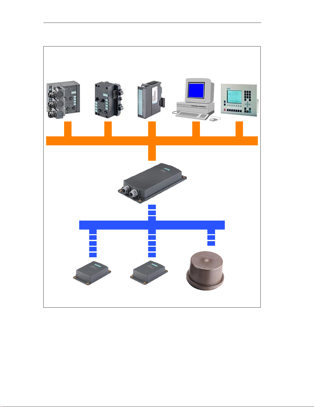
Overview of
the MOBY U
components
MDS: Mobile data memory
SLG: Read and write device
ASM: Interface module
MOBY U – Manual for Configuration, Installation and Service
(4) J31069-D0139-U001-A2-7618
Without bunch With bunch size = 2
Approx. 16.0 Kbyte/
sec
Approx. 14.4 Kbyte/
sec
PROFIBUS
Approx. 8.0 Kbyte/
sec
Approx. 7.2 Kbyte/
sec
2-3
Page 14
Introduction – MOBY U
ASM 452
for
PROFIBUS-DPV1
FC 45/FC 46
ASM 473
for
ET 200X
FC 45/FC 56
ASM 475
for
SIMATIC S7-300/
ET 200M
PC/computer
V .24/RS 422
MOBY API
FC 45/FC 56
Serial data transmission; max. of 115 kbit/sec
SLG U92
with integrated
antenna
SICOMP/IMC
V .24/RS 422
MOBY API
UHF data transmission, 2.45 GHz
MDS U313
Logistics
Figure 2-1 Overview of the MOBY U components
MDS U524
Production
MDS U589
220 °C (cyclic)
2-4
MOBY U – Manual for Configuration, Installation and Service
(4) J31069-D0139-U001-A2-7618
Page 15

Configuration and Installation Guidelines
3
MOBY U – Manual for Configuration, Installation and Service
(4) J31069-D0139-U001-A2-7618
3-1
Page 16

Configuration and Installation Guidelines
3.1 The Fundamentals
MOBY U is a UHF system with powerful features. This makes it much easier
to configure and handle the system.
The range (read/write distance) and communication speed are the same
for all data carriers. However, they do differ in memory size, operational
temperature and lifespan.
Reliable communication due to a homogenous transmission field with
circular polarization in dynamic and static operation. There is no fading
(i.e., temporary ”holes” in the field).
The range (0.15 m to 3 m) permits use throughout production.
The range of the transmission field can be limited (in increments) from
0.5 m to 3 m. This limitation prevents over–ranging and the communication range is clearly specified.
Familiar sources of interference during UHF transmissions such as reflec-
tion and interference have been removed with appropriate technical measures.
Due to the transmission frequency and the robust modulation procedures,
electromagnetic sources of interference can be disregarded.
Simple and flexible installation and customized system integration with
standard hardware and standard function blocks make commissioning fast
and easy.
The robust housing and the power–saving circuiting technology make for
years of maintenance–free operation even under the most rugged of production environments.
Conflicts with other users of the 2.4 GHz frequency band are avoided by
using very low sending power (less than 50 mV per meter at 3-m intervals) and automatic selection of free and interference–free frequency
channels.
Optimum utilization does require adherence to certain criteria.
Transmission window
Time that MDS is in the field (speed and amount of data) during dynamic
transmission
Metal–free space and metallic environment around MDS and SLG
Ambient conditions such as humidity, temperature, chemicals, and so on
Other users of the frequency band at 2.4 GHz
Readiness to communicate: Sleep-time, standby mode, antenna on/off
Bunch size for bunch/multitag
System interface performance
SLG synchronization
Proximity switches
3-2
MOBY U – Manual for Configuration, Installation and Service
(4) J31069-D0139-U001-A2-7618
Page 17
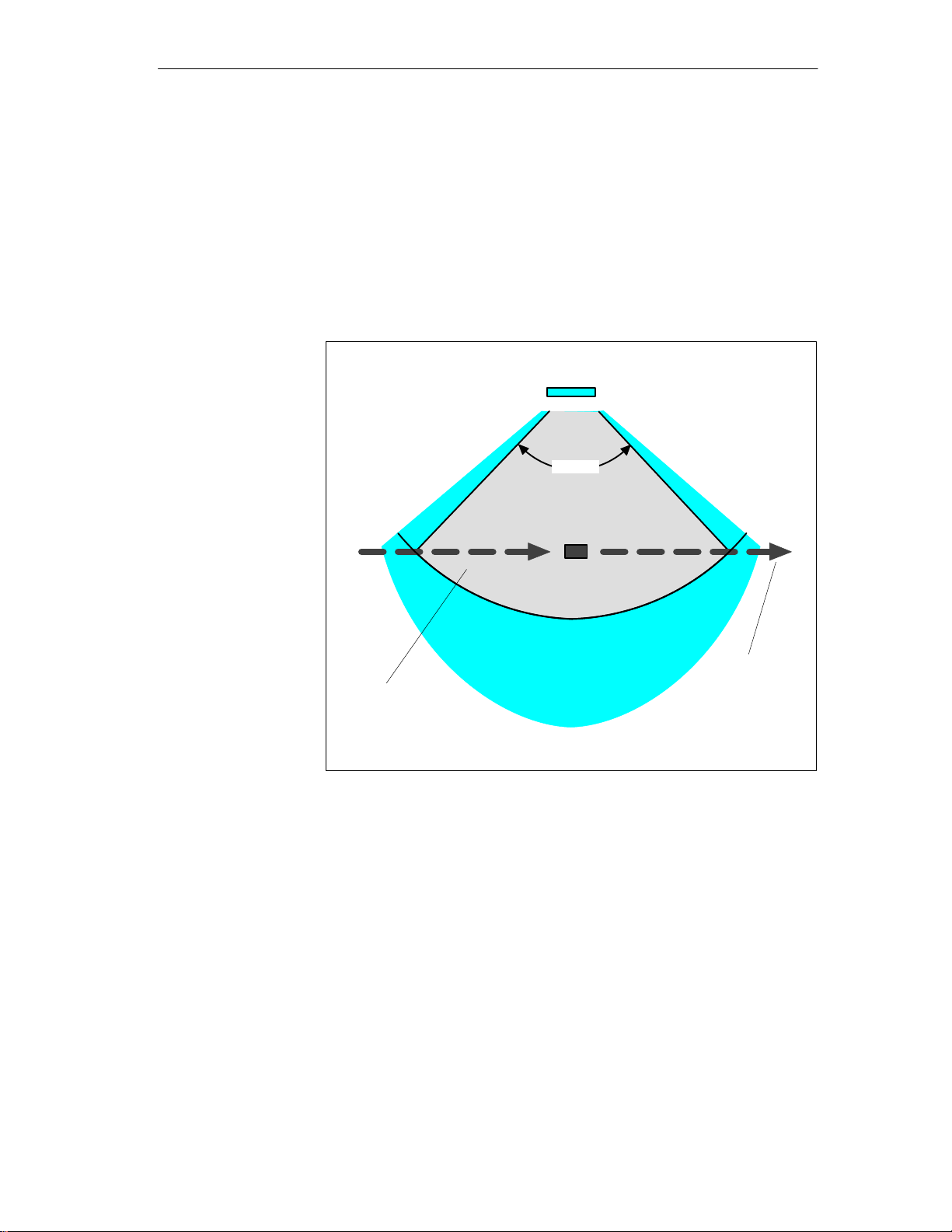
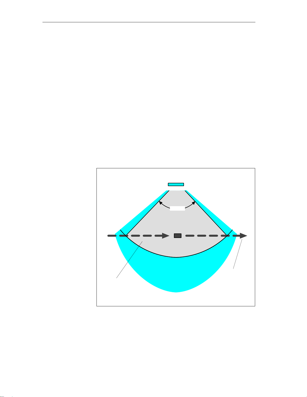
3.1.1 Transmission Window
MOBY U is a UHF system. UHF systems have a relatively wide range despite their low emission power. However, the emission field has a directional
characteristic which depends on the antenna construction. MOBY U has various function zones which depend on direction and distance to keep the
MDS’s power requirements low and to make localization reproducible. The
states and reactions of the affected components vary with the three different
zones of the transmission field (see figure 3-1).
Configuration and Installation Guidelines
SLG U92 with
integrated antenna
> 90°
MDS
Zone 1: r = max. of 3.0 m
Can be adjusted in increments
Zone 2: r = up to approx. 5 m
Transmission
field
Zone 3: r > approx.. 5 m or shielded
Figure 3-1 Status zones for MDS in transmission field of SLG U92
Direction of
MDS’s
movement
Zone 3:
In simplified terms, zone 3 is the UHF–free area. The MDS is asleep and
only wakes up once every < 0.5 sec to listen for an SLG. Power consumption is very low. If other UHF users are in the vicinity and they are using
the same frequency range, this does not shorten the battery life of the
MDS since it does not wake up until it receives a special code.
MOBY U – Manual for Configuration, Installation and Service
(4) J31069-D0139-U001-A2-7618
3-3
Page 18

Configuration and Installation Guidelines
Zone 2:
If the MDS receives this special code in the vicinity of an active SLG, it
enters zone 2 (see figure 3-1). Starting immediately it accepts the SLG
and responds briefly with its own ID. However, the SLG ignores all
MDSs which are not in zone 1 (radius can be parameterized on the SLG
in increments). Power consumption in zone 2 is a little higher than in
zone 3.
Zone 1:
When an MDS enters zone 1, it is registered by the SLG and can begin
exchanging data. All read and write functions can now be performed. The
power consumption of the MDS increases briefly during communication.
Since transmission through the air is very fast, total communication time
is very short. The entire 32–Kbyte data memory can be read in less than
four seconds. This means that data communication hardly uses the battery.
As long as the MDS is located in zone 1, it is ready to exchange data
when requested by the SLG. When no command for the MDS is queued,
it still reports at regular parameterizable intervals with its ID when requested by the SLG. Its behavior corresponds to that of zone 2. Current
consumption drops again accordingly.
General
configuration rules
With MOBY U as a UHF system, the following physical characteristics
must be considered when you configure the system.
The waves in the UHF range spread out in straight lines.
The transmission field (zones 1 and 2) is shaped like an ellipse.
The range of the transmission ellipse up to 3 m can be adjusted in incre-
ments for better identification of the MDS.
In simplified terms, the transmission field can be thought of as a cone and
the midpoint of the antenna is located at the peak of this cone. The angle
of opening is approx. 90°. A primarily homogenous field is then assumed
within this parameterized area. Fading (temporary ”holes” in the field) in
this area is offset by technical measures.
Ideally the MDS should penetrate the transmission cone of its basic sur-
face and exit through the surface area so that the MDS remains as long as
possible in the defined recording field.
Since metallic surfaces reflect the waves, they can also be used for shield-
ing or even deflection. Particularly in typical production environments,
the wealth of metallic objects ensures a relatively uniform dispersion of
the transmission waves.
For optimum data communication, metal should be avoided at least in the
vicinity of the vertical waves.
3-4
Both the MDS and the SLG can be mounted directly on metal.
MOBY U – Manual for Configuration, Installation and Service
(4) J31069-D0139-U001-A2-7618
Page 19

3.2 Basic Requirements
Configuration and Installation Guidelines
FCC Compliance
Statement
This device complies with part 15 of the FCC Rules.
Operation is subject to the following two conditions:
1. This device may not cause harmful interference.
2. This device must accept any interference received, including interference
that may cause undesired operation.
Note
Changes or modifications of this unit may void the user’s authority to operate the equipment.
MOBY U – Manual for Configuration, Installation and Service
(4) J31069-D0139-U001-A2-7618
3-5
Page 20

Configuration and Installation Guidelines
3.3 EMC Guidelines
3.3.1 Preface
These EMC guidelines give you information on the following topics.
Why are EMC guidelines necessary?
What outside interference affects the controller?
How can this interference be prevented?
How can this interference be corrected?
Which standards apply to EMC?
Examples of interference–immune plant setup
This description is only meant for ”qualified personnel.”
Project engineers and planners who are responsible for the plant configu-
ration with the MOBY modules and have to adhere to the applicable
guidelines
Technicians and service engineers who have to install the connection
cables based on this description or correct malfunctions covered by these
guidelines
Warning
!
Non–adherence to the highlighted information may cause hazardous states in
the plant. Individual components or the entire plant may be destroyed as a
result.
3-6
MOBY U – Manual for Configuration, Installation and Service
(4) J31069-D0139-U001-A2-7618
Page 21

3.3.2 General
Configuration and Installation Guidelines
Increasing use of electrical and electronic devices creates the following situation.
Increasing density of the components
Increasing power electronics
Increasing switching speeds
Lower power consumption of the components
The more automation, the greater the danger of the devices interfering with
each other.
Electromagnetic compatibility (EMC) means the ability of an electrical or
electronic device to function correctly in an electromagnetic environment
without bothering its surroundings up to a certain degree.
EMC can be divided into three areas.
Own interference immunity
Immunity against internal (i.e., own) electrical interference
Free interference immunity
Immunity against outside electromagnetic interference
Degree of interference emission
Interference emission and influence of the electrical environment
All three areas must be considered when checking an electrical device.
The MOBY modules are checked for adherence to certain limit values. Since
the MOBY modules are only part of a total system and sources of interference can be created just by combining different components, the setup of a
plant must adhere to certain guidelines.
EMC measures usually comprise a whole package of measures which must
all be taken to obtain an interference–immune plant.
Note
The constructor of the plant is responsible for adherence to the EMC
guidelines whereas the operator of the plant is responsible for radio interference suppression for the entire system.
All measures taken while the plant is being set up prevent expensive
modifications and removal of interference later on.
Naturally, the country–specific rules and regulations must be adhered to.
They are not part of this documentation.
MOBY U – Manual for Configuration, Installation and Service
(4) J31069-D0139-U001-A2-7618
3-7
Page 22
Configuration and Installation Guidelines
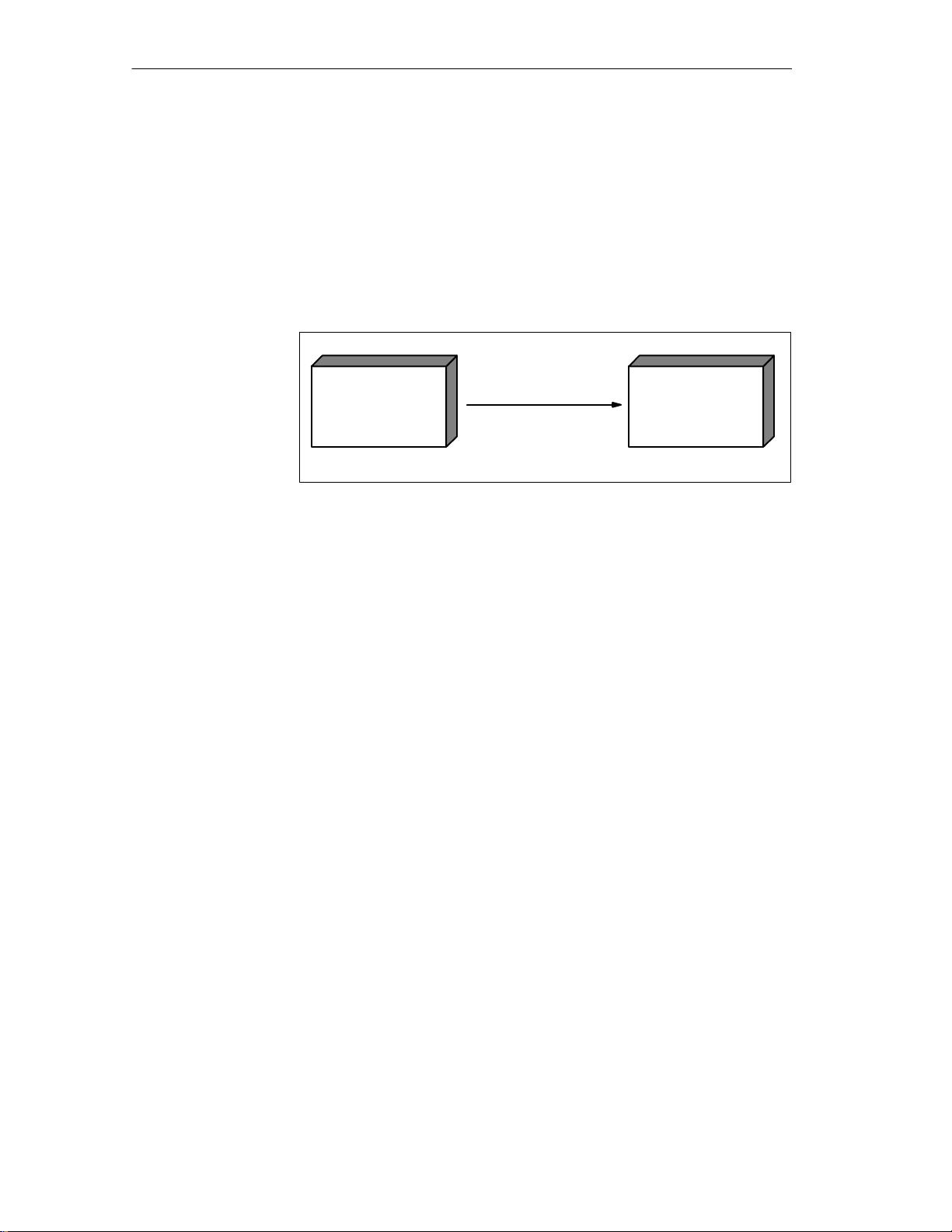
3.3.3 Spreading of Interference
The following three components must be present before interference can occur in a plant.
Source of interference
Coupling path
Potentially susceptible equipment
Source of interference
(instigator)
Example: Drive
Figure 3-2 Spreading of interference
Coupling path
Example: MOBY cable
Potential susceptible
equipment
(malfunctioning device)
Example: ASM 452
If one of these components is missing (e.g., the coupling path between interference source and potentially susceptible equipment), the susceptible device
is not affected even when the source is emitting strong interference.
EMC measures affect all three components to prevent malfunctions caused
by interference. When setting up a plant, the constructor must take all possible precautions to prevent the creation of interference.
Only devices which meet limit value class A of VDE 0871 may be used
in a plant.
All interference–producing devices must be corrected. This includes all
coils and windings.
The cabinet must be designed to prevent mutual interference of the indi-
vidual components or keep this as low as possible.
Precautions must be taken to eliminate external interference.
The next few sections give you tips and hints on good plant setup.
3-8
MOBY U – Manual for Configuration, Installation and Service
(4) J31069-D0139-U001-A2-7618
Page 23

Configuration and Installation Guidelines
Sources of
interference
To obtain a high degree of electromagnetic compatibility and thus a plant
with low interference, you must know the most frequent sources of
interference. These sources of interference must then be removed.
Table 3-1 Sources of interference: Origin and effects
Interference Source
Contactor, electronic
valves
Electric motor Collector Electrical field
Electric welding device Contacts Electrical field
Power pack, pulsed Circuit Electrical and magnetic field,
High–frequency devices Circuit Electromagnetic field
Transmitter
(e.g., plant radio)
Grounding or reference
potential difference
Operator Static charging Electrical discharge current,
High–voltage cable Current flow Electrical and magnetic field,
High–voltage cable Voltage difference Electrical field
Interference Generator Effect on Susceptible
Equipment
Contacts Network interference
Coils Magnetic field
Winding Magnetic field
Transformer Magnetic field, network interfe-
rence, equalizing current
network interference
Antenna Electromagnetic field
Voltage difference Equalizing current
electrical field
network interference
MOBY U – Manual for Configuration, Installation and Service
(4) J31069-D0139-U001-A2-7618
3-9
Page 24
Configuration and Installation Guidelines
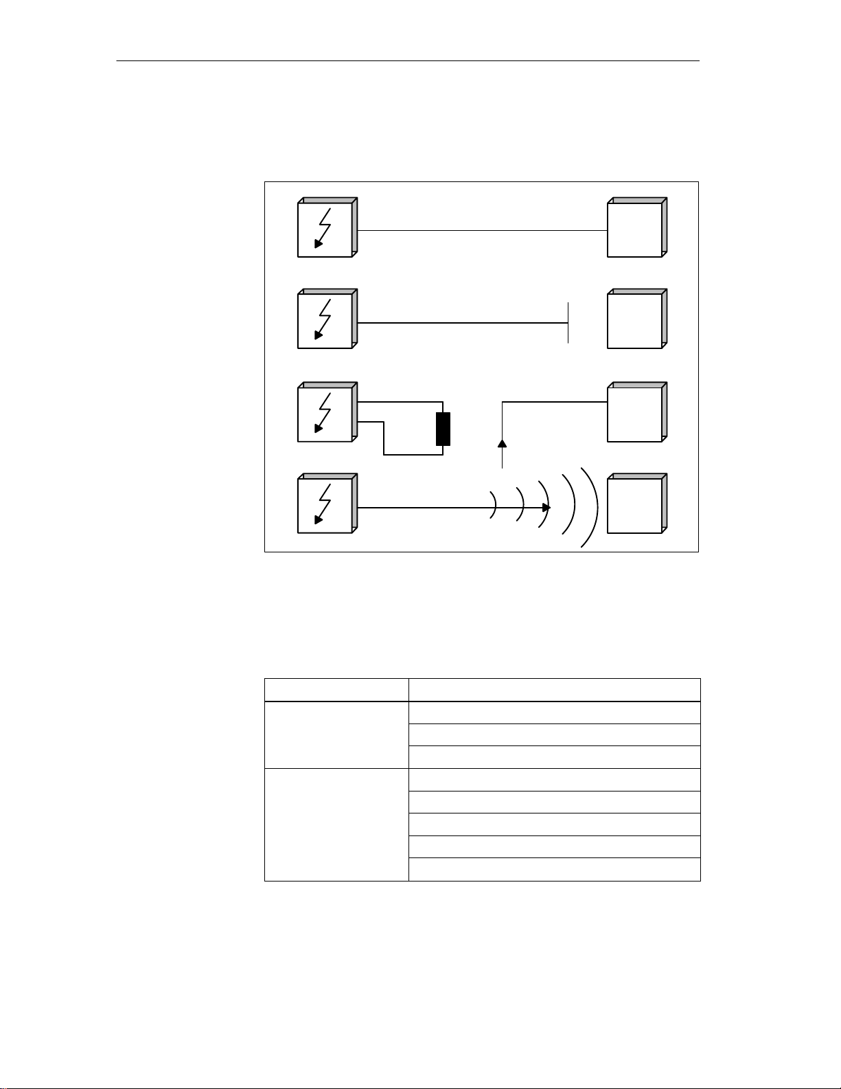
Coupling paths
Before a source of interference can create actual interference, a coupling path
is needed. There are four types of interference coupling.
Galvanic coupling path
I
N
T
E
R
F
E
N
C
E
S
O
U
R
C
E
Capacitive coupling path
Inductive coupling path
Emission coupling
MOBY
ASM or
SLG
MOBY
ASM or
SLG
MOBY
ASM or
SLG
MOBY
ASM or
SLG
S
U
S
C
E
P
T
I
B
L
E
E
Q
U
I
P
M
E
N
T
Figure 3-3 Possible interference coupling
When MOBY modules are used, various components of the total system can
act as coupling paths.
Table 3-2 Causes of coupling paths
Coupling Path
Cables and lines Wrong or poor installation
Shield missing or connected incorrectly
Poor location of the cables
Switching cabinet or SIMATIC housing
Equalizing line missing or incorrectly wired
Grounding missing or faulty
Unsuitable location
Mounted modules not secure
Poor cabinet layout
Caused by
3-10
MOBY U – Manual for Configuration, Installation and Service
(4) J31069-D0139-U001-A2-7618
Page 25
3.3.4 Cabinet Layout
User responsibility for the configuration of an interference–immune plant
covers cabinet layout, cable installation, grounding connections and correct
shielding of the cables.
Note
Information on EMC–proof cabinet layout can be taken from the setup
guidelines of the SIMATIC controller.
Configuration and Installation Guidelines
Shielding by
housing
Magnetic and electrical fields as well as electromagnetic waves can be kept
away from susceptible equipment by providing a metallic housing. The better
induced interference current is able to flow, the weaker the interference field
becomes. For this reason all housing plates or plates in the cabinet must be
connected with each other and good conductivity ensured.
Figure 3-4 Shielding by the housing
When the plates of the switching cabinet are insulated against each other, this
may create a high–frequency–conducting connection with ribbon cables and
high–frequency terminals or HF conductive paste. The larger the connection
surface, the better the high–frequency conductivity. Connection of simple
wires cannot handle this task.
MOBY U – Manual for Configuration, Installation and Service
(4) J31069-D0139-U001-A2-7618
3-11
Page 26
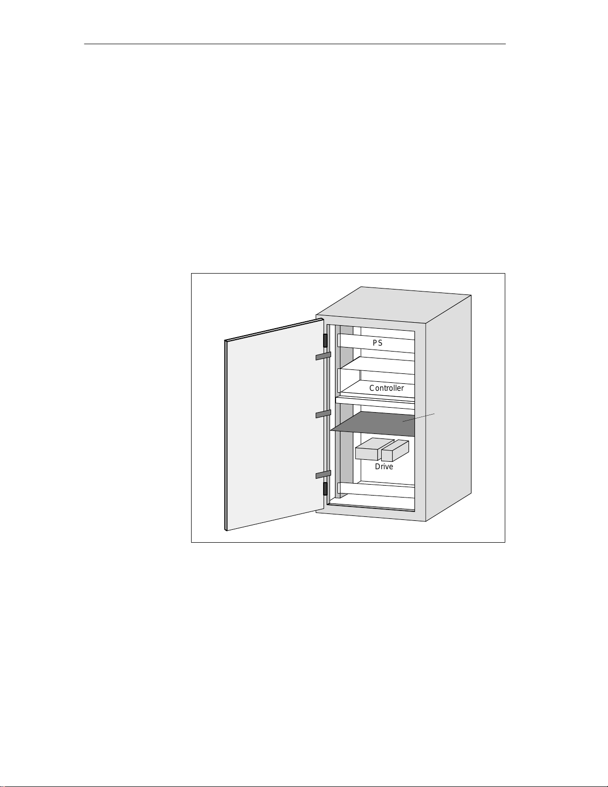
Configuration and Installation Guidelines
Avoidance of
interference with
optimized layout
Installation of SIMATIC controllers on conductive mounting plates (not
painted) is a good way to get rid of interference. Adhering to the guidelines
when laying out the switching cabinet is a simple way to avoid interference.
Power components (transformers, drives, load power packs) should not be
located in the same room with controller components (relay control parts,
SIMATIC S5).
The following principles apply.
1. The effects of interference decrease the greater the distance between
source of interference and susceptible equipment.
2. Interference can be decreased even more by installing shielding plates.
3. Power lines and high–voltage cables must be installed separately at least
10 cm away from signal lines.
PS
Controller
Drive
Figure 3-5 Avoidance of interference with optimal layout
Shield
plate
3-12
MOBY U – Manual for Configuration, Installation and Service
(4) J31069-D0139-U001-A2-7618
Page 27
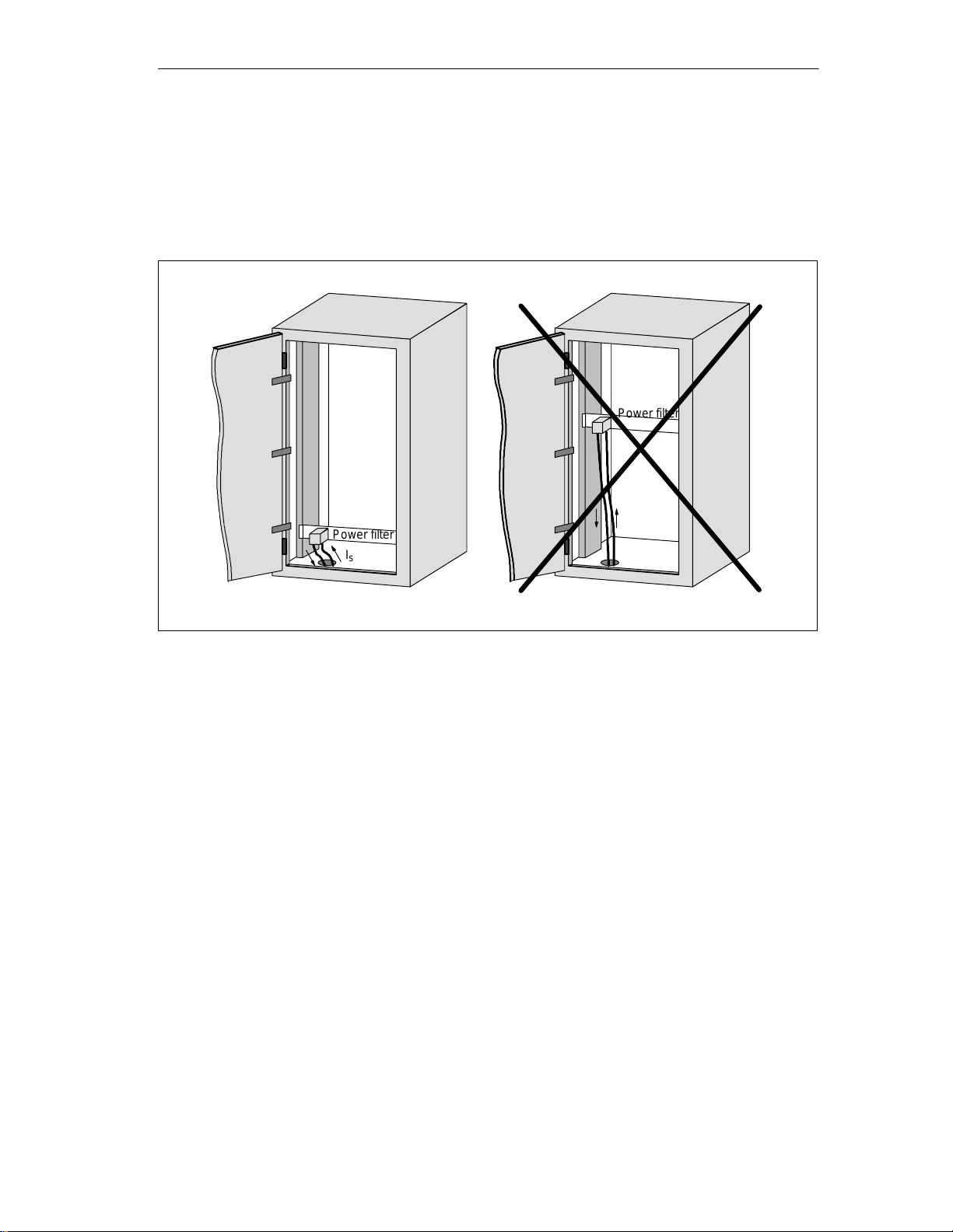
Configuration and Installation Guidelines
Filtering the
voltage
Power filters can be used to combat external interference over the power
network. In addition to correct dimensioning, proper installation is very
important. It is essential that the power filter be mounted directly on the
cabinet leadin. This keeps interference current from entering the cabinet by
filtering it out from the beginning.
Right
Power filter
I
s
Wrong
Power filter
I
s
Figure 3-6 Filtering the voltage
I
= Interference
s
current
MOBY U – Manual for Configuration, Installation and Service
(4) J31069-D0139-U001-A2-7618
3-13
Page 28
Configuration and Installation Guidelines
3.3.5 Avoiding Sources of Interference
Inclusion of interference sources in a plant must be avoided to achieve a
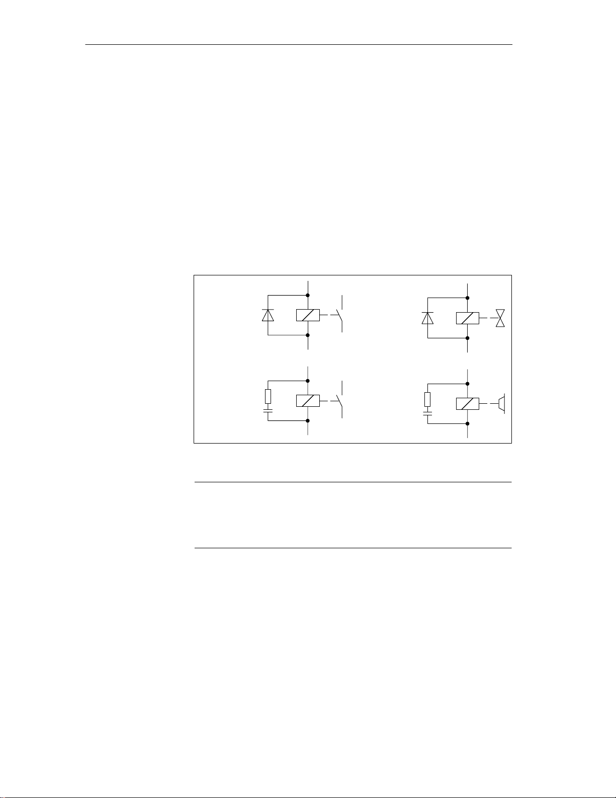
higher degree of interference immunity. All switched inductivity is frequently a source of interference in plants.
Suppression of
inductivity
Relays, contactors, etc. generate interference voltages which must be
suppressed with one of the following circuits.
24 V coils create up to 800 V even with small relays and 220 V coils generate interference voltages of several kV when the coil is switched. Free wheeling diodes or RC circuits can be used to prevent interference voltage and thus
also inductivity in lines which must be installed parallel to the coil line.
Relay coils
Contactors
Figure 3-7 Suppression of inductivity
Valves
Brakes
3-14
Note
All coils in the cabinet must be interference–suppressed. Don’t forget the
valves and motor brakes. A special check must be made for neon lamps in
the switching cabinet.
MOBY U – Manual for Configuration, Installation and Service
(4) J31069-D0139-U001-A2-7618
Page 29
3.3.6 Equipotential Bonding
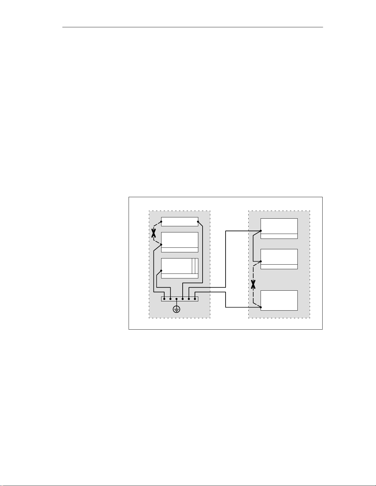
Differences in potential may be created between the parts of the plant by differing layout of plant parts and differing voltage levels. When the parts of the
plant are connected with signal lines, equalizing currents flow over the signal
lines. These equalizing currents may distort the signals.
This makes it very important to provide correct equipotential bonding.
The cross section of the equipotential bonding line must be large enough
(at least 10 mm2).
The distance between signal cable and equipotential bonding line must be
as short as possible (effects of antenna).
A fine–wire line must be used (better high–frequency conductivity).
When the equipotential bonding lines are connected to the central equipo-
tential bonding rail, power components and non–power components must
be combined.
Configuration and Installation Guidelines
Cabinet 1 Cabinet 2
Power pack
EU
Wrong
EU
EU
PLC
Wrong
Drive
Figure 3-8 Equipotential bonding
The better the equipotential bonding in a plant, the less interference is
created by potential fluctuations.
Don’t confuse equipotential bonding with the protective ground of a plant.
Protective ground prevents the creation of high touch voltages on defective
devices.
MOBY U – Manual for Configuration, Installation and Service
(4) J31069-D0139-U001-A2-7618
3-15
Page 30
Configuration and Installation Guidelines
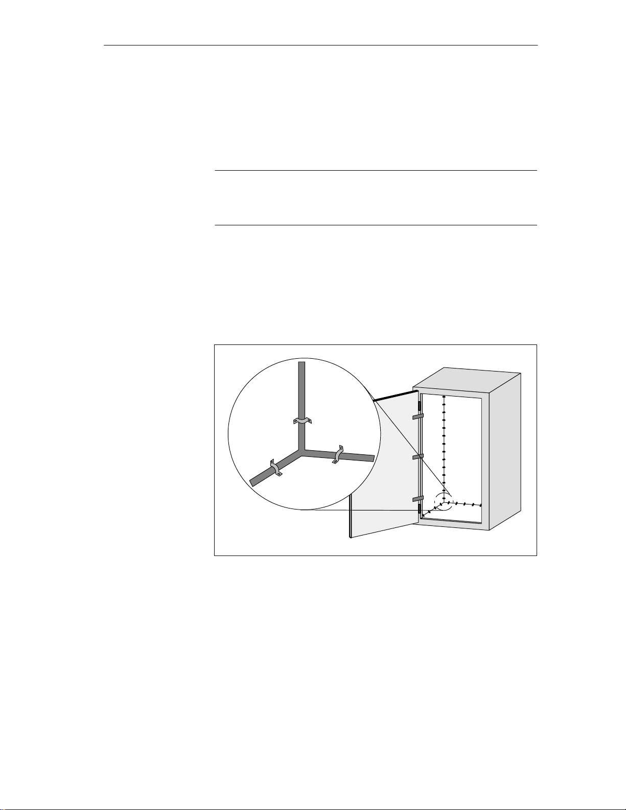
3.3.7 Shielding the Cables
To suppress interference coupling in the signal cables, these cables must be
shielded.
The best shielding is achieved by installation in steel tubing. However, this is
only required when the signal line has to be led through high interference.
Use of cables with braided shields is usually sufficient. In both cases, correct
connection is decisive for shielding.
Note
A shield which is not connected or is not connected correctly is not a shield.
The following principles apply.
With analog signals, the shield is connected on one side to the receiver
side.
With digital signals, the shield is applied on both sides to the housing.
Since interference signals are frequently in the HF range (> 10 kHz), a
large–surface shield which meets HF requirements is needed.
Figure 3-9 Shielding the cables
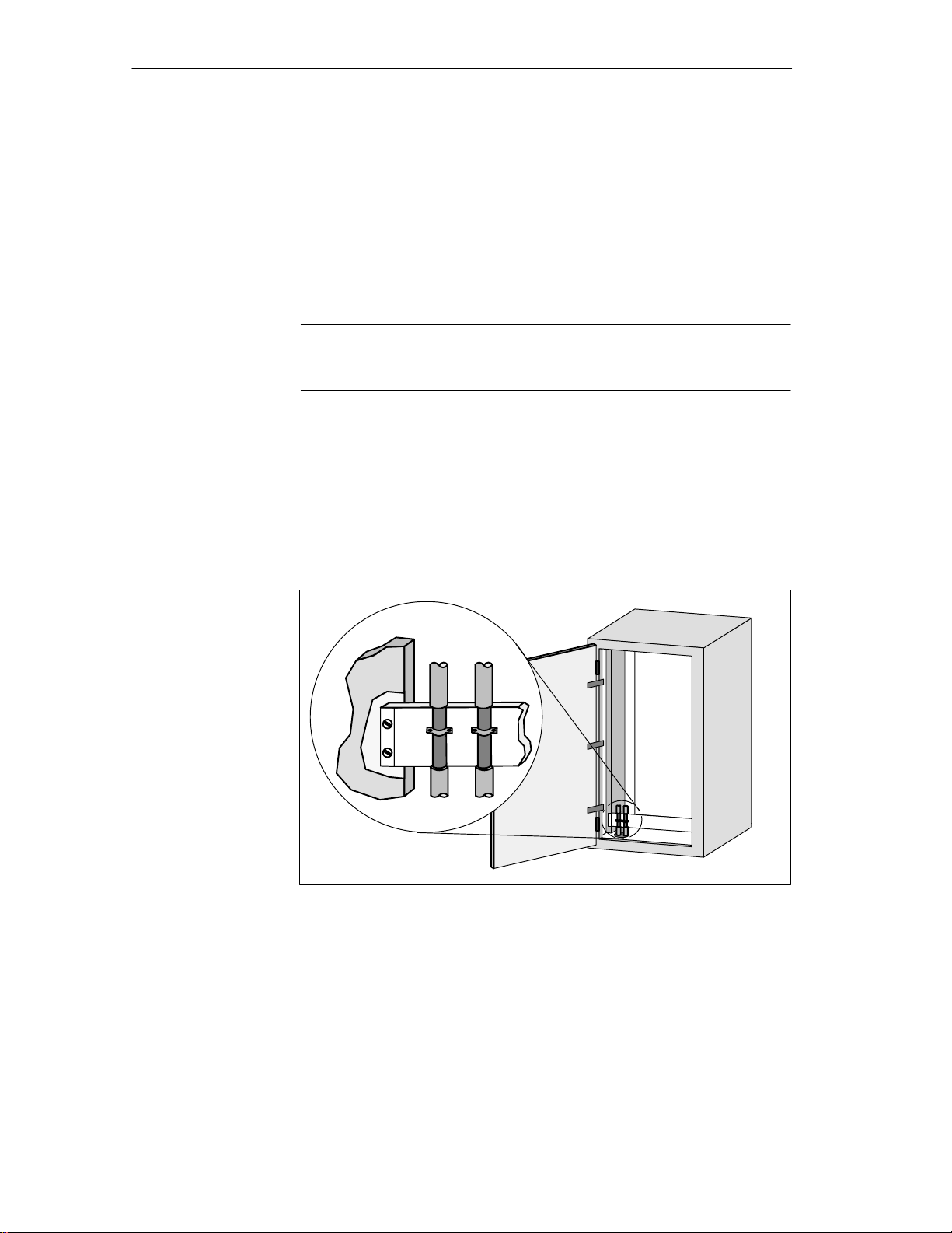
The shield bar must be connected (over a large surface for good conductivity)
to the switching cabinet housing. It must be located as close as possible to the
cable leadin. The cables are bared and then clamped to the shield bar (high–
frequency clamps) or bound with cable binders. Make sure that the connection is very conductive.
3-16
MOBY U – Manual for Configuration, Installation and Service
(4) J31069-D0139-U001-A2-7618
Page 31

Configuration and Installation Guidelines
Cable binder
Figure 3-10 Connecting the shield bar
The shield bar must be connected with the PE bar.
Remove
paint
If shielded cables have to be interrupted, the shield must be continued on the
plug case. Only suitable plug connectors may be used.
Fold back shield by 180° and
then connect with plug case.
Rubber sleeve
Figure 3-11 Interruption of shielded cables
If intermediate plug connectors which have no shield connection are used,
the shield must be continued with cable clamps at the point of interruption.
This gives you a large–surface, HF conductive connection.
MOBY U – Manual for Configuration, Installation and Service
(4) J31069-D0139-U001-A2-7618
3-17
Page 32

Configuration and Installation Guidelines
3.3.8 Basic EMC Rules
Often the adherence to a few elementary rules is sufficient to ensure electromagnetic compatibility (EMC). The following rules should be observed when
setting up the switching cabinet.
Shielding by the
housing
Surface–shaped
grounding
connection
Protect the programmable controller from external interference by instal-
ling it in a cabinet or housing. The cabinet or housing must be included in
the grounding concept.
Shield the programmable controller from electromagnetic fields of induc-
tivity by using divider plates.
Use metallic plug connector cases for shielded data transmission lines.
Connect all inactive metallic parts over a large surface with low ohmic
HF.
Planning the cable
installation
Make a large–surface connection between the inactive metallic parts and
the central grounding point.
Don’t forget to include the shield bar in the grounding concept. This
means that the shield bar itself must be connected over a large surface
with ground.
Do not use aluminum parts for grounding connections.
Divide the cables into groups and install the groups separately.
Always install high–voltage cables and signal lines in separate ducts or
bundles.
Always have the entire cabling enter the cabinet on only one side and at
only one level.
Install the signal lines as close as possible to grounding surfaces.
Twist the ”to” and ”from” conductors of individual cables in pairs.
3-18
MOBY U – Manual for Configuration, Installation and Service
(4) J31069-D0139-U001-A2-7618
Page 33

Shielding the
cables
Power and signal
filters
Configuration and Installation Guidelines
Shield the data transmission cables and apply the shield on both sides.
Shield the analog cables and apply the shield on one side (e.g., on the
drive).
Always apply the cable shields over a large surface on the cabinet leadin
on the shield bar and affix these with clamps.
Continue the applied shield without interruption up to the module.
Use braided shields and not foil shields.
Use only power filters with metal housing.
Connect the filter housing (over a large surface and with low ohmic HF)
to cabinet ground.
Never secure the filter housing on painted surfaces.
Secure the filter on the cabinet’s entry point or in the direction of the
source of interference.
MOBY U – Manual for Configuration, Installation and Service
(4) J31069-D0139-U001-A2-7618
3-19
Page 34

Configuration and Installation Guidelines
3.4 MOBY Shielding Concept
With MOBY U, the data are transferred between ASM and SLG at a speed of
19200, 38400, 57600 or 115200 Baud over an RS 422 interface. The distance
between ASM and SLG can be up to 1000 m. With respect to cabling,
MOBY should be handled like a data processing system. Special attention
should be paid to shield installation for all data cables. The following figures
shows the primary factors needed for a reliable setup.
3.4.1 SLG Cable between ASM 475 and SLG U92 with RS 422
Layout of an
S7–300 with MOBY
When the SLG U92 is connected to the ASM 475, it is essential to use a
shield connection terminal for the cable shield. Shield connection terminals
and holder brackets are standard components of the S7–300 product family.
Shield connection terminal
Cable to SLG1
Figure 3-12 Layout of the ASM 475 with shield connecting element
Cable to SLG2
Holding
bracket
3-20
MOBY U – Manual for Configuration, Installation and Service
(4) J31069-D0139-U001-A2-7618
Page 35

Configuration and Installation Guidelines
3.5 SLG Cable and Plug Connector Allocations (RS 422)
The jacket used for MOBY SLG connection cables is made of polyurethane
(PUR in acc. w. VDE 0250). This gives the cables very good resistance to oil,
acid, lye and hydraulic fluid.
3.5.1 Cable Configuration
The cable between ASM and SLG has six cores plus shield. Four of these
cores are allocated to the serial data interface. The power supply of the SLG
requires two cores. Regardless of the wire diameter, data can usually be
transmitted up to a distance of 1000 m.
The voltage on the connection cable drops due to the power consumption of
the SLG. For this reason, the permitted cable length is usually shorter than
1000 m. It depends on the current consumption of the SLG and the ohmic
resistance of the connection cable. The following table gives you an overview of the permitted cable lengths.
Grounding of the
SLG cable
Table 3-3 Cable configuration
Conductor
Cross Section in
1 The resistance values are average values. They refer to the ”to” and ”from” conductors.
2 When these conductor cross sections are used, crimp contacts must be used in the SLG
Field highlighted in gray:
2
mm
2
0.07
0.2 0.5 185 85 210
0.5 0.8 70 230 570
2
0.8
2
1.5
A single wire has half the specified resistance.
connection plug. These crimp contacts are not included with the connection plugs.
Standard cable recommended by Siemens (LiYC11Y, 6 x 0.25, shielded). The cable is
available from SIEMENS under the order number ”6GT2 090-0A...”.
Conductor
Cross Section in
mm
2
0.3
2
1.0
2
1.4
Resistance
1
/km
550 30 70
50 320 800
24 660 1000
SLG U92 with RS 422
(I = 300 mA) Max. Cable
Length in m for
UV = 24 V UV = 30 V
We recommend always grounding the shield of the SLG cable over a large
surface to the grounding rail.
MOBY U – Manual for Configuration, Installation and Service
(4) J31069-D0139-U001-A2-7618
3-21
Page 36

Configuration and Installation Guidelines
Extra power pack
for SLG
When an extra power pack is installed in the vicinity of the SLG, you can
always use the maximum cable length of 1000 m between ASM and SLG.
Note
The 24 V power supply (pin 2 on the SLG connector)
may not be connected to the ASM.
6–core (with 24 V connection)
24 V =
90 –
230 V
Max. of 1000 m
Figure 3-13 SLG with extra power pack
SLG
The power pack in our drawing can be obtained from Siemens under the
number 6GT2 494-0AA00 (see chapter 7.2).
The cable from the extra power pack to the SLG must be provided by the
customer.
3.5.2 Plug Connector Allocations
Table 3-4 Plug connector allocation of the SLG connector
Plug on SLG
2
3
1
6
4
5
Caution
!
When the extra power pack is used in the vicinity of the SLG, do not wire
the +24 V pin to the ASM. (Cf. table 3-4.)
Pin
1 - Receive
2 +24 Volt
3 Ground (0 V)
4 + Send
5 - Send
6 + Receive
Cable shield
Name
3-22
MOBY U – Manual for Configuration, Installation and Service
(4) J31069-D0139-U001-A2-7618
Page 37

Configuration and Installation Guidelines
Installing the SLG
plug connector
If the user has to turn the SLG plug of a prefabricated cable in a different
direction, follow the diagram below and position the contact carrier
differently. The plug connector on the SLG cannot be turned.
Knurled screw for
vibration–proof connections
(no tools required)
Removable housing cover
for easy mounting
Cable holder with cage claw
Crimp contacts
for use with
strong vibration*
Contact carrier must be
affixed at 7 positions.
* Manual crimp pliers: order from:
Hirschmann,
72606 Nürtingen
Tel. 07127/14-1479;
Type XZC0700,
Order no.: 932 507-001
Figure 3-14 Drawing of how to mount the SLG plug connector
MOBY U – Manual for Configuration, Installation and Service
(4) J31069-D0139-U001-A2-7618
3-23
Page 38

Configuration and Installation Guidelines
3.5.3 Connection Cables
Connection cable
ASM 452/473 ↔
SLG U92 with
RS 422
6GT2 091-1C...
22.5
18.5
Two 5–pin, round M12 plug
connectors
X1/2
X1/3
x1
X2
X1/1
X1/4
X2/3
X2/1
X1/5
X2/5
SLG plug (socket)
2m
White
Brown
Green
Yellow
Gray
Pink
Figure 3-15 Connection cable ASM 452/473 ↔ SLG U92 with RS 422
The connection cable can be ordered in the following lengths.
Table 3-5 Cable lengths of ASM 475 ↔ SLG U92 with RS 422
Length of Stub Line in m Order Number
1
2
5 6GT2 091-1CH50
10 6GT2 091-1CN10
20 6GT2 091-1CN20
50 6GT2 091-1CN50
2
2
6GT2 091-1CH20
6GT2 091-2CH20
6
1
4
5
3
2
3-24
1 Inexpensive standard length
2 Connection cable with straight SLG plug
MOBY U – Manual for Configuration, Installation and Service
(4) J31069-D0139-U001-A2-7618
Page 39
Connection cable
ASM 475 ↔
SLG U92 with
RS 422
6GT2 091-0E...
Configuration and Installation Guidelines
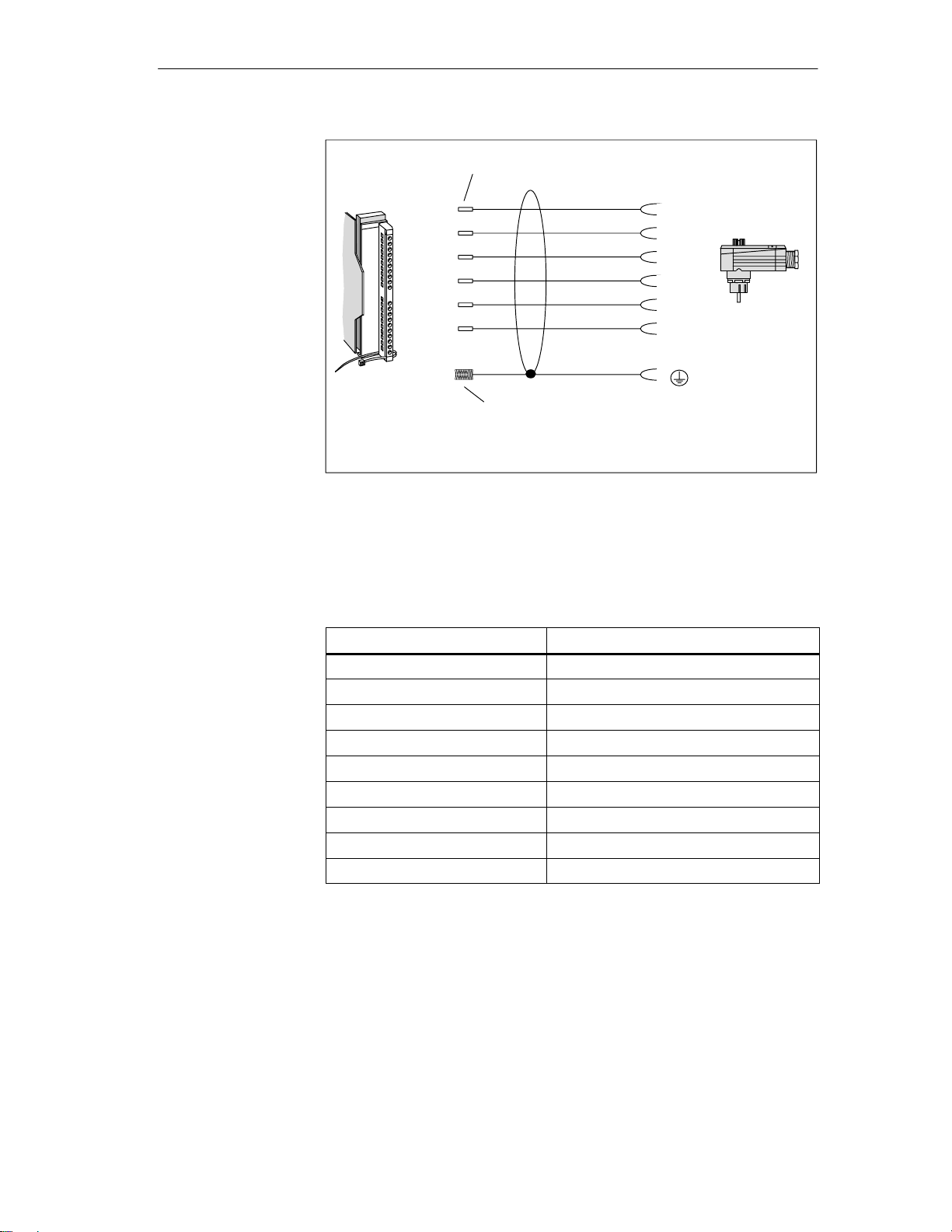
Cable with core sleeves
4 (12)
5 (13)
6 (14)
7 (15)
8 (16)
9 (17)
Cable shield open
16GT2 091-0E... with angled SLG plug (standard)
6GT2 091-2E... with straight SLG plug (not shown)
White
Brown
Green
Yellow
Pink
Gray
(Shield)
Figure 3-16 Connection cable ASM 475 ↔ SLG U92 with RS 422
6
1
4
5
2
3
SLG plug
(socket)
1
The connection cable can be ordered in the following lengths.
Table 3-6 Cable lengths of ASM 475 ↔ SLG U92 with RS 422
Length of Stub Line in m Order Number
2 6GT2 091-0EH20
5 6GT2 091-0EH50
10 6GT2 091-0EN10
20 6GT2 091-0EN20
50 6GT2 091-0EN50
1
2
1
5
1
10
1
50
1 With straight SLG plug
6GT2 091-2EH20
6GT2 091-2EH50
6GT2 091-2EN10
6GT2 091-2EN50
MOBY U – Manual for Configuration, Installation and Service
(4) J31069-D0139-U001-A2-7618
3-25
Page 40

Configuration and Installation Guidelines
3.6 SLG Cable and Plug Allocations (RS 232)
With MOBY U, the data are transferred between PC and SLG at a speed of
19200, 38400, 57600 or 115200 Baud over an RS 232 interface. The distance
between PC and SLG can be up to 32 m.
The SLG cable is comprised of a stub line between PC and SLG and a connection line for the 24 V power supply of the SLG from a standard power
pack (see chapter. 7.2).
The connection line for the power supply has a fixed length of 5 m.
The stub line between PC and SLG is available in two lengths (5 m and
20 m).
The connection cable for the power supply can be extended with a stub line
(order number 6GT2494-0AA0).
The jacket used for MOBY SLG connection cables is made of polyurethane
(PUR in acc. w. VDE 0250). This gives the cables very good resistance to oil,
acid, lye and hydraulic fluid.
3.6.1 Cable Configuration
The RS 232 cable between PC and SLG has three cores plus shield. The
cable for the power supply of the SLG requires two cores.
Grounding of the
SLG cable
Power pack for
SLG U92
We recommend always grounding the shield of the SLG cable over a large
surface to the grounding rail.
6GT2 494-0AA00
6GT2 591-1C...
24 V =
90 –
230 V
Max. of 32 m (with RS 232)
SLG
3-26
Figure 3-17 Wide–range power pack for SLG U92
The power pack in our drawing can be obtained from Siemens under the
number 6GT2 494-0AA00 (see chapter 7.2).
MOBY U – Manual for Configuration, Installation and Service
(4) J31069-D0139-U001-A2-7618
Page 41

3.6.2 Connection Cables with Lengths
Connection cable
for PC SLG U92
with RS 232
6GT2 591-1C...
Configuration and Installation Guidelines
N6RFFR
5x RBC162/1AG
1x RBC162AG
KVPG11
5 m
Figure 3-18 Connection cable for PC ↔ SLG U92
Table 3-7
Plug allocation of SLG plug and submin D plug
SLG (RS 232) N6RFFR Sensor 763 (Pin) LIYC11Y Sub D 9B
GND 1 Green 5 (GND)
Vdc+ (power +) 2 2 (24 V DC)
Vdc– (power –) 3 1 (GND) brown
TxD (send data) 4 White 2 (RxD)
n.c. 5
RxD (receive data) 6 Brown 3 (TxD)
Shield GND Shield Housing
LIY11Y-6x0,25
5/20 m
Sensor 763
Nameplate
Sub D 9B
FPGHR
white
The connection cable can be ordered in the following lengths.
Table 3-8 Cable lengths for PC ↔ SLG U92 with RS 232
Length of Stub Line in m
5 6GT2 591-1CH50
20 6GT2 591-1CN20
MOBY U – Manual for Configuration, Installation and Service
(4) J31069-D0139-U001-A2-7618
Order Number
3-27
Page 42

Configuration and Installation Guidelines
Non prefabricated
cables
Users who want to make their own cables can order the following
components from the MOBY catalog.
Table 3-9 Components for individually fabricated cables
Component
SLG connection plug with screw terminals with angled output
SLG stub line;
T ype: 6 x 0.25 mm
M12 socket
for extension of the 24 V cable
2
6GT2 090-0BA00
6GT2 090-0AN50 (50 m)
6GT2 090-0AT12 (120 m)
6GT2 090-0AT80 (800 m)
6GT2 390-1AB00
Order Number
3-28
MOBY U – Manual for Configuration, Installation and Service
(4) J31069-D0139-U001-A2-7618
Page 43

Configuration and Installation Guidelines
3.7 Service Cable and Plug Allocations
3.7.1 Cable Configuration
3.7.2 Plug Allocations
3.7.3 Connection Cables with Lengths
MOBY U – Manual for Configuration, Installation and Service
(4) J31069-D0139-U001-A2-7618
3-29
Page 44

Configuration and Installation Guidelines
3-30
MOBY U – Manual for Configuration, Installation and Service
(4) J31069-D0139-U001-A2-7618
Page 45

Mobile Data Memories
4
MOBY U – Manual for Configuration, Installation and Service
(4) J31069-D0139-U001-A2-7618
4-1
Page 46
Mobile Data Memorie
s
4.1 Introduction
Application area
Construction and
functions
MOBY identifica tion system s ensure that a product is ac com panie d by
meaningful da ta from the be ginning to the end.
First, mobile data memories are affixed to the product or its carrier or its
packaging, then conductively written, changed and read. All information on
production and material flow control is located right on the product. Its
robust construction permits use in rugged environments and makes the MDS
insensitive to many chemical substances.
The primary com ponents of mobil e da ta mem ories (MDSs) are logic, an
antenna, a data memory and a battery.
To keep the MDS’s power consumption low and make localization
reproducible, MOBY U has different function zones based on direction and
distance. The three different zones of the transmission field (see figure 4-1)
represent different states and reactions of the affected components.
SLG U92 with
integrated antenna
> 90°
4-2
MDS
Zone 1: r = max. of 3.0 m
Can be adjusted in increments
Zone 2: r = up to approx. 5 m
Transmission
field
Zone 3: r > approx. 5 m or shielded
Figure 4-1 Status zones for MDS in transmission field of SLG U92
MOBY U – Manual for Configuration, Installation and Service
(4) J31069-D0139-U001-A2-7618
Direction of
MDS’s
movement
Page 47

Mobile Data Memorie
s
Zone 3:
In simplified terms, zone 3 is the UHF–free area. The MDS is asleep and
only wakes up to listen for an SLG once every < 0.5 sec. Power consumption is very low. If other UHF users are in the vicinity and they are using
the same frequency range, this does not shorten the battery life of the
MDS since it does not wake up until it receives a special code.
Zone 2:
If the MDS receives this special code in the vicinity of an active SLG, it
enters zone 2 (see figure 4-1). Starting immediately it accepts the SLG
and responds briefly with its own ID. However, the SLG ignores all
MDSs which are not in zone 1 (radius can be parameterized on the SLG
in increments). Power consumption in zone 2 is a little higher than in
zone 3.
Zone 1:
When an MDS enters zone 1, it is registered by the SLG and can begin
exchanging data. All read and write functions can now be performed. The
power consumption of the MDS increases briefly during communication.
Since transmission through the air is very fast, total communication time
is very short. The entire 32–Kbyte data memory can be read in less than
four seconds. This means that data communication hardly uses the battery.
As long as the MDS is located in zone 1, it is ready to exchange data
when requested by the SLG. When no command for the MDS is queued,
it still reports at regular parameterizable intervals with its ID (sleep–time,
similar to t–ABTAST with MOBY I) when requested by the SLG. Its
behavior corresponds to that of zone 2. Current consumption drops again
accordingly.
MOBY U – Manual for Configuration, Installation and Service
(4) J31069-D0139-U001-A2-7618
4-3
Page 48
Mobile Data Memorie
s
Overview
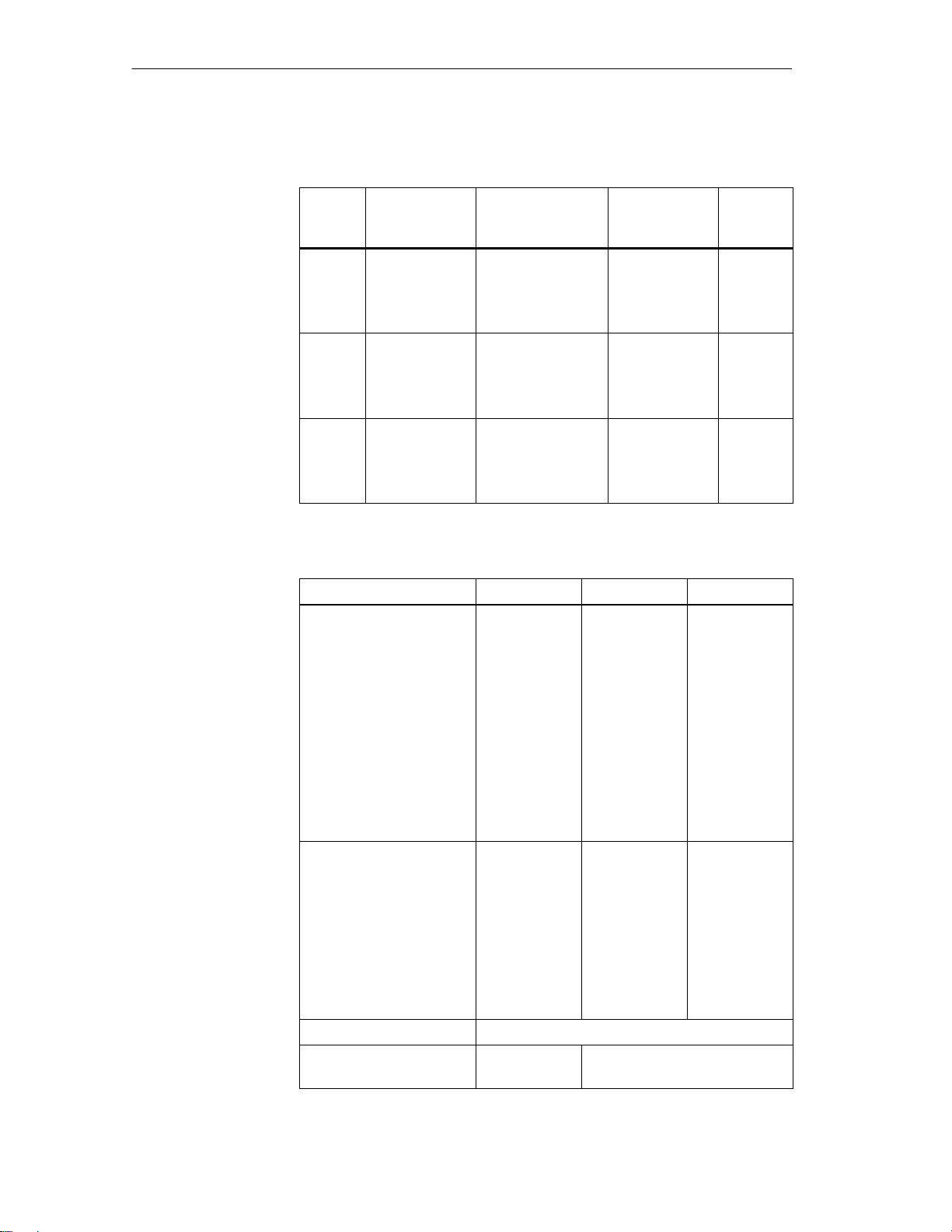
Table 4-1 Overview of the MDS
Operational/ambie
nt conditions
MDS
Type
MDS
U313
MDS
U524
MDS
U589
Table 4-2 Operational/ambient conditions of the MDS
Proof of the physical strength
is provided by the vibration
test in acc. w. DIN EN
721-3-7, class 7 M3
Memory Size T emperature Range
(during Operation)
2–Kbyte RAM
32–bit fixed code
128–bit read–
only memory
32–Kbyte RAM
32–bit fixed code
128–bit read–
only memory
32–Kbyte RAM
32–bit fixed code
128–bit read–
only memory
–25 to +70 °C 111 x 67 x 23.5 IP 67
–25 to +85 °C 111 x 67 x 23.5 IP 68
–25 to +220 °C
(cyclic)
MDS U313 MDS U524 MDS U589
Ø 30 x 10 IP 68
Dimensions
L x W x H
(in mm)
Protection
Rating
Test conditions
Frequency range
Amplitude of the dis-
placement
Acceleration
Test duration per axis
Speed of passage
Proof of the physical strength
is provided by the continuous
shock test in acc. w. DIN EN
721-3-7, class 7 M3
Test conditions
Acceleration
Duration
Test duration per axis
Torsion and bending stress Not permitted
Protection rating in acc. w.
EN 60529
IP 67 IP 68
4-4
MOBY U – Manual for Configuration, Installation and Service
(4) J31069-D0139-U001-A2-7618
Page 49

Mobile Data Memorie
s
Table 4-2 Operational/ambient conditions of the MDS
MDS U589MDS U524MDS U313
Ambient temperature
During operation in acc.
w.
EN 60 721-3-7,
class 7 K4
During transportation
and storage in acc. w.
EN 60 721-3-7,
class 7 K3
Temperature gradient over
storage temperature range, in
acc. w. DIN IEC 68, part
2-14
Temperature gradient with
fast temperature change in
acc. w.
DIN IEC 68, part 2-14
Cleaning with water jet – Max. of 5 min at
–25 to +70 °C –25 to +85 °C –25 to +220 °C
(cyclic)
–40 to +85 °C –40 to +85 °C –40 to +85 °C
3 °C/min
Change from 0 °C to 70 °C (85 °C) in 10 sec;
Duration: 30 min;
Change from 70 °C (85 °C) to 0 °C in 15 sec;
100 cycles
max. of 2 bar
Chemical resistance
Definition of IP 67
– Protection against penetration of dust (dustproof)
– Total protection against accidental touch
– Protection against stream of water
Definition of IP 68:
– Protection against penetration of dust (dustproof)
– Total protection against accidental touch
– The MDS can be continuously submerged in water. Ask manufacturer for condi-
tions.
MOBY U – Manual for Configuration, Installation and Service
(4) J31069-D0139-U001-A2-7618
4-5
Page 50

Mobile Data Memorie
s
4.2 MDS U313
The MDS U313 is a mobile data memory (MDS) with a storage capacity of 2
Kbytes for use in transportation and logistics. The particularly low current
consumption guarantees a long life of 5 years. The interference–immune and
robust MDS can be read and written at a maximum distance of 3 m. The
MDS U313 is addressed directly with byte memory accesses. The transmission frequency in the ISM frequency band at 2.4 GHz makes the MDS’s net
data transmission speed very fast (up to 16 Kbyte/sec without multitaging
and up to 8 Kbyte/sec with multitaging of two MDSs).
Ordering data
Technical data
Figure 4-2 MDS U313
Table 4-3 Ordering data for the MDS U313
Order No.
MDS U313 mobile data memory with 2–Kbyte
RAM, MDS ID number (32 bits), read–only memory (128 bits)
Table 4-4 Technical data of the MDS U313
Fixed code memory
Read–only memory 128 bits, to be written once by user
Application memory
Memory technology
Memory size
Memory organization
Data retention time 10 years
MTBF (at +40°C) 2.5 x 10⁶ hours (without conside-
Read/write distance 0.15 m up to 3 m
Depends on direction No
Multitaging capability Yes
Power supply Battery
6GT2500-3BD10
MDS ID number (32 bits)
RAM
2 Kbytes
Byte access
ring battery)
4-6
MOBY U – Manual for Configuration, Installation and Service
(4) J31069-D0139-U001-A2-7618
Page 51

Mobile Data Memorie
s
Table 4-4 Technical data of the MDS U313
Battery lifespan > 5 years at 25°C1); no replace-
ment
Shock, vibration in acc. w. DIN EN 721-3-7,
class 7 M3
Free fall 1 m
Mounting 4 M4screws
Tightening moment (at room temperature) 0.8 Nm
Recommended distance from metal Can be mounted directly on metal
Protection rating in acc. w. EN 60529 IP 67
Chemical resistance See table 4-2.
Housing
Dimensions (L x W x H) in mm
Color/material
Ambient temperature
Operation
Transportation and storage
Weight, approx. 100 g
1)
Lifespan depends on temperature, time MDS is in the SLG’s antenna field (zones 1 and
2) and the amount of read/written data (see chapter LEERER MERKER).
50 g/10 g
111 x 67 x 23.5
Anthracite/plastic, PA 12 GF 25
–25 to +70 °C
–40 to +85 °C
Field data (in mm)
Table 4-5 Field data of the MDS U313
Standard Minimal Maximal
Working distance (Sa) 1400 350
Limit distance (Sg) 2000 500
Transmission window (L) 2800 700
Transmission window (W) 2800 700
Minimum distance of MDS to MDS
with
Bunch > 1
Bunch = 1
Directly adjacent
The minimum distance must be such that only
one MDS can be inside the range limit.
The field data apply to reading and writing the MDS. Overranging can be
actively limited by the SLG (in increments of 0.5 m).
MOBY U – Manual for Configuration, Installation and Service
(4) J31069-D0139-U001-A2-7618
4-7
Page 52

Mobile Data Memorie
s
Metal–free space
(in mm)
Dimensions (in
mm)
Representation of ”metal–free
space”
Figure 4-3 Metal–free space, MDS U313
4-8
Figure 4-4 Dimensions, MDS U313
MOBY U – Manual for Configuration, Installation and Service
(4) J31069-D0139-U001-A2-7618
Page 53

4.3 MDS U524
s
The MDS U524 is a mobile data memory (MDS) with a large, 32–Kbyte storage capacity for use in the automotive industry and other industrial production plants with similar requirements. The particularly low current consumption guarantees a long life of 8 years. The interference–immune and robust
MDS can be read and written at a maximum distance of 3 m. Addressing the
MDS U524 is easy with the filehandler (from MOBY I) which uses logical
file addresses. In addition, the MDS can also be used with direct memory
accessing. The transmission frequency in the ISM frequency band at 2.4 GHz
makes the MDS’s net data transmission speed very fast (up to 16 Kbyte/sec
without multitaging and up to 8 Kbyte/sec with multitaging of two MDSs).
Mobile Data Memorie
Ordering data
Technical data
Figure 4-5 MDS U524
Table 4-6 Ordering data of the MDS 524
Order No.
Mobile data memory MDS U524
With 32–Kbyte RAM
MDS ID number (32 bits)
Read–only memory (128 bits)
Table 4-7 Technical data of the MDS U524
Fixed code memory
Read–only memory 128 bits, to be written once by user
Application memory
Memory technology
Memory size
Memory organization
Data retention time 10 years
MTBF (at +40°C) 2.5 x 10⁶ hours (without conside-
Read/write distance 0.15 m up to 3 m
6GT2500-5CE10
MDS ID number (32 bits)
RAM
32 Kbytes
Byte access; filehandler mode
ring battery)
MOBY U – Manual for Configuration, Installation and Service
(4) J31069-D0139-U001-A2-7618
4-9
Page 54

Mobile Data Memorie
s
Table 4-7 Technical data of the MDS U524
Depends on direction No
Multitaging capability Yes
Power supply Battery
Battery lifespan 8 years at +25°C 1;
No replacement
Shock, vibration in acc. w. DIN EN 721-3-7,
class 7 M3
Free fall 1 m
Mounting 4 M4screws
Tightening moment (at room temperature) 0.8 Nm
Recommended distance from metal Can be mounted directly on metal
Protection rating in acc. w. EN 60529 IP 68
Chemical resistance See table 4-2.
Housing
Dimensions L x W x H (in mm)
Color
Material
Ambient temperature
Operation
Transportation and storage
Weight, approx. 100 g
50 g/10 g
111 x 67 x 23.5
Anthracite
Plastic, PA 12 GF 25
–25 to +85 °C
–40 to +85 °C
Field data (in mm)
1 Lifespan depends on temperature, time MDS is in the SLG’s antenna field (zones 1 and
2) and the amount of read/written data (see chapter LEERER MERKER).
Table 4-8 Field data of the MDS U524
Standard Minimal Maximal
Working distance (Sa) 1400 350
Limit distance (Sg) 2000 500
Transmission window (L) 2800 700
Transmission window (W) 2800 700
Minimum distance of MDS to MDS
with
Bunch > 1
Bunch = 1
Directly adjacent
The minimum distance must be such that only
one MDS can be inside the range limit.
The field data apply to reading and writing the MDS. Overranging can be
actively limited by the SLG (in increments of 0.5 m).
4-10
MOBY U – Manual for Configuration, Installation and Service
(4) J31069-D0139-U001-A2-7618
Page 55
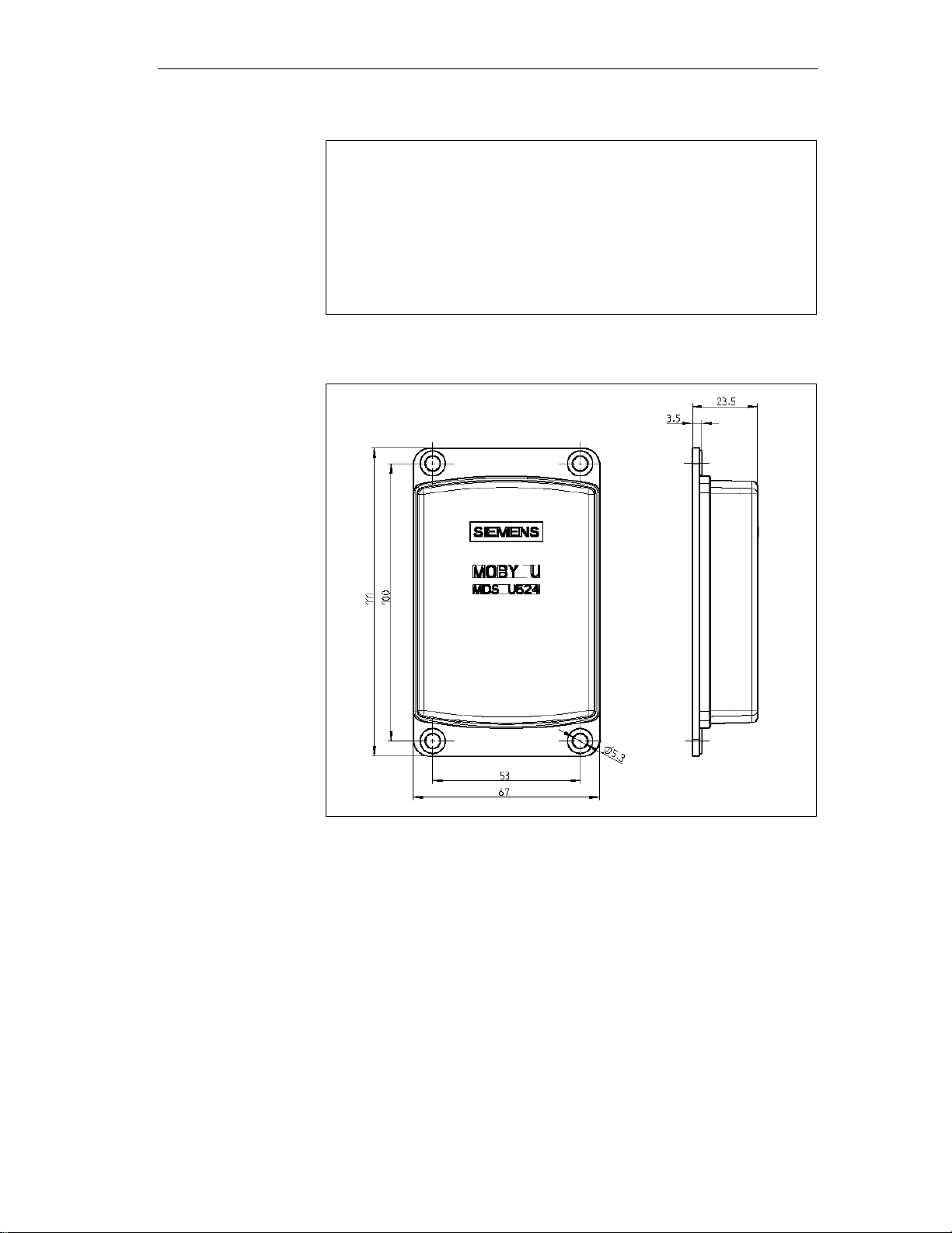
Metal–free space
s
(in mm)
Dimensions (in
mm)
Mobile Data Memorie
Representation of ”metal–free
space”
Figure 4-6 Metal–free space, MDS U524
Figure 4-7 Dimensions of MDS U524
MOBY U – Manual for Configuration, Installation and Service
(4) J31069-D0139-U001-A2-7618
4-11
Page 56
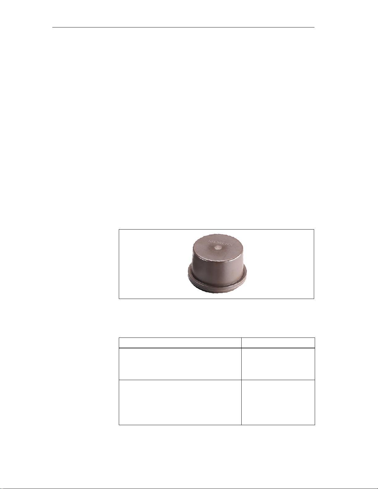
Mobile Data Memorie
s
4.4 MDS U589
The MDS U589 is a mobile data memory (MDS) with a large, 32–Kbyte storage capacity. It is designed for use at high temperature ranges (up to +220
°C, cyclically) especially in the paint shops of the automotive industry. The
size of the MDS permits it to be attached to a skid or directly to a chassis.
The particularly low current consumption guarantees a long life of 5 years.
The interference–immune and robust MDS can be read and written at a maximum distance of 3 m. Addressing the MDS U589 is easy with the filehandler
(from MOBY I) which uses logical file addresses. In addition, the MDS can
also be used with direct memory accessing. The transmission frequency in
the ISM frequency band at 2.4 GHz makes the MDS’s net data transmission
speed very fast (up to 16 Kbyte/sec without multitaging and up to 8 Kbyte/
sec with multitaging of two MDSs).
Some typical applications are listed below.
Basic coat, KTL area, cataphoresis with drying chambers
Covering coat
Ordering data
Washing at temperatures > 85 °C
Other applications with high temperatures
Figure 4-8 MDS U589
Table 4-9 Ordering data of the MDS U589
Mobile data memory MDS U589
With 32–Kbyte RAM
MDS ID number (32 bits)
Read–only memory (128 bits)
Accessories:
Holder
Standard model for MDS U589
Short model for MDS 439E/U589
Long model for MDS 439E/U589
Covering hood for MDS 439E/U589
Order No.
6GT2 500-5JK10
6GT2 590-0QA00
6GT2 090-0QA00
6GT2 090-0QA00-ZA31
6GT2 090-0QB00
4-12
MOBY U – Manual for Configuration, Installation and Service
(4) J31069-D0139-U001-A2-7618
Page 57

Mobile Data Memorie
s
Technical data
Table 4-10 Technical data of the MDS U589
Fixed code memory
Read–only memory 128 bits, to be written once by user
Application memory
Memory technology
Memory size
Memory organization
Data retention time 10 years
MTBF (at +40°C) 2.5 x 10⁶ hours (without conside-
Read/write distance 0.15 m up to 3 m
Depends on direction No
Multitaging capability Yes
Power supply Battery
Battery lifespan 5 years at +25°C 1;
Shock, vibration in acc. w. DIN EN 721-3-7,
class 7 M3
Free fall 1 m
Mounting With holder
Recommended distance from metal Can be mounted directly on metal
Protection rating in acc. w. EN 60529 IP 68
Chemical resistance See table 4-2.
Housing
Dimensions (Ø x H) in mm
Color/material
Ambient temperature
Operation
Transportation and storage
Weight, approx. 600 g
MDS ID number (32 bits)
RAM
32 Kbytes
Byte access; filehandler mode
ring battery)
No replacement
50 g/5 g
114 x 83
Brown/PPS
–25 to +220 °C (cyclic)
–40 to +85 °C
2
1 Lifespan depends on temperature, time MDS is in the SLG’s antenna field (zones 1 and
2) and the amount of read/written data (see chapter LEERER MERKER).
2 Only applies to original holder
MOBY U – Manual for Configuration, Installation and Service
(4) J31069-D0139-U001-A2-7618
4-13
Page 58

Mobile Data Memorie
s
Field data (in mm)
Cyclic operation of
MDS at
temperatures
> 85 C
Table 4-11 Field data of the MDS U589
Standard Minimal Maximal
Working distance (La) 1400 350
Limit distance (Lg) 2000 500
Transmission window (L) 2800 700
Transmission window (W) 2800 700
Minimum distance of MDS to MDS
with
Bunch > 1
Bunch = 1
Directly adjacent
The minimum distance must be such that only
one MDS can be inside the range limit.
The field data apply to reading and writing the MDS. Overranging can be
actively limited by the SLG (in increments of 0.5 m).
At temperatures between 85 °C and 200 °C (briefly at 220 °C), the interior
temperature of the MDS must never be allowed to exceed the critical
threshold of 85 °C. Every heating up phase must be followed by a cooling off
phase. The following tables lists several cycles of the MDS U589 at its
utmost limits.
Metal–free space
(in mm)
Table 4-12 Cycles of the MDS U589at its utmost limits
T
(Heating Up) Heating Up Tu (Cooling Off) Cooling Off
u
200°C 1 h 25 °C > ? h
25 °C > ? h
25 °C > ? h
25 °C > ? h
Siemens will calculate a temperature profile on request.
Representation of ”metal–free
space”
Figure 4-9 Metal–free space, MDS U589
4-14
MOBY U – Manual for Configuration, Installation and Service
(4) J31069-D0139-U001-A2-7618
Page 59

Dimensions
s
(in mm)
1140.5
Mobile Data Memorie
111
111
833
611
7.50.5
Figure 4-10 Dimensions of the MDS U589
MOBY U – Manual for Configuration, Installation and Service
(4) J31069-D0139-U001-A2-7618
4-15
Page 60

Mobile Data Memorie
s
4-16
MOBY U – Manual for Configuration, Installation and Service
(4) J31069-D0139-U001-A2-7618
Page 61

Read/Write Devices
5
MOBY U – Manual for Configuration, Installation and Service
(4) J31069-D0139-U001-A2-7618
5-1
Page 62

Read/Write Devices
5.1 SLG U92
Application area
Setup and
functions
The MOBY U identification system was designed especially for applications
in automotive production, logistics and similar where high demands are
placed on interference immunity, long read/write distances with moving data
memories, quick and reliable data transmission, easy installation, and reliable
function even in rugged environments. It uses the ISM frequency band of 2.4
GHz (familiar world–wide). Its emission strength is way below the values
recommended by well–known health authorities from all over the world.
MOBY U covers a transmission range of up to three meters and thus provides the prerequisites for a transparent identification solution. The SLG is
available for every situation with 2 interface versions.
The primary application areas for MOBY U are listed below.
Main assembly lines of the automotive industry (raw product manufactur-
ing, surface treatment and assembly)
Vehicle identification/entry check for moving companies, vehicle parks,
and so on
Container/pallet identification for transportation logistics and distribution
Traffic control technology
Assembly lines
The SLG U92 handles the commands received from the interface or PC/PLC.
The commands with the data to be read or written are converted into
appropriate communication commands via the HF interface between SLG
and MDS. The amount of data that can be transferred between SLG and MDS
depends on the following factors.
5-2
The speed at which the MDS moves through the SLG’s transmission win-
dow
The length of the transmission window
The number of MDSs in the transmission window (bunch/multitag)
The time during which the MDS is ready for communication (depends on
sleep time and standby time)
The SLG U92 is available in two hardware versions for connection to different systems.
System interface with RS 232
for serial connection to any system
(PC/PLC/communications processors)
System interface with RS 422
for serial connection to MOBY interfaces (ASM 475, ASM 473, ASM
452) for integration in SIMATIC S7 or PROFIBUS or any system (PC/
PLC/communications processors)
MOBY U – Manual for Configuration, Installation and Service
(4) J31069-D0139-U001-A2-7618
Page 63

Read/Write Devices
Except for the system interface, the hardware and firmware of both hardware
versions are identical.
Software tools such as SIMATIC S7 functions (FC 45/FC 46)
and the MOBY API library for applications under Windows 98/NT/2000
make implementation in specific applications easy.
The integrated file management system (compatible with the familiar MOBY
I filehandler and supplemented with multitag commands) ensures simple,
convenient administration of data on the mobile data memories.
The SLG U92 works with a transmission frequency in the ISM band between
2.4 and 2.4835 GHz. This makes transmission distances of up to three meters
possible with a very low sending strength (less than 50 mV per meter at
3-m intervals) and high net transmission speeds of up to 16 Kbyte/sec. By
selection of the transmission frequency, use of robust modulation procedures
and appropriate check routines, sources of electromagnetic interference can
be disregarded and you are still assured of correct data transmission and integrity. MOBY U technology eliminates familiar interference during UHF
transmissions such as reflection, interference and overranging. Specially designed antennas ensure a homogenous transmission field in which mobile
data memories (MDSs) are always (100%) detected. This means expensive
shielding and antenna directing can be omitted. The antenna field of the SLG
can be activated and deactivated for communication with an MDS with a
function call or automatically by triggering a digital input. There are two
ways to manage the data on the mobile data memory.
Byte addressing via absolute addresses (start address, length)
Conveniently with a file management system (compatible with the
MOBY I filehandler)
When the filehandler is used, the MOBY U read/write device always fetches
its file management information directly from the MDS.
The SLG U92 can be run at three levels.
1. MOBY U can be used for existing system solutions with MOBY I with
standard settings, unchanged filehandler functions but without the MOVE
and LOAD commands which used to be required.
2. Only a few extra commands are required for changes in the standard
settings and requesting diagnostic data.
3. Utilization of all features including multitaging. At this level, the
commands and/or user data can also be clearly related to the MDS
number.
Two LEDs show the current status (e.g., communication) and make commissioning easier.
MOBY U – Manual for Configuration, Installation and Service
(4) J31069-D0139-U001-A2-7618
5-3
Page 64
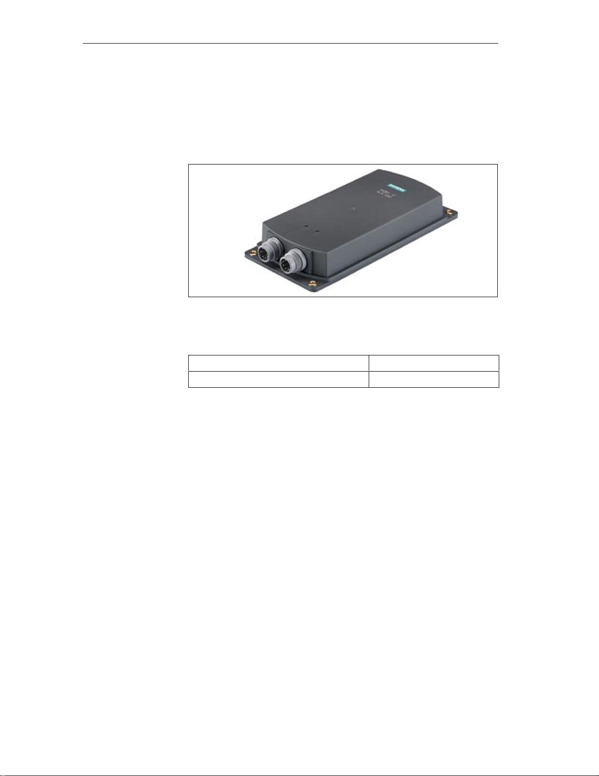
Read/Write Devices
A separate service and diagnostic interface (RS 232) is available for easy
commissioning and diagnosis later during regular operation. In addition, the
service function ”load software to SLG” can be used to load future function
expansions via this interface without having to exchange the SLG in existing
applications.
Figure 5-1 Read/write device SLG U92
Ordering data
Table 5-1 Ordering data of the SLG U92
SLG U92 read/write device with RS 422
SLG U92 read/write device with RS 232 6GT2501-1CA00
6GT2501-0CA00
5-4
MOBY U – Manual for Configuration, Installation and Service
(4) J31069-D0139-U001-A2-7618
Page 65

p()
Maximal
3.0 m
Read/Write Devices
Technical data
Table 5-2 Technical data of the SLG U92
Air interface
Transmission frequency 2.4 to 2.4835 GHz
Band width 2 x 1 MHz within 83 MHz
Gross bit rate of radio channel 384 kbit/sec
Data transmission speed (net) Without bunch With bunch size of 2
Write
Read
Approx. 16.0 Kbyte/sec
Approx. 14.4 Kbyte/sec
Approx. 8.0 Kbyte/s
Approx. 7.2 Kbyte/sec
Range (read/write) 0.15 m up to 3 m
Limit distance (Lg)
Maximal
Minimal
Default
Adjustable via range limitation
3.0 m
0.5 m
1.5 m
Location resolution Range limitation, adjustable in 0.5 m increments
Working distance (La) Approx. 75% of limit distance L
g
Field length/width at Lg = 1.5 m 2 m
Read/write device (SLG)
Functions MOBY filehandler
Direct read/write access
Multi-identification capability Up to 12 MDSs
MDS recording time < 1 sec for 12 MDSs
Object speed < 2 m/sec at L
= 1.5 m and < 2.5 Kbytes of data
a
read/written
Power supply 24 V DC (nominal value), 20 V DC to 30 V DC
Limited Power Source according EN 60 950 /
IEC 60 950
Current consumption (send) < 300 mA
Operating modes (SLG) Standby
Search
Communication
Synchronization, SLG - SLG By semaphore control with 2nd interface; max. of
3 SLGs together
Minimum distance between two
SLGs
> 6 m
Directly adjacent with synchronization
SLG - SLG
MOBY U – Manual for Configuration, Installation and Service
(4) J31069-D0139-U001-A2-7618
5-5
Page 66
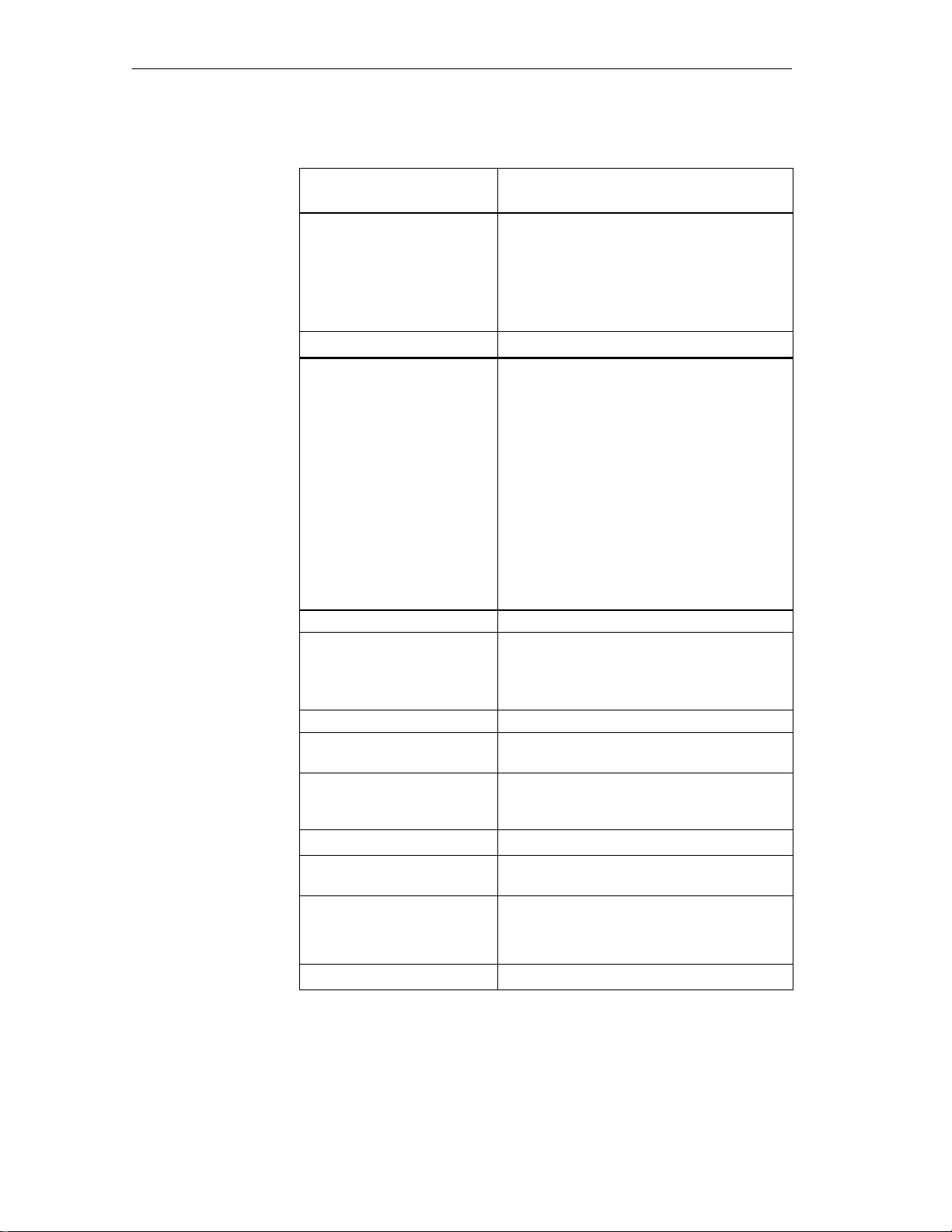
Read/Write Devices
Table 5-2 Technical data of the SLG U92
ASM/PC Interface 6–pin SLG plug in acc. w. EN 175201-804
RS 232 or RS 422 (SLG U92 version)
Transmission speed
Transmission protocol
Line length, SLG - ASM
Line length, SLG - PC
Service interface 11-pin plug in acc. w. EN 175201-804
Interface for service
Transmission speed
Line length, SLG - PC
Transmission protocol
2 DIs for proximity switch
DI 1/DI 2
DI 1 (or DI 2)
Line length, SLG - proximity
switch
Interface for SLG synchronization
Line length, SLG - SLG
Indicator elements 2 LEDs
Housing
Dimensions [L x W x H]
Color
Material
Mounting 4 M6screws
Tightening moment (at room
temperature)
Shock, vibration in acc. w. DIN
EN
721-3-7, class 7 M3
MTBF (at +40 °C) 2 x 10⁶ hours
Protection rating in acc. w. EN
60529
Ambient temperature
Operation
Transportation and storage
Weight, approx. 900 g
Automatic baud rate recognition, 19.2 to 115.2
KBaud (depends on ASM/PC and/or line length)
3964 R
Max. of 1000 m (RS 422; shielded)
Max. of 30 m (RS 232; shielded)
RS 232
19.2 KBaud
Max. of 30 m
Terminal, ASCII characters
Proximity switch for trigger antenna field, on/off
Proximity switch for antenna field duration, on
Max. of 50 m
Max. of 30 m
290 x 135 x 42 without plug
Anthracite
Plastic, PA 12 GF 25
2 Nm
30 g/1.5 g
IP 65
–25 to +70 °C
–40 to +85 °C
5-6
MOBY U – Manual for Configuration, Installation and Service
(4) J31069-D0139-U001-A2-7618
Page 67

Read/Write Devices
Table 5-2 Technical data of the SLG U92
Antenna Integrated in the SLG
Emission
Emission density
Angle of opening Approx. 90 ° horizontal/vertical
Polarization Circular
Certifications BAPT (ETS 300 440), FCC (15.249)
< 50 mV per meter at 3-m intervals
2
< 0.5 mW/cm
CE (ETS 300 683), UL, CSA
Safe for pacemakers
(at distance of 1 m)
Field data
Transmission
window
Metal–free space
(in mm)
The field data are the same regardless of MDS type.
Table 5-3 Technical data of the SLG U92
Working distance (L
Limit distance (Lg)
Transmission window L
Minimum distance D from SLG to SLG
Figure 5-2 Transmission window of the SLG U92
) 150 to
a
Presentation of ”transmission window”
Figure 5-3 Metal–free space of SLG U92
MOBY U – Manual for Configuration, Installation and Service
(4) J31069-D0139-U001-A2-7618
Representation of ”metal–free
space”
5-7
Page 68

Read/Write Devices
Definition distance
D
Dimensions (in
mm)
Presentation of ”definition of distance D”
Figure 5-4 Distance D: SLG U92
135
110
42
6
290
270
∅6.5
4.7
42
Service interface T o ASM/PC
Figure 5-5 Dimensional drawing of the SLG U92
23.2
5-8
MOBY U – Manual for Configuration, Installation and Service
(4) J31069-D0139-U001-A2-7618
Page 69

Interfaces
6
MOBY U – Manual for Configuration, Installation and Service
(4) J31069-D0139-U001-A2-7618
6-1
Page 70

Interfaces
6.1 Introduction
Application area
The ASM interfaces are the link between the MOBY U components
(SLGs/MDSs) and the high–level controllers (e.g., SIMATIC S7) or PCs or
computers. Depending on the interface used, up to two SLGs can be
connected.
Setup and
functions
An ASM consists of a microcontroller system with its own program (PROM).
The CPU receives the commands over the user interface and stores these in
the RAM. The user receives an acknowledgment that the command has
arrived. If the command is okay, the CPU begins executing it.
Overview
Table 6-1 Overview of the interfaces
ASM
Type
ASM 452 PROFIBUS-
ASM 473 Can be plug-
ASM 475 Can be plug-
Interfaces
to PC/
Computer
DPV1
ged into
ET 200X
ged into
S7-300/
ET 200M
Interfaces
to SLG
2 x 5–pin
prox. switch
plug
2 x 5–pin
prox. switch
plug
Via screw
terminals
Function
Blocks
FC 45
FC 46
FC 56
FC 45
FC 56
FC 45
FC 56
SLG
Connec-
tions
1 134 x 110 x 55 0 to +55 °C IP 67
1 87 x 110 x 55 0 to +55 °C IP 67
2
(parallel)
Dimensions
(W x H x D in
mm)
40 x 125 x 120 0 to +60 °C IP 20
Temperature
Range
(Operation)
Protect
ion
Rating
6-2
MOBY U – Manual for Configuration, Installation and Service
(4) J31069-D0139-U001-A2-7618
Page 71

6.2 ASM 452
Interfaces
Application area
The ASM 452 interface is a MOBY module for use with MOBY components
via PROFIBUS–DPV1 on the following devices.
All computers and PCs
All controllers
When the interfaces are used with a SIMATIC S7, function blocks are available to the user.
Figure 6-1 Interface ASM 452
The ASM 452 represents the further development of the familiar 450/451
interface modules. By using non–cyclic data communication on PROFIBUS–
DPV1, even the most extensive PROFIBUS configurations have optimum
data throughput. The minimum cyclic data load of the ASM 452 on PROFIBUS guarantees the user that other PROFIBUS stations (e.g., DI/DO) will
continue to be processed very quickly.
The ASM 452 is an interface module for communication between PROFIBUS and the SLG U92 with RS 422. The data on the MDS U313/524/589can
be addressed with the ASM 452 in the following ways.
Physical addressing (”normal” addressing) or
With a filehandler similar to DOS
The SIMATIC S7 offers FCs for the two methods of access.
FC 45 for ”normal” addressing
FC 46 for filehandler without multitaging. FC 56 for filehandler with
multitaging.
FC 45 and FC 46/56 give the S7 user an easy–to–use interface with powerful
commands. FC 45 and FC 56 offer additional command chaining and S7 data
structures via UDTs.
MOBY U – Manual for Configuration, Installation and Service
(4) J31069-D0139-U001-A2-7618
6-3
Page 72

Interfaces
Ordering data
Table 6-2 Ordering data of the ASM 452
Interface ASM 452
for PROFIBUS-DPV1
can be connected with 1x SLG U92 with
RS 422
Accessories:
Plug connector for PROFIBUS–DP connec-
tion and 24 V power
SLG cable ASM 452 SLG
Length 2 m; standard cable
Other lengths: 5 m, 10 m, 20 m and 50 m
Opt. conn. plug without SLG cable
(for cable lengths > 20 m)
ASM 452 SLG
M12 covering caps for unused SLG connections (1 package = 10 each)
MOBY software
1)
with FC 46, FC 45, FC 56, GSD file
Replacement part:
Plug connector plate; T design for PROFIBUS connection
6GT2 002-0EB20
6ES7 194-1AA00-0XA0
6GT2 091-1CH20
6GT2 091-1C...
6GT2 090-0BC00
3RX9 802-0AA00
6GT2 080-2AA10
6ES7 194-1FC00-0XA0
Description of FC 45 (for ASM 452)
deutsch
English
Description of FC 46 (for ASM 452)
deutsch
English
Description of FC 56
1) See chapter .7.1
6GT2 097-3AM00-0DA1
6GT2 097-3AM00-0DA2
6GT2 097-3AC40-0DA1
6GT2 097-3AC40-0DA2
6-4
MOBY U – Manual for Configuration, Installation and Service
(4) J31069-D0139-U001-A2-7618
Page 73

PROFIBUS
Technical data
Interfaces
Table 6-3 Technical data of ASM 452
ASM 452
with FC 45
Serial interface to user PROFIBUS-DPV1
Procedure after connection EN 50170, vol. 2, PROFIBUS
PG 11 screw connection
and power supply plugs are not included.
Transmission speed
Max. block length 2 words (cyclic)/240 bytes (non–cyclic)
Serial interface to SLG
Plug connector
Line length, max.
SLGs which can be connected
Software functions
Programming Depends on PROFIBUS-DP master
Function blocks for
SIMATIC S7
MDS addressing Direct access with ad-
9600 Baud to 12 Mbaud (automatic detection)
2 M12 coupling plugs
2 m = standard length;
Other prefabricated cables: 5 m, 10 m, 20 m,
50 m (up to 1000 m on request)
1x SLG U92 with RS 422
FC 45 FC 46 FC 56
dresses
ASM 452
with FC 46
Access via logical file names
(file system similar to DOS)
ASM 452
with FC 56
Commands Initialize MDS, read
Multitag capability No No Yes
S7 data structures via UDT s Yes No Yes
Voltage
Nominal value
Permissible range
Current consumption
Digital inputs None
Digital outputs None
Ambient temperature
Operation
Transportation and storage
Dimensions (W x H x D) inmm134 x 110 x 55 (without bus plug)
MOBY U – Manual for Configuration, Installation and Service
(4) J31069-D0139-U001-A2-7618
Format MDS, read file, write
data from MDS, write
data to MDS, and so on
24 V DC
20 to 30 VDC
Max. of 180 mA; typ. 130 mA
(without SLG, DO not loaded)
0 to +55 °C
–40 to +70 °C
file, and so on
6-5
Page 74

Interfaces
Table 6-3 Technical data of ASM 452
ASM 452
with FC 45
Mounting 4 M5 screws;
Mounting on all plates or walls
Weight, approx. 0.5 kg
Protection rating IP 67
MTBF (at 40 °C) 30 x 104 hours = 34 years
PROFIBUS-DP
master module
(e.g., S7-400 CPU)
PROFIBUS line
24 V
for
To other
PROFIBUS stations
SLG
ASM 452
with FC 46
AT-comp. PC
ASM 452
with FC 56
*
2 m
Hardware
description
PROFIBUS
configuration
SLG
* Standard cable lengths
MDS
Figure 6-2 Configurator – ASM 452
The ASM 452 has the same housing as the distributed I/O device ET 200X.
For the general chapters on the ASM 452 (e.g., mounting, operation and
wiring, general technical data) see the ET 200X manual (order no. 6ES7
198-8FA00-8AA0). Accessories and network components are also covered by
this manual.
The ASM 452 is integrated in the hardware configuration with a GSD file.
The ASM is then configured with HW Config of SIMATIC Manager or
another PROFIBUS tool. ”MOBY software” contains a GSD file for the
ASM 452.
6-6
MOBY U – Manual for Configuration, Installation and Service
(4) J31069-D0139-U001-A2-7618
Page 75

Interfaces
SLG connection
technology
An SLG always occupies two M12 connection sockets on the ASM 452. A
prefabricated cable (cf. figure 6-4) makes it very easy to connect the SLG.
The standard version of the connection cable has a length of 2 m. Other
available lengths are 5 m, 10 m, 20 m and 50 m.
An SLG connection plug with screw terminals is available for users who
want to make their own cables (see figure 6-3). Cables and SLG connection
plugs can be ordered from the MOBY catalog.
Plug covering hood removed
1
2
3
4
Core
Color
Green
White
Brown
Yellow
Gray
Pink
- (nc)
Shield
Connection to
Pin of SLG
Plug
5
6
S
S
4
6
1
5
3
2
-
48
18.5
Protection rating IP 67
SLG cable: 6GT2 090-0A
PG 11 screw;
Max. cable diameter = 6.5 mm
(Don’t tighten screw until plug is
assembled.)
2 screws to
open the plug
Coupling plug M12
on ASM 452
Plug Pin
1
2
3
4
5
6
S
S
Figure 6-3 Connection plug for ASM 452, 473 SLG U92 with RS 422
(6GT2 090-0BC00)
Two 5–pin, round M12
plug connectors
22.5
18.5
x1
* Standard length
X2
X1/2
X1/3
X1/1
X1/4
X2/3
X2/1
X1/5
X2/5
2 m *
White
Brown
Green
Yellow
Gray
Pink
SLG plug (socket)
6
1
4
5
3
2
Figure 6-4 Connection cable for ASM 452, 473 SLG U92 with RS 422
(6GT2 091-1CH20)
MOBY U – Manual for Configuration, Installation and Service
(4) J31069-D0139-U001-A2-7618
6-7
Page 76
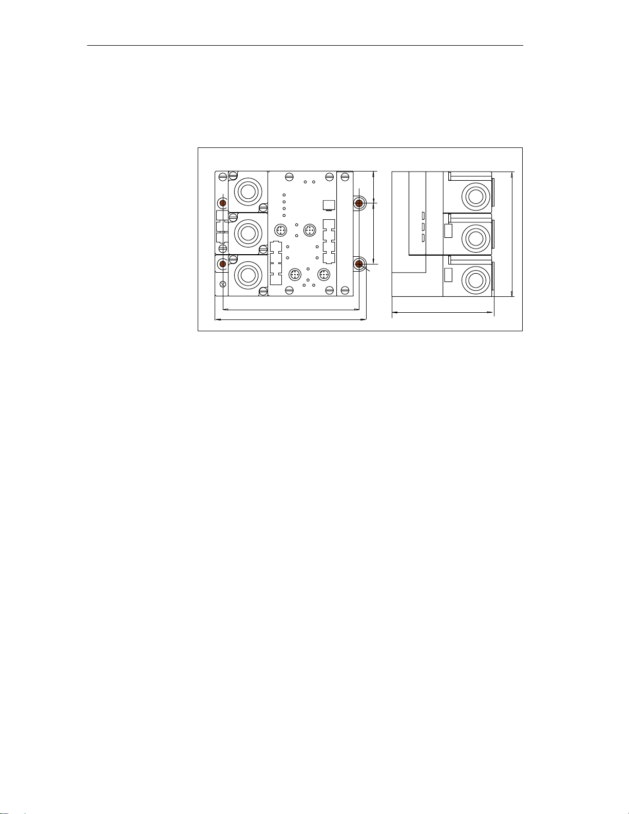
Interfaces
Dimensional
drawing
The following diagram shows a dimensional drawing of the ASM 452 with
bus connection plugs. The length of the PG screws and the radius of the cable
must both be added to the total width and depth specified below.
28.25
53.5
Ø 5.5
120
134
Figure 6-5 Dimensional drawing of the ASM 452
90
110
6-8
MOBY U – Manual for Configuration, Installation and Service
(4) J31069-D0139-U001-A2-7618
Page 77

Interfaces
Pin allocations
X11
1
X12
1
X13
1
Socket
X11 and X12
(PROFIBUS-DP)
X13
(power supply)
The figure below shows the pin allocations of the ASM 452.
LEDs for PROFIBUS-DP
SF: System Fault (hardware error on ASM)
654
SF
32
654
32
654
32
BF
ON
24 V DC
SLG1
x1
123
RxD
5
4
ERR
DE0 DE1
x3
SLG2
RxD
Not available for MOBY U
Pin Allocation
1 Signal B
2PE
3* PE
4 Signal A
5* L+
6* M
1PE
2L+
3M
4PE
5L+
6M
X2
ANW
x4
BF: Bus Fault (fault on PROFIBUS-DP)
ON: On when the logic voltage is present on
the ASM 452 (is generated from 24 V
power)
24 V DC: On when 24 V is connected to
ASM 452
LEDs for MOBY
RxD: Communication with SLG active
ANW: MDS present
ERR: Error indicator
All other LEDs are not assigned.
Socket
X1/X3
Pin Allocation (SLG)
1 +RxD
2 +TxD
3 -TxD
4 -RxD
5PE
X2
1 +24 V
2 Res.
30 V
4 Res.
5PE
* Don’t circuit
Figure 6-6 Pin allocation and LEDs of the ASM 452
MOBY U – Manual for Configuration, Installation and Service
(4) J31069-D0139-U001-A2-7618
6-9
Page 78

ООООО
ООООО
Interfaces
Example of how
much cable to bare
PROFIBUS
address and
terminating
resistance
The following figure shows an example of how to bare a cable. The lengths
apply to all cables which you can connect to the connection plugs. Twist
existing shield braiding, stick in a core sleeve, and trim off excess.
45
Twisted and trimmed
shield braiding
6
Figure 6-7 Length of bared cable for PROFIBUS cable
The plug connector plate of the ASM must be removed before you can set the
PROFIBUS address or turn on the terminating resistance. The plug connector
plate covers the DIP switches. The following figure shows the location of the
DIP switches on the ASM and the applicable sample setting.
Example:
Terminating resistance on (status on delivery)
ON
OFF
Example: PROFIBUS address 120 (status on delivery)
23 +24 + 25 + 26 = 8 + 16 + 32 + 64 = 120
ON
Figure 6-8 Setting PROFIBUS address/turning on terminating resistance
Note
The PROFIBUS address on the ASM 452 must always be the same as the
PROFIBUS address specified for this ASM in the configuration software.
You must always turn both DIP switches to ”on” or to ”off” so that the
terminating resistance is correct.
Res.
8
Filehandler
7654321
6-10
MOBY U – Manual for Configuration, Installation and Service
(4) J31069-D0139-U001-A2-7618
Page 79

6.3 ASM 473
Interfaces
Application area
The ASM 473 interface is a MOBY module for the SIMATIC S7. It can be
connected to the distributed I/O device ET 200X and DESINA.
PROFIBUS–DPV1 serves as the interface to the user when the ET 200X is
used. An S7–300 or S7–400 with integrated PROFIBUS connection can be
used as the controller.
The ASM 473 supplements the SIMATIC S7 MOBY interface module ASM
475. With its protection rating of IP 67, it can be set up and operated directly
within the process without an extra protective case.
An ET 200X basic module (BM 141/142) with the order number
6ES7 141-1BF11-0XB0 or 6ES7 142-1BD21-0XB0 or a BM 143 is a prerequisite for using the ASM 473.
The data are accessed on the MDS with physical addresses.
Function FC 45 is available for operation on a SIMATIC S7. The hardware
configuration of the ASM 473 is performed with an Object Manager (OM)
which is integrated in SIMATIC Manager.
Other features
Up to 7 ASM 473s can be run in parallel on one ET 200X station.
All I/O modules from the ET 200X family can be run parallel to the ASM
473.
Figure 6-9 Interface ASM 473
MOBY U – Manual for Configuration, Installation and Service
(4) J31069-D0139-U001-A2-7618
6-11
Page 80

Interfaces
Ordering data
Technical data
Table 6-4 Ordering data of the ASM 473
Interface ASM 473
1x SLG U92 with RS 422 can be connected
Accessories:
SLG cable, ASM 473 SLG
Length 2 m; standard cable
Other lengths: 5 m, 10 m, 20 m and 50 m
Opt. conn. plug without SLG cable (for cable
lengths > 20 m)
ASM 473 SLG
MOBY Software
with FC 45, GSD file
Description of FC 45 (for ASM 473)
deutsch
English
1 See chapter 7.1.
Table 6-5 Technical data of the ASM 473
1
6GT2 002-0HA00
6GT2 091-1CH20
6GT2 091-1C...
6GT2 090-0BC00
6GT2 080-2AA10
6GT2 097-3AM00-0DA1
6GT2 097-3AM00-0DA2
Interface to the ET 200X
Communication
Command buffer on ASM
Serial interface to SLG
Plug connector
Line length, max.
SLGs which can be connected
Software functions
Programming
Function blocks for SIMATIC S7
MDS addressing
Commands
PROFIBUS diagnosis
S7 diagnosis
Firmware can be loaded.
SIMATIC S7 P bus,
cyclic/non–cyclic services
2 words (cyclic)/
238 bytes (non–cyclic)
142 x 238 bytes
2 M12 coupling plugs
2 m = standard length;
Other prefabricated cables = 5 m,
10 m, 20 m, 50 m
(up to 1000 m on request)
1x SLG U92 with RS 422
Depends on PROFIBUS-DP master
FC 45
Direct access with addresses
Initialize MDS, read data from
MDS, write data to MDS, and so
on
Yes, in acc. w. ET 200X basis station
Yes, can be called via S7 OEM
Yes, via S7 OEM
6-12
MOBY U – Manual for Configuration, Installation and Service
(4) J31069-D0139-U001-A2-7618
Page 81

Interfaces
Table 6-5 Technical data of the ASM 473
Voltage
Nominal value
Permissible range
Current consumption
Power loss of the module
Digital inputs/outputs Via expansion modules from the
Ambient temperature
Operation
Transportation and storage
Dimensions (W x H x D) in mm
Single device
Scaling interval
Mounting
Protection rating
Weight, approx.
24 V DC
20.4 V to 28.8 V DC
Typ. 75 mA; max. of 500 mA (or
see technical data of your SLG)
1.6 W (typical)
ET 200X family
0 °C to +55 °C
–40 °C to +70 °C
87 x 110 x 55
60 x 110 x 55
2 M5 screws (supplied by custo-
mer)
2 M3 screws (supplied by device)
IP 67
0.275 kg
For information on setup and other general technical data, see the ET 200X
manual (order number 6SE7 198-8FA01-8AA0).
MOBY U – Manual for Configuration, Installation and Service
(4) J31069-D0139-U001-A2-7618
6-13
Page 82

Interfaces
Configuration
PROFIBUS
to all
PROFIBUS slaves
PROFIBUS-DP master module
(e.e., S7-400 CPU)
(Connection of master of other mfg
being prepared)
2 m (standard cable length)
24 V power for ET
200X electronics and
MOBY SLG
Figure 6-10 Configurator for an ASM 473
Note
The ET 200X differs from the ASM 452 (see figure 6-2) in that the 24 V
must be fed to the PROFIBUS plug and the load voltage plug (see ET 200X
manual for more information).
Basis module:
ET 200X; BM 141
ET 200X; BM 142
DESINA; BM 143
SLG
MDS
6-14
MOBY U – Manual for Configuration, Installation and Service
(4) J31069-D0139-U001-A2-7618
Page 83

A max. of 7 ASM 473s can be operated in one ET 200X.
Interfaces
Figure 6-11 Maximum configuration of ASM 473s on one ET 200X
Depending on the PROFIBUS master, up to 123 ET 200X modules can be
operated on one PROFIBUS branch.
Hardware
configuration
The ASM 473 is integrated in the hardware configuration of SIMATIC
Manager by calling Setup.exe in the directory S7_OM\ASM473_OM on the
”MOBY Software” CD. At the moment the ASM 473 cannot be integrated on
the master of another manufacturer.
SLG connection
technology
An SLG always occupies two M12 connection sockets (X3 and X4) on the
ASM 473. A prefabricated cable (cf. figure 6-4) makes it very easy to
connect the SLG. The standard version of the connection cable has a length
of 2 m. Other lengths are available on request. An SLG connection plug with
screw terminals (see figure 6-3) is available for users who want to make their
own cables. Cables and SLG connection plugs can be ordered from the
MOBY catalog.
MOBY U – Manual for Configuration, Installation and Service
(4) J31069-D0139-U001-A2-7618
6-15
Page 84

Interfaces
Pin allocations
The following figure shows the pin allocation to the SLG and describes the
indicator elements.
Socket Pin Allocation (SLG)
1
x3
x4
LEDs for PROFIBUS-DP
General operational indicators (SF, BF, ON, 24 V DC) are located on the
basic module of the ET 200X.
LEDs for MOBY
RxD: SLG is active with a command.
PRE: Indicates the presence of an MDS
ERR: Error indicated by flashing pattern (see chapter B.1)
+RxD
2
+TxD
3
–TxD
4
–RxD
5
PE
1
+24 V
2
n. c.
3
0 V
4
n. c.
5
PE
The PRE and ERR LEDs indicate other operational states of the ASM.
PRE
OFF/ON
ON
2 Hz
ERR
ON (perm.)
OFF
OFF
Description, Causes, Remedies
Hardware is defective (RAM, Flash, etc.).
Loader is defective (can only be fixed at the plant).
Firmware loading procedure is active or no
firmware detected
→ Load firmware.
→ Don’t turn off ASM during this.
2 Hz
2 Hz
Firmware load terminated with error
→ New start is required.
→ Load firmware again.
→ Check update files.
5 Hz
5 Hz
Operating system error
→ Turn ASM or ET 200X basis station
off/on.
OFF
1 flash
every 2
ASM has started up and is waiting for a RESET
(init_run) from the user.
sec
Figure 6-12 Pin allocation and LEDs of the ASM 473
6-16
MOBY U – Manual for Configuration, Installation and Service
(4) J31069-D0139-U001-A2-7618
Page 85

Interfaces
Dimensional
drawing of
mounting holes
The figure below shows the dimensions for the positions of the holes for the
mounting screws for one basic module and one ASM 473 expansion module.
28.25
53.5
110
120
126.8
BM 141/142 ASM 473
n = number of expansion modules
Figure 6-13 Dimensions for mounting holes for basic and expansion modules
n 60
87
For M5 mounting
screw
MOBY U – Manual for Configuration, Installation and Service
(4) J31069-D0139-U001-A2-7618
6-17
Page 86

Interfaces
6.4 ASM 475
Application area
The ASM 475 interface module is a MOBY module which can be installed
on the SIMATIC S7–300 and ET 200M.
Up to eight ASM 475 interface modules can be installed and run in one module rack of the SIMATIC S7–300. When a setup with several module racks
(max. of four) is used, the ASM 475 can be installed and run in every rack. In
its maximum configuration, one SIMATIC S7–300 can handle up to 32
ASMs centrally. The ASMs can just as well be run on the distributed I/O ET
200M on PROFIBUS. This makes operation in an S7–400 environment possible. Up to 7 ASMs can be run on one ET 200M.
Error messages and operational states are indicated with LEDs. The galvanic
isolation between SLG and the SIMATIC S7–300 bus permits interference–
immune operation.
Figure 6-14 Interface ASM 475
The ASM 475 is an interface module for communication between the
SIMATIC S7 and the SLG U92 with RS 422. The data on the MDS
U313/524/589can be addressed with the ASM 475 in the following ways.
Physical addressing (”normal” addressing) or
With a filehandler similar to DOS
The SIMATIC S7 offers a function for each of the two methods of access.
FC 45 for ”normal” addressing
FC 56 for Filehandler
FC 45 and FC 56 give the S7 user an easy–to–use interface with powerful
commands. FC 45 and FC 56 offer additional command chaining and S7 data
structures via UDTs.
6-18
MOBY U – Manual for Configuration, Installation and Service
(4) J31069-D0139-U001-A2-7618
Page 87

ASM 475
Interfaces
Ordering data
Shield connection terminal
(6ES7 390-5BA00-0AA0)
SLG SLG
MDS MDS
Figure 6-15 Configurator for an ASM 475
Table 6-6 Ordering data for ASM 475
Interface ASM 475
for SIMATIC S7
2 x SLG U92 with RS 422 can be connected parallel, without front plug connector
Accessories:
Front plug connector (1 per ASM)
Shield connecting element
(6ES7 390-5AA00-0AA0)
for 2 modules
6GT2 091-0E...
6GT2 002-0GA00
6ES7 392-1AJ00 -0AA0
SLG cable, ASM 475 SLG
Lengths: 2 m, 5 m, 10 m, 20 m and 50 m
Optional: SLG cable, ASM 475 → SLG
with straight SLG plug
Shield connection terminal (1 per SLG cable)
Shield connecting element
MOBY Software
1)
with FC 45, FC 56, S7 Object Manager
Description of FC 45 (for ASM 475)
deutsch
English
Description of FC 56 (for ASM 475)
deutsch
English
1) See chapter .7.1.
MOBY U – Manual for Configuration, Installation and Service
(4) J31069-D0139-U001-A2-7618
6GT2 091-0E...
6GT2 091-2E...
6ES7 390-5BA00 -0AA0
6ES7 390-5AA00 -0AA0
6GT2 080-2AA10
6GT2 097-3AM00-0DA1
6GT2 097-3AM00-0DA2
6-19
Page 88

Interfaces
Technical data
Table 6-7 Technical data of the ASM 475
ASM 475 with FC 45 ASM 475 with FC 56
Serial interface to
SIMATIC S7-300 or
ET 200M
Communication
Command buffer on ASM
475
Serial interface to SLG
Plug connector With screw terminal on front plug connector
Line length, max. Prefabricated cables = 2 m, 5 m, 10 m,
SLGs which can be connected
Software functions
Programming Depends on PROFIBUS-DP master
Function blocks for
SIMATIC S7
MDS addressing
P bus; cyclic and non–cyclic services
2 words (cyclic)/238 bytes (non–cyclic)
142 x 238 bytes per SLG U92
The front plug connector is included.
50 m (up to 1000 m on request)
2x SLG U92 with RS 422
Parallel operation
FC 45
Access directly via addresses
FC 56
Access via logical
file names (file system similar to DOS)
Commands
Multitag mode
S7 data structures with UDT s
Voltage
Nominal value
Permissible range
Current consumption
Without SLG at U =
24 V DC, max.
With connected SLGs,
max.
Power loss of the module(typ.)
Current consumption from P
bus, max.
Potential isolation between
S7-300 and MOBY
24 V fuse to SLG
Initialize MDS, read data
from MDS, write data to
MDS, and so on.
No
Yes
24 V DC
20.4 to 28.8 VDC
350 mA
500 mA, per connected SLG
2 W
80 mA
Yes, use own power pack for ground–free operation
for the ASM 475
Yes, electronic
Format MDS,
read file,
write file, etc.
Yes
Yes
6-20
MOBY U – Manual for Configuration, Installation and Service
(4) J31069-D0139-U001-A2-7618
Page 89

Ambient temperature during
operation
Horizontal setup of SI-
MATIC
Vertical setup of SIMA-
TIC
Transportation and storage
Dimensions (W x H x D) inmm40 x 125 x 120
Weight, approx. 0.2 kg
0 to +60 °C
0 to +40 °C
–40 to +70 °C
Wiring The ASM 475 is commissioned in the following steps.
Mount module
Mount module on profile rail of the S7–300
(see manual of the S7-300)
Interfaces
ASM 475 with FC 56ASM 475 with FC 45
Note
Before mounting the module, switch the CPU of the S7–300 to STOP.
Warning
!
Wire the S7–300 only when the power is off.
Note
To ensure interference–free operation of the ASM 475, make sure that ASM
and SIMATIC CPU (or ASM and IM 153 with ET 200M operation) use the
same voltage.
If not, error indicators which light up on the CPU when the ASM is turned
on may not go off.
MOBY U – Manual for Configuration, Installation and Service
(4) J31069-D0139-U001-A2-7618
6-21
Page 90

Interfaces
Front plate The following figure shows the front plate of the ASM 475 and the inside of
the front door with the connection diagram. The SLGs must be connected
with the ASM as shown in the connection diagram.
MOBY
ASM475/6
SF
DC5 V
ACT_1
ERR_1
PRE_1
RxD_1
ACT_2
ERR_2
PRE_2
RxD_2
S+
S–
E+
E–
S+
S–
E+
E–
SLG 1
SLG 2
6GT2 002-0GA10
Status and error indicators
Connection diagram
The numbers for the
connection refer to plug
connector X1 of the
upper portion of the
housing.
Figure 6-16 Front plate and inside of the front door of the ASM 475
6-22
MOBY U – Manual for Configuration, Installation and Service
(4) J31069-D0139-U001-A2-7618
Page 91

y
E
2
A flashi
PRE_1, PRE_2
Shows the presence of an MDS;
Indicator elements
on the ASM
Interfaces
Table 6-8 Function of the LEDs on the ASM 475
Meaning
SF
5V DC
ACT_1, ACT_2
rror_1, Error_
PRE_1, PRE_2
RxD_1, RxD_2
LED
System Fault (hardware error on ASM)
24 V are connected on ASM and the 5 V
on the ASM are okay.
The SLG is active with execution of a
user command.
ng pattern shows the error that occurred last. This indicator can be reset
with the parameter Option_1.
Shows the presence of an MDS;
Indicates running communication with the
SLG; interference on SLG can also cause
this indicator to go on.
The LEDs PRE, ERR and SF on the ASM 475 indicate additional operating
states.
Table 6-9 Operating states shown by LEDs on the ASM 475
SF
ON
ON
PRE_1 ERR_1 PRE_2 ERR_2 Meaning
OFF/ON
OFF
ON
(perm.)
ON
OFF/ON
OFF
ON
(perm.)
OFF
Hardware is defective
(RAM, Flash, etc.).
Loader is defective (can
only be fixed at the plant).
OFF
OFF 2 Hz 2 Hz 2 Hz 2 Hz Firmware loading termina-
Any 5 Hz 5 Hz 5 Hz 5 Hz Operating system error
OFF OFF 1 flash
2 Hz
OFF
every 2
sec
2 Hz
OFF 1 flash
OFF
every 2
sec
Firmware loading procedure is active or no firmware was detected.
– Load firmware.
– Don’t turn off
ASM during this.
ted with error
– New start required
– Load firmware
again.
– Check update files.
– Turn ASM off/on.
ASM has started up and is
waiting for a RESET
(init_run) from the user.
MOBY U – Manual for Configuration, Installation and Service
(4) J31069-D0139-U001-A2-7618
6-23
Page 92
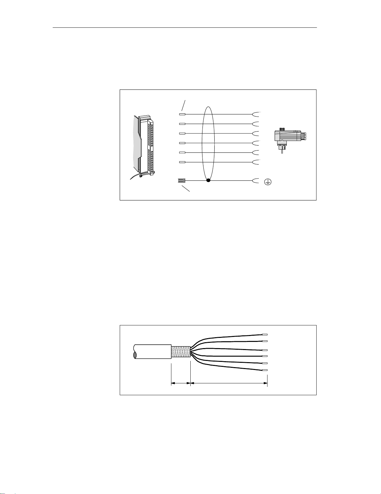
Interfaces
Wiring to the SLG
Shield connection
The following figure shows the design of a connection cable between ASM
and SLG. The specified colors apply to the standard MOBY cable for the
ASM 475.
Front plug
of the ASM
(6ES7 392-1AJ00-0AA0)
4 (12)
5 (13)
6 (14)
7 (15)
8 (16)
9 (17)
Figure 6-17 Wiring of the ASM 475 to the SLG U92 with RS 422 (6GT2 091-0E...)
Cable with core sleeves
White
Brown
Green
Yellow
Pink
Gray
(Shield)
Cable shield open
SLG – plug
(socket)
6
1
4
5
2
3
See figure 3-12 or 6-15.
Lightning rods
Cable fabrication
by the customer
Implement lightning rods and grounding measures if required for your
application. Protection against lightning always requires an individual look at
the entire plant.
To ensure EMC, the SLG cable must be led over an S7–300 shield
connecting element (see figure 6-15). When customers make their own
cables, the shield of the SLG cable must be bared as shown in figure 6-18.
30 170
Specifications in mm
Figure 6-18 Baring of the cable shield for customer–fabricated cable
6-24
MOBY U – Manual for Configuration, Installation and Service
(4) J31069-D0139-U001-A2-7618
Page 93

Configuration of
the ASM for
SIMATIC S7 under
STEP 7
Interfaces
Note
Installation of MOBY requires functional STEP 7 software on a PC/PG.
Please remember to use the latest version of STEP 7. At the moment, you
will need STEP 7 V 5.1 Service Pack 3 for MOBY U operation.
Installation and configuration of the ASM 475 in the SIMATIC is performed
with an installation program. The installation program is included on the
”MOBY Software” product (6GT2 080-2AA10).
Installation
The installation files are located in subdirectory S7_om on the MOBY
software CD. Most of the installation is automatic after Setup.exe is called.
The specified steps during SETUP must be answered.
See the ASM 475 module in the hardware catalog of HW Config in the following subdirectory for hardware configuration of the SIMATIC S7.
SIMATIC 300
SM 300
Special 300
MOBY ASM470
MOBY ASM475
MOBY ASM476
Figure 6-19 ASM 475 directory in the hardware catalog
MOBY U – Manual for Configuration, Installation and Service
(4) J31069-D0139-U001-A2-7618
6-25
Page 94

Interfaces
FC 45/56 with
sample project
You can use the ”file dearchivation” function of SIMATIC Manager to load
the FC with a sample project from the applicable subdirectory of ”MOBY
Software.” The sample project is located in the S7PROJ directory of
SIMATIC Manager.
Directory in MOBY Software
FC 45 MOBY FC45 Moby_f_l
FC 56*
* Under preparation
Project Name in SIMATIC
Manager
Path Name in SIMATIC
Manager
6-26
MOBY U – Manual for Configuration, Installation and Service
(4) J31069-D0139-U001-A2-7618
Page 95

Accessories
7
MOBY U – Manual for Configuration, Installation and Service
(4) J31069-D0139-U001-A2-7618
7-1
Page 96

Accessories
7.1 MOBY Software
The ”MOBY Software” product is delivered on CD. It contains all function
blocks and drivers for the MOBY system. The software components and their
documentation are described briefly in the file ”Read_me.txt” in the main
directory of the CD.
The software components on the CD which are relevant to MOBY U are
listed below.
FC 45
SIMATIC S7 function for ASM 452 / 473 / 475
FC 46
SIMATIC S7 function for ASM 452
FC 56 for ASM 452/473/475
MOBY_lib MOBY API
MOBY API application interface with the 3964R driver for
Windows 98/2000/NT 4.0
1
Manuals
Current status of MOBY documentation in PDF format
S7-om
Installation program and Object Manager for interface modules ASM 473
and ASM 475
Sample projects are installed here with the appropriate FCs. These are
located in the applicable FC directories.
Demo
Test and demo programs for PC with Windows 98/2000/NT 4.0
Tools
Useful programs for MOBY configuration are located here.
Short descriptions of the individual directories in German or English (cf.
“Les_mich.txt” or “Read_me.txt”).
Profi_gsd
PROFIBUS master device files for ASM 452
Only the components related to MOBY U are specified from all the software
components (i.e., the complete MOBY system is not included).
Note
You will need at least version 3.4 of the MOBY Software CD to run MOBY
U.
1 Under preparation
7-2
MOBY U – Manual for Configuration, Installation and Service
(4) J31069-D0139-U001-A2-7618
Page 97

Accessories
Complete MOBY documentation
Function blocks for SIMATIC S5
Functions for SIMATIC S7
C libraries and 3964 R drivers
PROFIBUS device master files
Auxiliary programs for the configuration
Ordering data
Figure 7-1 Program directories of ”MOBY Software,” release V 3.0
Note
On MOBY software or licensing
When you purchase an ASM or SLG interface module, this does not include
software or documentation. The CD-ROM “MOBY Software,” which contains all available FBs/FCs for the SIMATIC, C libraries for Windows
98/2000/NT, demo programs and so on must be ordered separately. In
addition, the CD–ROM contains the complete MOBY documentation (German and English) in PDF format.
When you purchase an ASM or SLG interface module, the price for use of
the software including documentation on the ”MOBY Software” CD–ROM
is included. The purchaser obtains the right to make copies (duplication license) as needed for customer applications or system development for the
plant.
In addition, the enclosed contract is valid for the use of software products against a one–time payment.
Table 7-1 Ordering data for MOBY Software
MOBY Software 6GT2 080-2AA10
MOBY U – Manual for Configuration, Installation and Service
(4) J31069-D0139-U001-A2-7618
Order No.
7-3
Page 98

Accessories
7.2 MOBY Wide–Range Power Pack
Description
The MOBY wide–range power pack is a compact, primary–pulsed power
supply, designed for use on single–phase, alternating current networks with
two DC outputs (socket plug connector, circuited in parallel).
The robust physical construction is comprised of an aluminum housing which
gives the finely–adjusted system a good blend of physical strength, protection
against electromagnetic interference and optimum heat dissipation.
The primary–pulsed power supply is protected against overload with a
built–in power limitation circuit and is permanently short–circuit proof.
The standardly integrated overvoltage fuse (SIOV) protects the electronics
from excessively high voltages. Two SLG U92s can be directly connected to
the MOBY wide–range power pack. You will also need the connection cable
6GT2 591-1C... (see chap. 3.6.2) for this.
Figure 7-2 MOBY wide–range power pack
Ordering data
7-4
Table 7-2 Ordering data for MOBY wide–range power pack
MOBY wide–range power pack, 100 - 230 V
AC/24 V DC/2.2 A; incl. 2 counterplugs for the
output voltage
Accessories:
24 V stub line for SLG U92 with RS 232; length
of 5 m, extension for 6GT2 591-1C...
MOBY U – Manual for Configuration, Installation and Service
6GT2 494-0AA00
6GT2 491-1HH50
(4) J31069-D0139-U001-A2-7618
Order No.
Page 99

Ñ
Ñ
Ñ
Ñ
Ñ
Ñ
Ñ
Ñ
Accessories
Technical data
Table 7-3 Technical data of the MOBY wide–range power pack
Input
ССССССССССС
Input voltage
ССССССССССС
Nominal value
Range
ССССССССССС
Frequency
ССССССССССС
Input current
Efficiency
ССССССССССС
Power connection
ССССССССССС
Power failure bypass
ССССССССССС
Undervoltage switchoff
ССССССССССС
Overvoltage protection
Output
Nominal output voltage
Nominal output current
Residual ripple
Startup current limitation
Permanent short–circuit proof
100 - 230 V AC
90 - 253 V AC
50/60 Hz
0.85 - 0.45 A
80 % at full load
2–m power line with fuse contact
plug
10 msec
Yes
SIOV
Socket contacts
24 V DC
2.2 A
20 mVss to 160 kHz
50 mV
ss
NTC
Yes
Ambient conditions
Ambient temperature
Operation
-20 C to +40 C
(max. of +60 C; see notes on safety)
Transportation and storage
Cooling
-40 C to +80 C
Convection
> 160 kHz
General information
Dimensions, power supply incl. mounting plate,
(L x W x H) in mm
Weight
Color
Electromagnetic compatibility
Interference emission (EN 50081-1)
Interference immunity (EN 50082-2)
Safety
Certifications
Electrical safety test
Potential isolation, primary/secondary
Protection class
Protection rating
MOBY U – Manual for Configuration, Installation and Service
(4) J31069-D0139-U001-A2-7618
205 x 80 x 60
(without connection plugs)
Approx. 1000 g
Anthracite
Class B in acc. w. EN 55022
EN 61000-4-2
CE, GS
EN 60950/VDE 0805 and
VDE 106 (part 1)
4 kV AC
I, in acc. w. EN 60950 (VDE
0805)
IP 65, in acc. w. EN 60529 (only
when installed)
7-5
Page 100
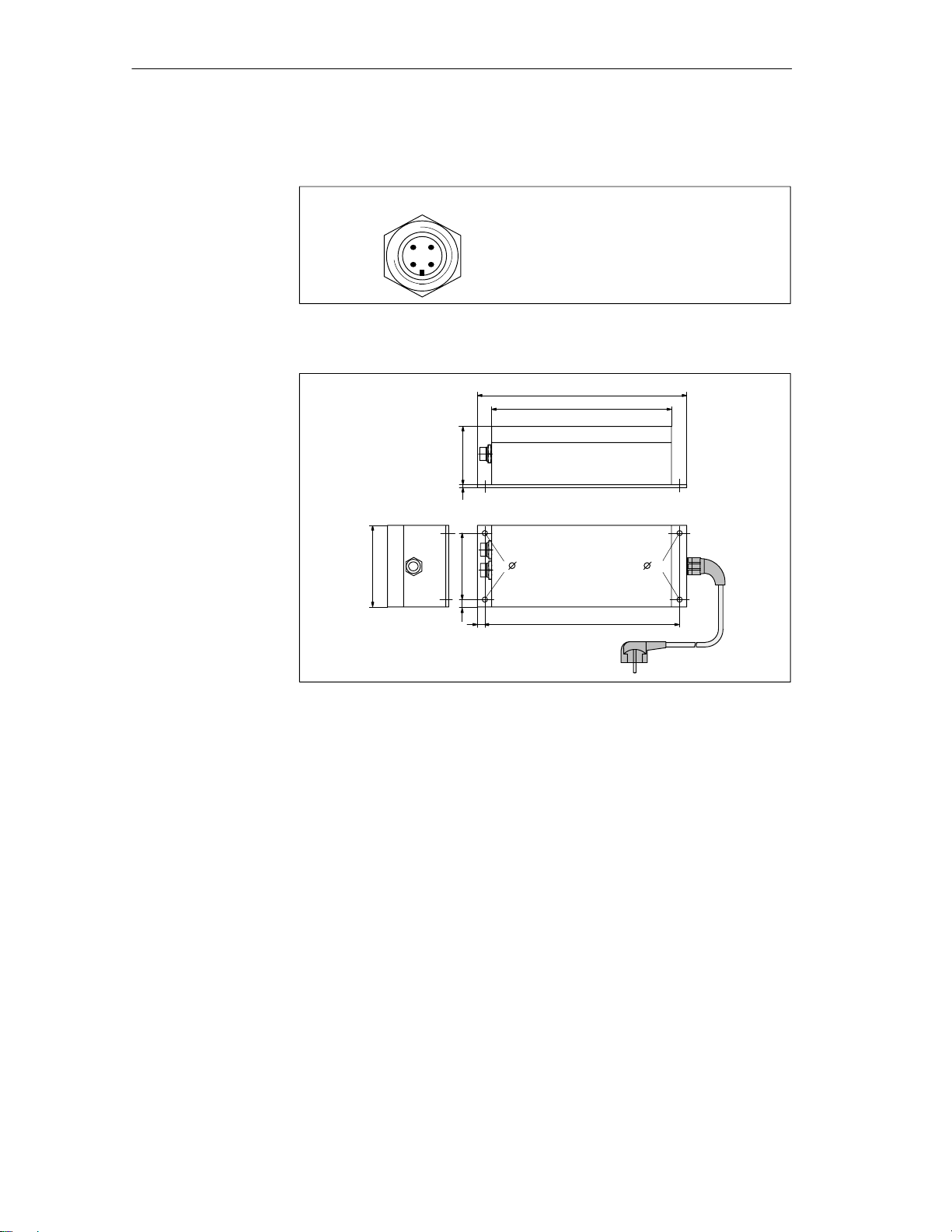
Accessories
Plug allocation of
24 V output
Outputs 1 and 2:
3
2
4
1
Figure 7-3 Plug allocation of 24 V output
Socket 1: Ground (0 V)
Socket 2: +24 V DC
Socket 3: +24 V DC
Socket 4: Ground (0 V)
Dimensions (in
mm)
205
176
573
80
7.5 65
7.5
5 5
190
Figure 7-4 Dimensions of MOBY wide–range power pack
7-6
MOBY U – Manual for Configuration, Installation and Service
(4) J31069-D0139-U001-A2-7618
 Loading...