

Page 1

Table of Contents
MOBY I
ASM 421 Interface Module
Technical Description
Brief description of the
MOBY file handler
ASM 421 hardware
Programming the
ASM 421 module
Cold start and restart
Checking entry and exit of MDS
in SLG transmission window
System and transmission times
Troubleshooting and
error messages
Warnings
1
2
3
4
5
6
7
8
6GT2 097-3AH00-0DA2
Published in March 2002
Page 2
Safety Guidelines
This manual contains notices which you should observe to ensure your own personal safety, as well to protect the
product and connected equipment. These notices are highlighted in the manual by a warning triangle and are marked as follows to the level of danger.
Danger
!
indicates that death, severe personal injury or substantial property damage will result if proper precautions are not taken.
Warning
!
indicates that death, severe personal injury or substantial property damage can result if proper precautions are not taken.
Caution
!
indicates that minor personal injury or property damage can result if proper precautions are not
taken.
Note
draws your attention to particularly important information on the product, handling the product, or to
a particular part of the documentation.
Qualified Personnel
Only qualified personnel should be allowed to install and work on this equipment. Qualified persons are defined
as persons who are authorized to commission, to ground, and to tag circuits, equipment, and systems in accordance with established safety practices and standards.
Correct Usage
Note the following:
Warning
!
This device and its components may only be used for the applications described in the catalog or
technical description, and only in connection with devices or components from other manufactorers
which have been approved or recommended by Siemens.
This product can only function correctly and savely if it is transported, stored, set up, and installed
correctly, and operated and maintained as recommended.
Trademarks
SIMATIC and MOBY are registered trademarks of SIEMENS AG.
Copyright
The reproduction, transmission or use of this document or its contents is not
permitted without express written authority. Offenders will be liable for
damages. All rights, including rights created by patent grant or registration of
a utility model or design, are reserved.
Siemens AG
Automation & Drives (A&D)
Systems Engineering (A&D SE)
P.O. Box 23 55, D-90713 Fuerth
Siemens Aktiengesellschaft Order No. 6GT2 097-3AH00-0DA2
Siemens AG 1995,2002 All rights reserved
Disclaimer of Liability
We have checked the contents of this manual for agreement with the hardware and software described. Since deviations cannot be precluded entirely,
we cannot guarantee full agreement. However, the data in this manual are
reviewed regularly and any necessary corrections included in subsequent
editions. Suggestions for improvement are welcomed.
Siemens AG 2002
Technical data subject to change.
Page 3

ASM 421 Technical Description 6GT2 097-3AH00-0DA2
Contents
1 Brief description of the MOBY file handler 2. . . . . . . . . . . . . . . . . . . . . . . . . . . . . . . . . .
2 ASM 421 hardware 5. . . . . . . . . . . . . . . . . . . . . . . . . . . . . . . . . . . . . . . . . . . . . . . . . . . . . . . .
2.1 Technical data 6. . . . . . . . . . . . . . . . . . . . . . . . . . . . . . . . . . . . . . . . . . . . . . . . . . . . . . . . . . . . .
2.2 Pin assignments 7. . . . . . . . . . . . . . . . . . . . . . . . . . . . . . . . . . . . . . . . . . . . . . . . . . . . . . . . . . .
2.2.1 Pin-outs of X1 backplane connector 7. . . . . . . . . . . . . . . . . . . . . . . . . . . . . . . . . . . . . . . . . .
2.2.2 ASM 421 connector system 8. . . . . . . . . . . . . . . . . . . . . . . . . . . . . . . . . . . . . . . . . . . . . . . . .
2.3 Setting the mode of operation 9. . . . . . . . . . . . . . . . . . . . . . . . . . . . . . . . . . . . . . . . . . . . . . .
2.4 Hardware planning 10. . . . . . . . . . . . . . . . . . . . . . . . . . . . . . . . . . . . . . . . . . . . . . . . . . . . . . . . .
2.4.1 System configuration 10. . . . . . . . . . . . . . . . . . . . . . . . . . . . . . . . . . . . . . . . . . . . . . . . . . . . . . .
2.4.2 Power supply 12. . . . . . . . . . . . . . . . . . . . . . . . . . . . . . . . . . . . . . . . . . . . . . . . . . . . . . . . . . . . . .
2.4.3 TTY cabling 13. . . . . . . . . . . . . . . . . . . . . . . . . . . . . . . . . . . . . . . . . . . . . . . . . . . . . . . . . . . . . . .
2.4.4 RS422 cabling 15. . . . . . . . . . . . . . . . . . . . . . . . . . . . . . . . . . . . . . . . . . . . . . . . . . . . . . . . . . . . .
2.4.5 V.24 cabling 16. . . . . . . . . . . . . . . . . . . . . . . . . . . . . . . . . . . . . . . . . . . . . . . . . . . . . . . . . . . . . . .
2.4.6 STG cabling 16. . . . . . . . . . . . . . . . . . . . . . . . . . . . . . . . . . . . . . . . . . . . . . . . . . . . . . . . . . . . . . .
2.4.7 DI/DO cabling 17. . . . . . . . . . . . . . . . . . . . . . . . . . . . . . . . . . . . . . . . . . . . . . . . . . . . . . . . . . . . .
3 Programming the ASM 421 module 18. . . . . . . . . . . . . . . . . . . . . . . . . . . . . . . . . . . . . . . .
3.1 3964R procedure 18. . . . . . . . . . . . . . . . . . . . . . . . . . . . . . . . . . . . . . . . . . . . . . . . . . . . . . . . . .
3.2 Telegram format 20. . . . . . . . . . . . . . . . . . . . . . . . . . . . . . . . . . . . . . . . . . . . . . . . . . . . . . . . . . .
3.3 Blocking of long data sequences 21. . . . . . . . . . . . . . . . . . . . . . . . . . . . . . . . . . . . . . . . . . . . .
3.4 File handler commands 22. . . . . . . . . . . . . . . . . . . . . . . . . . . . . . . . . . . . . . . . . . . . . . . . . . . . .
3.4.1 FORMAT 23. . . . . . . . . . . . . . . . . . . . . . . . . . . . . . . . . . . . . . . . . . . . . . . . . . . . . . . . . . . . . . . . .
3.4.2 CREATE 24. . . . . . . . . . . . . . . . . . . . . . . . . . . . . . . . . . . . . . . . . . . . . . . . . . . . . . . . . . . . . . . . . .
3.4.3 QUEUE-WRITE 25. . . . . . . . . . . . . . . . . . . . . . . . . . . . . . . . . . . . . . . . . . . . . . . . . . . . . . . . . . .
3.4.4 WRITE/UPDATE 27. . . . . . . . . . . . . . . . . . . . . . . . . . . . . . . . . . . . . . . . . . . . . . . . . . . . . . . . . . .
3.4.5 READ 29. . . . . . . . . . . . . . . . . . . . . . . . . . . . . . . . . . . . . . . . . . . . . . . . . . . . . . . . . . . . . . . . . . . .
3.4.6 QUEUE-READ 31. . . . . . . . . . . . . . . . . . . . . . . . . . . . . . . . . . . . . . . . . . . . . . . . . . . . . . . . . . . .
3.4.7 DELETE 34. . . . . . . . . . . . . . . . . . . . . . . . . . . . . . . . . . . . . . . . . . . . . . . . . . . . . . . . . . . . . . . . . .
3.4.8 COVER 35. . . . . . . . . . . . . . . . . . . . . . . . . . . . . . . . . . . . . . . . . . . . . . . . . . . . . . . . . . . . . . . . . .
3.4.9 DIR 36. . . . . . . . . . . . . . . . . . . . . . . . . . . . . . . . . . . . . . . . . . . . . . . . . . . . . . . . . . . . . . . . . . . . . .
3.4.10 MDS status 37. . . . . . . . . . . . . . . . . . . . . . . . . . . . . . . . . . . . . . . . . . . . . . . . . . . . . . . . . . . . . . .
3.4.11 ASM Status 38. . . . . . . . . . . . . . . . . . . . . . . . . . . . . . . . . . . . . . . . . . . . . . . . . . . . . . . . . . . . . . .
3.4.12 TRACE 39. . . . . . . . . . . . . . . . . . . . . . . . . . . . . . . . . . . . . . . . . . . . . . . . . . . . . . . . . . . . . . . . . . .
3.4.13 ATTRIB 40. . . . . . . . . . . . . . . . . . . . . . . . . . . . . . . . . . . . . . . . . . . . . . . . . . . . . . . . . . . . . . . . . . .
3.4.14 NEXT 41. . . . . . . . . . . . . . . . . . . . . . . . . . . . . . . . . . . . . . . . . . . . . . . . . . . . . . . . . . . . . . . . . . . .
3.4.15 RESET 42. . . . . . . . . . . . . . . . . . . . . . . . . . . . . . . . . . . . . . . . . . . . . . . . . . . . . . . . . . . . . . . . . . .
3.4.16 LOAD/MOVE 44. . . . . . . . . . . . . . . . . . . . . . . . . . . . . . . . . . . . . . . . . . . . . . . . . . . . . . . . . . . . . .
3.5 Telegrams from file handler 46. . . . . . . . . . . . . . . . . . . . . . . . . . . . . . . . . . . . . . . . . . . . . . . . . .
3.5.1 Start-up message 46. . . . . . . . . . . . . . . . . . . . . . . . . . . . . . . . . . . . . . . . . . . . . . . . . . . . . . . . . .
3.5.2 Change in proximity status 46. . . . . . . . . . . . . . . . . . . . . . . . . . . . . . . . . . . . . . . . . . . . . . . . . .
4 Cold start and restart 47. . . . . . . . . . . . . . . . . . . . . . . . . . . . . . . . . . . . . . . . . . . . . . . . . . . . .
5 Checking entry and exit of MDS in SLG transmission window 49. . . . . . . . . . . . . . .
5.1 MDS recognition by field scanning 50. . . . . . . . . . . . . . . . . . . . . . . . . . . . . . . . . . . . . . . . . . . .
5.2 Without entry/exit monitoring 51. . . . . . . . . . . . . . . . . . . . . . . . . . . . . . . . . . . . . . . . . . . . . . . .
5.3 MDS control using field scanning and 1 DI 52. . . . . . . . . . . . . . . . . . . . . . . . . . . . . . . . . . . . .
5.4 MDS control using 2 DIs 53. . . . . . . . . . . . . . . . . . . . . . . . . . . . . . . . . . . . . . . . . . . . . . . . . . . .
5.5 Without entry/exit monitoring 54. . . . . . . . . . . . . . . . . . . . . . . . . . . . . . . . . . . . . . . . . . . . . . . .
5.6 Special Operating Mode (Test Operation) 55. . . . . . . . . . . . . . . . . . . . . . . . . . . . . . . . . . . . .
5.7 Diagram showing possible MDS states at an SLG 56. . . . . . . . . . . . . . . . . . . . . . . . . . . . . .
6 System and transmission times 59. . . . . . . . . . . . . . . . . . . . . . . . . . . . . . . . . . . . . . . . . . . .
7 Troubleshooting and error messages 61. . . . . . . . . . . . . . . . . . . . . . . . . . . . . . . . . . . . . .
8 Warnings 67. . . . . . . . . . . . . . . . . . . . . . . . . . . . . . . . . . . . . . . . . . . . . . . . . . . . . . . . . . . . . . . . .
6GT2 002-0DA00 ASM 421 / V .24
6GT2 002-0DB00 ASM 421 / RS422
6GT2 002-0DC00 ASM 421 / TTY
– 1 –
Subject to change without notice!
J31069-D0142-U001-A0-7618
RD: 03/02
Page 4
ASM 421 Technical Description6GT2 097-3AH00-0DA2
1 Brief description of the MOBY file handler
The ASM 421 is a serial interface module for the MOBY I identification system. It can be driven from any
computer, PC or PLC using the 3964R procedure. The MOBY I file handler is implemented on the
ASM 421.
What is the file handler?
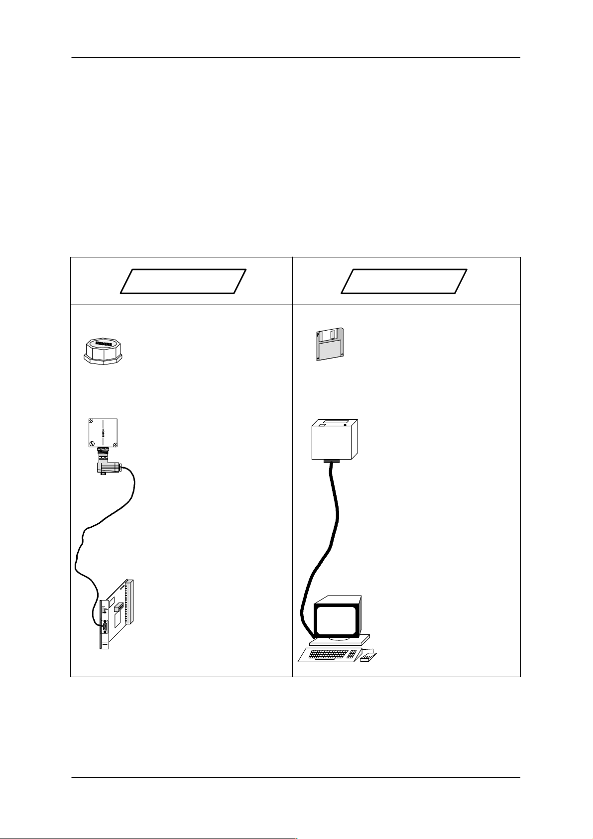
The file handler is a data management system for the MOBY I identification system. It consists of a program that runs on the interface module. The MDS (mobile data carrier) and SLG (read-write unit) components of MOBY I are identical with and without file handler.
For better understanding of the MOBY file handler, it works in much the same way as a floppy disk system.
MOBY I File Handler Floppy Disk System
MDS:
Data is stored electronically in
the MDS on a memory chip
(RAM or EEPROM).
SLG:
The SLG modulates the data
stream arriving from the ASM
and demodulates the data
stream arriving from the MDS.
The positioning of the MDS
must lie within the transmission window of the SLG. This
amounts to several centimeters.
The MOBY I interface module
(ASM 421) provides the user
interface. A USART module on
the ASM produces the serial
data stream for the SLG.
Floppy Disk:
Data is written magnetically on
a floppy disk.
Floppy Drive:
The floppy drive converts the
data impulses arriving from the
PC into a write string for the
read/write head (or vice versa)
The floppy disk must be positioned very exactly over the
read/write head as this generates only very small magnetic
fields.
A PC controls the floppy drive
and exchanges data with it via
a parallel interface. The coding
and decoding of the data takes
place in a floppy controller in
the PC.
Subject to change without notice!
RD: 03/02
J31069-D0142-U001-A0-7618
– 2 –
6GT2 002-0DA00 ASM 421 / V .24
6GT2 002-0DB00 ASM 421 / RS422
6GT2 002-0DC00 ASM 421 / TTY
Page 5
ASM 421 Technical Description 6GT2 097-3AH00-0DA2
Similarities between MOBY file handler and a floppy disk
– The user does not access physical memory addresses
– The user addresses the data via logical names, which consist of up to eight letters
– The conversion of the logical names into physical memory addresses is carried out by software
in the interface module:
File handler ↔ Disk-Operating-System (DOS)
– Contiguous data blocks are called files
– The management of files of differing lengths is carried out by a software procedure (file handler)
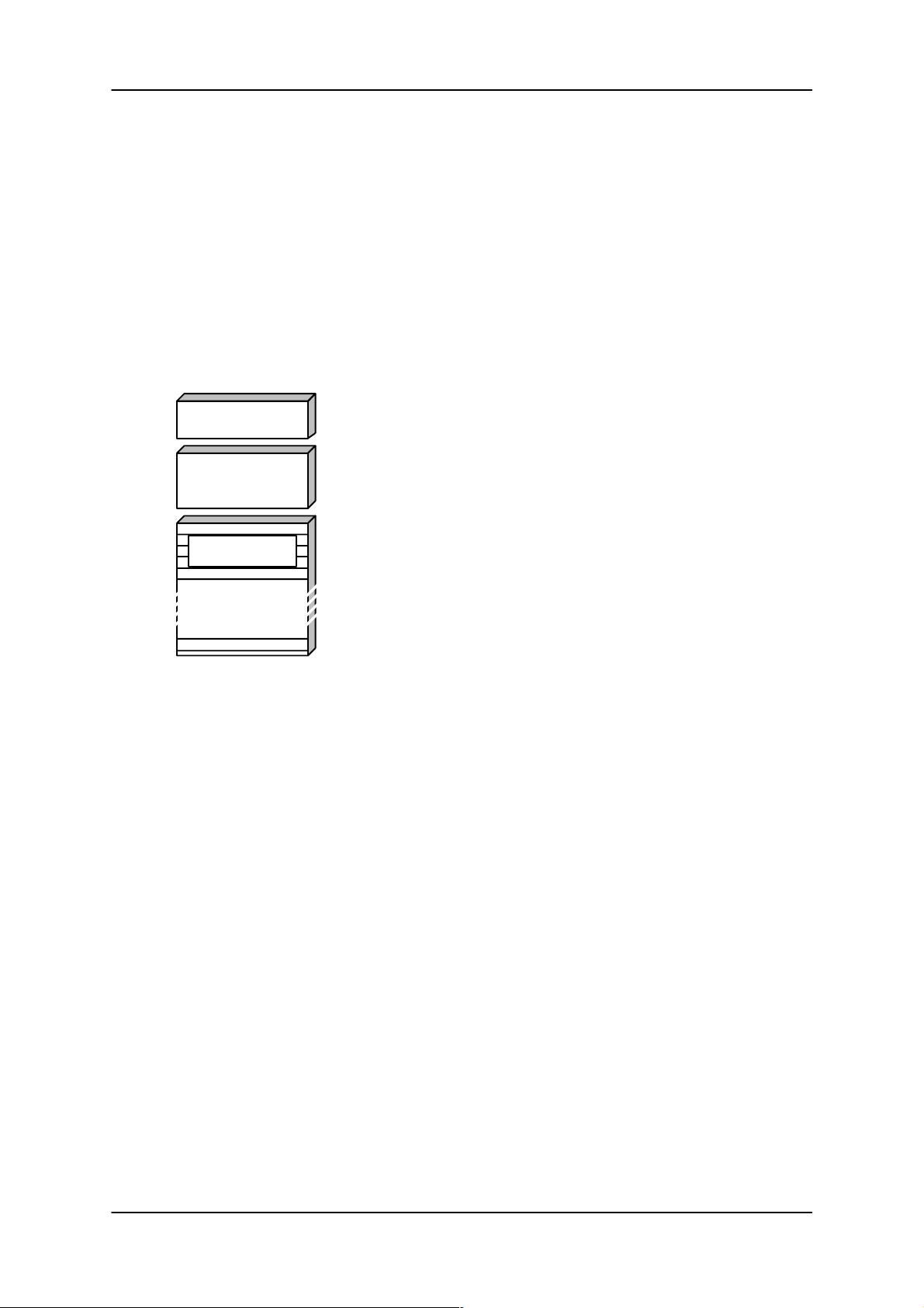
– The memory is divided into 3 areas:
The system area contains general system data:
System area
Directory
– Volume name
– Format and size of memory
– Data coding
All file names and file lengths are stored in the directory. The file handler calculates
the physical addresses of the user data from these entries.
User data
The largest memory area is reserved for user data, which can be stored in any
form (ASCII, binary, hexadecimal, decimal, etc.). The user data is managed by the
file handler in blocks. On a floppy, these blocks are known as “sectors” or “logical
blocks”.
Advantages of the file handler for the MOBY I user.
– When specifying a system, it is only necessary to define the names (file names) of the individual
data objects that are to be stored on the MDS.
– The project engineer does not need to structure MDS memory at all.
– The list of data objects can be changed or extended as required during detailed planning. The
MDS data structure does not need to be taken into account.
– The lengths of the individual data objects do not need to be known.
– The description of each data object is a name of up to eight letters. The choice of name can be
directly related to the object (e.g., WORKSNO; SERIALNO; QUALITY; ADDRESS; ORDER;
Drillprog; Turnprog; Millprog;...)
– The programmer does not need to work with absolute addresses. Several sources of program-
ming errors are thus excluded (e.g. double addressing, input errors leading to wrong addresses
and file lengths). The file handler converts the file names into physical MDS addresses.
– Details of the files stored on the MDS can be requested by the “directory” command.
– Data objects can be accessed simply and rapidly using the STG 4F service and test unit. This i s
of great advantage to commissioning and maintenance personnel.
– The documentation of the MDS memory structure is very simple and easy to understand, con-
sisting only of a list of file names.
– The user can allocate access rights. Unauthorized deletion and overwriting of user data is thus
avoided.
6GT2 002-0DA00 ASM 421 / V .24
6GT2 002-0DB00 ASM 421 / RS422
6GT2 002-0DC00 ASM 421 / TTY
– 3 –
Subject to change without notice!
J31069-D0142-U001-A0-7618
RD: 03/02
Page 6

ASM 421 Technical Description6GT2 097-3AH00-0DA2
Formats of different MDS memories:
MDS units with various memory sizes are available with MOBY I. Each type of MDS must be formatted
before processing with the file handler. During formatting, the MDS is given a data structure, divided into
system area, directory and user data. The MDS type is passed to the file handler by the FORMAT command (see section 3.4.1).
The following table shows how the file handler structures the various types of MDS:
Type
(Hex)
Enter this
parameter
when initializing
MDS capacity
in bytes (gross)
Total MDS
memory size
01H
81H
02H
03H
83H
04H
84H
05H
85H
06H
86H
2.045
1.778**
8,189
7,154
32,765
28,658**
* With ECC operation
62
42 *
62
128
112
Max. no. of
files
Max.number of
files that can
be stored
1
1
2
3
3
16
16
32
*
32
64
64
User data in
bytes (net)
Max. no. of user
bytes that can be
written to the MDS
27
7
12
60
45
1.680
1.440
7,456
6,464
31,488
27,520
Number of
blocks
The product of no. of blocks
and block size gives the user
data length (net) in bytes
1
1
2
6
5
105
90
233
202
246
215
Block size
in bytes
27
7
6
10
9
16
16
32
32
128
128
Subject to change without notice!
RD: 03/02
J31069-D0142-U001-A0-7618
– 4 –
6GT2 002-0DA00 ASM 421 / V .24
6GT2 002-0DB00 ASM 421 / RS422
6GT2 002-0DC00 ASM 421 / TTY
Page 7
ASM 421 Technical Description 6GT2 097-3AH00-0DA2
2 ASM 421 hardware
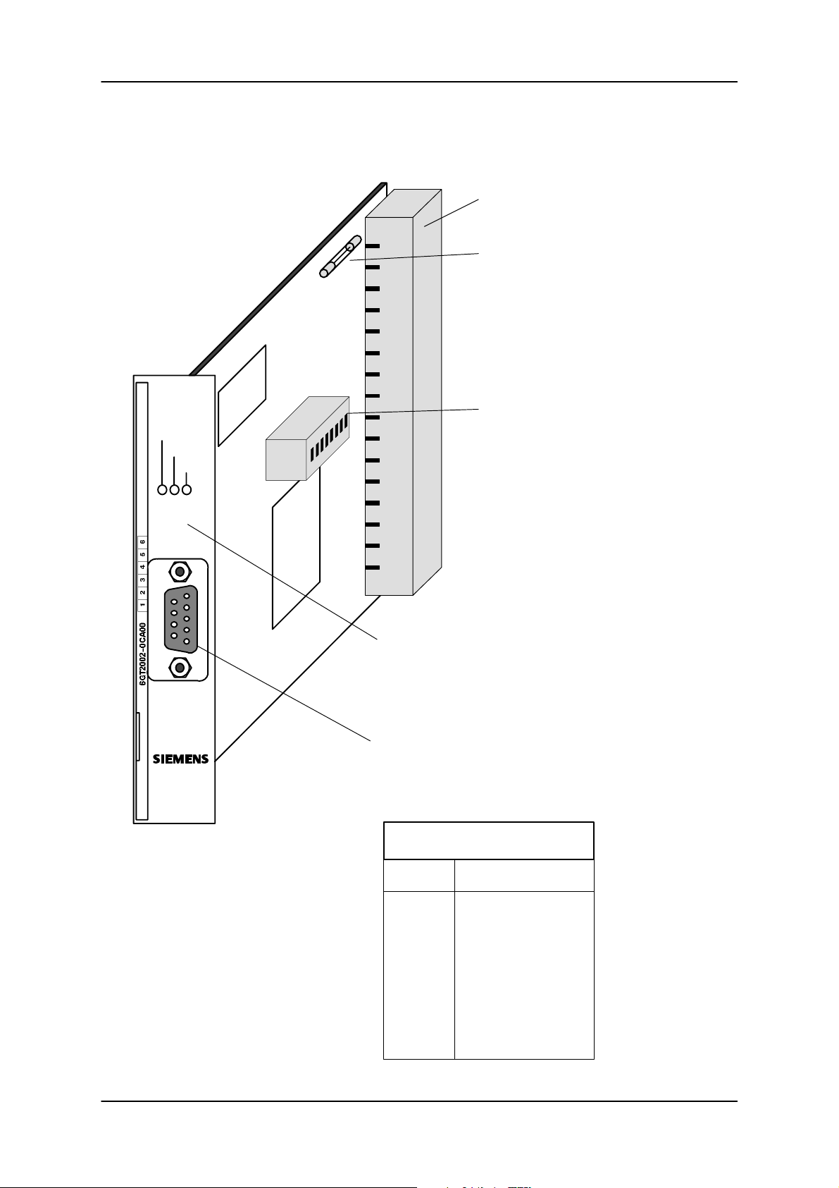
Backplane connector (X1)
Fuse
(T 315 mA)
ANW
Active
Error
MOBY
EPROM
Switch bank (S1)
for setting mode of operation
CPU
3 LEDs:
red LED: indicates a fault (see table in chap. 7)
yellow LED: indicates that the SLG device is active
green LED: indicates that an MDS is present
9–way subminiature D connector (screw locking)
(X2) for connecting the SLG read/write device
(The SLG can also be connected via the back–
plane connector if required).
6GT2 002-0DA00 ASM 421 / V .24
6GT2 002-0DB00 ASM 421 / RS422
6GT2 002-0DC00 ASM 421 / TTY
Pin assignments to SLG
Pin Function
1
2
3
4
5
6
7
8
9
reserve
+ transmit
+ receive
reserve
– receive
– transmit
ground () V)
+ 24 V
reserve
housing cable screen
housing = connector housing
– 5 –
Subject to change without notice!
RD: 03/02
J31069-D0142-U001-A0-7618
Page 8

2.1 Technical data
Environmental conditions:
– operating temperature: 0 °C to + 55 °C
– storage temperature: – 40 °C to + 70 °C
Degree of protection to IEC 529: IP 00
Serial interface (to computer/PC):
– transmission rate: 2400 to 19200 Baud
– procedure: 3964R; odd/even parity
– cable lengths: TTY 1000 m (shielded)
RS422 1000 m (shielded)
V.24 30 m (shielded)
Serial interface (to SLG):
– transmission rate (gross): 19200 Baud
– procedure: Asynchronous: 8 bit data: even parity
MOBY I: MDS protocol
– cable lengths: SLG dependent; max. 1000 m
(see cable configurations in manual
for configuration, installation and service)
ASM 421 Technical Description6GT2 097-3AH00-0DA2
Power supply: 20 to 30 V DC
Current input:
– max. off-load current: 200 mA
(no SLG; DO’s off-load)
Dimensions:
– L x W x H 160 x 100 x 20 (mm)
DI/DO; Select; Request; Error; ANW:
– digital inputs 3
non-floating
logical “0”: 0 V to 8 V
logical “1”: 15 V to 24 V
(Ri = 10 kOhm)
delay: < 10 ms
– digital outputs 5
non-floating
(internal power supply)
short-circuit proof
I
= 200 mA (per DO; or for 2 DO’s)
max
Subject to change without notice!
RD: 03/02
J31069-D0142-U001-A0-7618
– 6 –
6GT2 002-0DA00 ASM 421 / V .24
6GT2 002-0DB00 ASM 421 / RS422
6GT2 002-0DC00 ASM 421 / TTY
Page 9
ASM 421 Technical Description 6GT2 097-3AH00-0DA2
2.2 Pin assignments
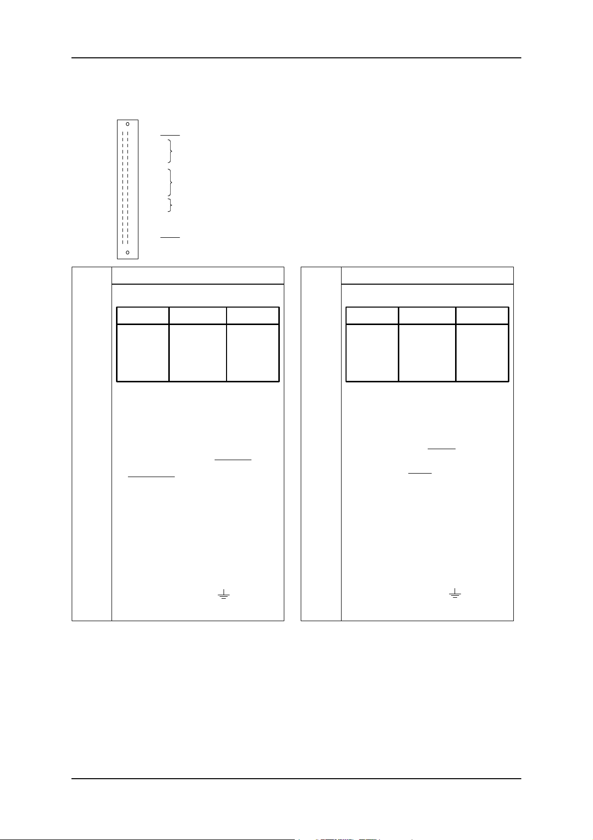
2.2.1 Pin-outs of X1 backplane connector
b2
b4
b6
b8
b10
b12
b14
b2
b4
b6
b8
b10
b12
b14
b16
b18
b20
b22
b24
b26
b28
b30
b32
Z2
Z4
Z6
Z8
Z10
Z12
Z14
Z16
Z18
Z20
Z22
Z24
Z26
Z28
Z30
X32
Power supply
Serial interface to user
Optional control and signal line
Optional SLG connection
Protective ground (shield)
0 V
Interface (type dependent)
V.24 RS422 TTY
––
RxD
––
DI0
MDS entry when EAKO=2
R+
D+
D–
and EAKO=3***
DO0
free
+EM
+SE
––*
z2
z4
z6
z8
z10
z12
z14
24 V
Interface (type dependent)
V.24 RS422 TTY
TxD
–
GND
DI1
MDS exit when EAKO=3***
DO1
free
E+
R–
E–
–EM
–SE
––
b16
ASM has user data or
z16
Select module (Select)
acknowledgement (Request)
b18
Error code (same as
z18
red LED)
b20**
b22**
b24
b26
b28
b30
b32
R+ (terminating resistor) TxD (transmit data)
E+ (receive) RxD (receive data)
D+ (transmit) +EM (receive)
R– (terminating resistor) –EM (receive)
D– (transmit) +SE (transmit)
E– (receive) –SE (transmit)
* Pin b8 must not be connected in TTY mode!
** These data connections to the SLG are available as options on the backplane connector. They are identical to the
*** EAKO = entry/exit checking (see chapter 5)
**** The presence of an MDS is indicated with 0 V level on this pin.
SLG receive +
SLG transmit +
Protective ground
()
0 V
corresponding connections on the 9-pole submin. D connector.
z20**
z22**
z24
z26
z28
z30
z32
Presence (ANW) ****
(same as green LED)
SLG receive –
SLG transmit –
Protective ground
()
6GT2 002-0DA00 ASM 421 / V .24
6GT2 002-0DB00 ASM 421 / RS422
6GT2 002-0DC00 ASM 421 / TTY
– 7 –
Subject to change without notice!
RD: 03/02
J31069-D0142-U001-A0-7618
Page 10
ASM 421 Technical Description6GT2 097-3AH00-0DA2
2.2.2 ASM 421 connector system
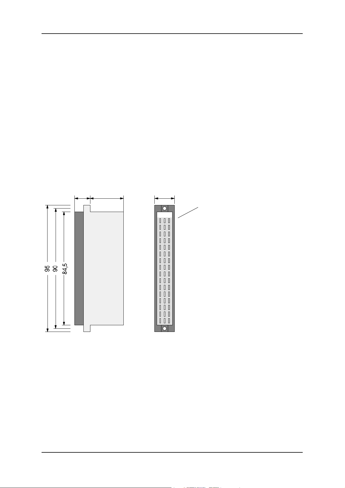
Connector: The connector used with the ASM 520 is a 48-way male connector conforming to DIN 41612
design F, whose soldering pins are bent through 90°. Rows z and b only are connected and
soldered directly to the ASM 520.
Socket: Female connectors conforming to DIN 41612 design F must be used as mating components
for the ASM 421 connector. In principle, all 48-way “female connectors conforming to
DIN 41612 design F” are suitable.
Various types of female connectors are available, e.g.:
– with solder terminations
– with a screw connection
– as a wire wrap version
e.g. SFL 0,5 / F 32 / 2 B:
10.5 23.6 14.8
zbd
Features:
– 3 rows of connectors
– Number of contacts: 32 (2 rows, each with 16 contacts)
Female connector with screw connection 0.5 mm2; rows z and b connected
– Contact principle: insulation displacement connector with double-sided contact spring
– Catch hooks and elements to ensure secure contact between male and female connectors
Subject to change without notice!
RD: 03/02
J31069-D0142-U001-A0-7618
– 8 –
6GT2 002-0DA00 ASM 421 / V .24
6GT2 002-0DB00 ASM 421 / RS422
6GT2 002-0DC00 ASM 421 / TTY
Page 11
ASM 421 Technical Description 6GT2 097-3AH00-0DA2
2.3 Setting the mode of operation
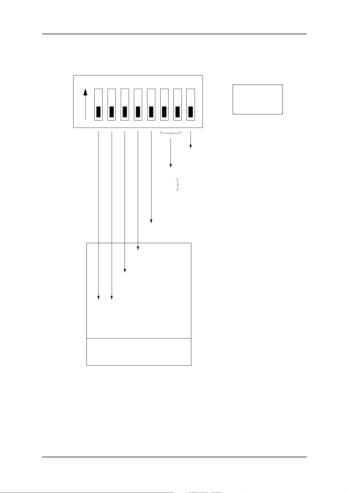
Switch bank S1:
4532ON 1 7 86
ON
“1”
1 = Proximity message from ASM;
0 = no proximity message
Access rights of this ASM station
00
Step “D” (= Delete); all commands allowed
01
10 Step “W” (= Write); Formatting of MDS and
deletion of files are not allowed
11 Step “R” (= Read only); only read operations on
the MDS are allowed
0 = Siemens file handler is set up
1 = reserved for 8-E41
1 = Master
0 = Slave
OFF=^=^
(Z-message)
“0”
1 = odd parity
0 = even parity
Baud rate:
00 = 9600 Baud
01 = 4800 Baud
10 = Reserved for 38.4 KBaud
11 = 19200 Baud
Setting of the
3964R procedure
to the user
6GT2 002-0DA00 ASM 421 / V .24
6GT2 002-0DB00 ASM 421 / RS422
6GT2 002-0DC00 ASM 421 / TTY
– 9 –
Subject to change without notice!
RD: 03/02
J31069-D0142-U001-A0-7618
Page 12
2.4 Hardware planning
2.4.1 System configuration
ASM 421 Technical Description6GT2 097-3AH00-0DA2
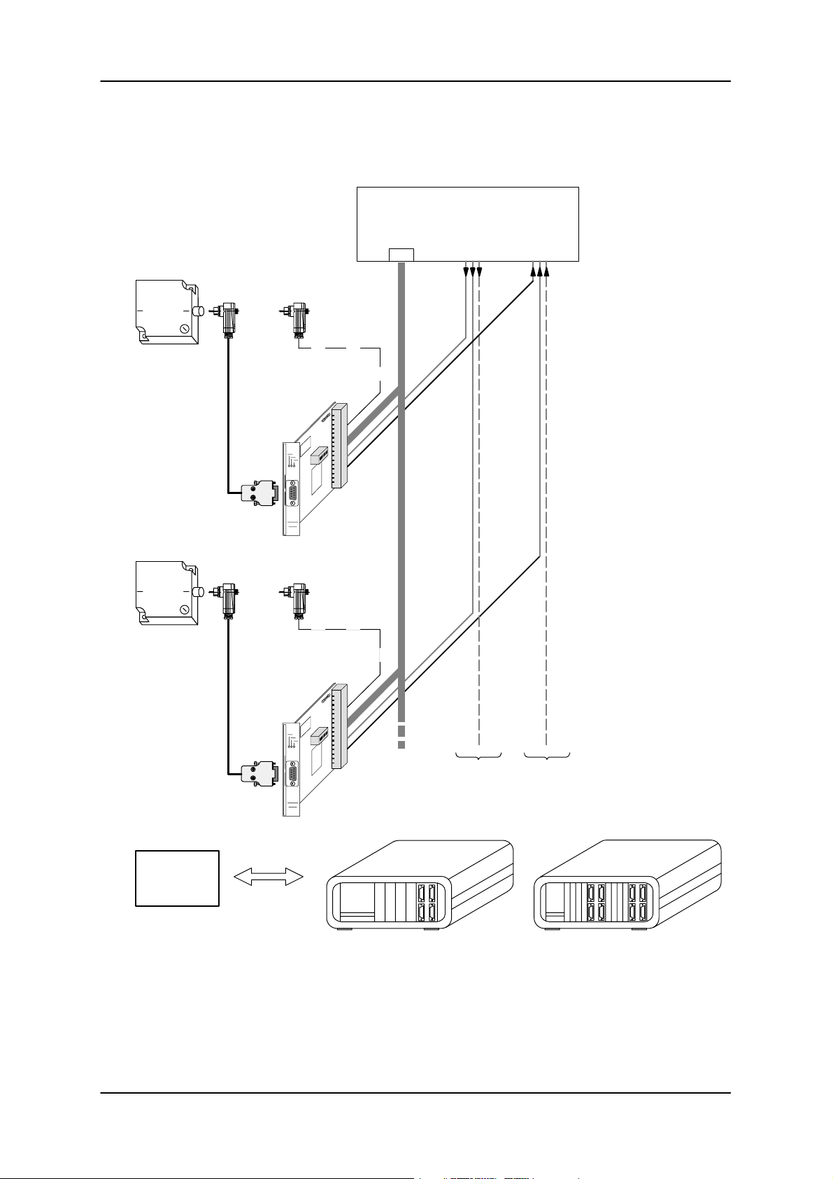
The SLG read/write device can be connected to
either the X1 backplane connector or the 9-way
subminiature D connector X2.
SIEMENS
SLG
read/write
device
SIEMENS
Serial
interface*
Computer/PC
RequestSelect
DIDO
Please note:
The Select and Request lines may be
omitted if only one
ASM 421 is being
driven fro m a s e r i a l interface. The external
wiring of unnecessary
signals can also be
omitted.
* Daisy-chain configurations are only
possible with the
RS422 and TTY interfaces.
SLG
read/write
device
PLC, PC
serial
or
computer
interface
Two standard configurations
are available
– rack with 4 slots
– rack with 8 slots.
one select line
for each
ASM 421
one request line
for each
ASM 421
Subject to change without notice!
RD: 03/02
J31069-D0142-U001-A0-7618
– 10 –
6GT2 002-0DA00 ASM 421 / V .24
6GT2 002-0DB00 ASM 421 / RS422
6GT2 002-0DC00 ASM 421 / TTY
Page 13
ASM 421 Technical Description 6GT2 097-3AH00-0DA2
ASM 421 interface modules can only be daisy-chained if they are using an RS422 or TTY interface. This
allows up to 16 interface modules to be driven from one serial interface.
The computer/PC must have a digital input (DI) and a digital output (DO) for each ASM 421.
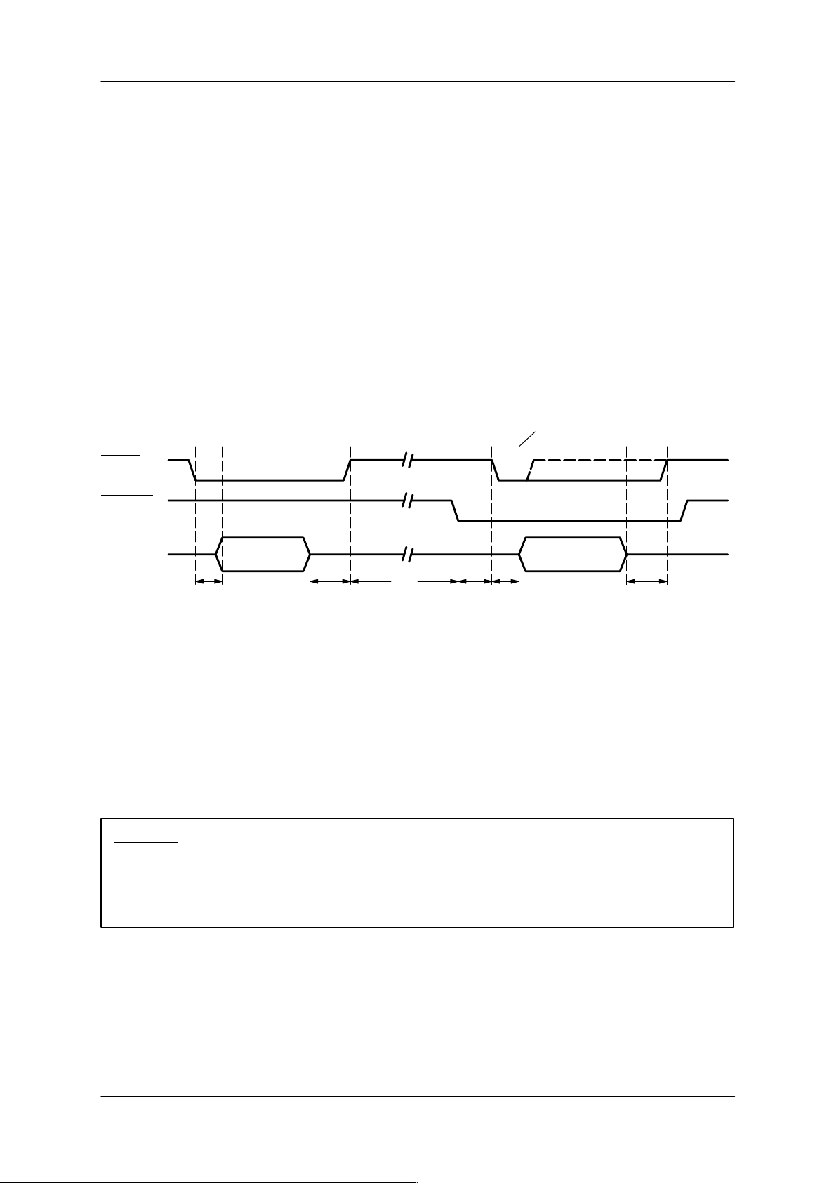
Mode of operation:
Programming the ASM:
The computer/PC “selects” the module and then sends it the task telegram.
Command processing:
The ASM then processes the command. How long this takes depends on the command and can
last any amount of time (when there is no MDS in the field).
Send result to user:
By setting the “Request” flag, the ASM indicates that it wants to send a telegram. The computer/PC
recognizes this and “selects” the module. The selected ASM then sends the result telegram.
Select interrogate
Select
*
**
Request
Data
t
1
Task telegram
to ASM
t
t
2
3
t
t
5
4
Response
telegram from ASM
t
2
t1 100 ms : Wait time from select until data transmission.
t2 0 : Wait time from data transmission until deselection of ASM 421
t3Depends on : Processing of user command by the ASM 421
command
t4 0 : Time from “request active“ until selection of ASM 421
t5= 0 ... 30 ms : Time from selection of the module until transmission of the result telegram
Important: * At the result telegram the ASM only interrogates the “select” at the beginning of a
transmission. If the “select” is deactivated during transmission of the telegram, the
ASM will nevertheless send the complete telegram to the computer.
This ensures that no garbled telegrams from the ASM are transmitted.
** The select line must be set high for the entire time that an outgoing telegram is being
sent.
6GT2 002-0DA00 ASM 421 / V .24
6GT2 002-0DB00 ASM 421 / RS422
6GT2 002-0DC00 ASM 421 / TTY
– 11 –
Subject to change without notice!
RD: 03/02
J31069-D0142-U001-A0-7618
Page 14
ASM 421 Technical Description6GT2 097-3AH00-0DA2
2.4.2 Power supply
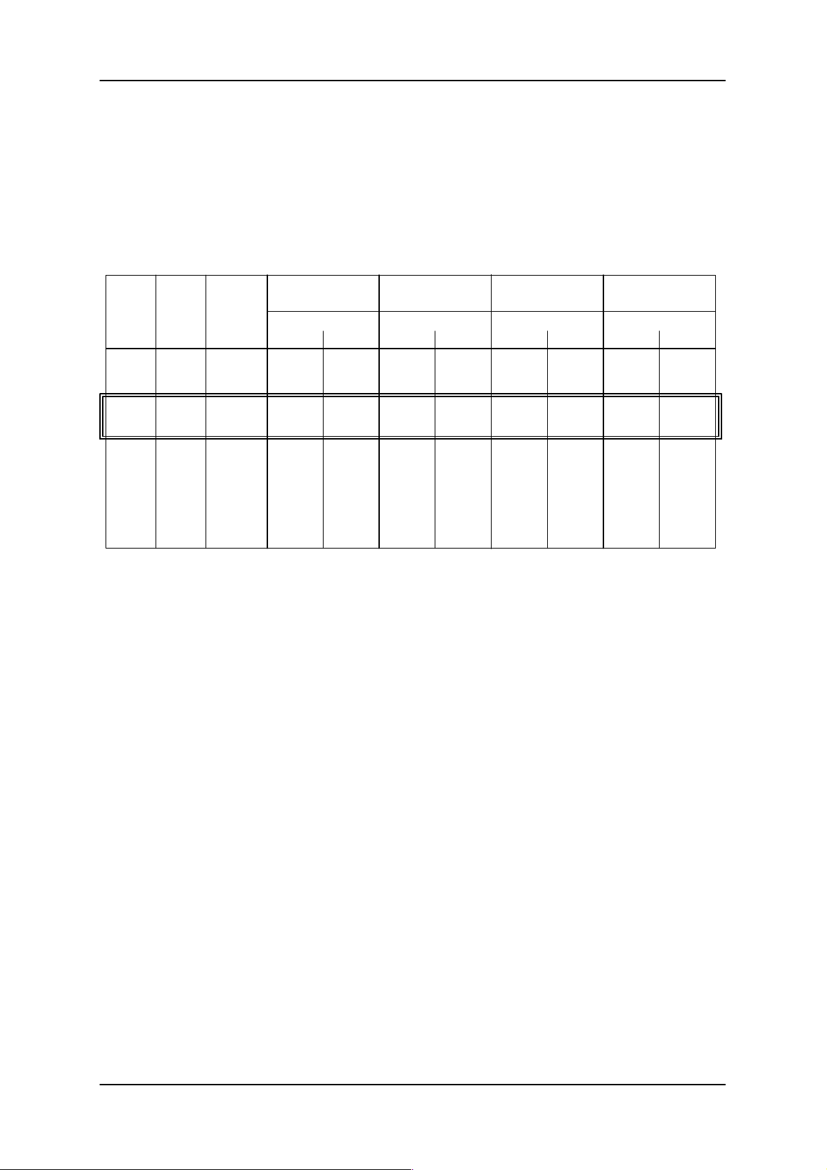
The cable between the ASM 421 and the SLG read/write device is a 6-core shielded cable, of which 4
cores are dedicated to the data interface and 2 to the power supply for the SLG read/write device. The
maximum length of the data cables can, depending on the physical interface, be anything up to 1000 m.
The maximum permitted cable run is generally shorter if the 24 V supply for the SLG read/write device is
used by the ASM 421. The maximum cable length also depends on the level of voltage drop. The following
table gives an overview of permitted cable lengths:
Conductor
crosssection
2
[mm
0.07
0.2
0.5
0.8
1.5
Conductor
dia.
[mm]
]
0.3
0.5
0.8
1.0
1.4
Resistance
/km *)
550
185
70
50
24
SLG 40 / SLG 41
(I=90 mA)
Max. cable length when
120
360
950
1000
1000
UV = 30 V
240
720
1000
1000
1000
UV = 24 V
SLG 42 (I=180 mA)
Max. cable length when Max. cable length when
UV = 24 V UV = 30 V
40 100
120 300
310 790
440 1000
920 1000
SLG 43 (I=250 mA)
UV = 24 V UV = 30 V
30 70
85 210
230 570
320 800
660 1000
SLG 44 (I=80 mA)
Max. cable length when
UV = 24 V UV = 30 V
90 200
250 650
700 1000
1000 1000
1000 1000
*) The values for resistance are average values and relate to the feed and return conductors. An individu-
al conductor has half the quoted resistance.
If cable runs longer than those specified in the table are used, the 24 V supply for the SLG read/write
device must not be used by the ASM 421. Instead, a 24 V supply must be fed directly to the SLG. (See
manual for configuration, installation and service; chapter 3.10; cable and connector allocation.)
Highlighted field:
The standard shielded LiYCY 6 x 0.25 cable recommended by SIEMENS. This cable is available from
SIEMENS under the order number 6GT2090-0A...1).
24 V supply to ASM 421:
The maximum length of the power supply cable for the ASM 421 is restricted to 20 m. If a longer cable is
used, or several ASMs are supplied from a single cable, the voltage drop on the supply cable to both
the ASM 421 and SLG read/write device must be taken into account. If necessary, the cross section o f
the supply cable should be increased.
1
) According to length code
Subject to change without notice!
RD: 03/02
J31069-D0142-U001-A0-7618
– 12 –
6GT2 002-0DA00 ASM 421 / V .24
6GT2 002-0DB00 ASM 421 / RS422
6GT2 002-0DC00 ASM 421 / TTY
Page 15
ASM 421 Technical Description 6GT2 097-3AH00-0DA2
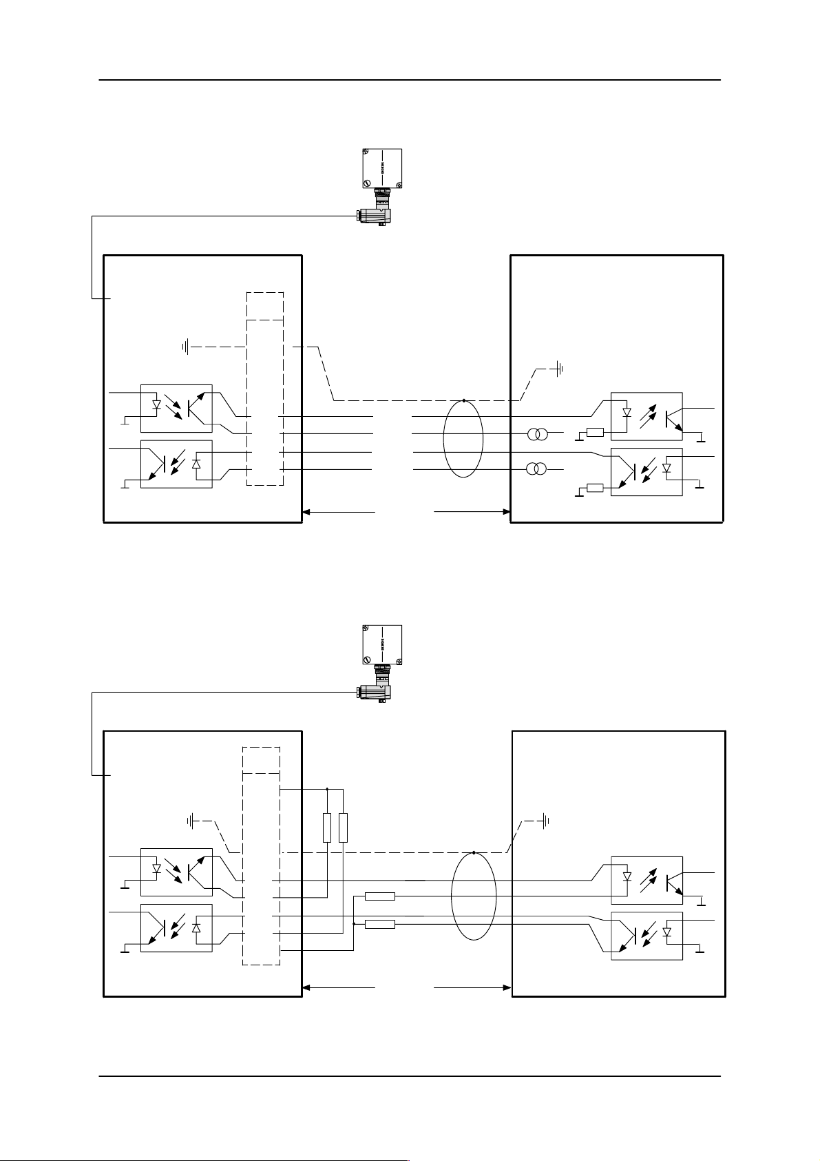
2.4.3 TTY cabling
SLG
ASM 421 (passive) Computer (active)
X2
1–9
TxD
RxD
X1
b30/
z30
z6
b6
z4
b4
–SE
+SE
–EM
+EM
RxD
+
TxD
+
max.
length
1000 m
The ASM module does not contain any power sources for energizing the active part of the TTY interface.
Should, however, it become necessary for the ASM to power the interface, the ASM should be wired as
follows to make it active:
SLG
ASM 421 (active)
X2
X1
Computer (passive)
1–9
z2
RR
b30/
TxD
z30
RxD
z6
RxD
b6
z4
b4
R
TxD
R
b32
max.
length
1000 m
The resistors R should each have a value of 470 Ohms to produce a current loop of 20 ... 30 mA
(P = 0.5 W).
6GT2 002-0DA00 ASM 421 / V .24
6GT2 002-0DB00 ASM 421 / RS422
6GT2 002-0DC00 ASM 421 / TTY
– 13 –
Subject to change without notice!
RD: 03/02
J31069-D0142-U001-A0-7618
Page 16
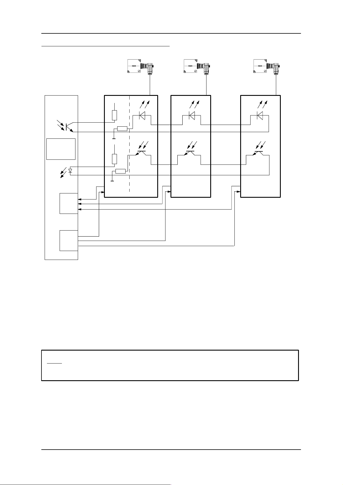
Example of a daisy-chain configuration (see 2.4.1)
ASM 421 Technical Description6GT2 097-3AH00-0DA2
CP
or
Computer
Request
dig.
inputs
Select
dig.
out–
puts
+SE
–SE
+EM
–EM
SLG
ASM 421 No. 1 ASM 421 No. 2 ASM 421 No. 4
+24 V
z4
4
7
z4
b16
z16
0
+24 V
4
7
0
470
470
b32
b32
b4
** *
b6 z6
**
SLG SLG
.......
z4 b4
.......
b6 z6
*
b16
z16
z4
b4
b6
b16
z16
active passive passive
passive
*) This line must be looped through from the computer to the last ASM!
Where possible, the computer should handle the active part of the TTY interface, in which case the resistors shown on ASM no. 1 will not be needed.
If this is not possible (as shown in the diagram), the active part of the interface must be simulated in the
connector of ASM no. 1 using 4 resistors (R = 470 Ohm).
The numbers in the diagram refer to pins in the 48-way female connector.
Note: With this cabling, all the wired ASMs must actually be connected, otherwise the circuit will
remain open!
Subject to change without notice!
RD: 03/02
J31069-D0142-U001-A0-7618
– 14 –
6GT2 002-0DA00 ASM 421 / V .24
6GT2 002-0DB00 ASM 421 / RS422
6GT2 002-0DC00 ASM 421 / TTY
Page 17
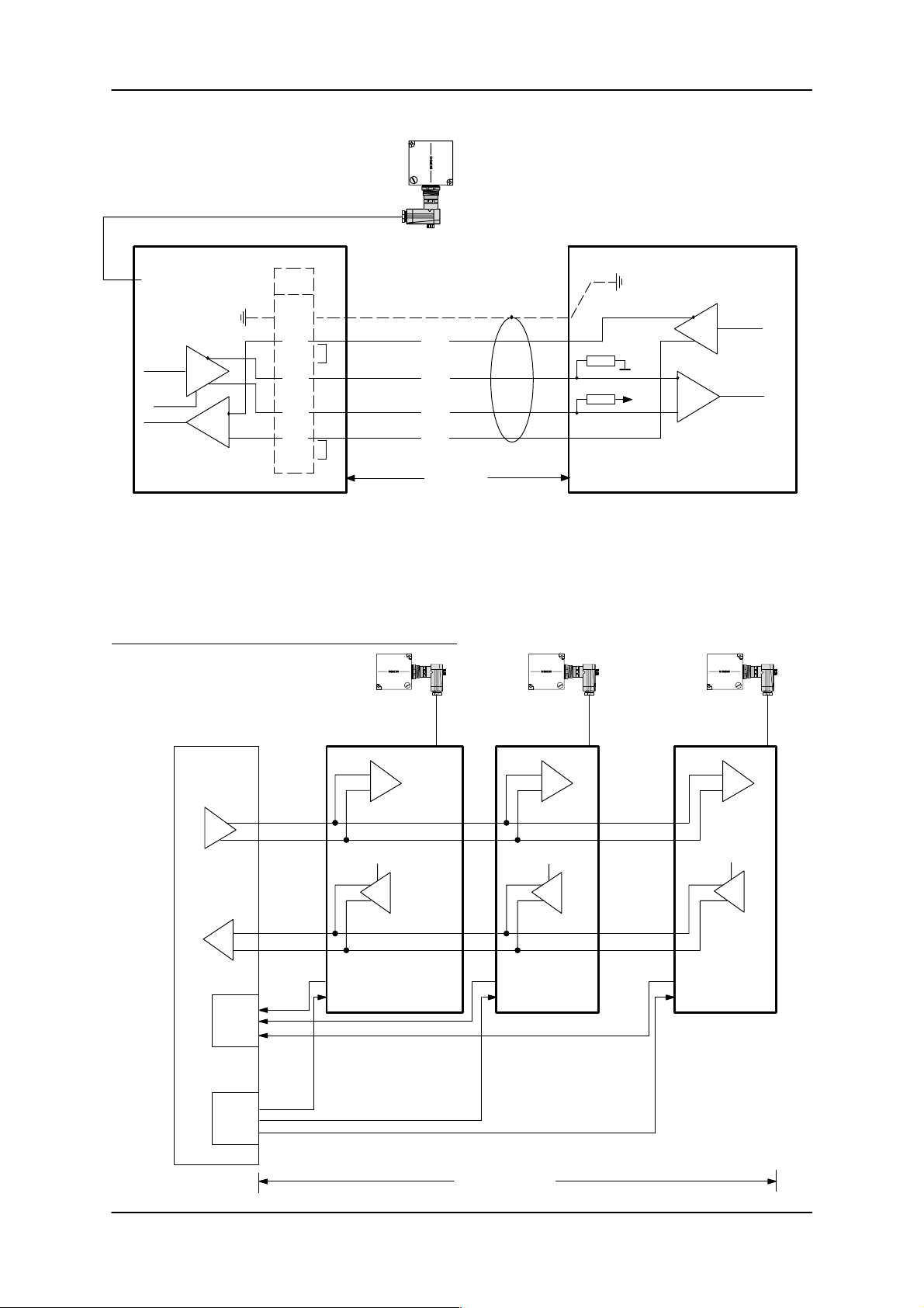
ASM 421 Technical Description 6GT2 097-3AH00-0DA2
2.4.4 RS422 cabling
SLG
ASM 421 Computer
X2
1–9
X1
b30/
z30
TxD
RxD
z8
z6
b8
b6
z4
b4
*)
*)
E–
D–
D+
E+
max.
**)
**)
+5V
length
1000 m
*) The cable can be terminated on the receiving side with jumpers z4 – b4 and z8 – z6. This improves the interference immunity of
the system particularly when long cables are used (i.e., > 200 m). The jumpers may only be wired on the last ASM 421 when daisy
chain operation is used (see chapter 2.4.1).
**) The indicated terminal resistors (R = 200 to 1000 Ohm) must be present on the computer side. These resistors can be wired on
the ASM side when short cables are used. This means jumpers z6 – z8 and b4 – z4 are omitted and 2 jumpers are added
(i.e., b4 – b6 and z6 – b8).
Example of a daisy-chain configuration (see 2.4.1)
SLG
ASM No. 1 ASM No. 2 ASM No. 4
CP
or
computer
z4
+E
z8
Request
dig.
inputs
–E
+D
–D
b6
b8
Enable Enable Enable
b16 b16 b16
z16
Select
dig.
out–
puts
z4
z8
b6
b8
SLG SLG
.......
z4
z4
z8
z8
.......
b6
b6
b8
b8
z16
z16
6GT2 002-0DA00 ASM 421 / V .24
6GT2 002-0DB00 ASM 421 / RS422
6GT2 002-0DC00 ASM 421 / TTY
max. 1000 m
– 15 –
Subject to change without notice!
RD: 03/02
J31069-D0142-U001-A0-7618
Page 18
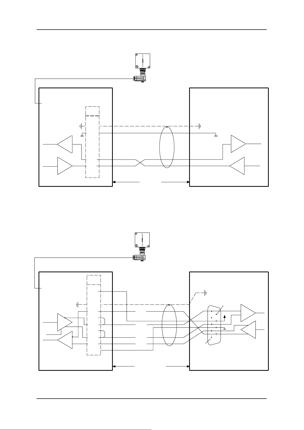
2.4.5 V.24 cabling
ASM 421 Computer
X2
1–9
RxD
ASM 421 Technical Description6GT2 097-3AH00-0DA2
SLG
X1
b30/
z30
b32
RxD
b6
TxD
z4
TxD
max.
length
30 m
V.24 control lines (e.g. DSR, DTR, RTS, CTS) are not supported by the ASM. The acknowledgement of
data is handled by the procedure.
2.4.6 STG cabling
SLG
ASM 421 STG 4F
X2
1–9
TxD
24 V
X1
z2
b30/
z30
z8
z6
b8
E–
D–
9
+
b4
RxD
b6
z4
D+
E+
1
b320V
Test cable
length max.
100 m
The ASM 421 / RS422 can be operated directly with the STG 4F. The complete path from the STG 4F via
the ASM 421 to the SLG will thus be tested.
Subject to change without notice!
RD: 03/02
J31069-D0142-U001-A0-7618
– 16 –
6GT2 002-0DA00 ASM 421 / V .24
6GT2 002-0DB00 ASM 421 / RS422
6GT2 002-0DC00 ASM 421 / TTY
Page 19
ASM 421 Technical Description 6GT2 097-3AH00-0DA2
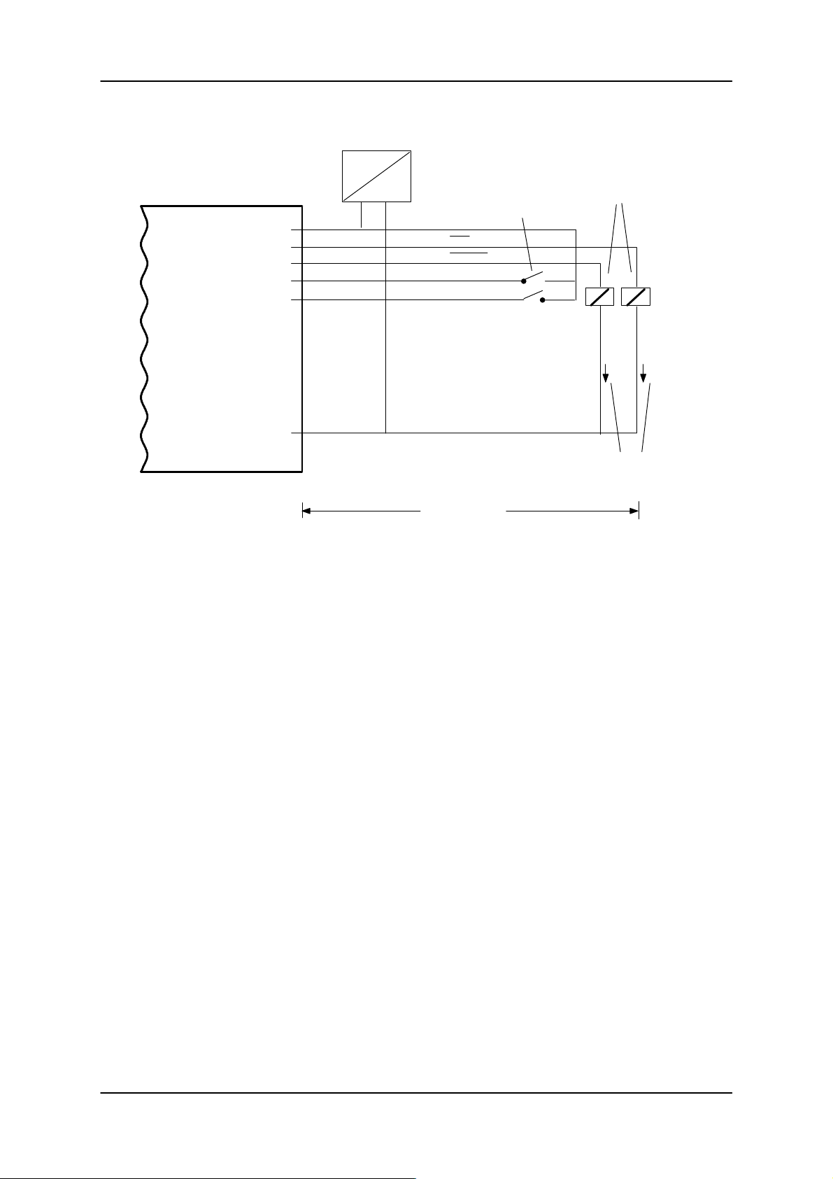
2.4.7 DI/DO cabling
ASM 421
z2
z18
b18
z12
b12
b2
220 V
24 V
=
ANW
Error code
DI 1
DI 0
Cable length
max. 100 m
(shielded or unshielded)
Relay (use break-contact
in load circuit of relay),
horn, lamps, etc.
Proximity switch+–
I
= 200 mA
max
(per DO or
total current)
6GT2 002-0DA00 ASM 421 / V .24
6GT2 002-0DB00 ASM 421 / RS422
6GT2 002-0DC00 ASM 421 / TTY
– 17 –
Subject to change without notice!
RD: 03/02
J31069-D0142-U001-A0-7618
Page 20
ASM 421 Technical Description6GT2 097-3AH00-0DA2
3 Programming the ASM 421 module
3.1 3964R procedure
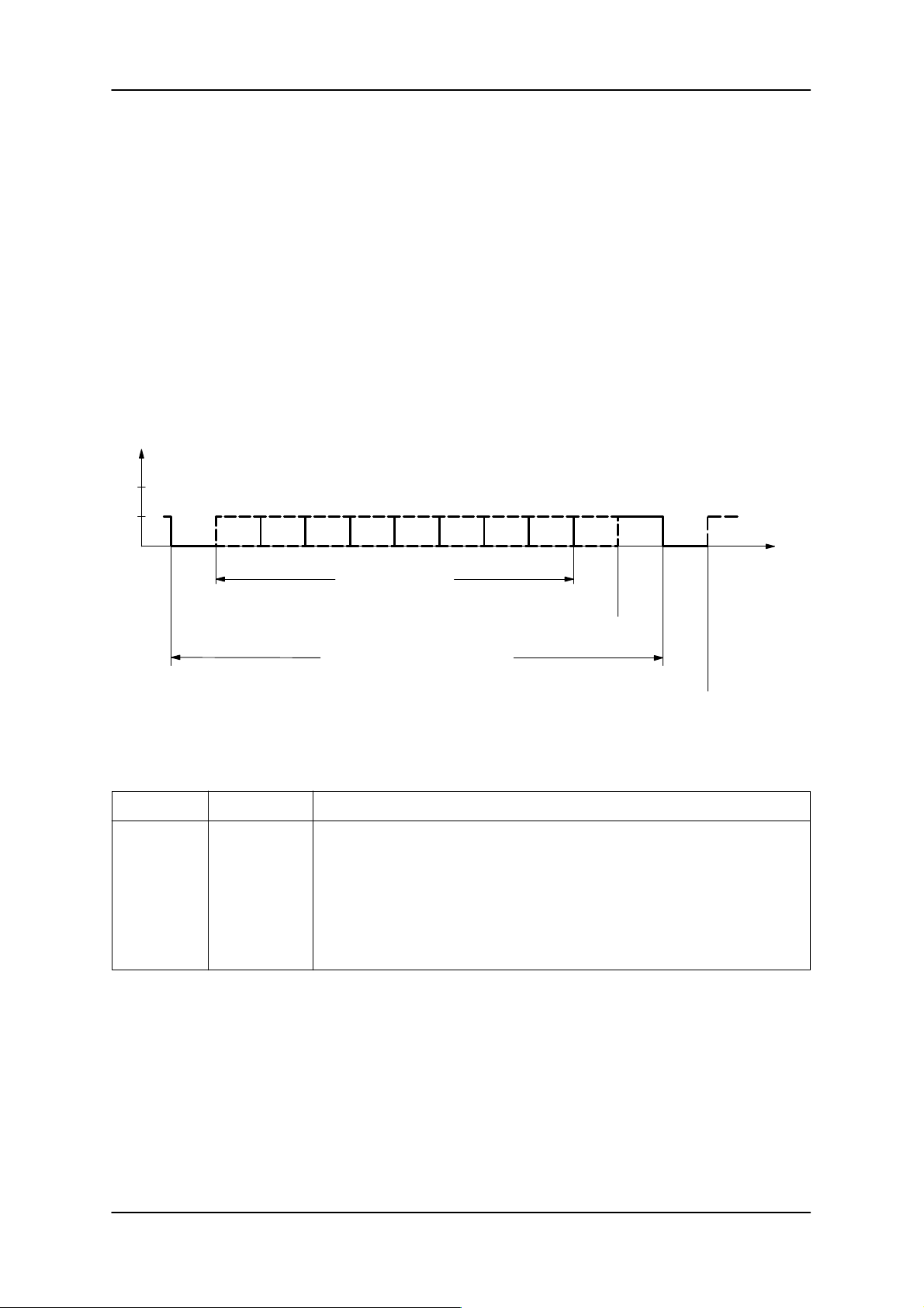
The 3964R procedure provides secure data transmission across a point-to-point connection. Security is
achieved by transmitting the data one block at a time with parity check, block check character (BCC) and
acknowledgement of receipt. All characters from 00hex to FFhex can be present in the data block.
Character frame:
Transmission: asynchronous
Baud rate: 2400, 4800, 9600, 19200 Baud
Data bits: 8
Parity: odd/even (switch selectable)
Stop bit: 1
12345678P
8 data bits
Start step Parity bit
Character frame 11 bits
Control characters in the 3964R procedure:
Character Code (hex) Purpose
STX
DLE ETX
DLE
NAK
02
10 03
10
15
Initialization of a transmit operation (signals ready–to–send)
Marks the end of a transmission block
Ready–to–receive (or DLE duplication in data stream)
Negative response on block–check–error or unrecognized
start character
DLE DLE
10 10
DLE duplication in data block; used if the value 10hex
occurs in the data stream.
t
Next
character
Stop bit
Start step
Subject to change without notice!
RD: 03/02
J31069-D0142-U001-A0-7618
– 18 –
6GT2 002-0DA00 ASM 421 / V .24
6GT2 002-0DB00 ASM 421 / RS422
6GT2 002-0DC00 ASM 421 / TTY
Page 21
ASM 421 Technical Description 6GT2 097-3AH00-0DA2
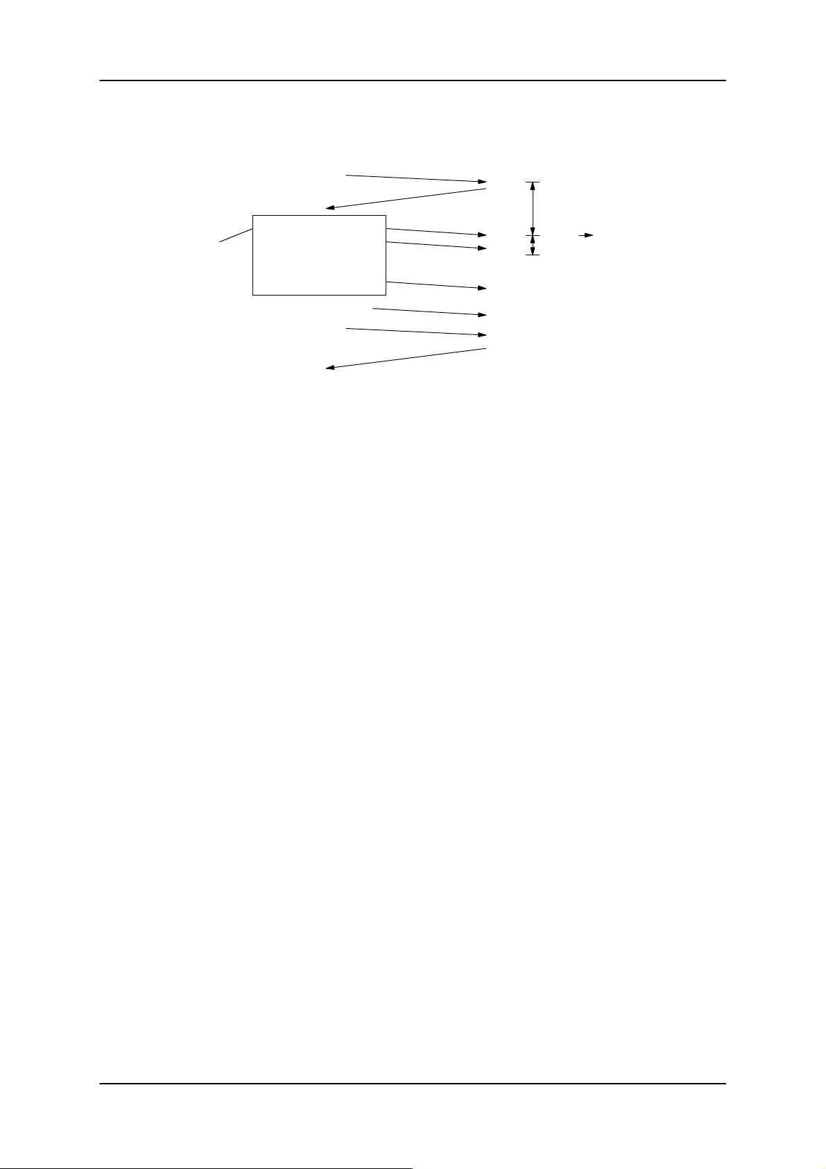
Block Transmission Sequence:
Sender Receiver
STX
DLE
tz= Watchdog
timer on ASM
Data
block
1st user byte
2nd user byte
.
.
.
.
.
.
.
.
t
300 ms
z
last user byte
DLE ETX
BCC
DLE
Data security
To protect data against transmission errors, a parity bit is attached to each character transmitted. It is
supplemented by an odd or even quantity of “ones”. In addition, the sum of the respective bits of each
character in a block is supplemented by a further bit to even parity (EXOR operation on all characters).
The resulting block check character (BCC) is itself secured by the character parity principle and is transmitted at the end of the block. All characters in the block are saved except the start control character STX.
Repeat counter
If no acknowledgement or a negative acknowledgement is received, the telegram will be sent again. The
3964R has a repeat counter. If a block cannot be correctly transmitted after a number of repeats, the transmission will be terminated. The telegram is lost or the user receives an error message.
Initiation conflict
Since both stations have equal rights, an initiation conflict can arise if both partners try to transmit at the
same time. To avoid this, one station is given a higher priority (master) than the other (slave). This can be
set using switch 4 (see section 2.3).
Watchdog timers
Two watchdog timers are used to monitor the data transfer:
– Acknowledgement watchdog timer tQ = 300 ms
The acknowledgement watchdog timer is started after transmission of the control character STX, or
DLE ETX BCC.
If a positive acknowledgement fails to arrive within tQ, the whole data block is sent again. If the transmission has still not been performed correctly after three attempts, an error message is sent to the user
or the telegram is rejected by the ASM and an error indicated by the red LED.
– Character watchdog timer tZ = 300 ms
The receiving ASM 421 monitors the arrival of the individual characters with time constant tz.
If a character fails to arrive within the watchdog period, receiving is aborted and an error indicated by
the red LED.
6GT2 002-0DA00 ASM 421 / V .24
6GT2 002-0DB00 ASM 421 / RS422
6GT2 002-0DC00 ASM 421 / TTY
– 19 –
Subject to change without notice!
RD: 03/02
J31069-D0142-U001-A0-7618
Page 22
ASM 421 Technical Description6GT2 097-3AH00-0DA2
3.2 Telegram format
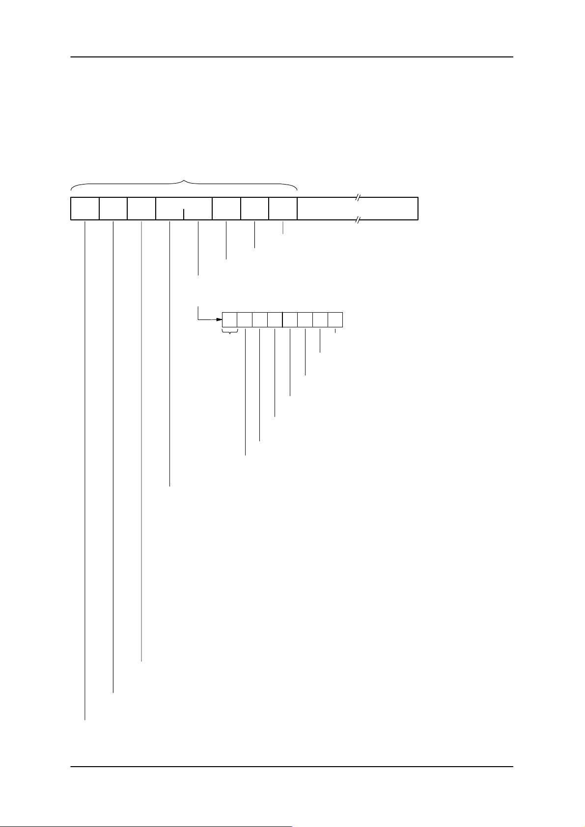
The user communicates with the file handler via telegrams. Telegrams from the user are checked, interpreted and processed by the file handler. The user then receives an acknowledgement telegram containing user data and status information.
The following schematic shows the general telegram format:
Telegram heading (always present)
0 1 2/3 4/5 6/7 8/9 10
res.
ABS
res.
EMPF
res.
LFN
Command
CC CI
Command index
’I’ : MOBY I command from ASM
xx : MOBY I status byte: acknowledgement from ASM
ADB DBN
Total number of data blocks to be transmitted (dual)
DBL User data
The user data depends on the command (see 3.4)
Length of user data following (dual)
Current data block number (dual)
76543210
reserved
(always 00)
1 = The RAM battery is poor or exhausted (always set for
1 = Aux. battery is poor or exhausted (only valid for
MDS 507; otherwise always 1).
1 = WARNING: MDS was outside the transmission window during
command processing.
1 = WARNING: File read had length = 0.
1 = An MDS with a new directory has entered: the bit is set when the file handler
has carried out a read operation on the complete MDS directory. In some
applications, the new directory can be backed up by the MOVE command.
Command code:
’I’ : FORMAT (Format)
’B’ : CREATE (Open file)
’Q’ : QUEUE-WRITE (Set up complete data carrier)
’W’ : WRITE
’U’ : UPDATE (Write complete file)
’R’ : READ
’D’ : DELETE
’Y’ : ATTRIB (Set access rights for a file)
’C’ : COVER (Protect MDS structure)
’G’ : DIR (Read file directory)
’N’ : NEXT (Process next MDS)
’X’ : RESET (Reset file handler)
’F’ : MDS-STATUS (Request MDS status)
’S’ : ASM-STATUS (ASM status request)
’L’ : LOAD (Transmit directory to ASM)
’M’ : MOVE (Read MDS directory out from ASM)
’T’ : TRACE (absolute read)
’H’ : Start-up message from ASM
’Z’ : Special telegram (ANW message)
reserved for sequence number
(The file handler transmits the parameter LFN from the command in the
acknowledgement. It is not evaluated by the file handler)
reserved for receiver recognition*
(presently always 00)
The result of the last command will be delayed by the directory operation.
1 = Command terminated with error; the user
data contains error information.
1 = Only with ECC: data from the MDS has been
corrected and is OK.
EEPROM MDS).
reserved for sender identifier*
(MOBY I: code ’F’ is reserved for STG )
* The file handler interchanges sender and receiver identifiers.
Subject to change without notice!
RD: 03/02
J31069-D0142-U001-A0-7618
– 20 –
6GT2 002-0DA00 ASM 421 / V .24
6GT2 002-0DB00 ASM 421 / RS422
6GT2 002-0DC00 ASM 421 / TTY
Page 23
ASM 421 Technical Description 6GT2 097-3AH00-0DA2
3.3 Blocking of long data sequences
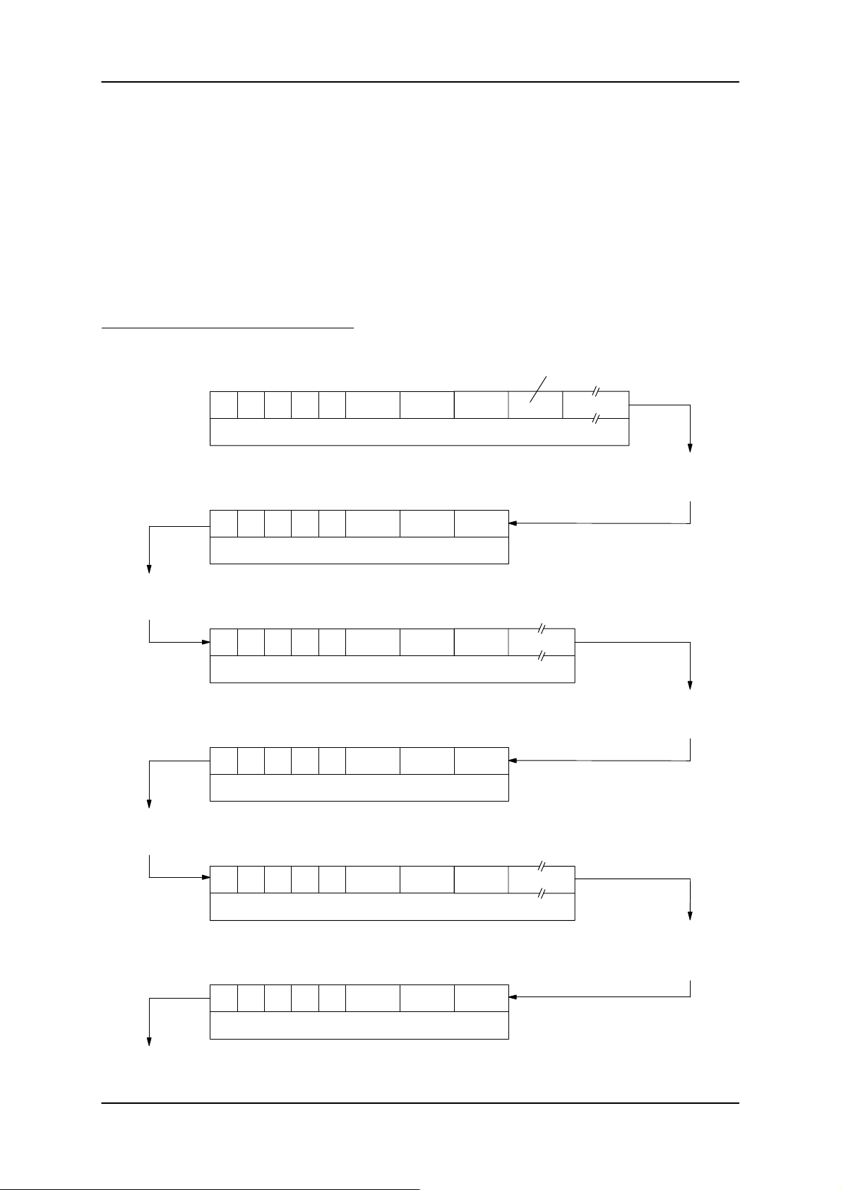
Since it is not possible to work with telegrams of indefinite length, the telegram is formed into blocks, i.e.
telegrams are transmitted in segments.
Blocking can be used with READ, WRITE, UPDATE, QUEUE-WRITE, DIR and TRACE commands.
Blocking is controlled by the parameters ADB (no. of data blocks) and DBN (current data block no.) in the
telegram heading.
The file description immediately follows the DBL parameter in the first command telegram to the file
handler (DBN = 1). It contains the file name, start address and length of the file. The file description is
omitted from subsequent telegram segments (DBN > 1).
Schematic sequence (example WRITE):
File description
CC CI ADB DBN DBL
’I’ 0003 User data
1st command telegram from user to ASM
The command consists of three telegram segments
CC CI ADB DBN DBL
00 0003
0001
0001
Processing of 1st telegram
segment by the file handler on
the ASM 421
00
1st acknowledgement telegram from ASM to user
The user processes the acknowledgement and issues the 2nd
command segment
2nd acknowledgement telegram from ASM to user
The user processes the acknowledgement and issues the 3rd
command segment
CC CI ADB
’I’ 0003 User data
2nd command telegram from user to ASM
CC CI
CC CI
3rd or last command telegram from user to ASM
CC
ADB DBN DBL
00 0003
ADB DBN DBL
’I’ 0003
CI ADB DBN DBL
0003
00 00
DBN DBL
0002
0002
0003 User data
0003
00
Processing of 2nd telegram
segment by the file handler on
the ASM 421
Processing of last telegram
segment and terminating the
command by the file handler on
the ASM 421
3rd or last acknowledgement tel. from ASM to user
The command has been
processed
6GT2 002-0DA00 ASM 421 / V .24
6GT2 002-0DB00 ASM 421 / RS422
6GT2 002-0DC00 ASM 421 / TTY
– 21 –
Subject to change without notice!
RD: 03/02
J31069-D0142-U001-A0-7618
Page 24
ASM 421 Technical Description6GT2 097-3AH00-0DA2
The maximum block length (maximum length of a telegram segment) can be set using the RESET command. The default value for the block length is 128. The maximum block length that can be set is 255.
The blocking sequence can be aborted using the RESET command. The blocking sequence will be ended. No further acknowledgement of the aborted command will be issued.
All other commands within a blocking sequence will be rejected by the ASM 421 with an error message.
The present status of the blocking sequence remains unchanged.
3.4 File handler commands
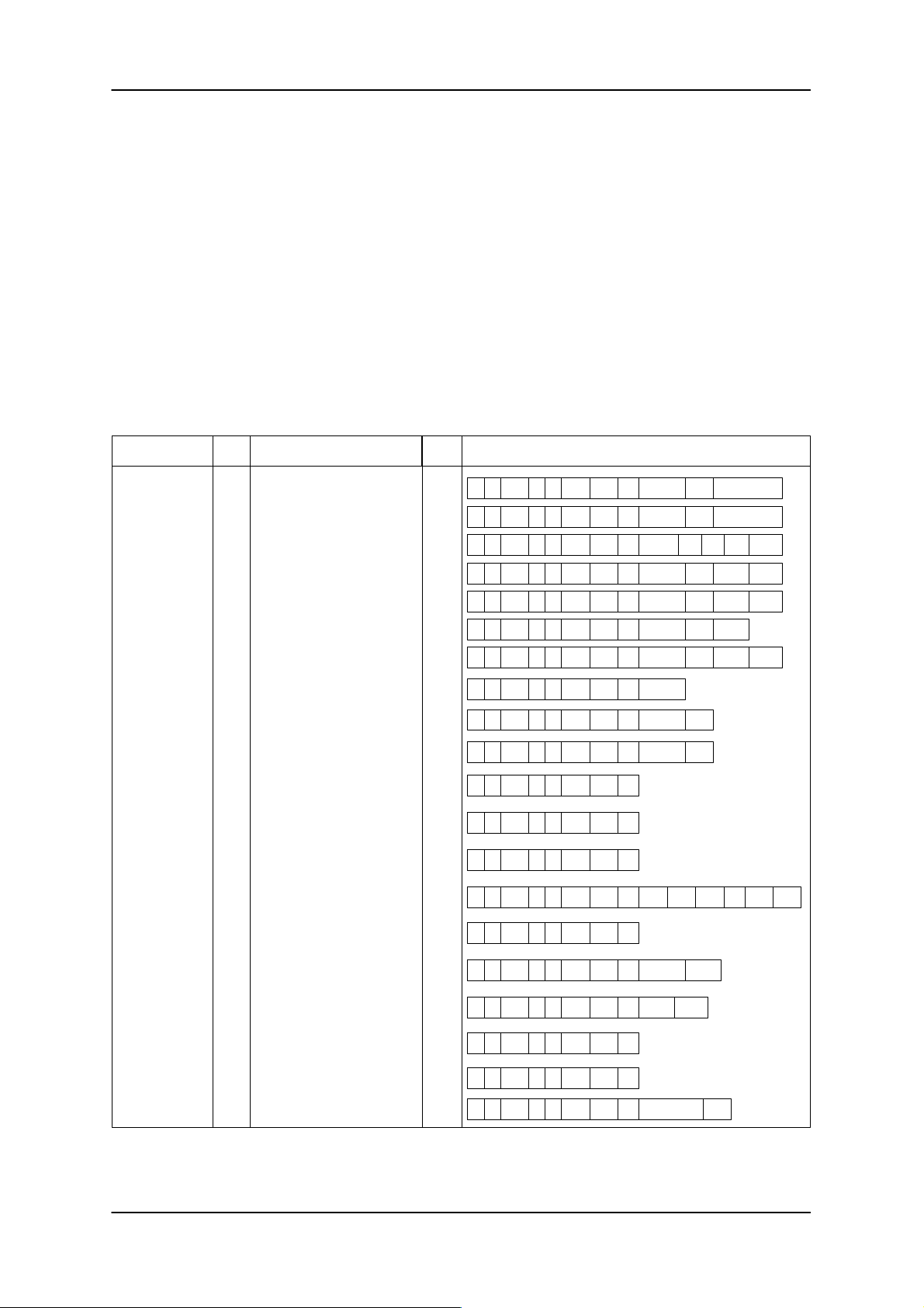
The following table lists all file handler commands
Command CC Purpose Prio
FORMAT
CREATE Create file on MDSB
Format and initialize MDS
ID
WD
W
WDWRITE Write part or complete file
UWDUPDATE Update complete file
RREAD Read data from file
RWD
RWDEQUEUE-READ Read complete data medium
WDYATTRIB Set file attribute
DCCOVER Protect MDS structure
RWDGDIR Read MDS directory
RWDSASM-ST ATUS Read ASM status
RWDFMDS-STA TUS Read MDS status
RWDXRESET Reset command to ASM
*
Telegram format (to ASM)
00 00 0000 ’I’ 0001 0001 0C Volume Type Parameter’I’
00 00 0000 ’B’ 0001 0001 0C F.name Attr. res. length’I’
00 00 0000 ’Q’ ADB 0001 DBL Option Res Leng’I’ DataRes
DQUEUE-WRITE Set up complete data carrierQ
00 00 0000 ’W’ ADB 0001 DBL F.name Adr. Leng.’I’ Data
00 00 0000 ’U’ ADB 0001 DBL F.name Adr. Leng.’I’ Data
00 00 0000 ’R’ 0001 0001 0E F.name Adr. Leng.’I’
xx 00 0000 ’E’ 0001 0001 DBL Option Res Leng.’I’ Data
00 00 0000 ’D’ 0001 0001 08 F.name’I’
DDDELETE Delete file
00 00 0000 ’Y’ 0001 0001 09 F.name Attr.’I’
00 00 0000 ’C’ 0001 0001 09 Volume User’I’
00 00 0000 ’G’ 0001 0001 00’I’
00 00 0000 ’S’ 0001 0001 00’I’
00 00 0000 ’F’ 0001 0001 00’I’
00 00 0000 ’X’ 0001 0001 07’I’
Mode EAKO ECC No. Prior. Reg.
00 00 0000 ’N’ 0001 0001 00’I’
RWDNNEXT Process the next MDS
00 00 0000 ’T’ 0001 0001 06 Startadr’I’ Leng.
RWDTTRACE MDS absolute read
LRWDLOAD Transmit directory to ASM
MRWDMOVE Retrieve directory from ASM
00 00 0000 ’L’ ADB 0001 DBL Leng.’I’ Data
00 00 0000 ’M’ 0001 0001 00’I’
00 00 0000 ’H’ 0001 0001 0000 **
RWDHStartup message Reported by ASM when
power returns
00 00 0000 ’Z’ 0001 0001 05 00 00 00 00 ANW00
RWDZPresence Proximity message from ASM
* The priority and access rights of the interface module are switch selectable (see section 2.3).
** This message is from ASM only. Switch 8 must be on as described in section 2.3.
Subject to change without notice!
RD: 03/02
J31069-D0142-U001-A0-7618
– 22 –
6GT2 002-0DA00 ASM 421 / V .24
6GT2 002-0DB00 ASM 421 / RS422
6GT2 002-0DC00 ASM 421 / TTY
**
Page 25
ASM 421 Technical Description 6GT2 097-3AH00-0DA2
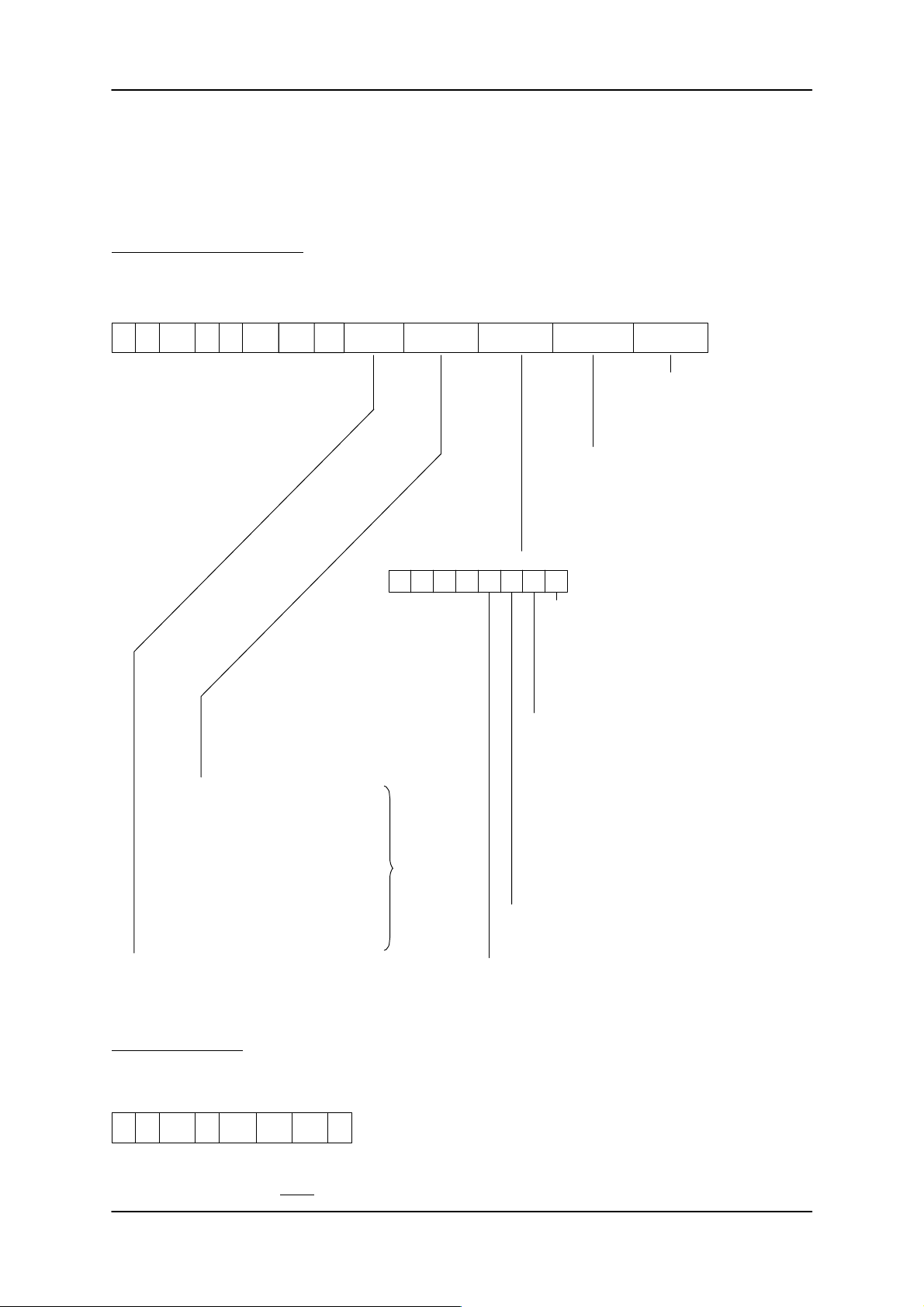
3.4.1 FORMAT
The FORMAT command erases the complete MDS. The directory, file allocation table (FAT) and system
area on the MDS will be re-created. Some counter contents in the system area will be retained. The current counter contents can be interrogated by the MDS STATUS command.
Telegram to the file handler:
0 1 2/3 4 5 6/7 8/9 10 11/18 19 20 21 22
CC CI ADB DBN DBL
xx 00 0000 0001 0CH Volume MDS type OPTIONS INIT mode INIT value
’I’
’I’ 0001
The complete MDS will be erased
and written with this data if the
parameter ‘INIT mode’ has the value
‘L’.
’K’ = Not initialized; only DIR and FAT will be
re-created o n the MDS. The old user data
remains physically in memory.
‘L’ = Initialized; the whole MDS will be written
with the data in ‘INIT value’.
01H = 62 bytes without ECC
81H = 42 bytes with ECC
02H = 62 bytes without ECC
03H = 128 bytes without ECC
83H = 112 bytes with ECC
04H = 2045 bytes without ECC
84H = 1778 bytes with ECC
05H = 8189 bytes without ECC
85H = 7154 bytes with ECC
06H = 32765 bytes without ECC
86H = 28658 bytes with ECC
MDS name; 8 ASCII characters (20H-7EH)
76543210Bit
0000
See table
in Chapter 1
0 = Always read DIR and FAT completely
when this MDS enters the field.
1 = Check sum mechanism enabled; DIR
and FAT are only read if the checksum
in the interface module does not
correspond with the checksum in the
MDS.
0 = Complete old directory will be erased
(normal)
1 = The old directory in the MDS will be
re-created in the MDS. The existing user
data lengths of the files remain unchanged.
The user data area will be over-written by
the specified data.
The directory to be formatted can also be
loaded into the ASM immediately before
the start of the format command by use of
the ’L’ command (this option is only
meaningful if the INIT mode parameter
(byte 21) is set to ’L ’).
0 = Complete MDS will be erased
1 = DIR + FAT are erased; the user data is
preserved
0 = Normal
1 = The counters for write cycles or ECC offsets are
always retained. The counters are also retained even
when the system area is faulty (e.g., ECC error).
Acknowledgement:
0 1 2/3 4 5 6/7 8/9 10
CC Status ADB DBN DBL
00 xx 0000 0001
’I’
00 0001 00
Important: A new MDS must be formatted before being used in the system.
6GT2 002-0DA00 ASM 421 / V .24
6GT2 002-0DB00 ASM 421 / RS422
6GT2 002-0DC00 ASM 421 / TTY
– 23 –
Subject to change without notice!
RD: 03/02
J31069-D0142-U001-A0-7618
Page 26
ASM 421 Technical Description6GT2 097-3AH00-0DA2
3.4.2 CREATE
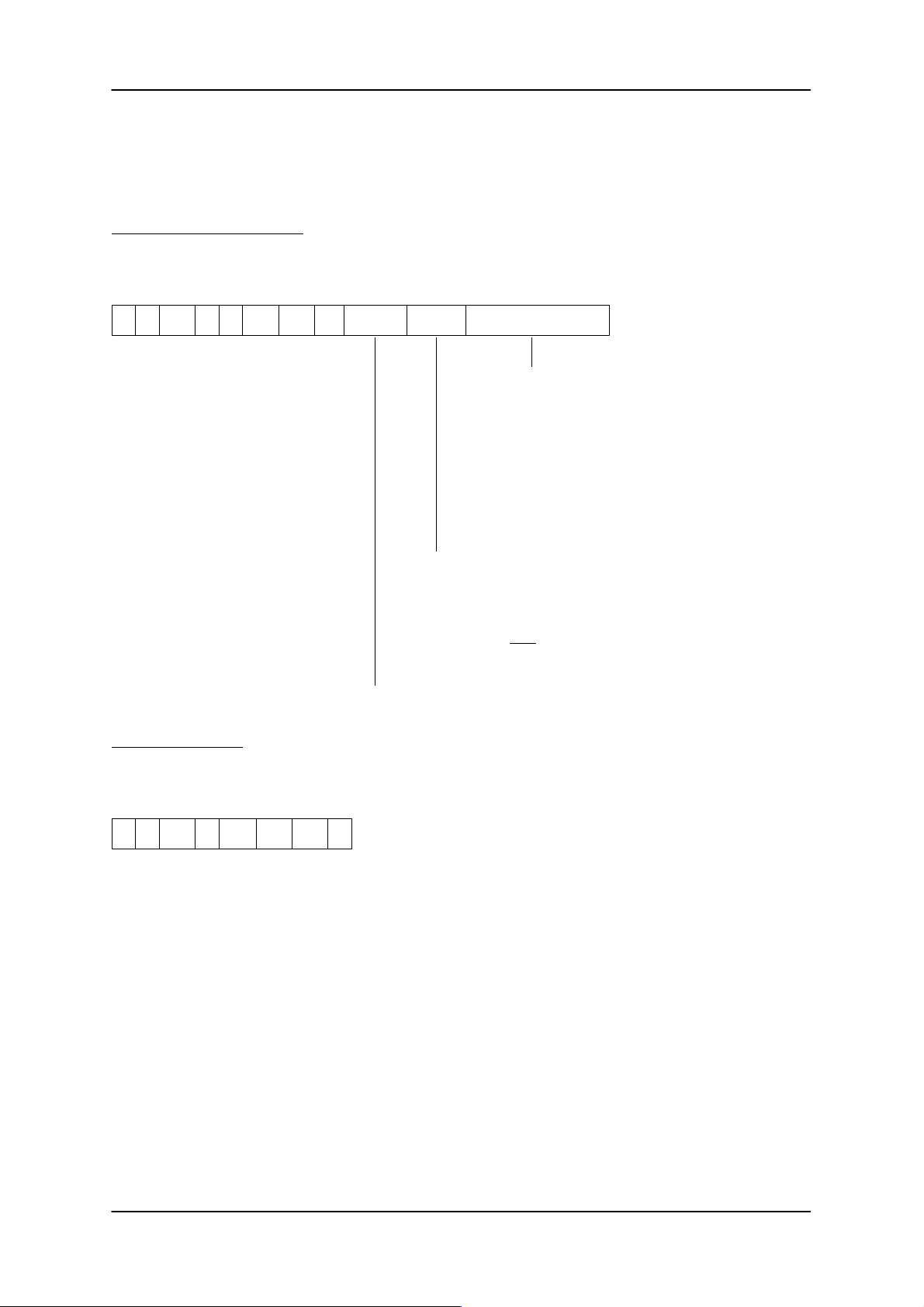
A new file is established on the MDS by the CREATE command. An entry will be made in the MDS directory for each CREATE command. DIR and FAT in the MDS will be updated.
Telegram to the file handler:
0 1 2/3 4 5 6/7 8/9 10 11/18 19 20/22
CC CI ADB DBN DBL
xx 00 0000 0001 0CH F.name Attribute Data length to be res.
’B’
’I’ 0001
The file handler reserves the file length given here. If
000000H is given as the data length, the file handler
reserves a block as standard procedure.
Note:
Specification of a data length is not mandatory . If the data
written later exceeds the data length given here, the file
handler will automatically reserve more memory for the
file. MDS memory is managed dynamically by the file
handler.
Acknowledgement:
0 1 2/3 4 5 6/7 8/9 10
CC Status ADB DBN DBL
00 xx 0000 0001
’B’
00 0001 00
Setting of access rights for this file:
00H → No attribute
01H → Read only; the file can only be read
02H → Write once; the data may only be written once. New data can
be appended. The file cannot be erased with DELETE. The
data must be written using the automatic append function.
File name; 8 ASCII characters (20H - 7EH)
Subject to change without notice!
RD: 03/02
J31069-D0142-U001-A0-7618
– 24 –
6GT2 002-0DA00 ASM 421 / V .24
6GT2 002-0DB00 ASM 421 / RS422
6GT2 002-0DC00 ASM 421 / TTY
Page 27
ASM 421 Technical Description 6GT2 097-3AH00-0DA2
3.4.3 QUEUE-WRITE
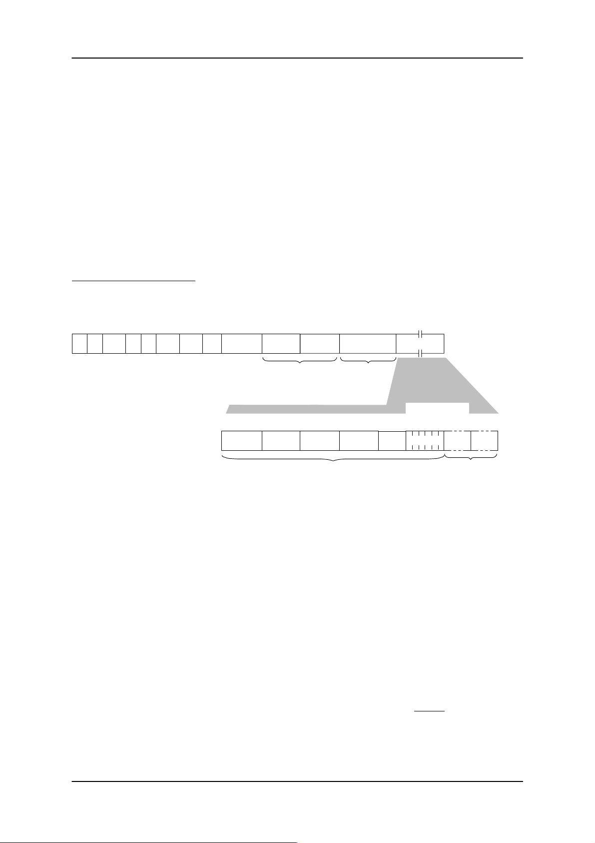
This command combines several WRITE commands into one command. This gives you the following
advantages:
1. Writing of several files is faster since writing is not dependent on the serial transmission to the ASM.
2. The files are provided with a fixed length.
3. Filling in any pattern is possible.
4. Attributes can be assigned.
This function cannot be executed unless the addressed MDS has been formatted correctly. In addition,
this command is aborted with error message C006 if the addressed MDS leaves the transmission window
prematurely (handling same as for the FORMAT command).
Telegram to the file handler:
0 1 2/3 4 5 6/7 8/9 10 11–12 22–24
CC CI ADB DBN DBL
xx 00 0000 ADB DBL Option xxxxxxxx
Option: The following applies if the data carrier already contains an existing file structure:
File name: File name
Attribute: Attribute for this file. The attribute is not set until the data have been written.
Reserved: 1 byte is reserved.
’Q’
’I’ 0001 xxxxxx
8 bytes 1 byte 3 bytes 1 byte 1 byte
File name Attribute
Option = 0000H: The file structure is overwritten or deleted with the QUEUE-WRITE
Option = 0001H: The file structure is added to the existing file structure with the
13–18 19–21 25 ...
Length of the
file entries
Disregard For WRITE:
Length
Data entry
command.
QUEUE-WRITE command. A check is made to determine whether the file
to be set up already exists.
length of
the user
data
Reserved
File entries
Number of bytes
corresponds to
“length”
Skip
Data
Additional data entries
Skip: Skip specifies how many bytes are between the previous file entry and the next file entry.
Length: Length in bytes of the subsequent data for the specified file.
Data: The data to be written. These data can also be a filling pattern. The amount of data in bytes must
Example: skip = 00hex (i.e., the file name of the next file entry immediately follows the data of the
previous file entry).
correspond to the “length” parameter.
Note: 1. The start address of the QUEUE-WRITE command always starts at the
address 000000 hex in the respective file.
2. One block is always reserved by the file handler if the length is 0 hex.
Since the file entry does not contain data when the length = 0, the
QUEUE-WRITE command corresponds to a multiple execution of the
CREATE command in this case.
6GT2 002-0DA00 ASM 421 / V .24
6GT2 002-0DB00 ASM 421 / RS422
6GT2 002-0DC00 ASM 421 / TTY
– 25 –
Subject to change without notice!
RD: 03/02
J31069-D0142-U001-A0-7618
Page 28

ASM 421 Technical Description6GT2 097-3AH00-0DA2
Acknowledgement:
0 1 2/3 4 5 6/7 8/9 10
CC Status ADB DBN DBL
00 xx 0000 ADB
’Q’
00 0001 00
Handling of Errors:
If the file handler detects a syntax error in the structure of the transmitted file entry, the QUEUE-WRITE
command is aborted with an appropriate error message. In addition, the QUEUE-WRITE command is
aborted with the option = 0001 hex if the file handler determines that the file to be set up already exists.
Error Identification for Parameter Error in File Entry:
K xxx
“xxx” stands for the number of the file entry in which an error was found. Counting of the file entries begins
with 1.
Example: Error message “K002” → Error in the second file entry.
Subject to change without notice!
RD: 03/02
J31069-D0142-U001-A0-7618
– 26 –
6GT2 002-0DA00 ASM 421 / V .24
6GT2 002-0DB00 ASM 421 / RS422
6GT2 002-0DC00 ASM 421 / TTY
Page 29
ASM 421 Technical Description 6GT2 097-3AH00-0DA2
3.4.4 WRITE/UPDATE
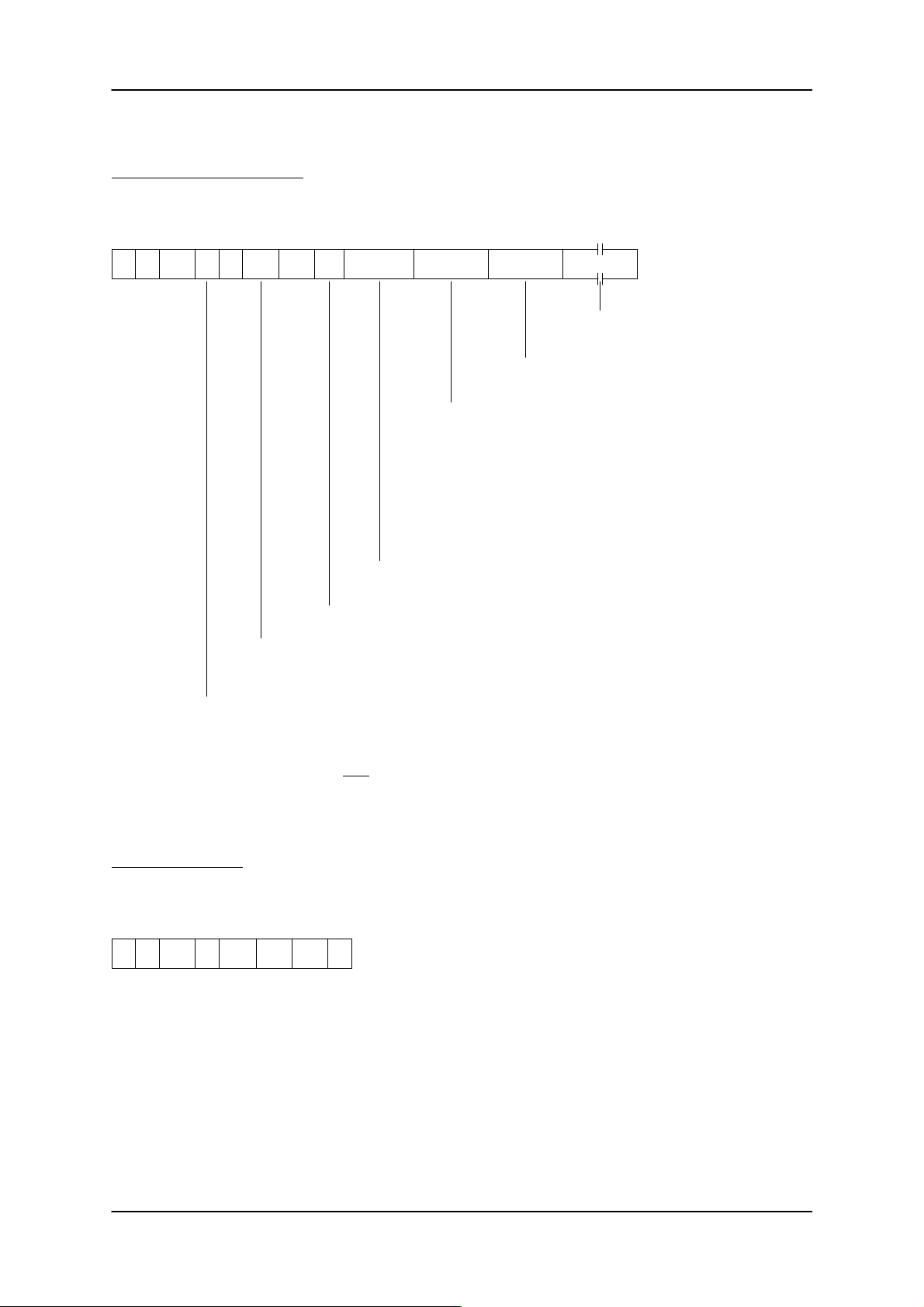
Telegram to the file handler:
0 1 2/3 4 5 6/7 8/9 10 11/18 19/21 22/24 25..254
CC CI ADB DBN DBL
xx 00 0000 ADB DBL File name Start addr. Length Data
’W’
’I’ 0001
’U’
User data in any format
Total length of data to be written (no. of bytes in hex
format)
Offset address within the file:
000000 → Normal write command for the complete file.
xxxxxx → Only part of the existing file is to be overwritten. The start
address must remain within the bounds of the existing
file.
FFFFFF → The automatic append function is activated by the start
address –1. New data will be appended to the existing
file.
Length of the data following in the telegram
Number of command segments for the write command. The
user must calculate ADB correctly.
’W’ → WRITE: All or only part of a file can be written with the write
’U’ → UPDATE: The UPDATE command always writes a complete file.
command. If only part of the file is written, old file data will
remain at the beginning or end of the file.
The start address must always be given a value of 000000. If the
new file data is shorter than the old data, the new file has the
length of the new data. The memory already reserved for this
file nevertheless remains.
Acknowledgement:
0 1 2/3 4 5 6/7 8/9 10
CC Status ADB DBN DBL
00 xx 0000 ADB
’W’
00 0001 00
’U’
File name; 8 ASCII characters (20H-7EH)
The file must already be entered in the directory.
6GT2 002-0DA00 ASM 421 / V .24
6GT2 002-0DB00 ASM 421 / RS422
6GT2 002-0DC00 ASM 421 / TTY
– 27 –
Subject to change without notice!
RD: 03/02
J31069-D0142-U001-A0-7618
Page 30
ASM 421 Technical Description6GT2 097-3AH00-0DA2
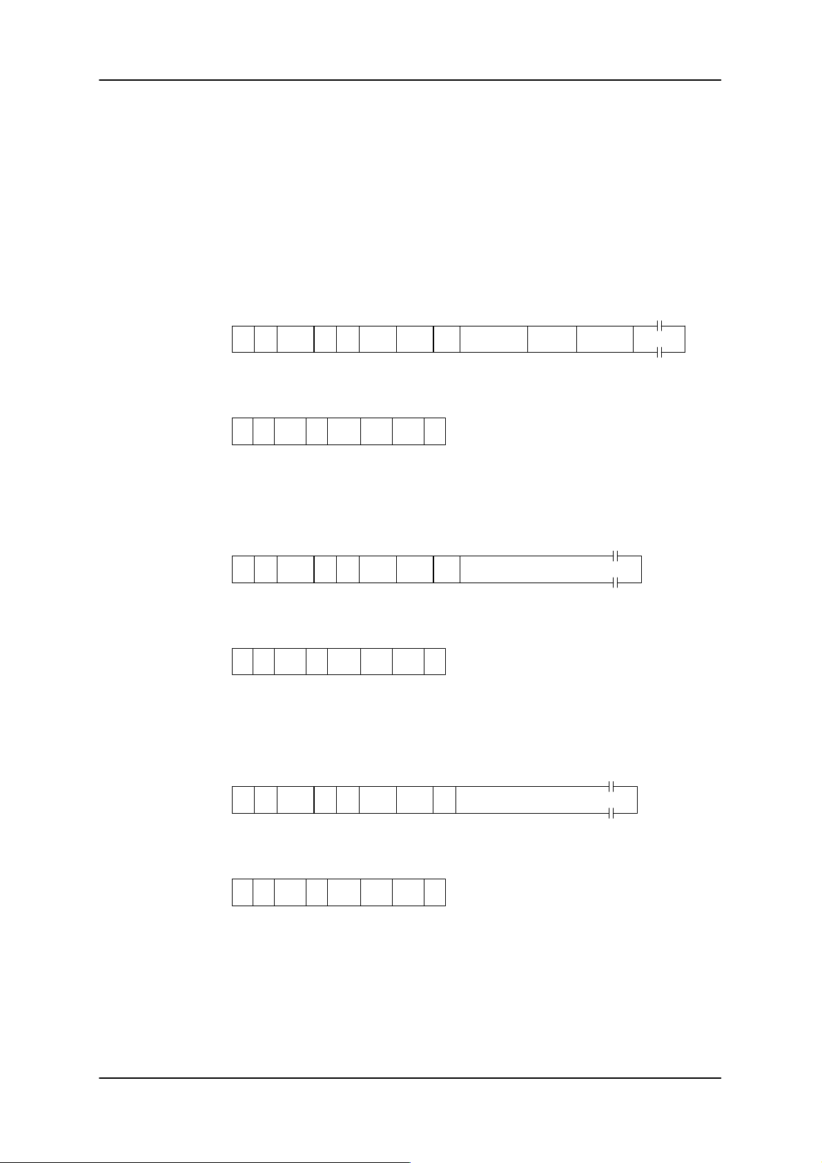
Example:
The file ‘EXAMPLE’ is to be written from position 0 with a length of 500 bytes. Assumption: the file already
exists, there is enough free memory available on the MDS and the write operation will be performed without error. 514 bytes of user data are to be transmitted (500 + 14 for name, start address, length).
The block length specified as 255 bytes results in 3 telegram segments with user data lengths of 230, 244
and 26 bytes.
1st telegram
segment to file
handler:
Acknowledgement:
2nd telegram
segment to file
handler:
Acknowledgement:
0 1 2/3 4 5 6/7 8/9 10
CC CI ADB DBN DBL
xx 00 0000 0003
0 1 2/3 4 5 6/7 8/9 10
00 xx 0000 0003
0 1 2/3 4 5 6/7 8/9 10
xx 00 0000 0003
0 1 2/3 4 5 6/7 8/9 10
00 xx 0000 0003
’W’
CC Status ADB DBN DBL
’W’
00 0001 00
CC CI ADB DBN DBL
’W’
CC Status ADB DBN DBL
’W’
00 0002 00
0001 F4H’I’ ’EXAMPLE’ 000000 0001F4H xx xx
0002 F4H’I’ xx xx xx xx xx xx xx xx xx xx
11/18 19/21 22/24 25..254
File name Start addr Length Data (230 bytes)
11..254
Data (244 bytes)
3rd telegram
segment to file
handler:
Acknowledgement:
Subject to change without notice!
RD: 03/02
J31069-D0142-U001-A0-7618
0 1 2/3 4 5 6/7 8/9 10
CC CI ADB DBN DBL
xx 00 0000 0003
0 1 2/3 4 5 6/7 8/9 10
00 xx 0000 0003
’W’
CC Status ADB DBN DBL
'W'
00 0003 00
0003’I’ xx xx xx xx xx xx xx xx xx xx
– 28 –
11..36
Data (26 bytes)
1A
6GT2 002-0DA00 ASM 421 / V .24
6GT2 002-0DB00 ASM 421 / RS422
6GT2 002-0DC00 ASM 421 / TTY
Page 31
ASM 421 Technical Description 6GT2 097-3AH00-0DA2
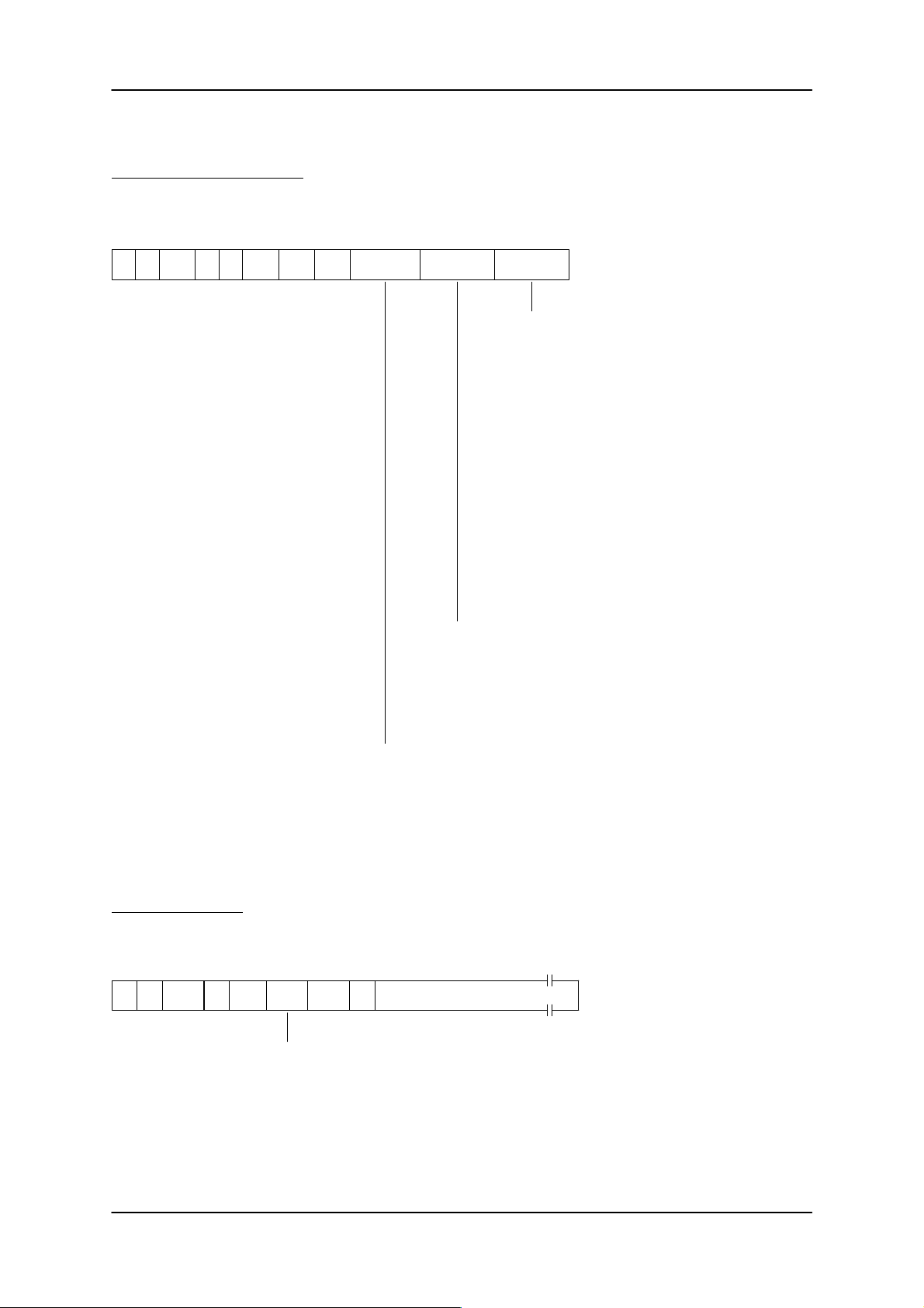
3.4.5 READ
Telegram to the file handler:
0 1 2/3 4 5 6/7 8/9 10 11/18 19/21 22/24
CC CI ADB DBN DBL
xx 00 0000 File name Start addr. Length
’R’
’I’ 0001 0E
0001
*
*
Length of file data to be read (in bytes)
000000 → The presence of the file in the directory is
xxxxxx → The amount of data specified here is read
FFFFFF → If a length of –1 is passed, the file handler
Offset address within the file (hex).
A data file always begins at address 000000. If only a part of the file
is read in order to give rapid access to important MDS data, the start
address can be set here.
Important: The start address must lie within the bounds of the
existing file.
File name; 8 ASCII characters (20H-7EH)
checked. No data are transmitted to the
user. If the file is not present, an error
message results.
from the MDS. If the MDS does not
contain as much data as specified here,
the actual amount of data is transmitted
to the user in the DBL and a WARNING
is set in the status byte.
reads the complete file. (The start
address must be given a value of
000000). The actual data length will be
passed to the user in the DBL parameter.
If a start address not equal to 000000 is
entered, the file handler reads the file
from the specified address to the end of
file.
* Important: A value of 0001H must always be entered for the parameters ADB and DBN in the first
telegram of a read command. The file handler calculates the actual number of ADBs and
sends this to the user in the first acknowledgement telegram (see example on the next
page).
Acknowledgement:
0 1 2/3 4 5 6/7 8/9 10
CC Status ADB DBN DBL
00 xx 0000 xxxx
6GT2 002-0DA00 ASM 421 / V .24
6GT2 002-0DB00 ASM 421 / RS422
6GT2 002-0DC00 ASM 421 / TTY
’R’
000100 xx xx xx xx xx xx xx xx xx xx
The actual number of telegram segments for this read
operation is passed to the user here.
DBL
11/255
Data
– 29 –
Subject to change without notice!
RD: 03/02
J31069-D0142-U001-A0-7618
Page 32
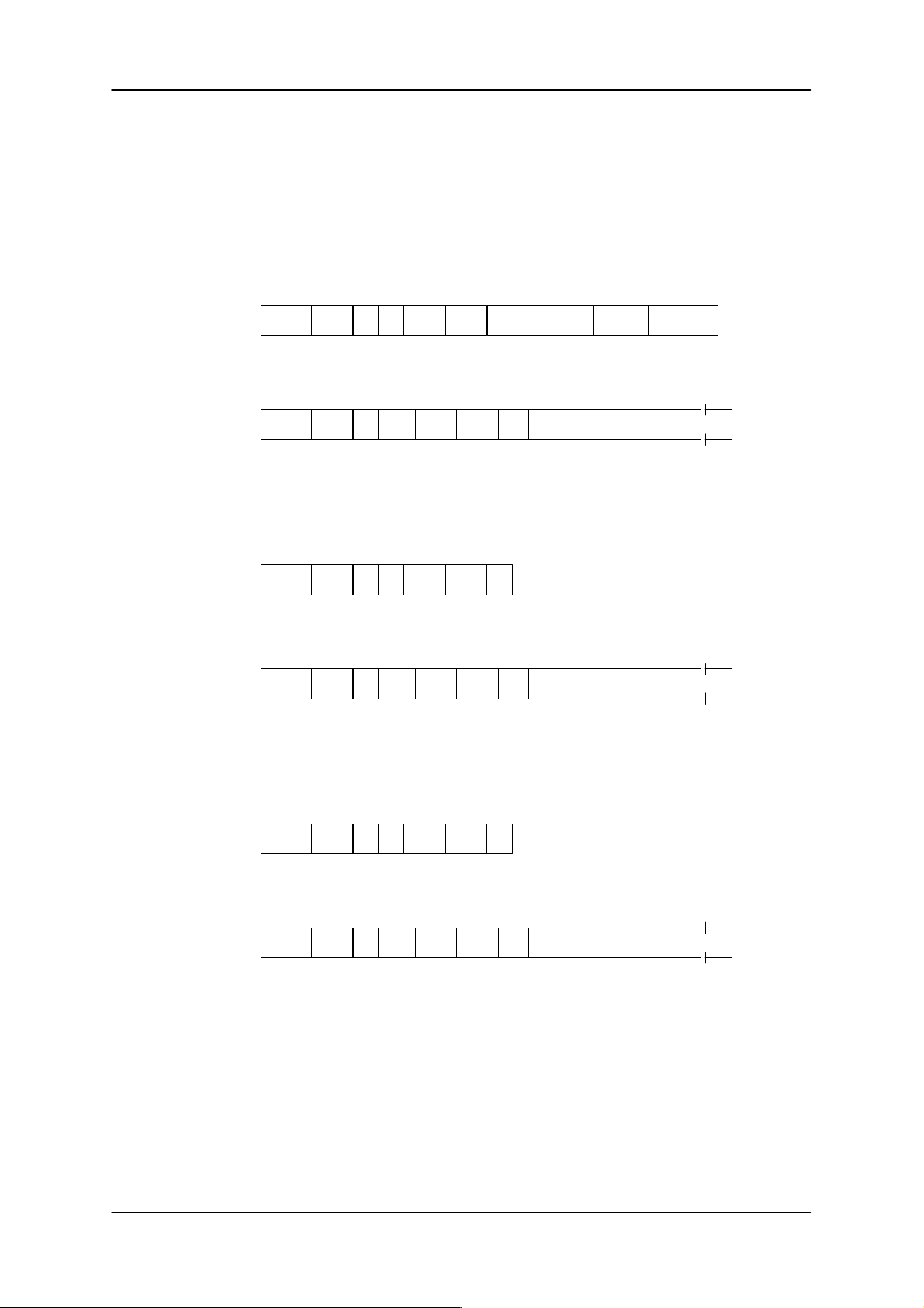
Example:
The file ‘EXAMPLE’ is to be read from the MDS.
Assumptions: the file exists and the exact length is not known.
ASM 421 Technical Description6GT2 097-3AH00-0DA2
1st telegram
segment to file
handler:
Acknowledgement:
2nd telegram
segment to file
handler:
Acknowledgement:
0 1 2/3 4 5 6/7 8/9 10
CC CI ADB DBN DBL
xx 00 0000 0001
0 1 2/3 4 5 6/7 8/9 10
00 xx 0000 0003
0 1 2/3 4 5 6/7 8/9 10
xx 00 0000 0003
0 1 2/3 4 5 6/7 8/9 10
xx 00 0000 0003
’R’
CC Status ADB DBN DBL
’R’
CC CI ADB DBN DBL
’R’
CC Status ADB DBN DBL
’R’
0001 0EH’I’ ’EXAMPLE’ 000000 FFFFFFH
0001 F4H00 xx xx xx xx xx xx xx xx xx xx
0002 00’I’
0002 F4H00 xx xx xx xx xx xx xx xx xx xx
11/18 19/21 22/24
File name Start addr. Length
11..254
Data (244 bytes)
11..254
Data (244 bytes)
3rd telegram
segment to file
handler:
Acknowledgement:
0 1 2/3 4 5 6/7 8/9 10
CC CI ADB DBN DBL
xx 00 0000 0003
0 1 2/3 4 5 6/7 8/9 10
00 xx 0000 0003
’R’
CC Status ADB DBN DBL
’R’
0003 00’I’
0003 0CH00 xx xx xx xx xx xx xx xx xx xx
11..22
Data (12 bytes)
The total file length can be calculated by the user from the sum of all DBLs:
F4H + F4H + 0CH = 1F4H → decimal: 500 bytes
Subject to change without notice!
RD: 03/02
J31069-D0142-U001-A0-7618
– 30 –
6GT2 002-0DA00 ASM 421 / V .24
6GT2 002-0DB00 ASM 421 / RS422
6GT2 002-0DC00 ASM 421 / TTY
Page 33
ASM 421 Technical Description 6GT2 097-3AH00-0DA2
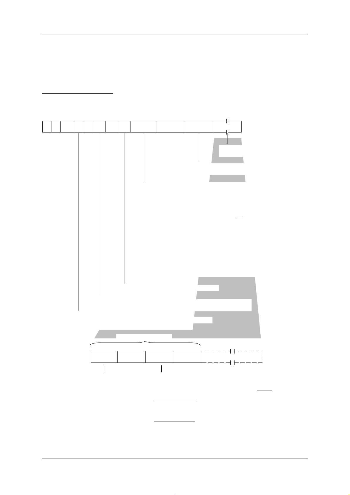
3.4.6 QUEUE-READ
The QUEUE-READ command is used to read several files (max. of 15) with one command from the MDS.
The complete MDS with all files can also be read as an option.
Telegram to the filehandler:
0 1 2/3 4 5 6/7 8/9 10 11/12 13/21 22/24 25..254
KK KI ADB DBN DBL
xx 00 0000 0001 DBL Option In reserve Length Data
'E'
'I' 0001
The user data contain the files to be read
(max. of 16 file entries).
Length of the subsequent data
starting at byte 25 (in hex format)
0000 No option. The data contain the files to be read.
0001 (Res. for QUEUE-WRITE)
0002 All files of the MDS are read. No data starting at byte 25.
Length is 000000 (bytes 22 to 24).
0004 If the actual file length is longer than the file length reserved in the data,
no error message is generated.
0008 The user data contain the files that are not to be read. This means that
all files of the data memory are read except the files specified in the
command. The “length” parameter in the file entry can be disregarded
for this option.
0010 The read file data are organized by word and are directly appended to
each other. This means that a skip byte with the value 20hex is added to
odd length files. The “skip” parameter has the value 0001 in the acknowledgment. With this option “length” must always be set to FFFFFF in the
file entries.
The options are bit-coded. Several options can be set at the same time.
Example: 000C, 0012, 0018, and so on.
Length of the subsequent data in the telegram
Number of subcommands is always 0001 with the command. The filehandler
supplies the correct number (ADB) in the first acknowledgment telegram.
'E' = QUEUEREAD: Several files can be read with one command.
One file entry = 14 bytes
8 bytes 1 byte 3 bytes 2 bytes
Data:
File name Res. = 00 Length Reserved Other file entries
The file name must
always be specified.
FFFFFF Read the complete file.
xxxxxx Reserved data length in the acknowledgment telegram.
The file data in the acknowledgment are always
xxxxxx bytes (xxxxxx
File length < xxxxxx:
The acknowledgment telegram is filled with 20hex up to the parameterized length xxxxxx. The number of filled bytes is supplied by the filehandler in the data word “skip.”
File length > xxxxxx:
The file data are only supplied in the acknowledgment telegram up to a
length of xxxxxx. The remaining data are cut off. When option 0004 is
set there is no error message. Otherwise the QUEUE-READ is terminated at this point with error F006.
= 4096). The result is shown below.
max
6GT2 002-0DA00 ASM 421 / V .24
6GT2 002-0DB00 ASM 421 / RS422
6GT2 002-0DC00 ASM 421 / TTY
– 31 –
Subject to change without notice!
RD: 03/02
J31069-D0142-U001-A0-7618
Page 34
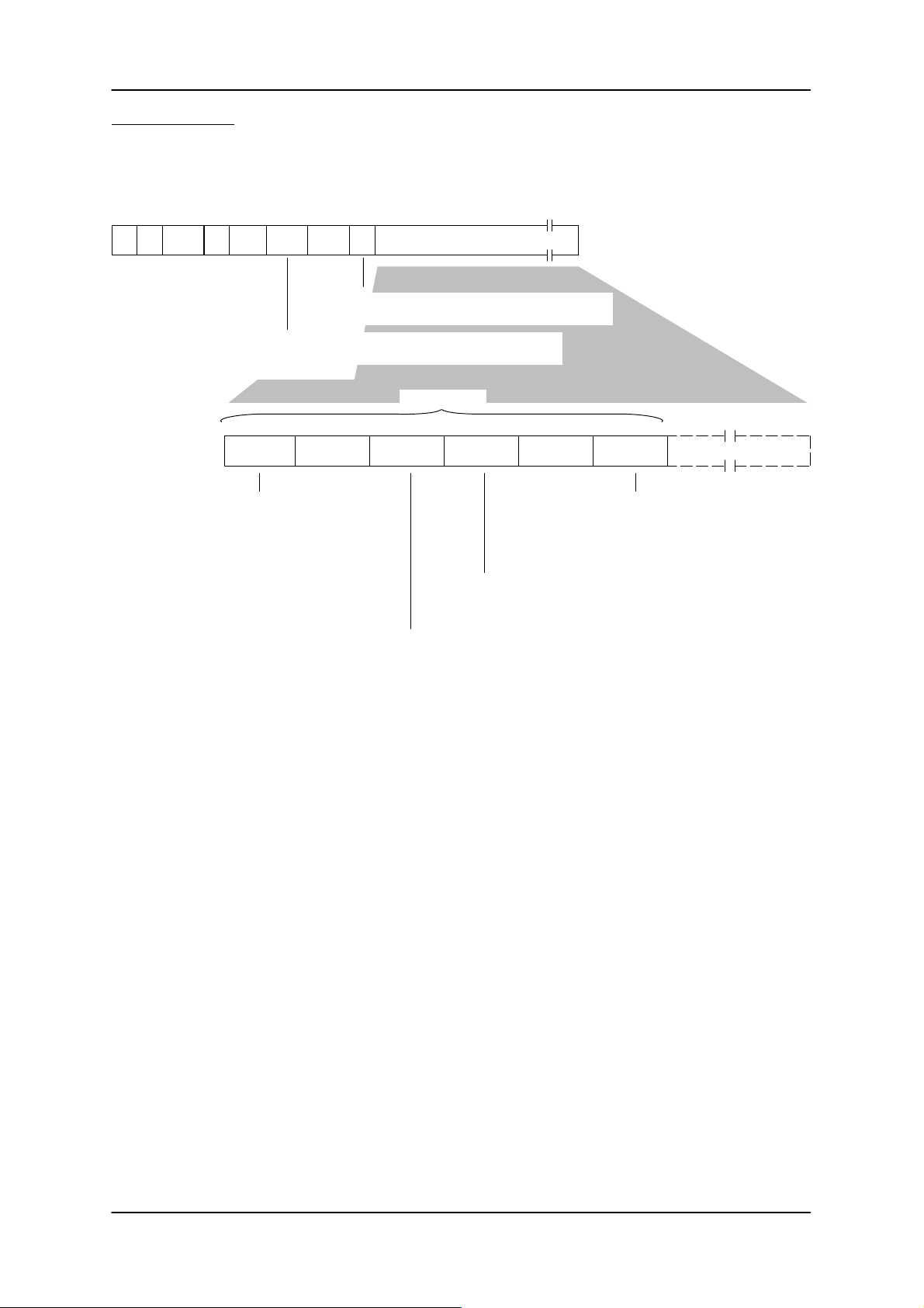
Acknowledgment:
ASM 421 Technical Description6GT2 097-3AH00-0DA2
0 1 2/3 4 5 6/7 8/9 10
KK Status ADB DBN DBL
00 xx 0000 xxxx
'E'
000100 xx xx xx xx xx xx xx xx xx xx
DBL
The total length of all data is calculated from the
sum of all DBLs in the acknowledgment telegrams.
The real number of subtelegrams for the QUEUEREAD
operation is supplied to the user here.
8 bytes 1 byte 3 bytes 2 bytes
File name Res. = 00 Length Skip (hex) Other file entries
The file name is identical to
the file name in the com
mand (with option 0008 the
unparameterized file
names appear here).
11/255
Data (max. of 244 bytes)
One file entry
File data Skip bytes
Optional: The skip bytes are only in
serted when skip has a value other
than 0000. The contents of the skip
byte are always blank" (20hex).
Number of data bytes after the data up to the beginning of
the next file name. Skip is always valid. With some options
skip always has the value 0000.
Length of the file data for this file. The data may cover
several subtelegrams.
Remarks:
The file entries with the file data can be placed anywhere in the data of the acknowledgment tele
gram. For example, part of the file name may be located in the first acknowledgment telegram.
The rest of the file name is then located in the next acknowledgment telegram.
Subject to change without notice!
RD: 03/02
J31069-D0142-U001-A0-7618
– 32 –
6GT2 002-0DA00 ASM 421 / V .24
6GT2 002-0DB00 ASM 421 / RS422
6GT2 002-0DC00 ASM 421 / TTY
Page 35
ASM 421 Technical Description 6GT2 097-3AH00-0DA2
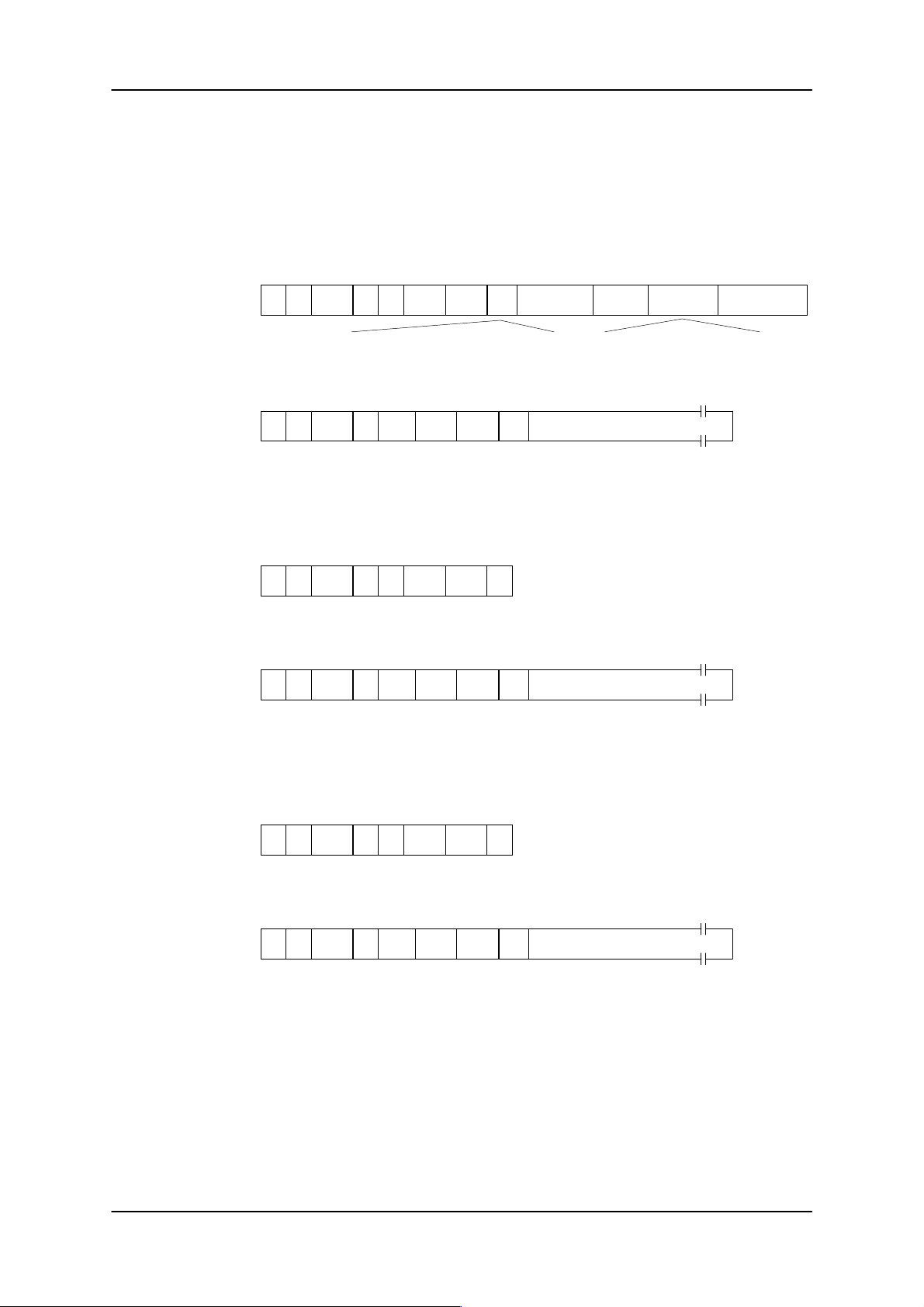
Example:
Five files are to be read from the MDS.
1st subtelegram on
filehandler:
Acknowledgment:
2nd subtelegram on
filehandler:
Acknowledgment:
0 1 2/3 4 5 6/7 8/9 10
KK KI ADB DBN DBL
xx 00 0000 0001
0 1 2/3 4 5 6/7 8/9 10
00 xx 0000 0003
0 1 2/3 4 5 6/7 8/9 10
xx 00 0000 0003
0 1 2/3 4 5 6/7 8/9 10
xx 00 0000 0003
'E'
= header + 5 file entries = 14 + 5 * 14 = 5 file entries = 5 * 14
KK Status ADB DBN DBL
'E'
KK KI ADB DBN DBL
'E'
KK Status ADB DBN DBL
'E'
0001 54H'I' 0000 000000 000046H
0001 F4H00
0002 00'I'
0002 F4H00
11/12 13/21 22/24
Option In reserve Length
11 to 254
Data (244 bytes)
File entries+ data
11 to 254
Data (244 bytes)
Con't: File entries + data
25 to 94
Data
File entries
3rd subtelegram on
filehandler:
Acknowledgment:
0 1 2/3 4 5 6/7 8/9 10
KK KI ADB DBN DBL
xx 00 0000 0003
0 1 2/3 4 5 6/7 8/9 10
00 xx 0000 0003
'E'
KK Status ADB DBN DBL
'E'
0003 00'I'
0003 0CH00
11 to 22
Data (12 bytes)
Con't: File entries + data
The total length of the data sent to the user can be calculated from the sum of all DBLs.
F4H + F4H + 0CH = 1F4H → Decimal: 500 bytes
The user data must be analyzed to obtain the data length of the individual files.
6GT2 002-0DA00 ASM 421 / V .24
6GT2 002-0DB00 ASM 421 / RS422
6GT2 002-0DC00 ASM 421 / TTY
– 33 –
Subject to change without notice!
RD: 03/02
J31069-D0142-U001-A0-7618
Page 36
ASM 421 Technical Description6GT2 097-3AH00-0DA2
3.4.7 DELETE
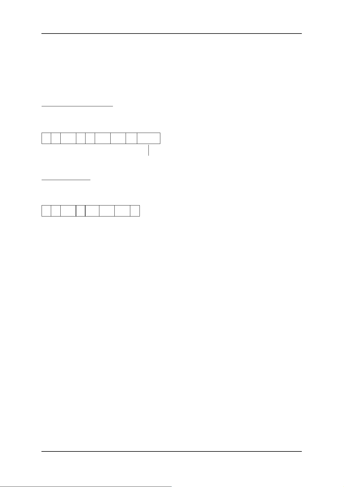
The file is removed from the MDS directory. The reserved memory area is released, and becomes available for other MDS operations. DELETE does not erase old user data.
A delete protected file cannot be deleted: it must have its delete protection attribute removed using the
ATTRIB command before it can be deleted.
Telegram to the file handler:
0 1 2/3 4 5 6/7 8/9 10
CC CI ADB DBN DBL
xx 00 0000 0001
’D’
0001 08H’I’
Acknowledgement:
0 1 2/3 4 5 6/7 8/9 10
CC Status ADB DBN DBL
00 xx 0000 0001
’D’
0001 0000
11/18
F.name
Name of file to be deleted; 8 ASCII characters (20H-7EH)
Subject to change without notice!
RD: 03/02
J31069-D0142-U001-A0-7618
– 34 –
6GT2 002-0DA00 ASM 421 / V .24
6GT2 002-0DB00 ASM 421 / RS422
6GT2 002-0DC00 ASM 421 / TTY
Page 37

ASM 421 Technical Description 6GT2 097-3AH00-0DA2
3.4.8 COVER
1. The file structure of an MDS can be protected against unauthorized access. This means that commands which cause changes in a checksum or create additional DIR or FAT entries can only be issued
by authorized users (superusers).
An unauthorized access includes the following:
– Files are deleted or set up.
– File lengths are shortened or lengthened.
– Data carriers are formatted although they have been formatted already.
– Attributes are deleted or new ones are assigned.
After generating the valid file structure on the MDS, an authorized user (superuser) must protect this
with the COVER command. This prevents other users from destroying checksums by accessing the
data carrier. An illegal command is rejected with error message D022.
2. If the superuser wants to format the MDS or delete/set up files, he/she must first “open” the data carrier
again with the COVER command.
3. A COVER command for an unformatted MDS is rejected with error D015.
4. Specification of a volume name (i.e., MDS name) with the COVER command ensures that a data carrier must be unmistakably identified by the superuser. The COVER command is rejected with error
D023 when the two MDS names (i.e., data carrier name and volume name in the COVER command)
are not identical. Specification of a user identifier (byte 19 in the command telegram) greater than
01 hex is rejected with error message D005.
Telegram to the file handler:
0 1 2/3 4 5 6/7 8/9 10 11/18 19
CC CI ADB DBN DBL
xx 00 0000 Volume User
’C’
’I’ 0001 090001
01H: The MDS is to be protected against unauthorized access.
00H: Changes to the MDS file structure are permitted again.
Acknowledgement:
0 1 2/3 4 5 6/7 8/9 10
CC Status ADB DBN DBL
00 xx 0000 ADB
’C’
0001 0000
6GT2 002-0DA00 ASM 421 / V .24
6GT2 002-0DB00 ASM 421 / RS422
6GT2 002-0DC00 ASM 421 / TTY
– 35 –
Subject to change without notice!
RD: 03/02
J31069-D0142-U001-A0-7618
Page 38
3.4.9 DIR
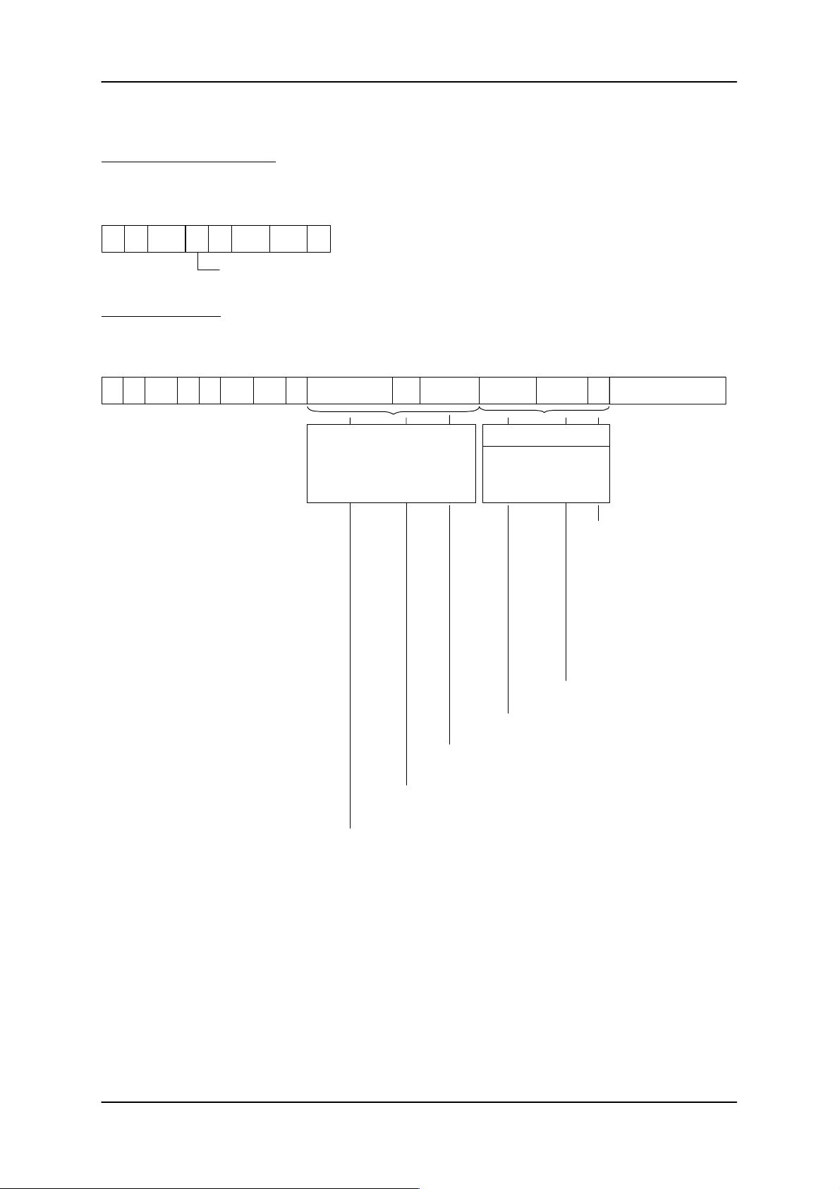
Telegram to the file handler:
0 1 2/3 4 5 6/7 8/9 10
CC CI ADB DBN DBL
xx 00 0000 0001
’G’
0001 00’I’
Get Dir
Acknowledgement:
ASM 421 Technical Description6GT2 097-3AH00-0DA2
0 1 2/3 4 5 6/7 8/9 10 11/18 19/20 21/24 25/32
Sta–
CC
00 xx 0000 0001 xx ’MDs NAME’ 00000015 00000A
’G’
ADB DBN DBL
tus
00 0001
xxxx ’ FILE1’ 00 Further file entries
File entry
MDS related data
A data record with the
form as shown is
transmitted to the user
Length of file in bytes
(10 bytes in this case)
File name; 8 ASCII characters
3633/35
Attribute for this file
(no attribute in this case)
00 = no attribute
01 = read only
02 = write once; over-
writing not possible
04 = Fixed length.
The length cannot be
changed with write
commands.
05 = Same as 04. The file
may only be read.
Free memory space in MDS in bytes
(4 bytes, hex)
Check sum calculated by file handler via DIR and F AT. The check sum
is placed in the system area on the MDS.
Name of MDS; 8 ASCII characters
If the MDS directory contains a large number of files, the directory data will be transmitted as blocks
(ADB > 1 in the first acknowledgement). The user must request the additional blocks.
Subject to change without notice!
RD: 03/02
J31069-D0142-U001-A0-7618
– 36 –
6GT2 002-0DA00 ASM 421 / V .24
6GT2 002-0DB00 ASM 421 / RS422
6GT2 002-0DC00 ASM 421 / TTY
Page 39
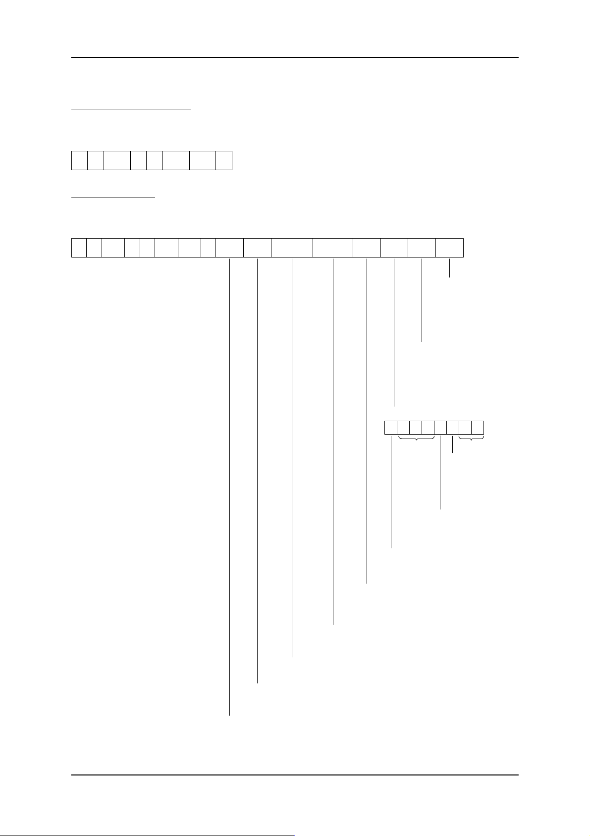
ASM 421 Technical Description 6GT2 097-3AH00-0DA2
3.4.10 MDS STATUS
Telegram to the file handler
0 1 2/3 4 5 6/7 8/9 10
CC CI ADB DBN DBL
xx 00 0000 0001
’F’
0001 00’I’
Acknowledgement:
0 1 2/3 4 5 6/7 8/9 10 11/18 20/22 23/25 26/27
Sta-
CC
00 xx 0000 0001 16 Vol.
ADB DBN DBL
tus
’F’
00 0001
19 32
Type
Tot.cap.
MDS capacity:
Max. size of the user data area in the MDS in bytes (24 bits/hex)
Free cap. DIR Ind. BZ ECC
Free DIR entries:
Current count of free directory entries. This
number of further files can be opened.
(16 bits/hex).
Current free capacity:
Free or not yet reserved memory capacity on the MDS
(24 bits/hex)
28 29/31
ECC corrections:
counts number of ECC
corrections performed:
only valid when working
with ECC
No. of times processed:
this counter has a width of 24
bits. It is incremented by 1 at
each SLG station before being
processed for the first time.
Indication (binary):
7 6 5 4 3 2 1 0
res.res.
Support battery
0=OK
1 = poor
This bit is always set
for MDS types with
EEPROM
Aux. battery
(only for MDS 507 )
0=OK
1 = poor
0 = MDS is not protected.
1 = MDS is protected (by COVER
command).
6GT2 002-0DA00 ASM 421 / V .24
6GT2 002-0DB00 ASM 421 / RS422
6GT2 002-0DC00 ASM 421 / TTY
MDS type:
The MDS was formatted with this MDS type by the FORMAT command (see section 3.4.1) (1 byte/hex)
Volume:
Name of MDS; 8 ASCII characters (20H-7EH); the name was assigned during FORMAT.
– 37 –
Subject to change without notice!
RD: 03/02
J31069-D0142-U001-A0-7618
Page 40
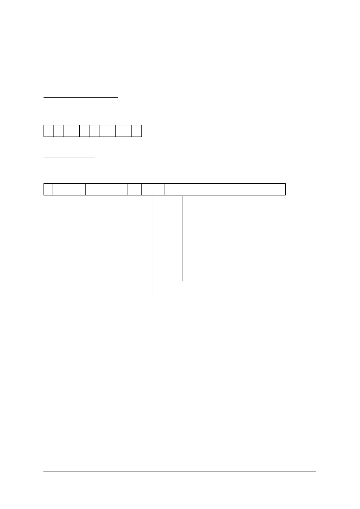
ASM 421 Technical Description6GT2 097-3AH00-0DA2
3.4.11 ASM STATUS
The ASM STATUS command provides information from the file handler. The command can be used to
look for errors. It shows the telegram traffic performed by the ASM 421.
Telegram to the file handler:
0 1 2/3 4 5 6/7 8/9 10
CC CI ADB DBN DBL
xx 00 0000 0001
’S’
0001 00’I’
Acknowledgement:
0 1 2/3 4 5 6/7 8/9 10 11/18 19/44 71
CC Status ADB DBN DBL
00 xx 0000 0001 Vers. no. Last instruction Connection status
* Only the data are valid that pertain to the telegram header.
The data in the telegram can have any content.
’S’
00 0001 3DH Last ack.
26 bytes: byte 0 to byte 25 of the last command to the ASM *
Version ident. of the file handler; 8 bytes ASCII
45/70
Status information regarding state
of SLG hardware (24 V supply
present; fuse OK; cable to SLG OK;
SLG OK)
00H → Connection t o SLG is OK
01H → Fault in connection to
SLG
26 bytes: byte 0 t o byte 25 of the acknowledge-
ment of the last command *
Subject to change without notice!
RD: 03/02
J31069-D0142-U001-A0-7618
– 38 –
6GT2 002-0DA00 ASM 421 / V .24
6GT2 002-0DB00 ASM 421 / RS422
6GT2 002-0DC00 ASM 421 / TTY
Page 41
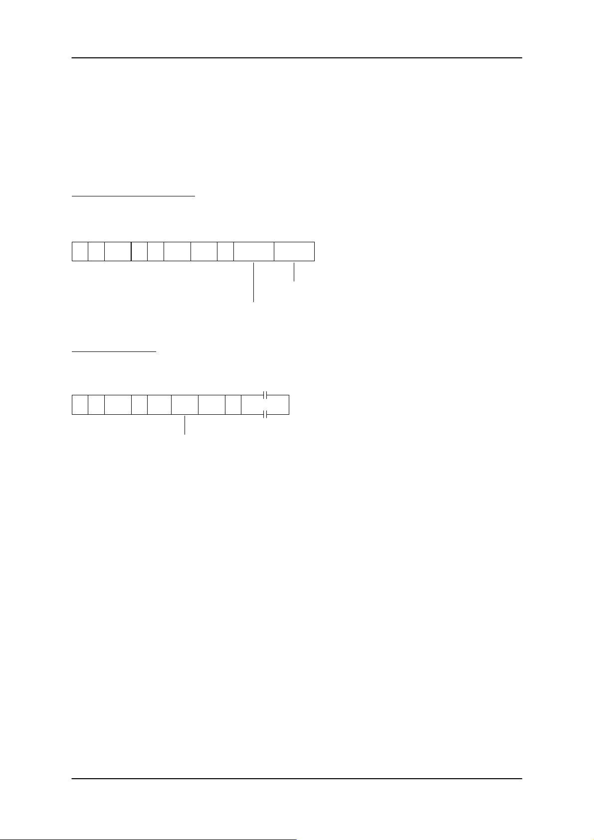
ASM 421 Technical Description 6GT2 097-3AH00-0DA2
3.4.12 TRACE
The TRACE command provides a physical dump of the MDS memory. It can be very useful for test purposes. The selected type of entry / exit checking is irrelevant as far as this command is concerned. It is
always executed immediately.
If a data block that exceeds the maximum telegram length is to be read, the data will be transmitted in
blocks. Refer to the example in section 3.4.5 to see how the blocking function works.
Telegram to the file handler:
0 1 2/3 4 5 6/7 8/9 10
CC CI ADB DBN DBL
xx 00 0000 0001
’T’
0001 06’I’
11/13
Start addr.
xxxxxxH
Physical start address in the MDS of the data to be
read (3 bytes hex)
14/16
Length
xxxxxxH
Length of the data to be read (3 bytes hex)
Acknowledgement:
0 1 2/3 4 5 6/7 8/9 10
CC Status ADB DBN DBL
00 xx 0000 0001
’T’
0001 xx00
If data length > telegram length:
the file handler calculates ADB and sends the value to the user in the first
acknowledgement telegram
11/254
Data
Data
The TRACE command is the only file handler command that does not return an error indicator in the
acknowledgement when processing an MDS that is not formatted (but is initialized). In each case the
acknowledgement contains the physical MDS addresses.
The ECC mode should be set correctly with the RESET command before using the TRACE command.
6GT2 002-0DA00 ASM 421 / V .24
6GT2 002-0DB00 ASM 421 / RS422
6GT2 002-0DC00 ASM 421 / TTY
– 39 –
Subject to change without notice!
RD: 03/02
J31069-D0142-U001-A0-7618
Page 42
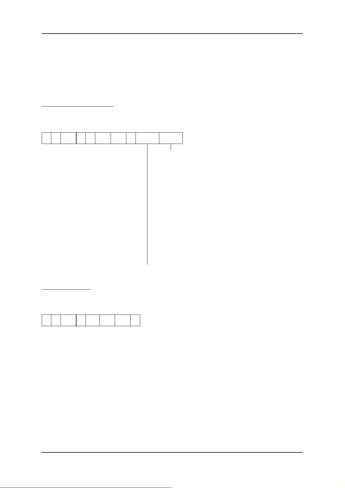
ASM 421 Technical Description6GT2 097-3AH00-0DA2
3.4.13 ATTRIB
The ATTRIB command enables access rights to be assigned to individual files. T ogether with the access
rights that can be set for each ASM with the DIL switches, each user can individually set the desired access rights. The access rights from the DIL switch and ATTRIB command should be ‘ORed’ together, i.e.
both access rights must be correct in order to carry out the command.
Telegram to the file handler:
0 1 2/3 4 5 6/7 8/9 10
CC CI ADB DBN DBL
xx 00 0000 0001
’Y’
0001 09’I’ F.name
11/18 19
Attribute
Assigning or changing access rights for this file
00H: no attribute for the data entered or delete existing attribute
01H: attribute “read only”
The file can only be read (no DELETE or WRITE or
UPDATE permissible).
02H: attribute “write once”
The file can be written once and then only read
(DELETE or WRITE or UPDATE not permitted).
04H: attribute “fixed length”
The length of the file cannot be changed by write
commands such as UPDATE, WRITE or APPEND
(i.e., the checksum in the system area is not changed
by a write access to this file.
05H: Same as 01H
When other access rights are specified in the ATTRIB
command, this is rejected with error message D005.
File name; 8 ASCII characters (20H-7EH)
Acknowledgement:
0 1 2/3 4 5 6/7 8/9 10
CC Status ADB DBN DBL
00 xx 0000 0001
’Y’
0001 0000
Example:
DIL Switch: DELETE (all commands allowed)
Attribute of file “EXAMPLE”: 02H (write once)
The file “EXAMPLE” can be read and can be written once. Deletion of the file is not possible. However, the
MDS can be completely erased with the FORMAT command.
Subject to change without notice!
RD: 03/02
J31069-D0142-U001-A0-7618
– 40 –
6GT2 002-0DA00 ASM 421 / V .24
6GT2 002-0DB00 ASM 421 / RS422
6GT2 002-0DC00 ASM 421 / TTY
Page 43

ASM 421 Technical Description 6GT2 097-3AH00-0DA2
3.4.14 NEXT
The NEXT command terminates the processing of an MDS. The command after the NEXT command will
only be processed if a new MDS enters the transmission window of the SLG.
Telegram to the file handler:
0 1 2/3 4 5 6/7 8/9 10
CC CI ADB DBN DBL
xx 00 0000 0001
’N’
0001 00’I’
Acknowledgement:
0 1 2/3 4 5 6/7 8/9 10
CC Status ADB DBN DBL
00 xx 0000 0001
’N’
0001 0000
It is essential to program the NEXT command for the following types of entry / exit checking (EAKO):
– MDS recognition by field scanning: EAKO = 0 (see section 5.1)
– MDS control via 1 DI: EAKO = 2 and field scanning (see section 5.3)
– MDS control via 2 DI: EAKO = 3 (see section 5.4)
The NEXT command does not need to be programmed for the operating modes “timeout” and “without
entry / exit checking”. Should it nevertheless be programmed, it will be processed in all its aspects by the
file handler.
Further information about this command can be found in section 5.
6GT2 002-0DA00 ASM 421 / V .24
6GT2 002-0DB00 ASM 421 / RS422
6GT2 002-0DC00 ASM 421 / TTY
– 41 –
Subject to change without notice!
RD: 03/02
J31069-D0142-U001-A0-7618
Page 44
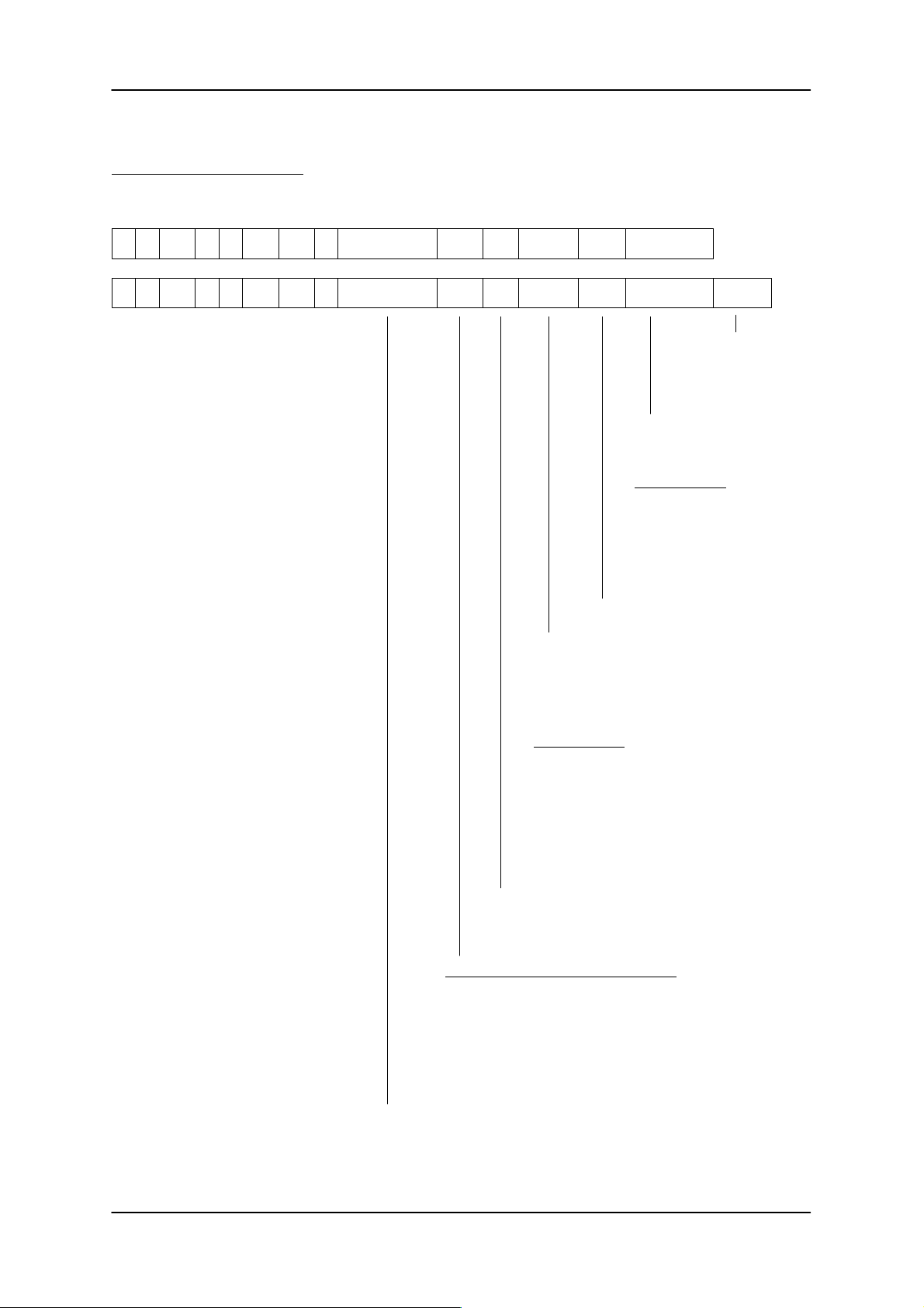
3.4.15 RESET
Telegram to the file handler:
ASM 421 Technical Description6GT2 097-3AH00-0DA2
0 1 2/3 4 5 6/7 8/9 10 11 12 16
14/15
13 17
CC CI ADB DBN DBL
00xx 0000 0001 RESET mode EAKO SLG No.
’X’
’I’ 0001 07 ECC
Prior. Block length
’X’00xx 0000 0001 RESET mode EAKO SLG No.’I’ 0001 07 ECC Prior. Block lengthOrt
at present always ’0’
SLG number of this ASM/SLG station:
the value entered here will be placed in the system
area of the MDS before command processing begins. It forms an important feature of the entry/exit
checking. If an MDS moves outside the field and
comes back, the file handler knows that it is the old
MDS that has just been processed.
Range of values:
0000 = reserved
0001 ... FFFE = normal SLG no.
FFFF = Test function:
ABTAST
Scanning interval for
presence check (for
operation of MDS
507/407E,
see page 43)
Max. telegram length;
the file handler will not send an
acknowledgement telegram that
exceeds the length given here.
Range of values:
64 ... 254
0 = Sets the default value of
128 bytes
If the data length exceeds the
max. block length, the data will be
transmitted in block form (see
section 3.3)
Important:
Each SLG in a system must
have a different SLG number.
The next MDS can be the same
one despite the NEXT command.
Subject to change without notice!
RD: 03/02
J31069-D0142-U001-A0-7618
’0’ = ECC disabled (default)
’1’ = ECC mode
A description and function of ECC (error correction code)
can be found in the FB 250 description.
Type of entry/exit checking (1 byte, ASCII)
’0’ = MDS recognition by field scanning; NEXT command is man-
datory (see section 5.1)
’1’ = Without entry/exit control; timeout on ASM 421
(see section 5.2)
’2’ = MDS control via 1 DI and field scanning (see section 5.3)
’3’ = MDS control via 2 DIs (see section 5.4)
’4’ = Without entry/exit control (see section 5.5)
’5’ = Special operating mode: If the check sum changes, system
area may only be written, no NEXT (see section 5.6)
’B’ = Break (hard reset); all MDS actions are immediately aborted. Data in the
MDS may possibly no longer be consistent
’C’ = Close (soft reset); The command currently being processed will be termi-
nated and the directory updated. The data in the MDS are guaranteed to be
consistent. The acknowledgement of the soft reset may be delayed.
– 42 –
6GT2 002-0DA00 ASM 421 / V .24
6GT2 002-0DB00 ASM 421 / RS422
6GT2 002-0DC00 ASM 421 / TTY
Page 45
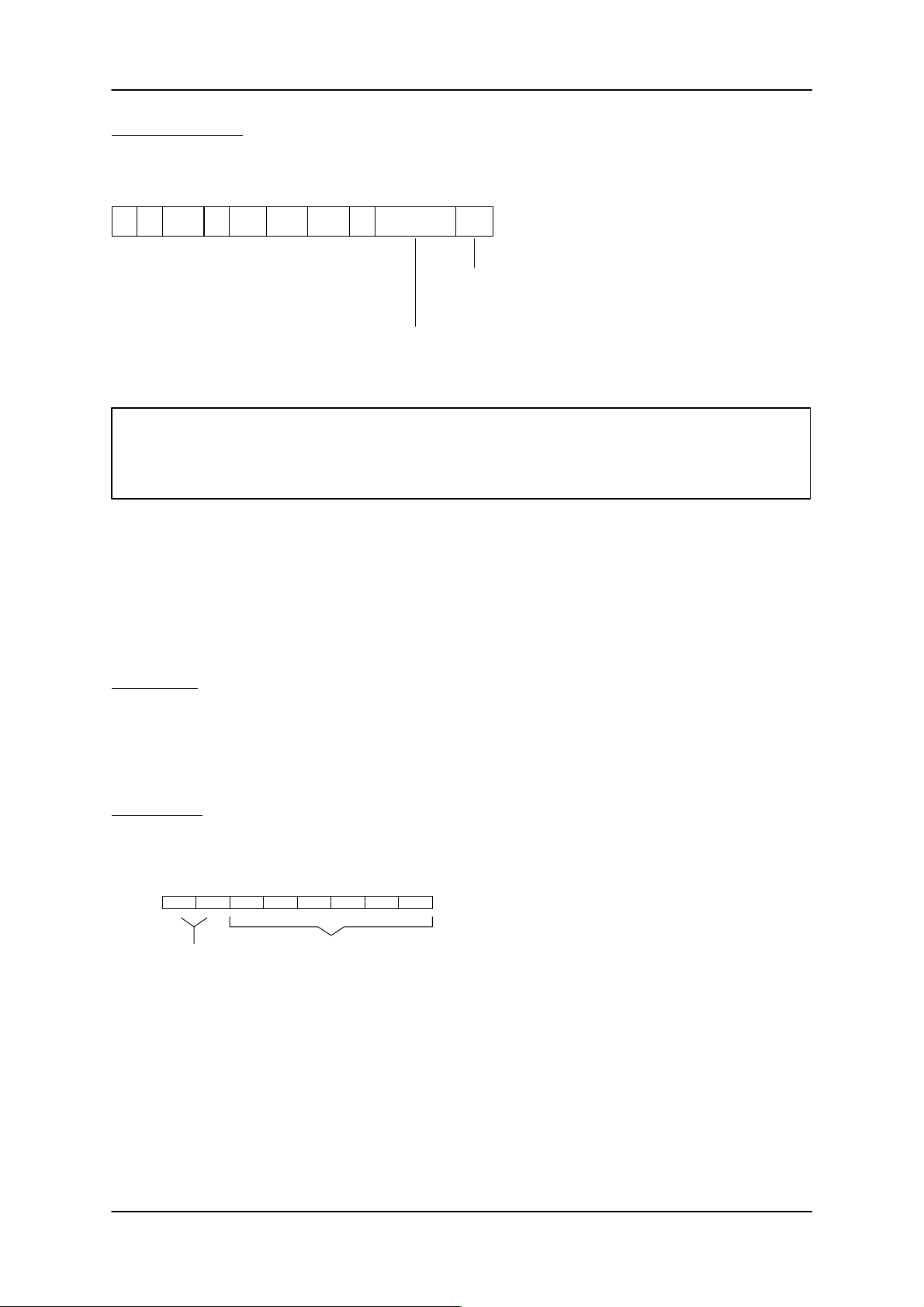
ASM 421 Technical Description 6GT2 097-3AH00-0DA2
Acknowledgement:
0 1 2/3 4 5 6/7 8/9 10
CC Status ADB DBN DBL
00 xx 0000 0001
’X’
0001 0500
11/14 15
Error code ANW
Proximity status (1 byte ASCII)
’0’ = no MDS in the SLG field
’1’ = MDS in SLG field
The error code is normally 0000. These 4 characters only contain
information if the status byte (byte 5) shows an error.
Important:
The ASM 421 must receive a RESET telegram from the user whenever power is restored. Any other
type of telegram will be rejected with an error.
A RESET command sets the parameters for the file handler on the ASM 421 , which starts to function (the
single blinking of the red LED ceases and the yellow LED must come on, if the connection to the SLG is
OK). The RESET command is required when a command or a sequence of telegram blocks is to be
aborted.
If a command is terminated by the file handler with an error, no RESET command is necessary.
Please note:
A RESET command declares the current MDS directory on the ASM to be invalid. For the next MDS to be
processed, the directory must in each case first be read from the MDS. To avoid the time delay inherent in
reading the directory, the MDS directory can be loaded by the user into the ASM with the LOAD command
immediately after the RESET command (see section 3.4.16).
Definition of t
t
ABTAST
is parameterized as a hex value.
ABTAST
:
Bit: 7 6543210
Time value: 00-3F
Time factor:
00 = 0.01 sec
01 = 0.1 sec
10 = 1 sec
11 = 10 sec
For detailed explanation of t
, see the configuration manual for SLG 44/MDS 507/MDS 407E.
ABTAST
6GT2 002-0DA00 ASM 421 / V .24
6GT2 002-0DB00 ASM 421 / RS422
6GT2 002-0DC00 ASM 421 / TTY
– 43 –
Subject to change without notice!
RD: 03/02
J31069-D0142-U001-A0-7618
Page 46
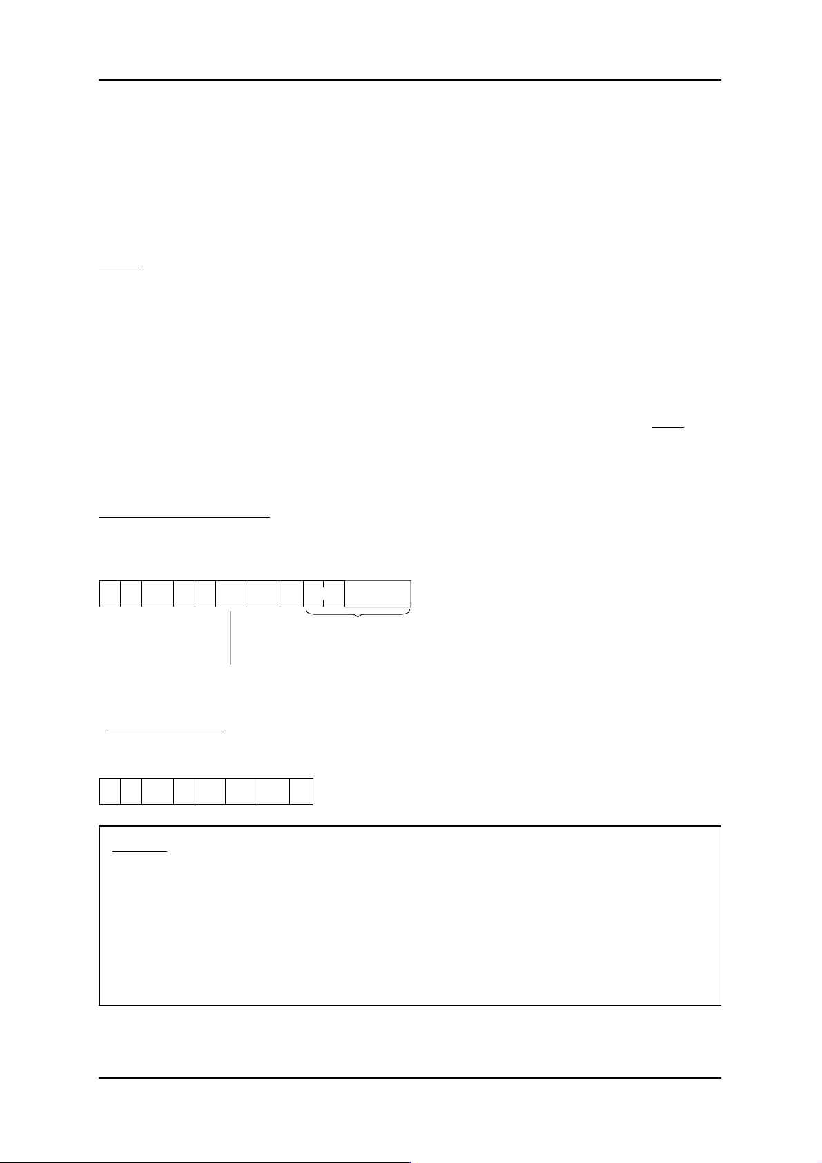
ASM 421 Technical Description6GT2 097-3AH00-0DA2
3.4.16 LOAD/MOVE
The LOAD and MOVE commands are optional file handler commands. These allow access times to MDS
data following a cold start or restart to be optimized. The time spent reading a directory is eliminated for the
first MDS to enter the field. The LOAD/MOVE commands are only meaningful if the same directory is
present in all data carriers in the system.
LOAD:
A protected directory is transmitted from the user to the ASM. This command can be issued by the user
after the RESET, to load the old directory into the ASM. When the first MDS to arrive is processed, the
directory does not then need to be read in from the MDS. The time for the directory to be read does not
need to be considered when designing the system. Especially important in dynamic operation: the first
MDS to arrive after a RESET can immediately be processed at full transport speed.
The file handler checks the directory transmitted by the ‘L’ command for plausibility. Check sums and directory data must correspond. If this is not the case, the user receives the error message D007 in the
acknowledgement. The file handler continues to function normally despite this error message. The directory transmitted by the ‘L’ command will be rejected. The file handler reads the directory from the first MDS
to arrive.
Telegram to the file handler:
0 1 2/3 4 5 6/7 8/9 10 11/12 13 ...
CC CI ADB DBN DBL
00xx 0000 ADB DBL Length
’L’
’I’ 0001 DIR + F AT
Data protected in user control by the MOVE command
The data block count is calculated from the length of the data
(bytes 11/12). It must be calculated correctly by the user (see
example in section 3.4.4).
Data
Acknowledgement:
0 1 2/3 4 5 6/7 8/9 10
CC Status ADB DBN DBL
00 xx 0000 ADB 00
’L’
00 0001
Warning: A RESET command deletes the directory stored in the ASM, i.e. the complete
directory will be read from the next MDS following a RESET command.
An error message from any command can delete the directory stored in the ASM
as well (see chapter 7).
Subject to change without notice!
RD: 03/02
J31069-D0142-U001-A0-7618
In applications using the LOAD/MOVE commands, a LOAD command must
therefore be programmed after each RESET command and after each error
message.
– 44 –
6GT2 002-0DA00 ASM 421 / V .24
6GT2 002-0DB00 ASM 421 / RS422
6GT2 002-0DC00 ASM 421 / TTY
Page 47
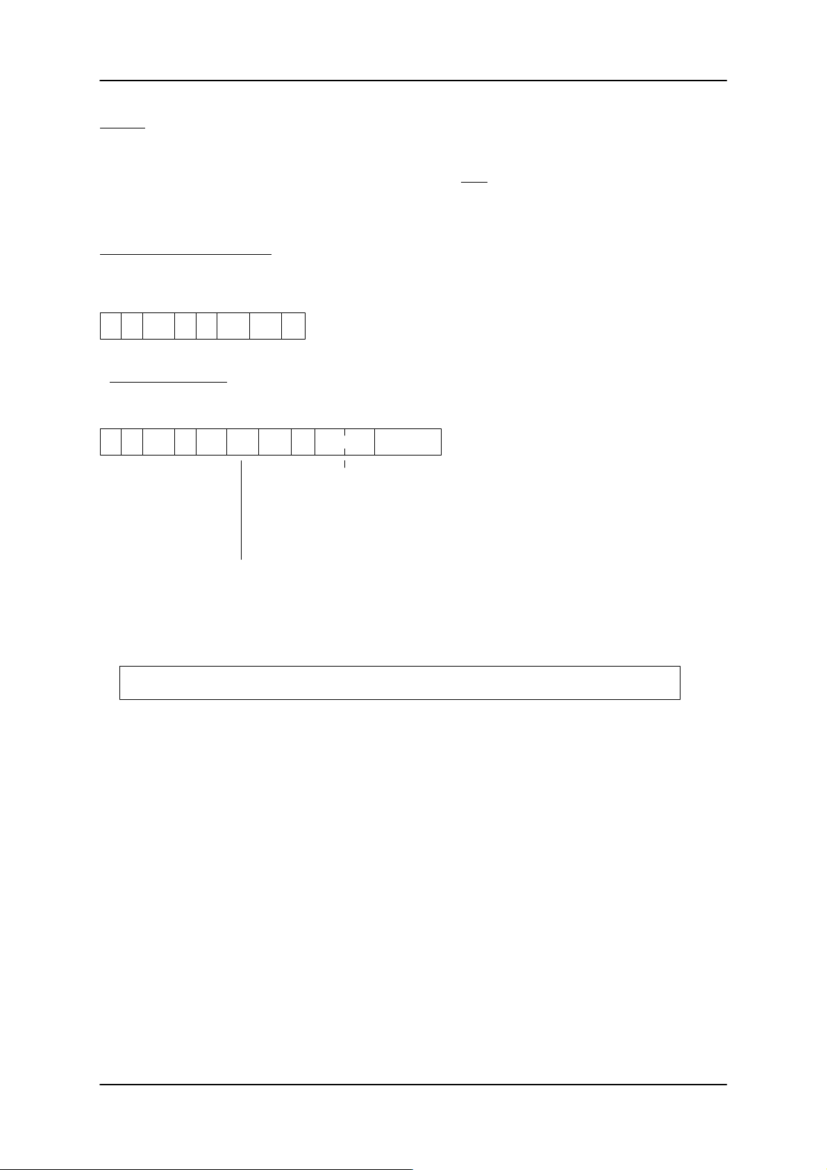
ASM 421 Technical Description 6GT2 097-3AH00-0DA2
MOVE:
The MOVE command provides the user with the data in the directory that has just been stored in the ASM
(DIR + FAT + checksum). It can be issued by the user after bit 6 is set in the status byte of the acknowledgement of any command. For a more rapid cold start and restart, the user can store the data of the ‘M’
command in non-volatile memory (battery buffered or magnetic media).
Telegram to the file handler:
0 1 2/3 4 5 6/7 8/9 10
CC CI ADB DBN DBL
00xx 0000 0001 00
’M’
’I’ 0001
Acknowledgement:
0 1 2/3 4 5 6/7 8/9 10
CC Status ADB DBN DBL
00 xx 0000 xxxx DBL
* Calculation of the actual amount of data to be moved by the MOVE command (see also table in Chapter 1):
’M’
00 0001
The actual number of telegram segments is passed to the
user here.
11/12 13 ...
Data
Length* DIR + FAT
The length of the DIR + FAT data can vary. It will be at its maximum when the maximum
number of files has been created and the whole MDS is full of data.
Length = (DIR + FAT) + 2 bytes
(Byte 11 + 12 of the telegram are already counted in the length)
Max. length. = [(No. of blocks * 2) + (max. no. of files * 14) + 9] bytes
6GT2 002-0DA00 ASM 421 / V .24
6GT2 002-0DB00 ASM 421 / RS422
6GT2 002-0DC00 ASM 421 / TTY
– 45 –
Subject to change without notice!
RD: 03/02
J31069-D0142-U001-A0-7618
Page 48
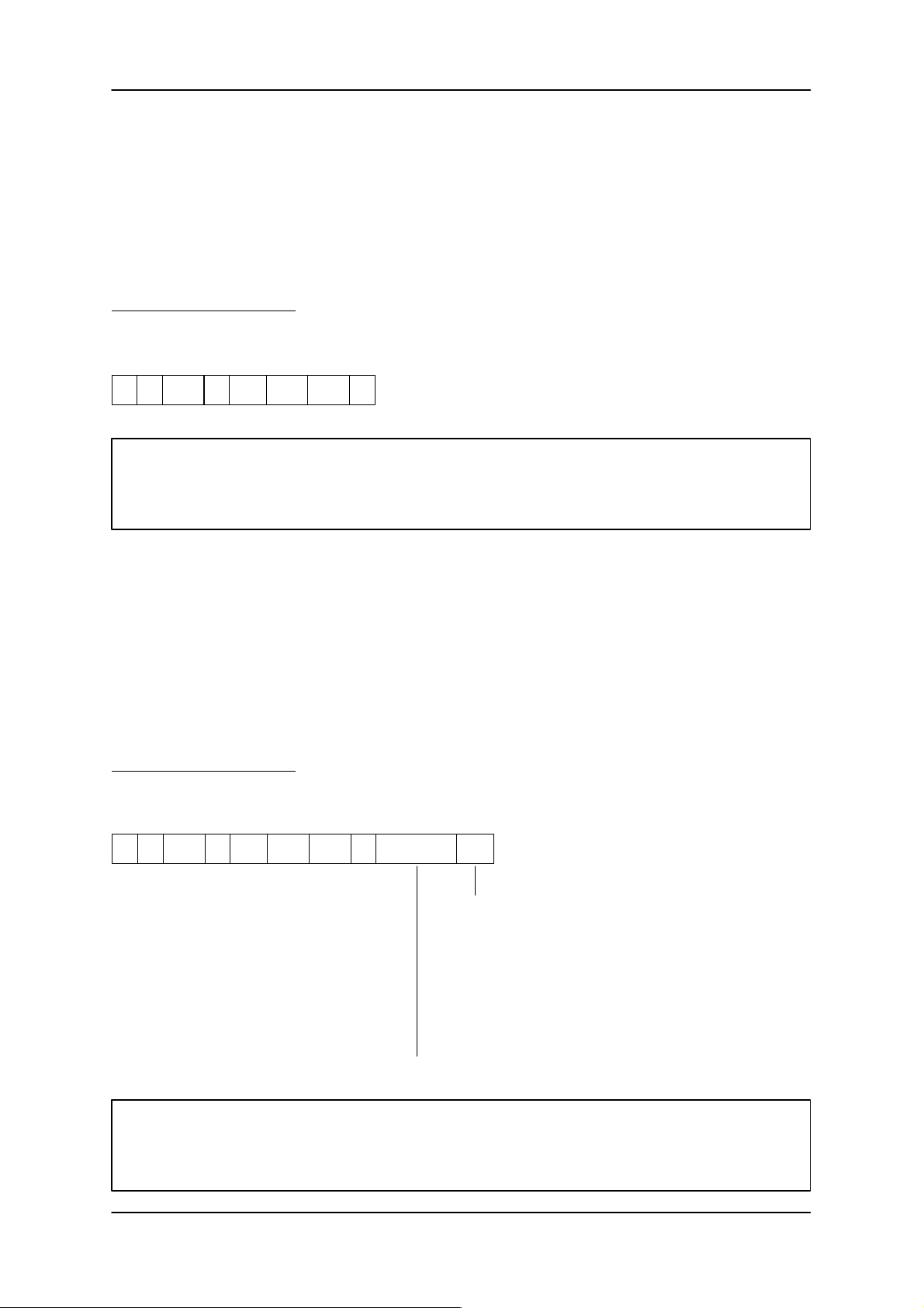
ASM 421 Technical Description6GT2 097-3AH00-0DA2
3.5 Telegrams from file handler
In normal operation the user receives only one telegram (acknowledgement) if a command has previously
been sent to the ASM. In two cases however , the ASM becomes active and sends a telegram to the user
asynchronously:
– Start-up message
– Proximity change
3.5.1 Start-up message
Telegram from file handler:
0 1 2/3 4 5 6/7 8/9 10
CC Status ADB DBN DBL
00 00 0000 0001
’H’
0001 0000
(see Chapter 4)
Note:
After sending a start-up message, the file handler firmware will only accept a RESET telegram.
All other commands will be rejected with an error!
The file handler sends the start-up message whenever power is restored. If the user is not ready to receive, a number of repeats will be carried out within the framework of the 3964R procedure
(see section 3.1).
If the user receives a start-up message during operation, the 24 V supply has failed for a short period. A
previously programmed command will no longer be processed by the file handler.
3.5.2 Change in proximity status
A change in proximity status (Z message) will only be signalled by the file handler if this has been specified
by setting the DIL switch on the module (see section 2.3).
Telegram from file handler:
0 1 2/3 4 5 6/7 8/9 10
CC Status ADB DBN DBL
00 00 0000 0001
’Z’
0001 0500
11/12/13/14 15
Error code ANW
Proximity status of an MDS:
’0’ = No MDS present; the MDS has just moved out of the
transmission window
’1’ = MDS present; an MDS has moved into the transmission
window of the SLG. (green LED on ASM is lit)
EXCEPTION: If the “connection to SLG” has been broken
since proximity (ANW) is reported in this
way. As a result when the user sends his
command to the ASM, he receives the
corresponding error message in the
acknowledgement).
No error code is given for a proximity message (ASCII: ’0000’)
Important:
The proximity change message comes fully asynchronously from the ASM. The user must always
be ready and able to accomodate this message.
Subject to change without notice!
RD: 03/02
J31069-D0142-U001-A0-7618
– 46 –
6GT2 002-0DA00 ASM 421 / V .24
6GT2 002-0DB00 ASM 421 / RS422
6GT2 002-0DC00 ASM 421 / TTY
Page 49
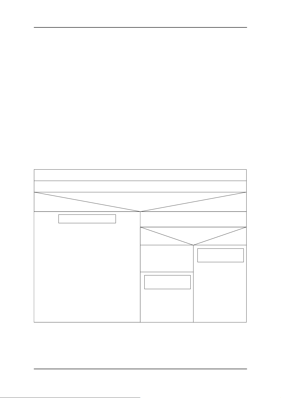
ASM 421 Technical Description 6GT2 097-3AH00-0DA2
4 Cold start and restart
Cold start and restart must be performed by the user and the ASM 421 in a coordinated manner. Only then
can ASM and user operations be synchronized properly.
Cold start and restart on the ASM 421 side:
After switc h i n g o n t h e power supply, the ASM 421 performs a comprehensive self-test. This takes about 2
seconds. During this time the ASM cannot communicate with the user. The ASM will not respond to any
telegram from the user (also no NAK at the procedure level).
After the self-test, the ASM sends a start-up message (see section 3.5.1) and is immediately ready to
receive.
If the start-up message is not acknowledged by the user (e.g. user is not ready or switched off) the message will be lost. As a result the red LED flashes 28 times.
The ASM now always expects to receive a RESET telegram containing the relevant parameters from the
user (see section 3.4.15). Any other telegram will not be processed and will be rejected with an error.
Following the RESET, the ASM is able to process all the commands described in section 3.4.
Cold start and restart on the user (computer) side:
The following structogram shows a secure synchronization procedure for restarting the user program:
Computer or PC sw it ched on
Send RESET telegram to ASM 421
Telegram acknowledged correctly ?
Yes No
ASM is synchronized
– ASM was not switched off
– ASM has performed its self-test more quickly than
the computer; the start-up telegram from the ASM is
lost
Wait max. 3 seconds for start-up telegram from the ASM
Start-up telegram re-
Yes No
Send RESET telegram
to ASM and fetch acknowledgement
ASM is synchro-
nized
ceived ?
ASM is not syn-
chronized
– ASM is switched off
or defective
– Message sent to
user
– Start synchroniza-
tion procedure with
ASM cyclically
6GT2 002-0DA00 ASM 421 / V .24
6GT2 002-0DB00 ASM 421 / RS422
6GT2 002-0DC00 ASM 421 / TTY
– 47 –
Subject to change without notice!
RD: 03/02
J31069-D0142-U001-A0-7618
Page 50

ASM 421 Technical Description6GT2 097-3AH00-0DA2
General evaluation of a start-up telegram by the computer:
The start-up telegram can be sent from the ASM to the user at any time (e.g. following a short power failure). To ensure stable operation, the user must always be in a position to accept and evaluate the incoming telegram.
Telegram received from ASM
Start-up message ?
Yes No
– Send RESET telegram to ASM and fetch acknow-
ledgement
Was command active on
Yes No
– Command is
aborted
– Fault message to
user
– Reissue com-
mand to ASM
the ASM ?
Ready to receive next telegram
– Correct acknowledgement; evaluation of telegram
– Proximity message (Z telegram)
Subject to change without notice!
RD: 03/02
J31069-D0142-U001-A0-7618
– 48 –
6GT2 002-0DA00 ASM 421 / V .24
6GT2 002-0DB00 ASM 421 / RS422
6GT2 002-0DC00 ASM 421 / TTY
Page 51

ASM 421 Technical Description 6GT2 097-3AH00-0DA2
5 Checking entry and exit of MDS in SLG transmission window
This chapter describes various procedures for recognizing when an MDS is within range of an SLG. The
user can use the procedure most appropriate for the application with the RESET command: EAKO (see
section 3.4.15).
The following table shows the various types of entry/exit checking:
EAKO MDS entry MDS exit Command executed NEXT
“0” Field scanning Field scanning If MDS present Yes Yes No
“1” User User Immediate; error if no
“2” DI0 on ASM Field scanning If MDS is present via
“3” DI0 on ASM DI1 on ASM If MDS present Yes Yes Yes
“4” User User If MDS detected by field
“5” User User No No No
MDS in field
DI0; error if field
scanning does not
detect MDS
scanning
If MDS detected by field
scanning
command
necessary?
No No Yes
Yes Yes Yes
No No No
Continuous
MDS flow
control by file
handler
Has filehandler
recognized
defective MDS?
General procedure for an SLG:
For each SLG that is to process an MDS, the station-specific SLG number is written to the system
area of the MDS. The SLG number is written automatically before the first command to be executed on
the MDS. The file handler recognizes from the SLG number whether a new or an old data carrier is currently present in the transmission window of the SLG.
New MDS: SLG numbers (SLG no. on MDS and station-specific SLG no.) do not correspond
Old MDS: SLG numbers correspond
Current MDS: All active commands apply to this MDS
Next MDS bit: Internal status flag in the file handler
ANW bit: Presence bit; the status of this bit is indicated by the green LED and on the backplane
connector (z18). As an option, the user can receive an ANW message if the ANW bit
changes (Z message: switch-selectable parameter).
The old MDS remains current (all commands relate to this MDS) until it is closed by a NEXT command. All
subsequent commands refer on this SLG to the next new MDS. This is achieved by having the file handler
set the “next MDS bit” when it receives a NEXT command. If the old MDS reenters the SLG transmission
window as the next MDS (SLG numbers correspond), no command is issued (the “next MDS bit” remains
set). When a new MDS enters the transmission window, the “next MDS bit” will be reset and the
station-specific SLG number will be written to the system area of the MDS (the new MDS thus becomes
the old/current MDS).
6GT2 002-0DA00 ASM 421 / V .24
6GT2 002-0DB00 ASM 421 / RS422
6GT2 002-0DC00 ASM 421 / TTY
– 49 –
Subject to change without notice!
RD: 03/02
J31069-D0142-U001-A0-7618
Page 52
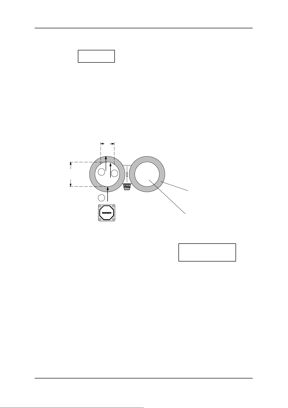
ASM 421 Technical Description6GT2 097-3AH00-0DA2
5.1 MDS recognition by field scanning
EAKO = ’0’
How field scanning works
The SLG scans the surrounding area for the presence of a data carrier. If the file handler recognizes a data
carrier, the ANW bit will be set and a Z telegram sent to the user.
After the MDS has left the transmission window, the ANW bit will be reset and a Z telegram will be sent to
the user, while the SLG scans the field for the next MDS.
If the data carrier remains exactly on the border of the transmission window, a hysteresis function ensures
the ANW bit does not continuously toggle between on/off. This hysteresis function is handled by the processor on the ASM. Read/write commands are handled completely transparently by the ASM and have no
effect on proximity detection.
B
SLG
c
L
b
b
h
Hysteresis field for
proximity detection
a
MDS
Transmission window:
Data exchange between
L, B: Dimensions of the transmission window of an SLG
read/write device at operational distance to MDS (See
manual for configuration, installation and service.)
L = Field length; B = Field width
h: Hysteresis: Area in which a just set ANW bit remains set.
MDS and SLG
h = 0.1 ... 15 mm
(depends on MDS type)
a: The point at which the mobile data carrier is detected by the SLG. The pending MOBY command will
now be processed on the MDS. The presence bit is set. The user can receive an ANW message if
required (Z message).
b: The MOBY command must be completed by this point as the data carrier is about to leave the trans-
mission window. The presence bit is still set.
c: The presence bit is reset. The user receives a Z message. The MDS has passed out of range of the
SLG.
Subject to change without notice!
RD: 03/02
J31069-D0142-U001-A0-7618
– 50 –
6GT2 002-0DA00 ASM 421 / V .24
6GT2 002-0DB00 ASM 421 / RS422
6GT2 002-0DC00 ASM 421 / TTY
Page 53
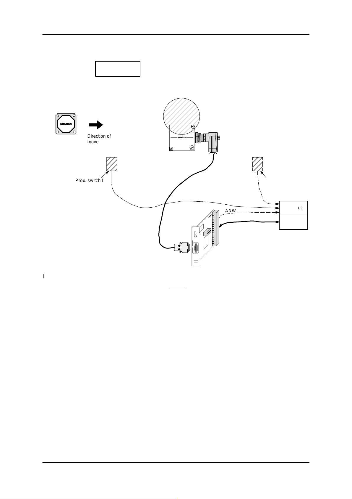
ASM 421 Technical Description 6GT2 097-3AH00-0DA2
5.2 Without entry/exit monitoring
EAKO = ’1’
Schematic layout:
MDS
Direction of
movement of
MDS
Prox. switch I
SLG
ASM 421
ANW
Prox. switch II
Dig. input
Computer
or PC
In this mode of operation, the user must ensure (e.g.using proximity switch I) that an MDS is guaranteed to
be present in the transmission window of the SLG before an MDS command is sent to the ASM. Any command now sent to the ASM will be executed immediately . If the ASM 421 does not find an MDS (presence
bit = 0), the command will immediately be terminated with an error. This also occurs if the MDS is defective. No NEXT command is required when MDS processing is complete. The computer is responsible for
controlling the entry and exit of the MDS.
Proximity switch II at the exit point is not absolutely necessary. The notification that an MDS has left the
transmission window is provided by the ASM 421 through the ANW bit and/or the Z message.
6GT2 002-0DA00 ASM 421 / V .24
6GT2 002-0DB00 ASM 421 / RS422
6GT2 002-0DC00 ASM 421 / TTY
– 51 –
Subject to change without notice!
RD: 03/02
J31069-D0142-U001-A0-7618
Page 54
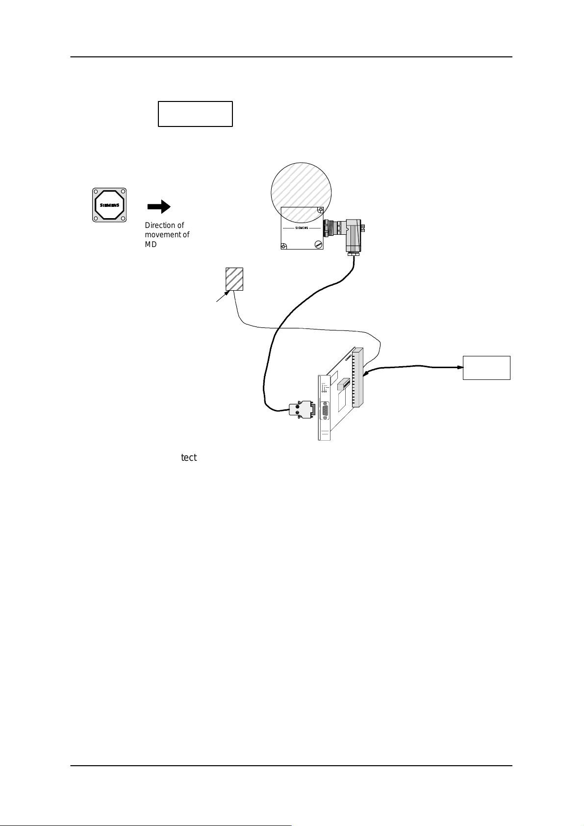
5.3 MDS control using field scanning and 1 DI
EAKO = ’2’
Schematic layout:
ASM 421 Technical Description6GT2 097-3AH00-0DA2
MDS
Direction of
movement of
MDS
Prox. switch
on DI 0
SLG
Computer
or PC
ASM 421
The entry of an MDS is detected by a proximity switch connected to DI 0. The switch should be positioned
so that the MDS is guaranteed to be in the transmission window if the switch is activated. If this is not the
case, or if the MDS is defective, an error will be reported. After processing the MDS, it is imperative that
the user send a NEXT command to the ASM. The file handler assumes complete and continuous control
of the MDS.
Subject to change without notice!
RD: 03/02
J31069-D0142-U001-A0-7618
– 52 –
6GT2 002-0DA00 ASM 421 / V .24
6GT2 002-0DB00 ASM 421 / RS422
6GT2 002-0DC00 ASM 421 / TTY
Page 55
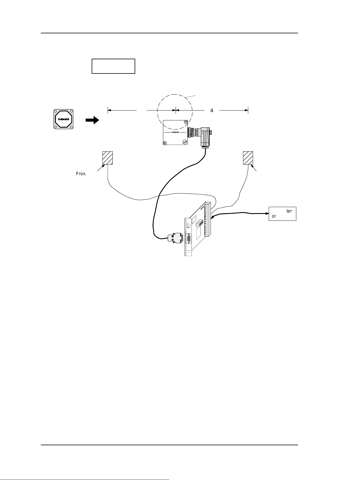
ASM 421 Technical Description 6GT2 097-3AH00-0DA2
5.4 MDS control using 2 DIs
EAKO = ’3’
Schematic layout:
Transmission window; no significance for
entry/exit monitoring
e
a
AE
MDS
Direction of
movement of
MDS
Prox. switch
on DI 0
SLG
Prox. switch
on DI 1
Computer
or PC
ASM 421
Entry (E) of an MDS is detected by a proximity switch connected to DI 0. The MDS does not have to be
within the transmission window of the SLG at this time. Command processing begins as soon as the MDS
enters the transmission window. The MDS can move anywhere between points A and E without causing
an error. When the MDS reaches point A (exit), the ASM 421 receives an impulse via DI 1. The ANW bit is
reset. The MDS has passed the Exit.
e, a: The distances from the SLG to the entry and exit proximity switches can largely be chosen at will by
the user. Note, however, that two MDSs can never be between points E and A at the same time.
After processing each MDS, it is imperative that the user sends a NEXT command. The file handler assumes complete and continuous control of the MDS. An error will be reported if:
– the MDS is defective
– two MDSs in succession have passed point E (or the same MDS twice)
– two MDSs in succession have passed point A (or the same MDS twice)
– if no NEXT command is issued following an E-A sequence
Note:
After a RESET, the presence of an MDS will only be detected (ANW bit = 1) if it is already within the transmission window of the SLG!
6GT2 002-0DA00 ASM 421 / V .24
6GT2 002-0DB00 ASM 421 / RS422
6GT2 002-0DC00 ASM 421 / TTY
– 53 –
Subject to change without notice!
RD: 03/02
J31069-D0142-U001-A0-7618
Page 56
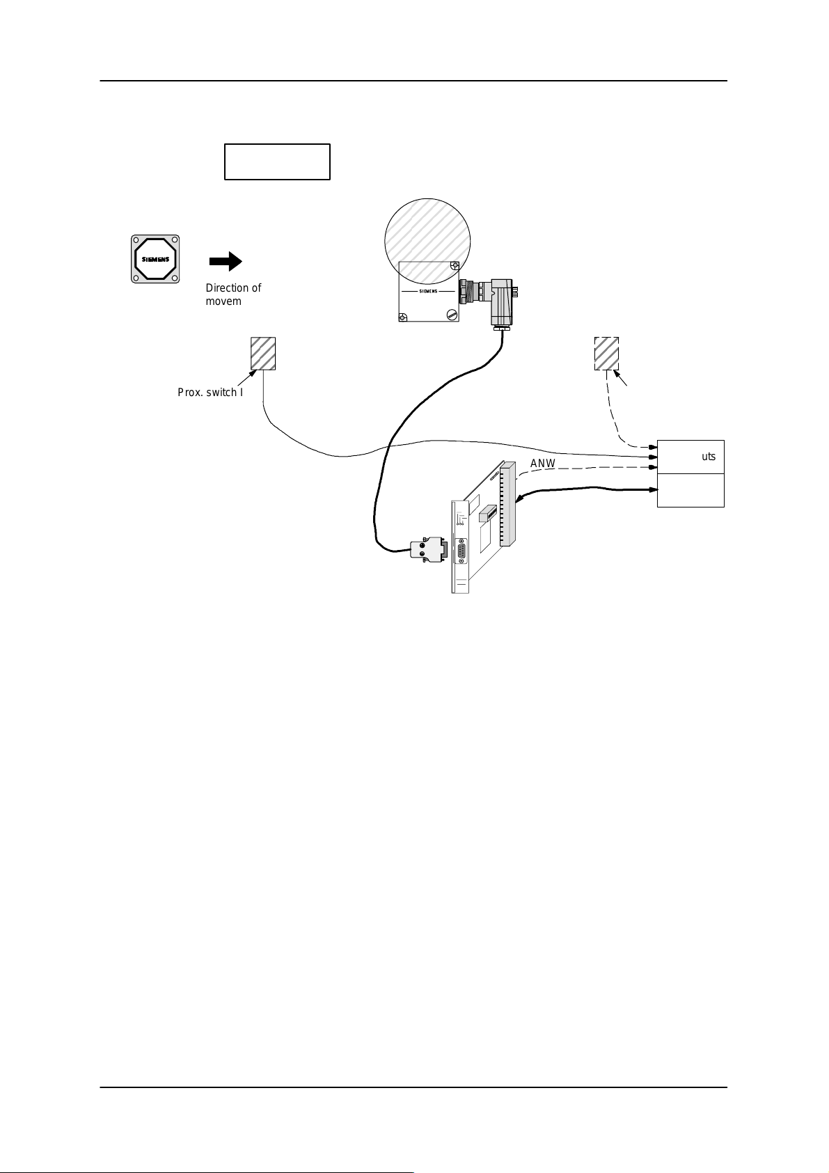
5.5 Without entry/exit monitoring
EAKO = ’4’
ASM 421 Technical Description6GT2 097-3AH00-0DA2
MDS
Direction of
movement of
MDS
Prox. switch I
SLG
ASM 421
ANW
Prox. switch II
Dig. inputs
Computer
or PC
In this mode of operation, the user assumes control of the MDS. Proximity switch I signals to the computer
that an MDS has entered. The MDS does not have to be within the transmission window of the SLG at this
time. Command processing begins as soon as the MDS enters the transmission window. The user can
check this by interrogating the ANW bit or the Z message.
Proximity switch II at the MDS exit point is not absolutely necessary.
Subject to change without notice!
RD: 03/02
J31069-D0142-U001-A0-7618
– 54 –
6GT2 002-0DA00 ASM 421 / V .24
6GT2 002-0DB00 ASM 421 / RS422
6GT2 002-0DC00 ASM 421 / TTY
Page 57
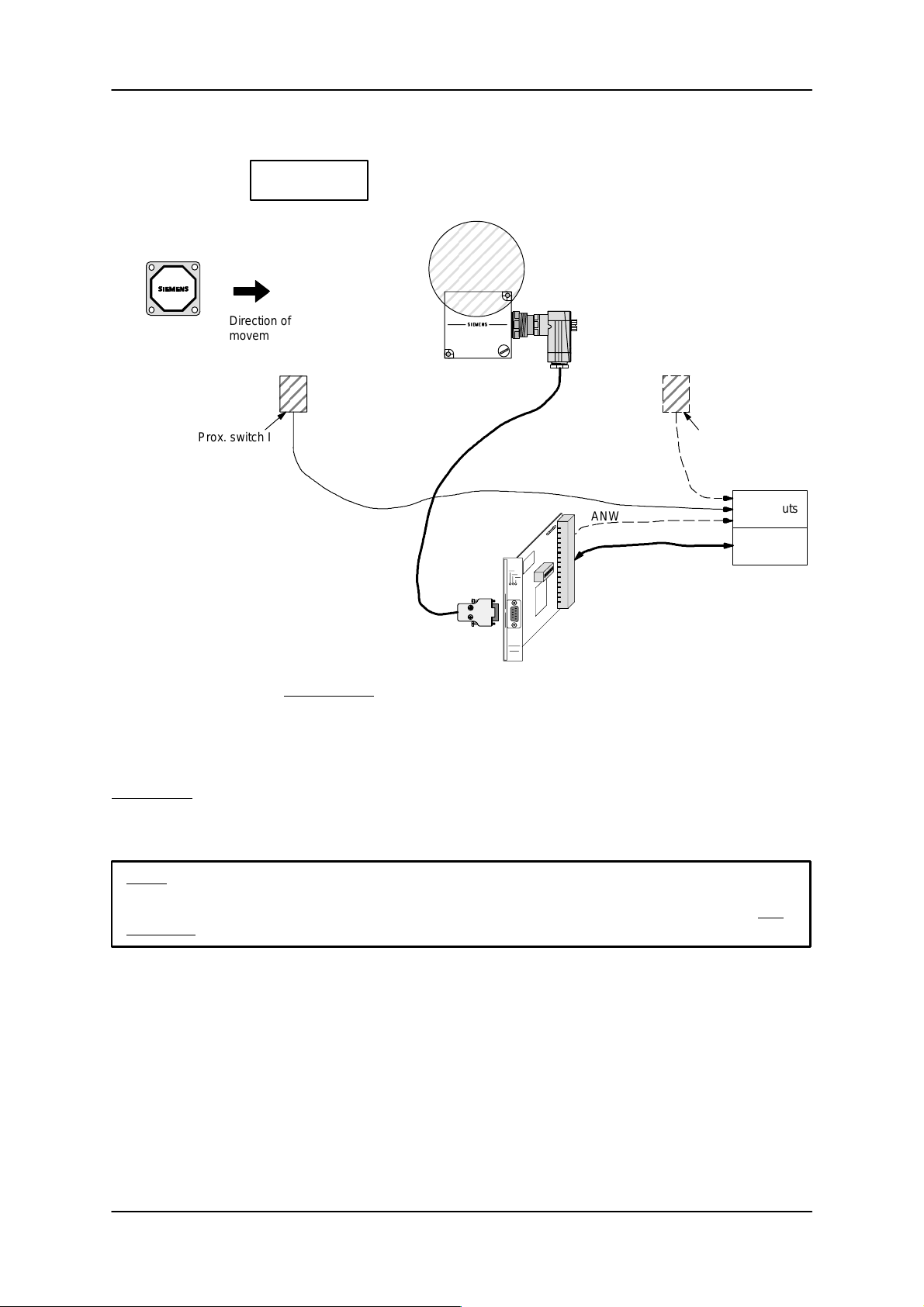
ASM 421 Technical Description 6GT2 097-3AH00-0DA2
5.6 Special Operating Mode (Test Operation)
EAKO = ’5’
MDS
Direction of
movement of
MDS
Prox. switch I
SLG
ASM 421
ANW
Prox. switch II
Dig. inputs
Computer
or PC
In this mode of operation absolutely no checking of MDS entry/exit is carried out by the file handler. The
MDS control must be handled entirely by the user.
If a command is issued to the file handler, it will be stored until an MDS arrives in the transmission window
of the SLG. The file handler then commences the processing of the command. When executing commands that do not change the DIR + FAT structure (i.e. no change to the checksum), the system area is
not updated. This increases the processing speed in especially time-critical applications, e.g. ECC operation of EEPROM MDS.
Operating with EAKO 5 automatically precludes the use of the NEXT command.
Note:
The use of EAKO 5 is a special mode of operation and it should therefore be regarded as test
operation.
6GT2 002-0DA00 ASM 421 / V .24
6GT2 002-0DB00 ASM 421 / RS422
6GT2 002-0DC00 ASM 421 / TTY
– 55 –
Subject to change without notice!
J31069-D0142-U001-A0-7618
RD: 03/02
Page 58
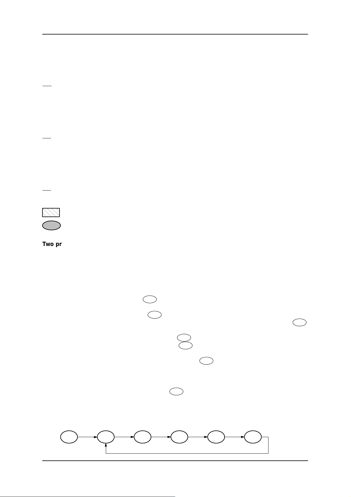
ASM 421 Technical Description6GT2 097-3AH00-0DA2
5.7 Diagram showing possible MDS states at an SLG
The following codes are used in the diagram on the following page:
MD MDS absent
MDN new/next MDS present
MDA current or old (no longer current) MDS present
BD Command present (the user has already transmitted an MDS command to the MDS)
BD Command not present (the ASM is not processing an MDS command from the user)
BIA Command in progress (a command is now being executed)
ND “Next MDS bit” set in the file handler (the ASM has received a NEXT command from the
user).The processing of all subsequent commands takes place only with the next/new
MDS.
ND “Next MDS bit” not set in the file handler (the ASM has not yet received a NEXT
command).
File handler action
Status at an SLG station.
Two process sequences will be described as examples:
A EAKO = 0; an MDS is present in the transmission window of the SLG on restart. The file “switch” is
to be read dynamically by the SLG. The computer sets a switch (points) and then waits for the next
MDS.
1. After a Restart and a RESET command from the user, the file handler writes the SLG no. to the
MDS and goes into status
. ANW bit = 1.
3
2. The user sends the READ “switch” command to the ASM. The file handler starts the command and changes to status
3. After executing the command, the ASM sends the data it has read and goes into status
27
.
3
4. After evaluating the data the user sets a switch (points). The MDS has meanwhile left the
transmission window of the SLG: status
5. The user sends a NEXT command: status
; ANW bit = 0
5
. The processing of the MDS is now complete.
11
6. Immediately after the NEXT command, the user sends the command READ “switch”. The
command is temporarily stored in the ASM: status
. This status remains until a new MDS
23
enters the transmission window of the SLG.
7. A new MDS enters the transmission window of the SLG: ANW bit = 1. The file handler begins
processing immediately: the SLG number is written to the MDS and the execution of the command READ “switch” initiated: status
27
.
8. This point is identical to point 3. The MDS processing cycle restarts from the beginning.
.
Status diagram for this application, provided no error occurs:
3 27 3 5 11 23
Subject to change without notice!
RD: 03/02
J31069-D0142-U001-A0-7618
– 56 –
6GT2 002-0DA00 ASM 421 / V .24
6GT2 002-0DB00 ASM 421 / RS422
6GT2 002-0DC00 ASM 421 / TTY
Page 59
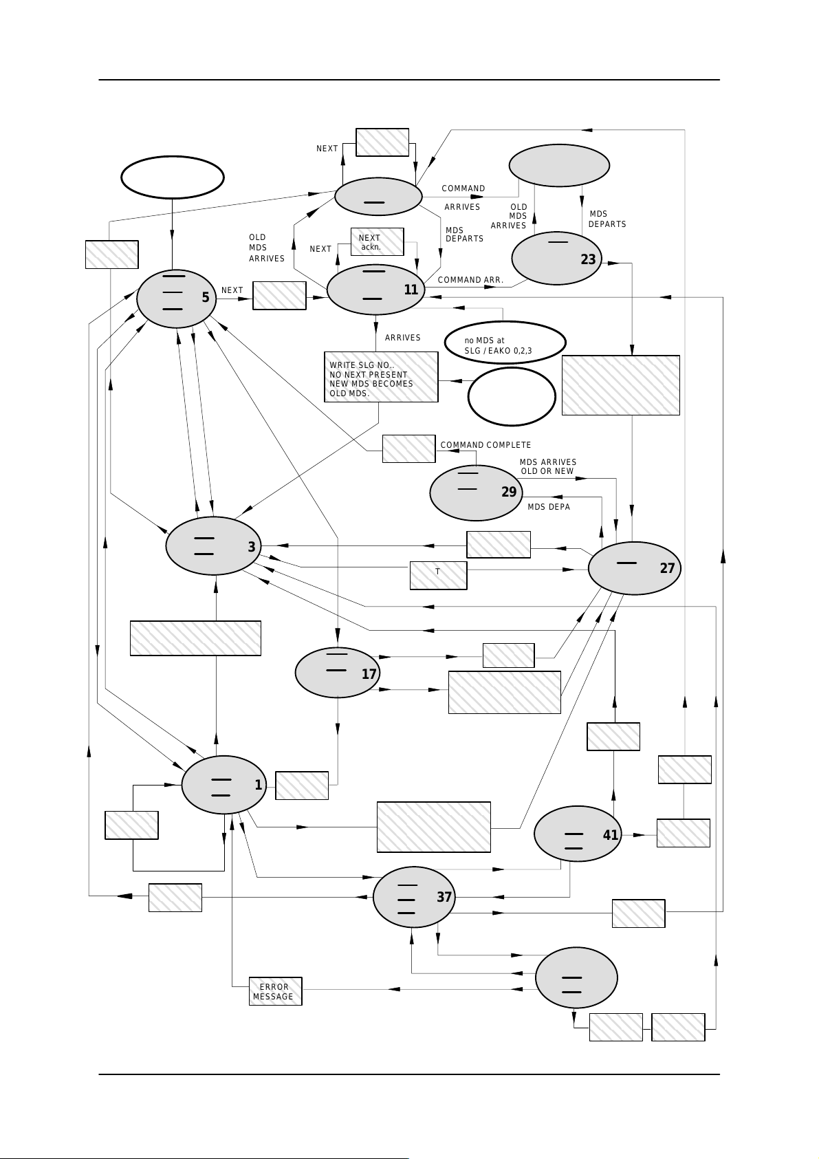
ASM 421 Technical Description 6GT2 097-3AH00-0DA2
NEXT
ackn.
MDA
ND
BD
NEXT
ackn.
MD
ND
BD
NEW MDS
ARRIVES
WRITE SLG NO..
NO NEXT PRESENT
NEW MDS BECOMES
OLD MDS.
9
11
9
COMMAND
ARRIVES
MDS
DEPARTS
COMMAND ARR.
ARRIVES
RESET
no MDS at
SLG / EAKO 0,2,3
old or new
MDS at SLG
OLD
MDS
RESET
MDA
ND
21
BD
MDS
DEPARTS
MD
23
ND
BD
ARRIVES
WRITE SLG NO..
NO NEXT PRESENT
NEW MDS BECOMES
OLD MDS.
START COMMAND.
NEW
MDS
NEXT
ackn.
RESET
no MDS at
SLG / EAKO 1,4
MD
ND
BD
NEXT
OLD
MDS
ARRIVES
NEXT
5
NEXT
ackn.
NEXT
DEPARTS
NEXT
ACKNOWLEDGE NEXT
WRITE SLG NO.
NEW MDS BECOMES OLD
NEW MDS
DEPARTS, WITH
EAK0 = 1,4
NEW
MDS
ARRIVES
ERROR
MESSAGE
COMMAND ARRIVES
WITH EAKO = 0,2,3
ERROR
MESSAGE
MDS
MDA
ND
BD
OLD MDS
ARRIVES
NEXT
MDN
ND
BD
3
COMMAND
ARRIVES
MD
ND
BD
ERROR
1
MESSAGE
COMMAND ARRIVES
WITH EAKO = 1,4
MDS DEPARTS / EAKO= 0,2,3
COMMAND ARRIVES
MESSAGE
COMMAND
ARRIVES
OLD MDS ARRIVES
17
NEW MDS
WITH EAKO = 1,4
NEW MDS
ARRIVES WITH
EAKO = 0,2,3
WRITE SLG NO..
START COMMAND
NEW MDS BCOMES
OLD MDS.
ERROR
START
COMMAND
ARRIVES
ERROR
MD
ND
BD
COMMAND COMPLETE
MD
ND
29
BIA
ACKNOW.
COMMAND
START
COMMAND
WRITE SLG NO..
START COMMAND
NEW MDS BECOMES
OLD MDS.
OLD MDS ARRIVES
OLD MDS DEPARTS
37
NEXT
MDS ARRIVES
OLD OR NEW
MDS DEPARTS
COMMAND
COMPLETE
ERROR
MDA
ND
BD
ERROR
MESSAGE
COMMAND
ARRIVES
MDA
ND
BIA
41
NEXT
MESSAGE
ERROR
27
NEXT
ackn.
ERROR
MESSAGE
ERROR
MESSAGE
6GT2 002-0DA00 ASM 421 / V .24
6GT2 002-0DB00 ASM 421 / RS422
6GT2 002-0DC00 ASM 421 / TTY
NEW MDS ARRIVES
NEW MDS DEPARTS
COMMAND ARRIVES
– 57 –
NEXT
ERROR
MDN
39
ND
BD
ERROR
MESSAGE
Subject to change without notice!
J31069-D0142-U001-A0-7618
NEXT
ackn.
RD: 03/02
Page 60
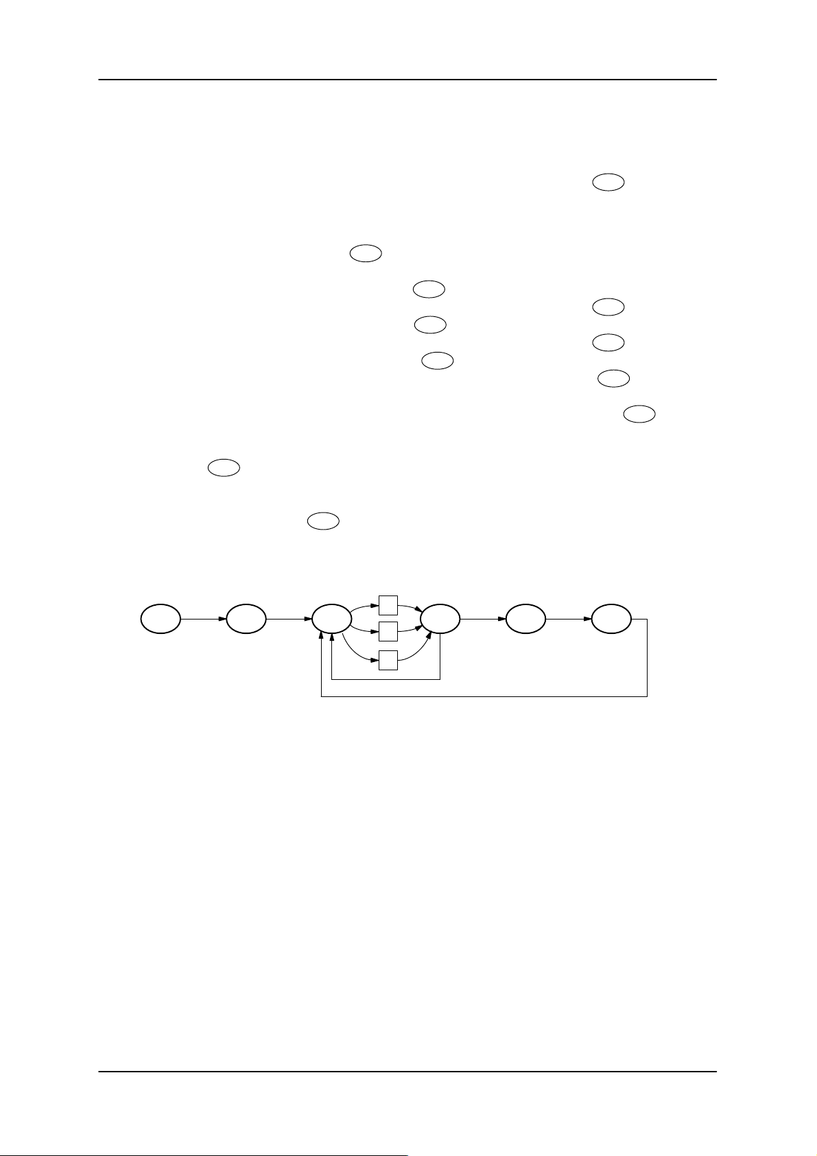
ASM 421 Technical Description6GT2 097-3AH00-0DA2
B EAKO = 1; The user assumes control of the MDS. No MDS is in the transmission window of the
SLG on restart. Processing of the MDS takes place statically. The process consists of the
commands: read “file A”, read “file B” and write “file C”.
1. After restart and RESET from the user, the file handler has the status
11
.
2. The user detects the presence of a new MDS via a proximity switch connected to a digital input
(DI) and stops the conveyor. At the same time, the file handler detects a new MDS: ANW
bit = 1. The file handler begins processing the MDS: the SLG no. is written to the MDS. The
file handler changes to status
.
3
3. The user begins to process the commands : The command READ “file A” is sent to the ASM
and is started by the file handler: Status
4. Acknowledgement of command READ “file A” sent to the user: status
5. Command READ “file B” to ASM: status
6. Acknowledgement of command READ “file B” sent to the user: status
7. Command WRITE “file C” to ASM: status
8. Acknowledgement of command WRITE “file C” sent to the user: status
27
27
27
.
.
3
.
.
3
.
. The user has
3
now completed the processing of the MDS and restarts the conveyor.
9. The MDS leaves the transmission window of the SLG: ANW bit = 0; status
.
5
10. The user detects the presence of an MDS via a proximity switch on DI and stops the conveyor.
At the same time, the file handler recognizes the presence of a new MDS: ANW bit = 1;
status
.
1
1 1. The user begins to send off the commands: the command READ “file A” is sent to the ASM.
The file handler begins processing by writing the SLG no. to the MDS. Finally the READ command is issued: status
27
.
12. This point is identical to point 4. The MDS processing cycle restarts from the beginning.
Status diagram for this application, as long as no error occurs:
11 27 3 5 13
A
B
C
Subject to change without notice!
RD: 03/02
J31069-D0142-U001-A0-7618
– 58 –
6GT2 002-0DA00 ASM 421 / V .24
6GT2 002-0DB00 ASM 421 / RS422
6GT2 002-0DC00 ASM 421 / TTY
Page 61
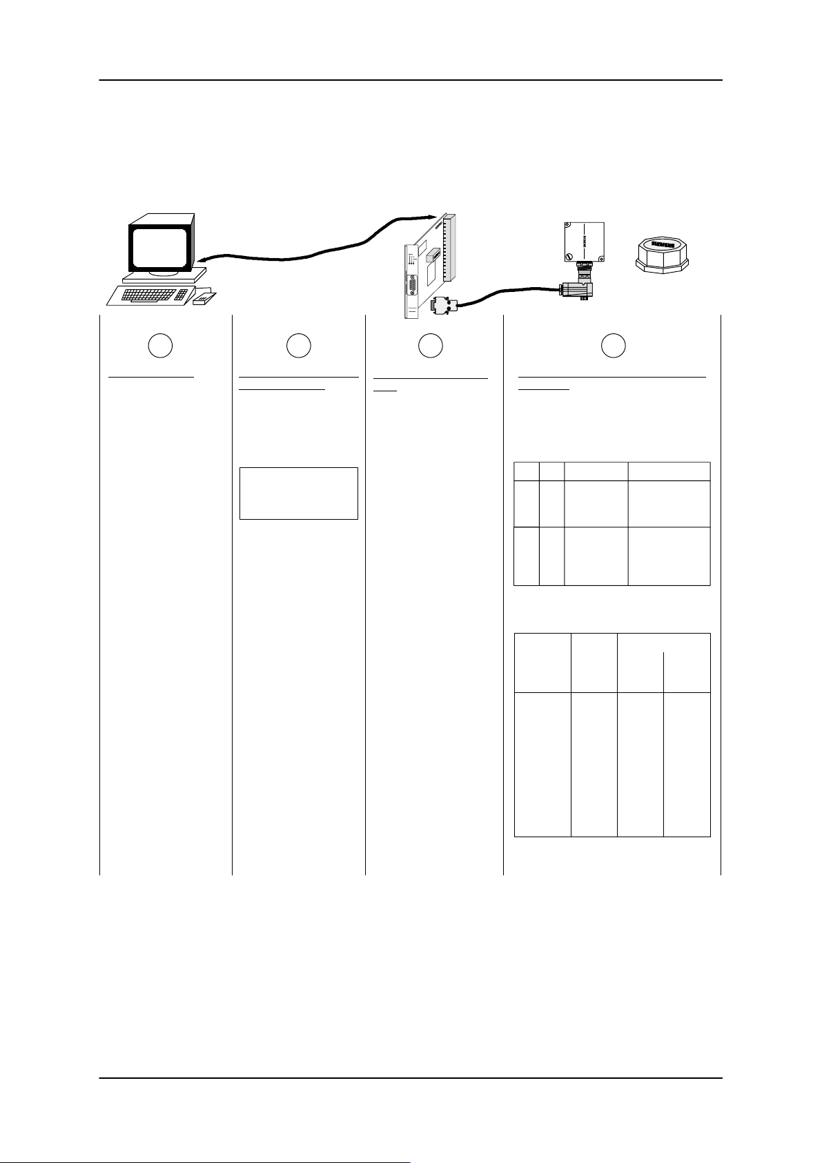
ASM 421 Technical Description 6GT2 097-3AH00-0DA2
6 System and transmission times
The following diagram shows the various timings inherent in a system:
PC ASM 421 SLG MDS
A B C D
Internal PC times:
– Processing time of
user program
– Reaction times for
acknowledgement
of 3964R procedure
These times depend on
the user system and
cannot be influenced by
MOBY.
Serial data transmission
from/to ASM 421:
– 3964R procedure
– Baud rate:
2400 Bd = 4.6 ms/byte
4800 Bd = 2.3 ms/byte
9600 Bd = 1.1 ms/byte
19200 Bd = 0.6 ms/byte
File handler processing
time:
ASM 421 processor run
time. This is very short
and can generally be ignored (< 1 msec).
Data transmission between file handler
and MDS:
– The gross data rate is 19200 baud.
– Net data rate as shown in the
following table:
1)
KtBOper. type Memory*
60 1 FH 32/2 KB R (S/L)
140 1.4 FH 8 KB E (L)
140 3.8 FH 8 KB E (S)
140 2.6 FH w. ECC 32/2KB R (L)
140 3.0 FH w. ECC 32/2KB R (S)
220 3.5 FH w. ECC 8 KB E (L)
280 8.6 FH w. ECC 8 KB E (S)
– Possible extra times for DIR and FA T
operations:
Read Write
8 KB E
without ECC
with ECC
32 KB R
without ECC
with ECC
DIR
+ FAT
580
950
940
1600
DIR
entry
300
310
330
400
DIR
entry
+ FAT
1190
1260
540
750
* R=RAM; E=EEPROM; S=write; L=read
1) Transmission time per byte
6GT2 002-0DA00 ASM 421 / V .24
6GT2 002-0DB00 ASM 421 / RS422
6GT2 002-0DC00 ASM 421 / TTY
– 59 –
2 KB R
without ECC
with ECC
Times i n msec
295
510
137
227
Subject to change without notice!
J31069-D0142-U001-A0-7618
237
420
RD: 03/02
Page 62
ASM 421 Technical Description6GT2 097-3AH00-0DA2
Example:
You want to know how much time elapses from the start of a read operation until the data is in the PC
memory. The file to be read has a length of 350 bytes and is to be transmitted in 2 blocks. The maximum
block length to the PC is 255 bytes. The mobile data carrier is an MDS 505 (32 kB). It is in the transmission
window of the SLG. The data rate between PC and ASM is 4800 baud.
The command sequence can be divided into the following time slices:
Description
1) Issuing the read command and start of command by the 3964R
driver in the PC
2) Transmission of the command to the ASM:
25 user bytes + 6 procedure bytes
(response times in PC set to zero)
3) File handler processing time
4) Processing time of the MDS by the file handler
a) on the first occasion, when the MDS directory does not yet exist
in the ASM
b) reading of 244 bytes file data (60 ms + n * 1 ms)
5) Transmission of data to the PC:
(244 + 11) bytes user data + 6 procedure bytes
(the acknowledgement times in the PC are set to zero)
6) Processing time in the PC and issuing the second command segment to the 3964R driver
7) Transmission of the second command segment to the ASM:
11 user bytes + 6 procedure bytes
(response times in PC set to zero)
8) File handler processing time
Time in ms
Application
71
––
(940)
304
600
Application
39
––
See diag.
page 59
A
B
C
D
B
A
B
C
9) Processing time of the MDS by the file handler:
Reading of 106 bytes (n * 1 ms)
(Reading the directory is definitely no longer necessary; the constant time for the processing of the system area of an MDS is not
required for each subsequent command segment)
10) Transmission of data to the PC:
(106 + 11) bytes user data + 6 procedure bytes
(acknowledgement time in the PC is set to zero)
11) Processing time in the PC until the data is available to the user
Total time of the read operation
(the times of the PC are set to zero;
the directory already exists on the ASM)
– Read times between ASM and MDS
– Communications between PC and ASM
Subject to change without notice!
RD: 03/02
J31069-D0142-U001-A0-7618
– 60 –
106
283
Application
D
B
A
1403
410
993
6GT2 002-0DA00 ASM 421 / V .24
6GT2 002-0DB00 ASM 421 / RS422
6GT2 002-0DC00 ASM 421 / TTY
Page 63
ASM 421 Technical Description 6GT2 097-3AH00-0DA2
7 Troubleshooting and error messages
An error message from the file handler always has the same format. The presence of an error is always
indicated in the status byte (5th byte) of the acknowledgement telegram. It is 4 bytes long and in ASCII
format.
Acknowledgement with error:
0 1 2/3 4 5 6/7 8/9 10
CC Status ADB DBN DBL
00 xx xxxx xxxx
’x’
Error flag is set (Bit 0 in status byte = 1)
The error flag must always be interrogated by the user
Command code showing where the error occurred
xxxx 0401
When terminated within a block sequence the block in which the
error was detected is shown here.
A block sequence will automatically be interrupted by an error
11/14
Error code
Error number: 000 ... 999
Error group: A = Protocol error
B = SLG error
C = MDS error
D = Task related error
E = Directory error
F = File related error
K = Error in the OUEUE-WRITE command
In general: – An error terminates block creation
– There are no “ignore” or “retry” options
– A “RESET” is not necessary following an error
– The parameters ADB and DBN contain the block number in which the error occurred
– If using the LOAD command:
a LOAD command should be programmed after each error
(As a rule, the directory in the ASM is invalid if the error occurred during a directory
operation. If the error occurred in the data area, the directory in the ASM remains valid. If many errors occur, however, the user cannot know exactly whether the error occurred during the DIR processing or while processing the user data).
6GT2 002-0DA00 ASM 421 / V .24
6GT2 002-0DB00 ASM 421 / RS422
6GT2 002-0DC00 ASM 421 / TTY
– 61 –
Subject to change without notice!
RD: 03/02
J31069-D0142-U001-A0-7618
Page 64

ASM 421 Technical Description6GT2 097-3AH00-0DA2
The following table contains a summary of all the errors from the ASM 421:
flashes of
red LED
3
4
2
5
6
7
8
10
11
12
13
14
15
Error messages from the file handler
A0 06 Unknown error, the command code CC is invalid
A0 11 DBN not equal to 1 in first command block; CC or DBN incorrect for subsequent blocks;
DBL is wrong or does not fit the transferred data length.
A0 15 Reserved
A0 16 Command from another user being processed
B0 01 Fault in connection to the SLG
B0 02 1. Error when EAKO = 1; no MDS present (Timeout)
2. New MDS in transmission window; no NEXT command but command started (EAKO = 0,2)
3. New MDS has left station without NEXT (EAKO = 0,2)
4. EAKO = 2: MDS entry detected; however no MDS is to be found within the transmission
window
B0 05 EAKO = 3: An MDS has exited the transmission window without having entered it previously.
B0 06 EAKO = 3: new MDS arrives while the old one is still in the transmission window
B0 07 EAKO = 3: 2 x MDS entered without one having exited
C0 02 RAM error in MDS
C0 06 Proximity error
C0 07 Incorrect parameters in TRACE or FORMAT / command cannot be interpreted
C0 08 Too many sync attempts
C0 09 Too many send errors
C0 10 CRC send error
C0 11 reserved
C0 12 FORMAT, cannot initialize MDS
C0 13 FORMAT, timeout
C0 14 FORMAT, not initialized
C0 15 CMD address error
C0 16 ECC error
C0 17 General driver error
Kind of
error
PROTOCOL
ERROR
SLG
ERROR
MDS
ERROR
D0 01 Only RESET command permissible
1
D0 05 Invalid file or volume name
D0 07 The directory specified in the LOAD command is invalid; MOVE command isn’t possible
D0 09 Incorrect parameter in RESET command
D0 14 CREATE and WRITE: the user data area in the MDS is full
D0 15 Only FORMAT command possible; MDS not identified
D0 18 Start address in the command is outside the data area (start address > file length)
D0 22 Directory and/or FAT-changing access to an MDS protected with COVER is illegal.
D0 23 COVER: MDS name is incorrect.
E0 01 The MDS type is incorrect or unsuitable for the selected mode of operation (ECC).
E0 02 CREATE command; no more directory entries available
E0 03 CREATE command; file already exists in directory
E0 05 FAT block error detected in READ or WRITE; FAT is incorrect.
F0 01 Specified data not present
F0 05 WRITE error in file with “Read only” or “Write once” attribute
F0 06 Incorrect access rights or switch setting
Kx xx 1. xxx = Number of the incorrect filr entry (See QUEUE-WRITE).
2. QUEUE-WRITE command in parameterized incorrectly.
3. The file to be set up already exists.
–––– The ASM has a receive error
27
–––– The ASM has a send error
28
* Errors with no digits in this column do not cause the red LED to flash.
TASK-RELATED
ERROR
DIRECTORY-
RELATED
ERROR
FILE-
RELATED
ERROR
QUEUE
PARA-
METERIZATION
SERIAL
INTERFACE
Subject to change without notice!
RD: 03/02
J31069-D0142-U001-A0-7618
– 62 –
6GT2 002-0DA00 ASM 421 / V .24
6GT2 002-0DB00 ASM 421 / RS422
6GT2 002-0DC00 ASM 421 / TTY
Page 65

ASM 421 Technical Description 6GT2 097-3AH00-0DA2
Full error description
A0 06: The command code for the started command is not valid (not defined). The correct CC must
be entered (see section 3.4).
A0 11: – for the first command block: DBN (= byte 8/9 in the telegram) does not have the value
0001.
– for subsequent block: DBN from the user is not in the correct ascending sequence or the
CC parameter (= byte 4) is not appropriate for the command now being processed.
A0 16: The file handler is currently processing a command from another user. Command processing
will be delayed until the other user is finished. The command may have to be issued again.
B0 01: Fault in connection to the SLG.
– cable between ASM and SLG is incorrectly wired or cable is damaged
– 24 V supply is not connected or is switched off
– fuse on the ASM is defective
– Hardware fault: ASM 421 or SLG
This error does not occur at the start of the system commands (RESET, NEXT,
ASM STATUS).
B0 02: EAKO 1, 2: – A command has been started, but there is no MDS in the transmission
window of the SLG.
– MDS 507; dialog battery is dead (Batt2 bit is not set; measure battery
voltage).
EAKO 0, 2, 3: – the old/current MDS is out of the transmission window and the next/new
MDS has entered the transmission window. A command has been started
(not NEXT). This command refers to the new MDS, but the old/current
MDS has not been terminated with NEXT.
– a new MDS entered the transmission window of the SLG and left it again
without any command being processed. (MDS has “slipped through”).
EAKO 2: The arrival of an MDS was recognized by the proximity switch on DI 0; how-
ever no MDS is to be found in the transmission window of the SLG.
B0 05: Only when EAKO (I/O Control) = 3:
No MDS is to be found between points E and A; in this state the departure proximity
switch has been activated.
– an MDS has exited the transmission window without having entered it previously.
– after the departure of an MDS, the MDS has been moved back and the departure proxi-
mity switch activated a second time.
B0 06: Only when EAKO = 3: MDS generates an entry signal at DI0 but the old MDS has not exited
completely.
– entry (DI0) and exit (DI1) proximity switches are being triggered simultaneously
– entry and exit are too close together
B0 07: Only when EAKO = 3: two MDS entries have occurred at DI0, but no MDS exited at DI1
– entry and exit are too close together
– an MDS is stationary directly after entry and is moved backwards slightly by the
conveyor
6GT2 002-0DA00 ASM 421 / V .24
6GT2 002-0DB00 ASM 421 / RS422
6GT2 002-0DC00 ASM 421 / TTY
– 63 –
Subject to change without notice!
RD: 03/02
J31069-D0142-U001-A0-7618
Page 66

ASM 421 Technical Description6GT2 097-3AH00-0DA2
C0 02: Memory error message from MDS.
The MDS has not yet been written or has lost its memory content due to battery failure (not
with EEPROM MDS). Therefore:
– change the MDS (if the battery monitoring bit is set)
– initialize the MDS with the STG 4F
– format the MDS using the FORMAT command
C0 06: During certain important operations (e.g. writing system area of MDS, formatting MDS) the
MDS must not leave the transmission window of the SLG, as otherwise the command will
terminate with this error. Therefore:
– issue the command again
– MDS is standing in the border zone of the SLG transmission window
– at EAKO = 1: The MDS is not in the transmission window of the SLG at the start of a
command.
C0 07: – The FORMAT or TRACE commands have been issued with incorrect parameters. The
physical address requested does not exist in the MDS (MDS memory is smaller than specified in the command)
– With READ/WRITE/UPDATE: the pointer in the FAT is incorrect; it is pointing to a block
that does not exist in the MDS.
C0 08: Field interference at the SLG. The SLG is receiving interference impulses from the surround-
ing area
– external interference field; the interference field can be detected by the “inductive field
indicator” of the STG.
– the distance between two SLGs is too small and does not conform to the design guidelines
– the connection cable to the SLG is subject to interference, is too long or does not conform
to specification
Or MDS 507; dialog battery is dead
– Check Batt2 bit
– Measure voltage on battery.
C0 09: Too many send errors have occurred. The MDS could not receive the command or the data
from the SLG correctly, despite several attempts
– the MDS is standing exactly on the edge of the transmission window
– data transmission to the MDS is being affected by external interference
C0 10: – CRC send error. The monitoring system has detected a data transmission error . Cause of
error as for C0 08.
– The MDS reports CRC errors very frequently. (MDS is on the edge of a transmission
window. MDS or SLG is defective.)
C0 12: The MDS cannot execute the FORMAT command. The MDS is defective.
C0 13: The MDS must be in the SLG field when formatting, otherwise a timeout error occurs, i.e.:
– the MDS is standing exactly on the edge of the transmission window
– the MDS is using too much current (defective).
– EEPROM-MDS type parameterized incorrectly in FORMAT
Or MDS 507; dialog battery is dead
– Check Batt2 bit
– Measure voltage on battery.
Subject to change without notice!
RD: 03/02
J31069-D0142-U001-A0-7618
– 64 –
6GT2 002-0DA00 ASM 421 / V .24
6GT2 002-0DB00 ASM 421 / RS422
6GT2 002-0DC00 ASM 421 / TTY
Page 67

ASM 421 Technical Description 6GT2 097-3AH00-0DA2
C0 14: The MDS memory cannot be written
– the MDS has a smaller memory than specified in the FORMAT command, i.e. enter the
correct parameters for this type of MDS
– the MDS memory is defective
– an EEPROM MDS has been written too often and has reached the end of its life
C0 15: Address error. The address area of the MDS has been exceeded
– the MDS is not of the correct type
C0 16: An ECC error has occurred. Data cannot be read from the MDS
– the MDS has lost its data (MDS defective)
– the MDS was not formatted by the ECC driver. Reformat the MDS
– an EEPROM MDS has reached the end of its life. The data has been lost. Replace the
MDS
– The MDS left the field during the write access. The MDS is not positioned correctly.
C0 17: The file handler is not working correctly
– check command format and command sequence
– the ASM 421 hardware (firmware) is defective (faulty).
D0 01: The file handler will only accept RESET commands
– the file handler has not yet been initialized by a RESET command
– this situation can only be remedied by a RESET command
D0 05: The FORMAT, CREATE, ATTRIB, WRITE, UPDATE, COVER and QUEUE-WRITE com-
mands have been issued with incorrect parameters
– FORMAT with invalid volume name or MDS type
– CREATE with invalid file name
– invalid file attribute
– WRITE/UPDATE with length 0 (DLNG=0)
– QUEUE-WRITE with invalid option
– COVER with invalid user (Only 1 and 2 are valid.)
D0 07: The data transferred by the LOAD command is incorrect:
– the data from DIR + FAT do not match the transmitted checksum.
– the DLNG is parameterized incorrectly in LOAD.
MOVE command: the DIR + F AT do not fit the checksum. A MOVE command cannot be carried out. The data structure on the MDS may be faulty. Format the MDS.
D0 09: The RESET command has been transmitted to the file handler with incorrect parameters
– check bytes 11 to 17 of the telegram as shown in section 3.4.15
D0 14: WRITE command: there is no longer enough memory available in the MDS. Not all the
data has been written to the MDS
CREATE command: no data blocks can be reserved when creating a file. No more blocks
are free
D0 15: The MDS could not be identified by the file handler. Reformat the MDS.
D0 18: The physical address requested lies outside the file. There is an error in the FAT. Reformat
the MDS.
D0 22: The MDS is protected by the COVER command. A write command (e.g. UPDATE, CREATE)
must not modify the memory structure and is therefore rejected.
6GT2 002-0DA00 ASM 421 / V .24
6GT2 002-0DB00 ASM 421 / RS422
6GT2 002-0DC00 ASM 421 / TTY
– 65 –
Subject to change without notice!
RD: 03/02
J31069-D0142-U001-A0-7618
Page 68

ASM 421 Technical Description6GT2 097-3AH00-0DA2
D0 23: COVER command: the MDS name specified in the command does not correspond to the
actual MDS name.
E0 01: – the type of MDS present at the SLG does not correspond to the ECC operating mode se-
lected. The MDS must be reformatted to correspond to the desired ECC operating mode.
– the MDS is not a file handler MDS. Format the MDS.
E0 02: No more directory entries available. The file specified in the CREATE command cannot be
created.
→ see table in Chapter 1
E0 03: The file specified with the CREATE command already exists in the directory (no duplicate
names).
E0 05: A FAT block sequence error has been detected with a READ or WRITE command. The file
allocation table (FAT) is incorrect. The MDS must be reformatted.
F0 01: Incorrect address with TRACE command.
– the file addressed by a command (e.g. WRITE) does not exist in the directory . The file must
be created with CREATE.
– check file name (perhaps not in ASCII format)
F0 05: Attempt to write (WRITE command) to a read-only file (protected by an appropriate attri-
bute).
– change the access rights with the ATTRIB command and then issue the WRITE/DELETE/
UPDATE command again
F0 06: The RWD switch on the ASM does not give sufficient rights for this command. The command
will be ignored → check switch according to section 2.3.
Kx xx: QUEUE WRITE parameter incorrect (check command telegram)
Option 0000 Hex: The file entry with number xxx or xxx + 1 parameterized in the command
telegram is incorrect. The method of counting the file entries in the
command telegram begins with 1.
Option 0001 Hex: The file entry with number xxx or xxx + 1 parameterized in the command
telegram contains a file name that already exists on the MDS. The
method of counting the file entries in the command telegram begins
with 1.
Note: The file entries are counted in decimal format.
Subject to change without notice!
RD: 03/02
J31069-D0142-U001-A0-7618
– 66 –
6GT2 002-0DA00 ASM 421 / V .24
6GT2 002-0DB00 ASM 421 / RS422
6GT2 002-0DC00 ASM 421 / TTY
Page 69

ASM 421 Technical Description 6GT2 097-3AH00-0DA2
8 Warnings
English
!
Hazardous voltages are present in this equipment during operation.
To ensure safe operation of the equipment, maintenance shall only be
performed by qualified personnel in accordance with the instructions
in the MOBY catalog1 and technical description.
Failure to observe these instructions can result in death, severe personal injury or substantial damage to property.
The following instructions and those on all product labels must be
followed when carrying out any maintenance work.
Warning
Always disconnect and earth the equipment before starting
any maintenance.
Use only spare parts authorized by the manufacturer.
The servicing intervals as well as the instructions for repair
and replacement shall be duly observed.
A lithium battery is contained in mobile data memories with
RAM. The following instructions must be observed:
To avoid the risk of fire, explosion and severe burns, the bat-
tery should not be recharged, dismantled, exposed to heat
over 100 degrees Celsius, ignited, or brought into contact
with water.
The special instructions must be followed when using heat-resistant
data storage media.
1 Should you not be in possession of the MOBY catalog, it can be
obtained through your local Siemens office.
Deutsch
!
Beim Betrieb elektrischer Geräte stehen zwangsläufig bestimmte
Teile dieser Geräte unter gefährlicher Spannung.
Sicherer Betrieb der Geräte setzt voraus, dass diese von qualifiziertem Personal sachgemäß unter Beachtung der im MOBY-Katalog
und der technischen Beschreibung enthaltenen Hinweise eingesetzt
werden.
Bei Nichtbeachtung können Tod, schwere Körperverletzung oder erheblicher Sachschaden die Folge sein.
Beachten Sie daher auch bei Instandhaltungsmaßnahmen an diesem
Gerät alle hier und auf dem Produkt selbst aufgeführten Hinweise.
Warnung
Vor Beginn jeglicher Arbeiten ist das Gerät vom Netz zu tren-
nen und zu erden.
Es dürfen nur vom Hersteller zugelassene Ersatzteile verwen-
det werden.
Die vorgeschriebenen Wartungsintervalle sowie die Anwei-
sungen für Reparatur und Austausch sind unbedingt einzuhalten.
Bei einem mobilen Datenspeicher mit RAM ist eine Lithium-
batterie integriert, hierzu sind folgende Hinweise zu beachten:
Vermeiden Sie das Risiko von Feuer, Explosionen und schwe-
ren Verbrennungen. Die Batterie darf nicht nachgeladen, auseinandergebaut, über 100° Celsius erwärmt, entzündet oder
ihr Inhalt mit Wasser in Berührung gebracht werden.
Beim hitzefesten Datenträger sind die besonderen Hinweise zu berücksichtigen.
1 Sollten Sie nicht im Besitz des MOBY-Katalogs sein, so kann er
über jede örtliche SIEMENS-Niederlassung bestellt werden.
1
6GT2 002-0DA00 ASM 421 / V .24
6GT2 002-0DB00 ASM 421 / RS422
6GT2 002-0DC00 ASM 421 / TTY
– 67 –
Subject to change without notice!
RD: 03/02
J31069-D0142-U001-A0-7618
Page 70
Français Italiano
ASM 421 Technical Description6GT2 097-3AH00-0DA2
! !
Le fonctionnement d’un équipement électrique implique nécessairement la
présence de tensions dangereuses sur certaines de ses parties.
L’exploitation sûre de cet équipement implique qu’il soit mis en oeuvre de
façon adéquate par des personnes qualifiées, en respectant les consignes de
sécurité figurant au catalogue MOBY1 et aux descriptions techniques.
Le non-respect des consignes de sécurité peut conduire à la mort, à des
lésions corporelles graves ou à un dommage matériel important.
Ne procéder à l’entretien que dans le plus grand respect des règles de sécurité énoncées ici ou figurant sur le produit.
Attention Pericolo
Avant toute intervention, mettre l’appareil hors tension et à la terre.
N’utiliser que des pièces de rechange autorisées.
Respecter la périodicité d’entretien et les instructions de réparation
et de remplacement.
Les mémoires embarquées (RAM) sont équipées d’une pile au li-
thium.
Ne pas exposer la pile au feu, danger d’explosion et de lésions gra-
ves. La pile ne doit pas être rechargée, ouverte exposée à des
températures supérieures à 100° C ou exposée au feu. Son contenu
ne doit pas entrer en contact avec de l’eau.
En ce qui concerne les supports de données résistants à la chaleur, respecter
les consignes spécifiques.
1 Si vous ne disposez pas ou du catalogue MOBY, ce peuvent être com-
mandés auprès de votre agence SIEMENS.
Durante il funzionamento di apparecchi elettrici, determinate parti di tali
apparecchi si trovano inevitabilmente sotto tensione pericolosa.
Per un funzionamento sicuro di questi apparecchi è necessario che essi
vengano adoperati, nel modo opportuno, solo da personale qualificato,
che osservi le indicazioni contenute nel catalogo1 per gli apparecchi
MOBY e nella descrizione tecnica.
In caso di non osservanza si possono verificare la morte, gravi lesioni alle
persone o notevoli vanni alle cose.
Per questo motivo è necessario che le avvertenze riportate qui e sul prodotto stesso vengano rispettate anche nel caso di misure di manutenzione
degli apparecchi.
Prima di iniziare qualsiasi lavoro è necessario staccare l’apparec-
chio dalla rete ed effettuare una messa a terra.
Possono essere utilizzati solo pezzi di ricambio prodotti dal cos-
truttore.
E’assolutamente necessario rispettare i tempi di manutenzione
previsti e le indicazioni riguardanti il ricambio e la riparazione.
In una memoria dati mobile dotata di RAM è integrata una batte-
ria al litio; in questo caso è necessario osservare le seguenti indicazioni:
evitare il pericolo di incendio, di esplosioni e di gravi ustioni.
E’vietato ricaricare, smontare, riscaldare oltre i 100° C o incendiare la batteria, oppure mettere il suo contenuto a contatto con
acqua.
Nel caso di un supporto dati resistente al calore è necessario osservare le
indicazioni speciali al riguardo.
1 Se non doveste essere in possesso del catalogo MOBY, potete ordi-
narlo presso qualsiasi filiale SIEMENS di zona.
Español Svensk
! !
Durante el funcionamiento de los equipos eléctricos hay partes de los mismos que se encuentran forzosamente bajo tensión peligrosa.
Un funcionamiento seguro de los equipos presupone que han sido instalados correctamente por personal calificado observando las indicaciones
contenidas en el Catálogo1 de los equipos MOBY y la Descripción técnica.
La no observación de dichas indicaciones puede provocar la muerte, lesiones corporales graves o daños materiales considerables.
Por este motivo es preciso observar también durante las operaciones de
mantenimiento y reparación en dicho equipo todas las indicaciones que figuran aquí y en el producto.
Antes de comenzar cualquier trabajo es preciso seccionar de la red
Solo deben utilizarse repuestos homologados por el fabricante.
Es imprescindible observar los intervalos de mantenimiento especi-
Las memorias de datos móviles con RAM tienen integrada una
En los soportes de datos con protección térmica es preciso observar las indicaciones particulares respectivas.
1
Precaución
el equipo y ponerlo a tierra.
ficados asi como las instrucciones de reparación y reemplazo.
batería de litio; al respecto es preciso observar las indicaciones
siguientes:
Evite riesgos de fuego, explosiones y quemaduras graves. La batería no debe ser recargada, desmontada, calentada a mas de 100
grados centígrados, inflamada: su contenido no deberá ponerse en
contacto con agua.
Si no dispone del catálogo MOBY, estos pueden pedirse a través de
cualquier sucursal local de SIEMENS.
Vid drift av elektrisk utrustning ligger det alltid en farlig spänning på vissa
delar av utrustningen.
Säker drift av utrustningen förutsätter att den utförs av kvalificerad personal med uppmärksamhet på anvisningarna i MOBY-katalogen1 samt de
anvisningarsom ges i den tekniska beskrivningen.
Om dessa anvisningar ej beaktas kan följden bli dödsfall, svår kroppskada
eller avsevärda materielskador.
Uppmärksamma vid underhållsarbete också anvisningar som ges här och
på själva produkten.
Före allt arbete skall utrustningen skiljas fran nätet och jordas.
Bara reservdelar som godkänts av tillverkaren får användas.
lakttag alltid föreskrivna underhållsintervall samt de anvisningar
som givits rörande reparation och utbyte.
Det mobila dataminnet med RAM innehåller et litiumbatteri. För
detta gäller följande anvisningar:
Undvik risk för öppen låga, explosioner och förbränning. Batteriet
får inte efterladdas, tas isär, värmas upp över 100° C eller tändas
på., och dess innehåll får ej komma i beröring med vatten.
För värmebeständiga datamedier gäller speciella anvisningar, som måste
beaktas.
1 Om Ni inte har ett exemplar av MOBY-katalogen så kan den bestållas
från närmaste SIEMENS-kontor.
Varning
Subject to change without notice!
RD: 03/02
J31069-D0142-U001-A0-7618
– 68 –
6GT2 002-0DA00 ASM 421 / V .24
6GT2 002-0DB00 ASM 421 / RS422
6GT2 002-0DC00 ASM 421 / TTY
 Loading...