

Page 1

Table of Contents
MOBY
STG Hand-Held Terminal PRO
User’s Guide
General
Commissioning the
STG Hand-Held Terminal PRO
Using the
STG Hand-Held Terminal PRO
The “MOBY D/E/I”
Programs
The “FILEHANDLER”
Program
Expanded Functions
1
2
3
4
5
6
Error Messages
Technical Data
Appendix
7
8
A
(5)J31069-D0126-U001-A6-7418
Published in May 2007
Page 2

Safety Guidelines
This manual contains notices you have to observe in order to ensure your personal safety, as well as
to prevent damage to property. The notices referring to your personal safety are highlighted in the
manual by a safety alert symbol, notices referring only to property damage have no safety alert symbol. These notices shown below are graded according to the degree of danger.
Danger
!
!
!
indicates that death or severe personal injury will result if proper precautions are not taken.
Warning
indicates that death or severe personal injury may result if proper precautions are not taken.
Caution
with a safety alert symbol, indicates that minor personal injury can result if proper precautions are
not taken.
Caution
without a safety alert symbol, indicates that property damage can result if proper precautions are not
taken.
Notice
indicates that an unintended result or situation can occur if the corresponding information is not
taken into account.
If more than one degree of danger is present, the warning notice representing the highest degree of
danger will be used. A notice warning of injury to persons with a safety alert symbol may also include
a warning relating to property damage.
Qualified Personnel
The device/system may only be set up and used in conjunction with this documentation. Commissioning and operation of a device/system may only be performed by qualified personnel. Within the
context of the safety notes in this documentation qualified persons are defined as persons who are
authorized to commission, ground and label devices, systems and circuits in accordance with established safety practices and standards.
Prescribed Usage
Note the following:
Warning
!
Trademarks
Disclaimer of Liability
This device may only be used for the applications described in the catalog or the technical description and only in connection with devices or components from other manufacturers which have been
approved or recommended by Siemens. Correct, reliable operation of the product requires proper
transport, storage, positioning and assembly as well as careful operation and maintenance.
All names identified by are registered trademarks of the Siemens AG. The remaining trademarks
in this publication may be trademarks whose use by third parties for their own purposes could violate
the rights of the owner.
We have reviewed the contents of this publication to ensure consistency with the hardware and software described. Since variance cannot be precluded entirely, we cannot guarantee full consistency.
However, the information in this publication is reviewed regularly and any necessary corrections are
included in subsequent editions.
Siemens AG
Automation and Drives
Postfach 48 48
90437 Nürnberg
GERMANY
(5)J31069-D0126-U001-A6-7418
Edition 05/07
Copyright E Siemens AG 1999, 2000, 2002, 2003, 2007
Technical data subject to change
Page 3

R 05/07
Table of Contents
Table of Contents
1 General E-1. . . . . . . . . . . . . . . . . . . . . . . . . . . . . . . . . . . . . . . . . . . . . . . . . . . . .
1.1 Application Areas E-2. . . . . . . . . . . . . . . . . . . . . . . . . . . . . . . . . . . . . .
1.2 Product Description E-2. . . . . . . . . . . . . . . . . . . . . . . . . . . . . . . . . . . .
1.3 FCC Information for the USA E-4. . . . . . . . . . . . . . . . . . . . . . . . . . . .
2 Commissioning the STG Hand-Held Terminal PRO E-5. . . . . . . . . . . . .
2.1 Included Components E-5. . . . . . . . . . . . . . . . . . . . . . . . . . . . . . . . . .
2.2 Turning on the Device and Setting the Operating Mode E-6. . . . .
2.3 MOBY Applications E-7. . . . . . . . . . . . . . . . . . . . . . . . . . . . . . . . . . . .
2.4 User Interface E-7. . . . . . . . . . . . . . . . . . . . . . . . . . . . . . . . . . . . . . . . .
3 Using the STG Hand-Held Terminal PRO E-8. . . . . . . . . . . . . . . . . . . . . .
3.1 Keyboard E-8. . . . . . . . . . . . . . . . . . . . . . . . . . . . . . . . . . . . . . . . . . . . .
3.1.1 Modifier keys E-9. . . . . . . . . . . . . . . . . . . . . . . . . . . . . . . . . . . . . . . . .
3.1.2 Key functions E-9. . . . . . . . . . . . . . . . . . . . . . . . . . . . . . . . . . . . . . . . .
3.2 Antenna on the Read Head and Antenna Field E-10. . . . . . . . . . . .
3.3 Charging Function E-12. . . . . . . . . . . . . . . . . . . . . . . . . . . . . . . . . . . . .
4 The “MOBY D/E/I” Programs E-13. . . . . . . . . . . . . . . . . . . . . . . . . . . . . . . . .
4.1 Data Editor E-15. . . . . . . . . . . . . . . . . . . . . . . . . . . . . . . . . . . . . . . . . . .
4.2 MDS Functions E-18. . . . . . . . . . . . . . . . . . . . . . . . . . . . . . . . . . . . . . .
4.2.1 General Information on Read and Write-Accessing an MDS E-19.
4.2.2 Reading the MDS E-20. . . . . . . . . . . . . . . . . . . . . . . . . . . . . . . . . . . . .
4.2.3 Writing the MDS E-20. . . . . . . . . . . . . . . . . . . . . . . . . . . . . . . . . . . . . . .
4.2.4 Erasing/Initializing the MDS E-20. . . . . . . . . . . . . . . . . . . . . . . . . . . . .
4.2.5 Reading the ID Number E-20. . . . . . . . . . . . . . . . . . . . . . . . . . . . . . . .
4.2.6 Reading Raw Data E-21. . . . . . . . . . . . . . . . . . . . . . . . . . . . . . . . . . . .
4.3 File Functions E-22. . . . . . . . . . . . . . . . . . . . . . . . . . . . . . . . . . . . . . . . .
4.3.1 Loading a File E-22. . . . . . . . . . . . . . . . . . . . . . . . . . . . . . . . . . . . . . . . .
4.3.2 Saving E-22. . . . . . . . . . . . . . . . . . . . . . . . . . . . . . . . . . . . . . . . . . . . . . .
4.3.3 Exiting E-22. . . . . . . . . . . . . . . . . . . . . . . . . . . . . . . . . . . . . . . . . . . . . . .
4.4 The Editor Functions E-23. . . . . . . . . . . . . . . . . . . . . . . . . . . . . . . . . . .
4.4.1 Jump to Address E-23. . . . . . . . . . . . . . . . . . . . . . . . . . . . . . . . . . . . . .
4.4.2 Display E-23. . . . . . . . . . . . . . . . . . . . . . . . . . . . . . . . . . . . . . . . . . . . . . .
4.4.3 Clear Display E-24. . . . . . . . . . . . . . . . . . . . . . . . . . . . . . . . . . . . . . . . .
4.4.4 Edit Date E-24. . . . . . . . . . . . . . . . . . . . . . . . . . . . . . . . . . . . . . . . . . . . .
STG Hand-Held Terminal PRO
(5)J31069-D0126-U001-A6-7418
E-I
Page 4

Table of Contents
R 05/07
4.5 The Extras Functions E-25. . . . . . . . . . . . . . . . . . . . . . . . . . . . . . . . . .
4.5.1 Communication E-25. . . . . . . . . . . . . . . . . . . . . . . . . . . . . . . . . . . . . . .
4.5.2 Password E-26. . . . . . . . . . . . . . . . . . . . . . . . . . . . . . . . . . . . . . . . . . . .
4.5.3 Antenna E-26. . . . . . . . . . . . . . . . . . . . . . . . . . . . . . . . . . . . . . . . . . . . . .
4.5.4 Address Setup E-27. . . . . . . . . . . . . . . . . . . . . . . . . . . . . . . . . . . . . . . .
4.5.5 MOBY I Setup E-28. . . . . . . . . . . . . . . . . . . . . . . . . . . . . . . . . . . . . . . .
4.5.6 MOBY E Setup E-28. . . . . . . . . . . . . . . . . . . . . . . . . . . . . . . . . . . . . . . .
4.6 The “?” Functions E-29. . . . . . . . . . . . . . . . . . . . . . . . . . . . . . . . . . . . .
4.6.1 Language E-29. . . . . . . . . . . . . . . . . . . . . . . . . . . . . . . . . . . . . . . . . . . .
4.6.2 About E-29. . . . . . . . . . . . . . . . . . . . . . . . . . . . . . . . . . . . . . . . . . . . . . . .
4.6.3 Version E-29. . . . . . . . . . . . . . . . . . . . . . . . . . . . . . . . . . . . . . . . . . . . . . .
5 The “FILEHANDLER” Program E-30. . . . . . . . . . . . . . . . . . . . . . . . . . . . . . .
5.1 General Information on the Filehandler E-30. . . . . . . . . . . . . . . . . . .
5.2 The Filehandler Commands E-31. . . . . . . . . . . . . . . . . . . . . . . . . . . .
5.3 View of the Editor and Directory E-33. . . . . . . . . . . . . . . . . . . . . . . . .
5.3.1 The Data Editor of the Filehandler E-33. . . . . . . . . . . . . . . . . . . . . . .
5.3.2 View of the Directory E-34. . . . . . . . . . . . . . . . . . . . . . . . . . . . . . . . . . .
5.4 The File Menu E-35. . . . . . . . . . . . . . . . . . . . . . . . . . . . . . . . . . . . . . . .
5.4.1 Read File from MDS (Read File from Tag) E-36. . . . . . . . . . . . . . . .
5.4.2 Read File from STG RAM E-36. . . . . . . . . . . . . . . . . . . . . . . . . . . . . .
5.4.3 Write File to MDS (Write File to Tag) E-37. . . . . . . . . . . . . . . . . . . . .
5.4.4 Write File to STG RAM E-38. . . . . . . . . . . . . . . . . . . . . . . . . . . . . . . . .
5.4.5 Read Directory from MDS (Read Dir from Tag) E-38. . . . . . . . . . . .
5.4.6 Read Directory from STG RAM (Read Dir from STG RAM) E-38.
5.4.7 Example: Copy Files E-39. . . . . . . . . . . . . . . . . . . . . . . . . . . . . . . . . . .
5.5 The Commands Menu E-41. . . . . . . . . . . . . . . . . . . . . . . . . . . . . . . . .
5.5.1 New File (Create File) E-41. . . . . . . . . . . . . . . . . . . . . . . . . . . . . . . . . .
5.5.2 Delete File E-41. . . . . . . . . . . . . . . . . . . . . . . . . . . . . . . . . . . . . . . . . . . .
5.5.3 Format MDS (Tag Format) E-41. . . . . . . . . . . . . . . . . . . . . . . . . . . . . .
5.5.4 Attribute File (File Attribute) E-42. . . . . . . . . . . . . . . . . . . . . . . . . . . . .
5.5.5 MDS Status (Tag Status) E-43. . . . . . . . . . . . . . . . . . . . . . . . . . . . . . .
5.5.6 MDS Cover E-44. . . . . . . . . . . . . . . . . . . . . . . . . . . . . . . . . . . . . . . . . . .
5.6 The Editor Menu E-44. . . . . . . . . . . . . . . . . . . . . . . . . . . . . . . . . . . . . .
5.6.1 Display Directory E-44. . . . . . . . . . . . . . . . . . . . . . . . . . . . . . . . . . . . . .
5.6.2 Display Editor E-45. . . . . . . . . . . . . . . . . . . . . . . . . . . . . . . . . . . . . . . . .
5.6.3 Change File Size (File Size) E-45. . . . . . . . . . . . . . . . . . . . . . . . . . . .
5.6.4 Delete Display (Clear Display) E-45. . . . . . . . . . . . . . . . . . . . . . . . . .
5.6.5 Jump to Address E-45. . . . . . . . . . . . . . . . . . . . . . . . . . . . . . . . . . . . . .
5.6.6 Display Setup E-45. . . . . . . . . . . . . . . . . . . . . . . . . . . . . . . . . . . . . . . . .
E-II
STG Hand-Held Terminal PRO
(5)J31069-D0126-U001-A6-7418
Page 5

R 05/07
Table of Contents
5.7 The Extras Menu E-46. . . . . . . . . . . . . . . . . . . . . . . . . . . . . . . . . . . . . .
5.7.1 Parameter E-46. . . . . . . . . . . . . . . . . . . . . . . . . . . . . . . . . . . . . . . . . . . .
5.7.2 Password for Filehandler (Password for FH) E-47. . . . . . . . . . . . . .
5.7.3 Communication E-47. . . . . . . . . . . . . . . . . . . . . . . . . . . . . . . . . . . . . . .
5.8 The “?” Functions E-47. . . . . . . . . . . . . . . . . . . . . . . . . . . . . . . . . . . . .
6 Expanded Functions E-48. . . . . . . . . . . . . . . . . . . . . . . . . . . . . . . . . . . . . . . .
6.1 Storing the MDS Data on the STG Hand-Held
Terminal PRO E-48. . . . . . . . . . . . . . . . . . . . . . . . . . . . . . . . . . . . . . . . .
6.2 Copying MOBY Data from and to the
STG Hand-Held Terminal PRO E-49. . . . . . . . . . . . . . . . . . . . . . . . . .
6.2.1 What Is Needed in Addition? E-49. . . . . . . . . . . . . . . . . . . . . . . . . . . .
6.2.2 Installing procedure E-50. . . . . . . . . . . . . . . . . . . . . . . . . . . . . . . . . . . .
6.2.3 Data exchange E-52. . . . . . . . . . . . . . . . . . . . . . . . . . . . . . . . . . . . . . . .
6.2.4 Organization of the READ.HEX File E-54. . . . . . . . . . . . . . . . . . . . . .
6.2.5 Organization of the READ.HX1 File E-54. . . . . . . . . . . . . . . . . . . . . .
6.3 Functions with the PSION Operating System E-54. . . . . . . . . . . . . .
6.4 Automatic Power Saver Function E-55. . . . . . . . . . . . . . . . . . . . . . . .
6.5 Connecting SIM Devices (MOBY E/I) E-56. . . . . . . . . . . . . . . . . . . .
6.5.1 Security E-58. . . . . . . . . . . . . . . . . . . . . . . . . . . . . . . . . . . . . . . . . . . . . .
6.6 System RESET E-59. . . . . . . . . . . . . . . . . . . . . . . . . . . . . . . . . . . . . . .
7 Error Messages E-60. . . . . . . . . . . . . . . . . . . . . . . . . . . . . . . . . . . . . . . . . . . . .
7.1 Error Messages with the “MOBY D/E/I” Programs E-60. . . . . . . . .
7.2 Error Messages with the “FILEHANDLER” Program E-64. . . . . . . .
8 Technical Data E-66. . . . . . . . . . . . . . . . . . . . . . . . . . . . . . . . . . . . . . . . . . . . . .
A Appendix E-69. . . . . . . . . . . . . . . . . . . . . . . . . . . . . . . . . . . . . . . . . . . . . . . . . . .
A.1 Ordering Components for Expanded Functions E-69. . . . . . . . . . . .
A.2 Porting User Applications E-70. . . . . . . . . . . . . . . . . . . . . . . . . . . . . . .
STG Hand-Held Terminal PRO
(5)J31069-D0126-U001-A6-7418
E-III
Page 6

Table of Contents
R 05/07
E-IV
STG Hand-Held Terminal PRO
(5)J31069-D0126-U001-A6-7418
Page 7

R 05/07
General
1 General
The STG hand-held terminal PRO (service and test device) is a powerful addition to the MOBY D, MOBY E or MOBY I identification systems. It is a mobile
hand-held terminal based on the PSION Workabout
applications in the areas of logistics, distribution and service. In addition, it is
an indispensable aid when commissioning and testing.
STG hand-held terminal PRO with
MOBY D/E/I reader head
PRO and is designed for
STG Hand-Held Terminal PRO
(5)J31069-D0126-U001-A6-7418
E-1
Page 8

General
R 05/07
1.1 Application Areas
The STG hand-held terminal PRO can be used with MOBY D, MOBY E and
MOBY I. The included service and test program makes it easy to read and write
all data memories of MOBY D, MOBY E or MOBY I.
In addition, it is very simple for customers to program their own applications on
the hand-held terminal. A C library is available from Siemens for programming
the hand-held terminal read heads. Implementation of applications in the areas
of warehousing, logistics and commissioning is easy.
Very sturdy in design and protected against splashed water, the hand-held terminal can also be used in rugged environments. Its display is easy to read by
the available display illumination.
1.2 Product Description
The STG hand-held terminal PRO consists of a basic device and a read head from
MOBY D, MOBY E or MOBY I. The basic device is a PSION Workabout PRO.
This device is the worldwide standard for industrial hand-held terminals. The service and test program starts automatically when the hand-held terminal is turned
on. All data memories of MOBY D, MOBY E or MOBY I can be processed with the
hand-held terminal.
E-2
STG Hand-Held Terminal PRO
(5)J31069-D0126-U001-A6-7418
Page 9

R 05/07
General
The following functions can be executed.
S Read data from the MDS
S Write data to the MDS
S Delete the entire data memory (write with a filler value)
S Read and display the ID number of the MDS (MOBY D/E)
S Represent and edit the data in hexadecimal and ASCII format
S Enable/disable password protection for all write-access functions and for
exiting the MOBY program
S Menu prompting in various languages (German and English)
S Store read MOBY data in files. Approximately 40 MB are available for this
on the hand-held terminal.
Additional functions with the MOBY I filehandler
S Format the MDS
S Create files on the MDS
S Write files to the MDS
S Read files from the MDS
S Read and display the directory
S Delete files from the MDS
The read/write head of MOBY D/E/I is screwed to the PSION basic device. The
head is equipped with a serial TTL interface for communication with the basic
device. The read head is powered by the basic device.
The read/write head can also be ordered separately so that customers can continue to use an already existing PSION Workabout PRO.
The appropriate charging device (including 110...240 V plug-in power pack) for
recharging the batteries must be ordered separately.
S MOBY D/E/I
The charging device (order number see catalog) is designed as docking station.
For customer-specific RFID applications, a C library is available to the user with
the functions of the MOBY read head. Users can develop their own programs
(cf. appendix A.2) with the optional C development environment.
STG Hand-Held Terminal PRO
(5)J31069-D0126-U001-A6-7418
E-3
Page 10

1.3 FCC Information for the USA
S PSION basic device – See PSION user’s manual.
S MOBY E/I read head
Made in Germany
SIEMENS MOBY STG
FCC ID NXW-MOBYESTG
THIS DEVICE COMPLIES WITH PART 15 OF THE
FCC RULES: OPERATION IS SUBJECT TO THE
FOLLOWING TWO CONDITIONS:
(1) THIS DEVICE MAY NOT CAUSE HARMFUL
INTERFERENCE, AND (2) THIS DEVICE MUST
ACCEPT ANY INTERFERENCE THAT MAY CAUSE
UNDESIRED OPERATION.
R 05/07
Note
Any changes or modifications not expressly approved by the party
responsible for compliance could void the user's authority to operate
the equipment..
E-4
STG Hand-Held Terminal PRO
(5)J31069-D0126-U001-A6-7418
Page 11

R 05/07
Commissioning the STG Hand-Held Terminal PRO
2 Commissioning the STG Hand-Held Ter-
minal PRO
2.1 Included Components
The STG hand-held terminal PRO consists of several components which are
listed individually on the delivery slip.
Ordered
Components
MOBY D
STG
hand-held
terminal PRO
MOBY E
STG
hand-held
terminal PRO
MOBY I
STG
hand-held
terminal PRO
1 The MOBY application is pre-installed on the STG hand-held terminal PRO.
Order Number Pack List Pack Number
6GT2603-0AA10 PSION Workabout PRO
MOBY D read head 6GT2603-1AA00
6GT2303-0AA10 PSION Workabout PRO
MOBY E read head 6GT2303-1AA00
6GT2003-1CA00 PSION Workabout PRO
MOBY I read head 6GT2003-1CA00
1
1
1
STG Hand-Held Terminal PRO
(5)J31069-D0126-U001-A6-7418
E-5
Page 12
Commissioning the STG Hand-Held Terminal PRO
R 05/07
2.2 Turning on the Device and Setting the Operating Mode
After the first charging of the battery the hand-held terminal is ready to operate
straight away.
Switch the device on by pressing ENTER/ON for 4 seconds. A selection menu
appears with the MOBY application for the RF read/write head which you want
to.
MOBY D service and test program
MOBY E service and test program
MOBY I service and test program
MOBY I service and test program filehandler (The MDS data are accessed
by file names. See chapter 5)
The device goes off automatically after no keys have been pressed for 5 minutes. Turning on device by pressing red ENTER/ON key for appr. 4 seconds,
the hand-held terminal continues with the same screen it was displaying before
it was turned off manually or automatically. See chapter 6.4.
Manually turn off is done by pressing blue FN key first and than red ENTER/ON
key afterwards.
E-6
STG Hand-Held Terminal PRO
(5)J31069-D0126-U001-A6-7418
Page 13

R 05/07
Commissioning the STG Hand-Held Terminal PRO
2.3 MOBY Applications
If you use a different read head (MOBY D/E/I) with the hand-held terminal later
on, you will have to change the MOBY application. Exit the running application
with the FILE/EXIT menu. The PSION start screen appears. Select the required MOBY application.
2.4 User Interface
Use of the STG programs MOBY D/E/I on the hand-held terminal is described
in chapter 4.
Use of the Filehandler program for MOBY I is described in chapter 5.
All functions of the MOBY programs can be called with the yellow menu key.
STG Hand-Held Terminal PRO
(5)J31069-D0126-U001-A6-7418
E-7
Page 14

Using the STG Hand-Held Terminal PRO
R 05/07
3 Using the STG Hand-Held Terminal PRO
3.1 Keyboard
The keyboard of the PSION Workabout PRO is divided into 3 parts.
S Control keys directly below the display
S Numerical key
S ASCII keyboard
Control keys:
on/off,
The green LED
flashes green
when the
battery is
being charged
and lights up
continuously
when charging
has been
completed.
cursor keys;
CTRL key
Numeric
input block
Yellow Keys: Open MOBY application menu
ASCII
keyboard
E-8
STG Hand-Held Terminal PRO
(5)J31069-D0126-U001-A6-7418
Page 15

R 05/07
Using the STG Hand-Held Terminal PRO
3.1.1 Modifier keys
<SHIFT>
<CTRL>
<ALT>
<ORANGE>
<BLUE>
Activating the modifier keys:
When a modifier key is pressed/activated the designation of the selected modifier key appears in lower-case letters in the task bar, e.g. “org key”, “blue key”.
If another key is then activated, this alters its function and the display in the
task bar disappears and the modifier key is deactivated again.
3.1.2 Key functions
Key Function
<SHIFT> Display of upper-case letters (A-Z) and symbols
that are also indicated on the numeric keys (e.g. &,
*,...).
Arrow keys
(round gray key below
display)
<BKSP> Moves the cursor to the left to delete the last ent-
<DEL>
(blue key and BKSP>
<CTRL>
<ALT>
<TAB> Moves the cursor certain distances to the right or
<ESC> Closes the currently open menu, dialog window or
Enable navigation in the display to the left, right, up
and down.
ered character.
Removes the character after the cursor.
Changes the function of other keys
down.
(<ORANGE> and <TAB> moves the cursor back.)
an application that has just been started and returns to the previous user interface.
<SPACE> Insertion of spaces.
In a Windows dialog window check boxes can be
activated or deactivated with the <SPACE> key.
STG Hand-Held Terminal PRO
(5)J31069-D0126-U001-A6-7418
E-9
Page 16

Using the STG Hand-Held Terminal PRO
R 05/07
3.2 Antenna on the Read Head and Antenna Field
The antenna of the read head is located on the top of the hand-held terminal.
The various types of MDSs offer different ranges. The following table gives you
an overview.
MOBY D MOBY E MOBY I
MDS Type mm MDS Type mm MDS Type mm
D139 60 E600 (ISO card) 18 402/401 6
D160 25 E611 30 404/514/413E 20
D124 30
Labels based on
Basis I-Code:
4
E624 (button) 8 403 8
E623 (pill)
2
4/33506 12
I-Code1 75 439E 12
I-Code SLI 100 507
Tag-it HF-I 100
(with battery)
my-d 100 507
35
4
(without battery)
2 The pill can only be read on the head portion provided for this.
3 When MDS is installed in metal
4 Range tolerances are to be expected for manufacturing reasons. The distances apply
to labels with the size 85 x 55 mm.
E-10
STG Hand-Held Terminal PRO
(5)J31069-D0126-U001-A6-7418
Page 17

R 05/07
Using the STG Hand-Held Terminal PRO
MOBY E/I
Example:
MDS E623
Example:
MDS E600
MOBY D/E
Button antenna or
rod antenna (MOBY I)
Surface
antenna
The antenna field for the STG read head
Antenna field for MOBY E
With the MOBY E read head, 2 antennas are integrated in the reader. These
must be positioned on the read head based on which MDS you want to read.
The EXTRAS/ANTENNE command (see chapter 4.5.3) is used to switch the
antenna field. Remember that the MDS E623 can only be read on the antenna
provided for this. See figure. The MDS E624 can be read on both the button
antenna and the surface antenna.
STG Hand-Held Terminal PRO
(5)J31069-D0126-U001-A6-7418
E-11
Page 18

Using the STG Hand-Held Terminal PRO
R 05/07
3.3 Charging Function
The battery charging procedure is started as soon as the PSION Workabout
PRO is placed in the docking station. Charging is activated and indicated with
a green LED. See chapter 3.1.
When the batteries are empty, ca. 4 hours are required for a complete charge.
IMPORTANT: Be sure to adhere to the PSION user’s manual.
The backup battery
The backup battery in the PSION Workabout PRO is used to retain the application data when the main batteries are empty. The backup battery is a lithium
cell. Remember that, when the main batteries are empty or have been removed, a loaded backup battery can only maintain the data in the RAM for just
a few minutes.
The MOBY application is stored fail-safe in the flash memory and is therefore
still present even if a battery fails. If the MOBY application has been deleted or
damaged the device has to be sent in for repair.
E-12
STG Hand-Held Terminal PRO
(5)J31069-D0126-U001-A6-7418
Page 19

R 05/07
The “MOBY D/E/I” Programs
4 The “MOBY D/E/I” Programs
After you turn on the STG hand-held terminal PRO, the editor appears on the
display. You can view the data, enter new data or call a function with the yellow
menu key. Functions can also be called directly. To do this, first activate the
ALT key and then the appropriate alphanumeric key. The table below lists all
functions together with their direct calls.
Command Shortcut 1Description
File/Load File L Load file from PSION RAM drive to work-
ing storage
File/Save S Store read MDS data on the RAM drive
File/Exit X Exit STG application
Tag/Read R Read data from MDS
Tag/Write W Write data to MDS
Tag/Erase/initialize E Write MDS with a certain value
Tag/Read TagId T Read ID number of MDS
Tag/Read raw data M Read physical memory of MDS
Editor/Jump to address J or Tab Jump to a certain address in editor
Editor/Display D Change display options
Editor/Clear C Clear data in editor to a certain value
Editor/edit date A The date on which the cursor is posi-
tioned can be edited in a number of for-
mats.
Extras/Communication I Change communication options
Extras/Password for STG P Change password for STG application
Extras/Address Setup G Define entries for the “read/write MDS”
commands
Extras/MOBY I Setup H Set memory size and MOBY I operating
mode
Extras/MOBY E Setup Y Switch MDS access from “MOBY key” (A)
to the B key
For MOBY E SIM: Switch between cyclic
operation and continuous operation
STG Hand-Held Terminal PRO
(5)J31069-D0126-U001-A6-7418
E-13
Page 20

The “MOBY D/E/I” Programs
R 05/07
Command DescriptionShortcut
?/Language N Set menu language
?/About... B Manufacturer’s data
?/Version V Version of operating system and STG
1 German shortcuts; use the English operating instructions for the English menu language.
1
application
E-14
STG Hand-Held Terminal PRO
(5)J31069-D0126-U001-A6-7418
Page 21

R 05/07
The “MOBY D/E/I” Programs
4.1 Data Editor
The MDS data can be edited in hexadecimal or ASCII in the editor screen. This
can be set in the EDITOR/DISPLAY menu.
The editor always shows the total size of
an MDS memory. Use the cursor functions to access the individual addresses.
Use the “Tab” key to jump to any address. See chapter 4.4.1.
Indication of the currently set read head.
Cf. chapter 4.5.1
The TagId of the MDS is only displayed
on the MOBY D/E. It is valid after the
“MDS/read-write-readTagId” function is
executed.
Date field:
The date on which the cursor is located
can also be shown in hexadecimal,
decimal, ASCII or binary format. The
“Editor/edit date” function can be used to
change the value in the date field.
The editor screen contains the MDS
date. Standard setting is 32 bytes.
MDS addresses are shown in hexadecimal or decimal format.
STG Hand-Held Terminal PRO
(5)J31069-D0126-U001-A6-7418
E-15
Page 22

The “MOBY D/E/I” Programs
The “current area”
R 05/07
The editor uses normal representation
for the “current area.” All other data
areas of the MDS are shown inverted.
The current area shows the data block
which was read last. During read/writeaccesses, the current area is entered as
the value for the write command.
This value can be adjusted in the
TAG/WRITE or TAG/READ menu.
Current area
The current area is changed automatically when you edit data and overwrite.
E-16
STG Hand-Held Terminal PRO
(5)J31069-D0126-U001-A6-7418
Page 23

R 05/07
The “MOBY D/E/I” Programs
The size of the memory area shown on the display can be switched
with the EDITOR/DISPLAY function. See chapter 4.4.2.
In the normal representation, 32 bytes
are displayed in lower case letters. This
gives you an overview of the MDS data.
In zoom representation, only 4 consecutive bytes are shown. Representation is
in upper case letters. This display is
easy to read.
Zoom representation (hexadezimal)
Zoom representation (ASCII)
STG Hand-Held Terminal PRO
(5)J31069-D0126-U001-A6-7418
E-17
Page 24

The “MOBY D/E/I” Programs
4.2 MDS Functions
R 05/07
The MDS functions handle communication with the MDS.
The MDS function is not interrupted if
you briefly move the MDS out of the
read field. The MDS function is terminated if MDS processing does not take
place for more than 30 seconds. See
chapter 4.5.
After a command is started, a window
with a bar appears on the display. This
bar shows how much of the command
has already been processed.
E-18
STG Hand-Held Terminal PRO
(5)J31069-D0126-U001-A6-7418
Page 25
R 05/07
n
.
d
The “MOBY D/E/I” Programs
4.2.1 General Information on Read and Write-Accessing an MDS
The MOBY D and MOBY E MDSs use block-oriented data accessing. A read
or write-access to an MDS is only possible at the beginning of a block. One
block contains 16 bytes (or 10 hex) with MOBY E. Thus, the start addresses
for MDS processing to be entered on the STG hand-held terminal PRO are:
00, 10, 20, 30 hex and so on.
With MOBY D a block has a length of 4 bytes (I-Code, Tag-it) or 8 bytes (my-d).
The start addresses are:
00, 04, 08, 12 hex ... (I-Code, Tag-it) or
00, 08, 10, 18 hex ... (my-d).
With the MOBY D/E, the TagId on the display is automatically updated to the
current value after the read/write access.
However, you can also specify any start address. This will be accepted by the STG
and corrected to the next lower block beginning. The corrected address is indicated for
the operator in a window and must be
acknowledged.
An additional window appears if you change
data in the editor and then attempt to read a
MDS. The window tells you that the data
which you have just modified may be overwritten again with the “read MDS” command
You can retain or reject the modified data in
the editor, or you can terminate the comman
completely.
Note
ECC mode can only be set on the MOBY I hand-held terminal.
ECC mode cannot be used with MOBY D/E.
STG Hand-Held Terminal PRO
(5)J31069-D0126-U001-A6-7418
E-19
Page 26

The “MOBY D/E/I” Programs
R 05/07
4.2.2 Reading the MDS
A data block with a start and end address, which can be defined as desired,
can be read from the MDS. If the same value is entered for the start and end
address, only one block can be read from the MDS. The address area is indicated in another screen for confirmation.
Note
If mode “Complete MDS” was selected in the read/write field of the
menu “Extras/Address Setup/...,” the “MDS/read” funktion is started
immediately without asking any questions. The complete MDS is always processed.
4.2.3 Writing the MDS
A data block can be written to the MDS. The data block which is valid in the
editor is indicated as the default for each write access. The default length or
end address can still be changed to another value during the write-access.
4.2.4 Erasing/Initializing the MDS
The “erase/initialize MDS” function is used to write the entire MDS with a
certain value in a very short time. The erasure value can be entered in a
subsequent menu. After the deletion function has been performed, the memory
in the editor is also erased with the value which was entered. With the MOBY I,
the correct size of the MDS memory must be set (Extras/MOBY I Setup) before
this function is performed.
4.2.5 Reading the ID Number
Only MOBY D/E: The function reads and indicates the serial number of the
MDS. The ID number is set at the factory and cannot be changed.
The TagId is displayed in hexadecimal format by the editor in the second line.
The TagId is automatically read with the “MDS read/write/erase” functions.
E-20
STG Hand-Held Terminal PRO
(5)J31069-D0126-U001-A6-7418
Page 27

R 05/07
The “MOBY D/E/I” Programs
4.2.6 Reading Raw Data
Only MOBY D/E: This function is used to physically read the entire memory of
the MDS. This includes TagId, key information (if public), manufacturer’s
information and MDS access rights. A knowledge of the physical layout of the
MDS memory is required to interpret the data. See description of MFWAPI or
CCTWAPI.
The “read raw data” function can be used to detect errors made when the MDS
was configured.
STG Hand-Held Terminal PRO
(5)J31069-D0126-U001-A6-7418
E-21
Page 28

The “MOBY D/E/I” Programs
4.3 File Functions
R 05/07
4.3.1 Loading a File
A file can be loaded to the STG editor which was
S saved before with the “file/save” command or
S transferred from the PC to the “folder /SIBO/M” drive of the PSION Work-
about PRO. See chapter 6.2.
4.3.2 Saving
Data currently being displayed by the editor can be saved in a file on the
PSION Workabout PRO. The file name may consist of 1 to 8 letters or
numbers. During the storage procedure, the extension “.HEX” (data) and
“.HX1” (ID no.) is automatically added to the file name. See also chapter 6.2.
A memory area of approximately 40 Mbytes is available on the hand-held
terminal for storage of MDS data (i.e., with MOBY E, up to 40,000 MDSs can
be read and stored).
4.3.3 Exiting
The “exit” function can be used to conclude the STG program of MOBY. This
gives you access to the operating system levels of the PSION Workabout PRO.
See chapter 6.3.
E-22
STG Hand-Held Terminal PRO
(5)J31069-D0126-U001-A6-7418
Page 29

R 05/07
4.4 The Editor Functions
The “MOBY D/E/I” Programs
4.4.1 Jump to Address
You can enter a memory address in decimal or hexadecimal format. The
setting can be changed under menu item Display/Display Address. This
address will then be represented by the editor as the start address.
This function can also be triggered directly in the editor with the “Tab” key.
4.4.2 Display
The following settings are available in this menu.
S Switch the editor between 32-byte representation (i.e., 4x8= fine-print
display) and 4-byte representation (i.e., 1x4= large, easy-to-read
characters).
S No address is displayed for editor representation 1x5. The first 5 bytes of
the read data are displayed. You cannot change to other addresses with the
cursor.
S Switch the editor between hexadecimal and ASCII representation. The
addresses are always shown in hexadecimal or decimal format.
S Switch date between “BIN,” “ASCII,” “DEC” and “HEX” format.
STG Hand-Held Terminal PRO
(5)J31069-D0126-U001-A6-7418
E-23
Page 30

The “MOBY D/E/I” Programs
R 05/07
4.4.3 Clear Display
The “clear display” function is used to overwrite the entire memory in the STG
editor with a value which you can specify. You can then change the desired
data to the appropriate values in the editor. No function is performed on the
MDS.
S The data field can be shown in hexadecimal, ASCII, decimal or binary for-
mat. The data can also be changed with the “Indicate/edit date” function with
the format set here.
S The addresses can be indicated in hexadecimal or decimal.
4.4.4 Edit Date
In addition to the standard formats hex and ASCII of the editor screen, the “edit
date” function also provides the decimal and binary formats for data entry.
E-24
STG Hand-Held Terminal PRO
(5)J31069-D0126-U001-A6-7418
Page 31

R 05/07
4.5 The Extras Functions
The “MOBY D/E/I” Programs
4.5.1 Communication
S Interface Switching between the TTL interface (read head) and the
RS 232 interface takes place here.
If the RS 232 setting is used, the protocol must be set to
“MOBY E/SIM” or “ASM 420/I/V.”
S Protocol Certain protocols can be set here depending on which read
head is being used.
Read Head Protocol That Can Be Set
MOBY D
MOBY E
MOBY I
When the MOBY protocol is set, the memory size of the editor
is also automatically specified for MOBY E.
With MOBY I, the memory size of the editor is set with the
“Extras/MOBY I Setup” function.
MOBY D
MOBY D ISO
MOBY E
MOBY E/SIM
MOBY I
ASM 420/I/V
STG Hand-Held Terminal PRO
(5)J31069-D0126-U001-A6-7418
E-25
Page 32

The “MOBY D/E/I” Programs
R 05/07
4.5.2 Password
A password can be programmed as an option. The password must be entered
prior to a write-access function. Once entered, a password remains valid until
the STG is turned off (i.e., the password only has to be entered once during
several consecutive write commands). The “MOBY” program can also only be
exited with the password.
Forgot the password?
If a password is forgotten, there is no way to obtain it again. The only solution
is to reset the Software to delivery version. Activate in start menu supervisor
state (see chapter 6.5.1). Than do a shutdown/coldreset.
Password 99999999
Changing the password to 99999999 (i.e., eight 9s) has a special purpose.
The write-access function to the MDS and the “file/exit” function can no longer
be executed. The password can also no longer be changed. The only way to
access the write-access function again is to do a system reset (see
chapter 6.5.1).
4.5.3 Antenna
Only for MOBY E: The antenna field on the read head is switched between
“card” (large antenna) and “button” (small antenna). See also chapter 3.2.
The antenna must be set once when the read head is commissioned. The
set antenna is retained on the read head when the hand-held terminal is
turned off.
E-26
STG Hand-Held Terminal PRO
(5)J31069-D0126-U001-A6-7418
Page 33

R 05/07
The “MOBY D/E/I” Programs
4.5.4 Address Setup
This function defines the call of the “read/write MDS” commands.
S Start address + Length: Entry of the MDS address for the read/
write command uses a start address
and the length of the data to be
processed.
End address: Entry of the MDS address for the read/
write command uses a start address
and an end address.
S Read/Write Switching from “block” to “complete MDS” takes place
here. This setting affects the default setting for
execution of an MDS command.
Block: When an MDS is read/written, the
currently active area is always indicated
as the area to be read/written.
Complete MDS: When an MDS is read/written, the
entire MDS is always processed.
The read/write function is started
immediately. Partial MDS areas cannot
be entered.
STG Hand-Held Terminal PRO
(5)J31069-D0126-U001-A6-7418
E-27
Page 34

The “MOBY D/E/I” Programs
R 05/07
4.5.5 MOBY I Setup
S Mem size: Specifies the memory size of the MDS to be processed
This setting also defines the memory area in the editor.
MDS memory addresses which exceed the memory size
cannot be addressed.
S Tag type: Distinguishes between RAM/FRAM and EEPROM
The RAM/FRAM setting shows an empty MDS support
battery on the STG hand-held terminal PRO.
S ECC: Turns the ECC driver on and off
The purpose of the ECC driver is described in the
documentation of the MOBY interface.
S MDS507: This parameter must only be set to “yes” when the
MDS 507 is used. With the MDS 507, the dialog battery
is scanned and indicated as “Status” when it is empty.
S Sample rate: The scan time is only relevant when the MDS 507 is
used with an ASM 420. The setting range is 0.1 sec to
6.3 sec. The default value (0.5 sec) usually does not
have to be changed.
4.5.6 MOBY E Setup
S Key A/B: You can switch between the “MOBY key” and the
“B transport key for MIFARE data memory.”
The MOBY key is always standard. The “B” setting
permits the MIFARE MDS to be processed in its status
on delivery. (The B key must be in its original state.)
S Mode: Only for MOBY E SIM (cf. chapter 6.5):
Switches the SIM from cyclic mode to continuous mode.
Command processing is much faster in continuous
mode.
S Antenna: You can switch between card and pill.
E-28
STG Hand-Held Terminal PRO
(5)J31069-D0126-U001-A6-7418
Page 35
R 05/07
4.6 The “?” Functions
The “MOBY D/E/I” Programs
4.6.1 Language
German or English can be selected as the menu language with the STG.
During commissioning of the STG, the default language is English.
4.6.2 About
Information on the manufacturer of the STG program:
Siemens AG A&D SC FS
4.6.3 Version
Specifies the version of the STG program, the EPOC emulated operating
system, the release status of the emulated ROM version and the release status
of the MOBY library. These parameters must be specified when reporting errors
to Siemens.
STG Hand-Held Terminal PRO
(5)J31069-D0126-U001-A6-7418
E-29
Page 36
The “FILEHANDLER” Program
R 05/07
5 The “FILEHANDLER” Program
5.1 General Information on the Filehandler
As with any PC-based system, the filehandler accesses the data with logical file
names and not with physical memory addresses.
The following figure shows the layout of the “FILEHANDLER” program and how
it works.
Directory
display
Files on
hand-held terminal
File 3.hex
File 2.hex
File 1.hex
Optional connection
on the PC
WORD
EXCEL
Editor
display
.
.
Files
on MDS
File 3
File 2
File 1
MOBY\File 3.hex
MOBY\File 2.hex
MOBY\File 1.hex
E-30
STG Hand-Held Terminal PRO
(5)J31069-D0126-U001-A6-7418
Page 37

R 05/07
The “FILEHANDLER” Program
The “FILEHANDLER” program is designed so that you can use the same functions to access the files on the hand-held terminal and the files on the MDS.
The directory display is available for both the hand-held terminal and the MDS.
MDS files can be copied from the MDS to the hand-held terminal (and vice
versa) with just a few keys.
An optional connection to the PC permits you to exchange files stored on the
hand-held terminal with the PC.
You can then process the data with your familiar PC programs (e.g., WORD,
EXCEL, and so on). Prerequisite: The PC application must support the contents and data structure of the MDS file. See also chapter 6.
Note
Remember that the filehandler is only available for the MOBY I.
5.2 The Filehandler Commands
STG Command Shortcut
File/Read File from
Ta g
File/Read File from
STG RAM
File/Write File to Tag W WRITE Write a file to the MDS
File/Write File to STG
RAM
File/Read Dir from Tag G DIR Read directory from the MDS
File/rRad Dir from STG
RAM
File/exit X – Exit filehandler application
Commands/Create
File
Commands/Delete File D or Del
R or Enter READ Read a file from the MDS
S – Read a file from the RAM of
T – Write the data from the editor
P – Indicate directory of the STG
B CREATE Create new file with length of
1
Filehandler
Command
the hand-held terminal
to the hand-held terminal
and indicate
(RAM memory)
0 on the MDS
2
DELETE Delete file from the MDS
Description
Commands/Tag Format
Commands/File Attribute
Commands/Tag Status F MDS STATUS Read MDS status
STG Hand-Held Terminal PRO
(5)J31069-D0126-U001-A6-7418
I FORMAT Format the MDS
Y ATTRIB Assign access rights to file
on the MDS
E-31
Page 38

The “FILEHANDLER” Program
R 05/07
STG Command DescriptionFilehandler
Shortcut
1
Command
Commands/Cover Tag C COVER Protect data structure of the
MDS
Editor/Display Direc-
Q – Display last read directory
tory
Editor/Display Editor U – Display file data
Editor/File Size N – Change file size in editor
Editor/Clear Display J – Write display with certain
value
Editor/
Jump to address
O or Tab – Move cursor to address posi-
tion
Editor/Display Setup H – Switch display between
ASCII and HEX representa-
tion
Extras/Parameter Z – Set filehandler parameters
Extras/Password for
FH
A – Password setting for the
“FILEHANDLER” program
Extras/Communication E – Setting: Read head or ASM
?/Language L – Set menu language
?/About... K – Manufacturer’s data
?/Version V – Version of operating system
and filehandler
1 The key combination ALT + key is used for the shortcuts of the commands. Both keys must be pressed
one after the other. The keys for the shortcuts of the MDS commands are the same as the letters used
to address them in the SIMATIC with FC.
2 The
“Del” key can be used to delete the file currently selected in the directory view. This can also be used
to delete files from the RAM of the hand-held terminal.
E-32
STG Hand-Held Terminal PRO
(5)J31069-D0126-U001-A6-7418
Page 39

R 05/07
The “FILEHANDLER” Program
5.3 View of the Editor and Directory
The filehandler’s monitor screen display is either “Directory – View” or “Editor –
View.” You can use the menu “Editor/Display Editor” and “Editor/Display Directory” menu to switch between the two displays.
5.3.1 The Data Editor of the Filehandler
The design of the data editor of the filehandler is similar to the standard STG
program. See chapter 4.1.
Set MDS memory size. It can be set with
the command Extras/Parameter.
Name of the file in the editor. The file
can have been read by both the MDS
and the hand-held terminal memory.
The file length is shown here.
The piece of data on which the cursor is
located. Is also shown in ASCII format.
If the file size is too long (see
chap. 5.6.3), the extra data are shown
inverted.
The data area which is longer than the
file length is marked with the data string
“eof” (end-of-file).
STG Hand-Held Terminal PRO
(5)J31069-D0126-U001-A6-7418
E-33
Page 40
The “FILEHANDLER” Program
R 05/07
5.3.2 View of the Directory
The directory view shows either all files of the MDS or all files of the STG RAM.
The directory view makes it very easy to read files from the MDS or copy files
between hand-held terminal and MDS. See chapter 5.4.
Layout of the directory
Indication of whether the displayed directory is from an
terminal”
Name with which the MDS was formatted.
No name is indicated for the hand-held
terminal’s directory.
Free memory on the MDS. With the handheld terminal, this is approx. 40 MB (after
the terminal has been commissioned).
“MDS” or from the “hand-held
A file can be selected with the cursor
keys. After selection, a function can then
be directly executed with this file. See
chapter 5.4.
An attribute can be entered here for the
MDS files (see chap. 5.5.4). No attributes
can be set for hand-held terminal files.
E-34
STG Hand-Held Terminal PRO
(5)J31069-D0126-U001-A6-7418
Page 41

R 05/07
The “FILEHANDLER” Program
5.4 The File Menu
The file menu primarily contains three functions which can be called.
S Read file
S Write file
S Read and display directory
These functions can be executed on both the MDS and the internal memory of
the hand-held terminal.
STG Hand-Held Terminal PRO
(5)J31069-D0126-U001-A6-7418
E-35
Page 42

The “FILEHANDLER” Program
R 05/07
5.4.1 Read File from MDS (Read File from Tag)
After this function has been called, a menu appears in which you can select a
file with the cursor keys. All file names can be scrolled through, including the
ones in the directory view (see chap. 5.3.2).
After you have scrolled through all the files,
the file name “New Tag DIR” appears. If you
press the Enter key, the filehandler reads a
directory from an MDS.
You can then select one of the new files
If you continue paging through the file selection menu until the file name “Other File” appears, you can enter a file name (with the
ASCII keyboard of the hand-held terminal) in
the menu which appears.
5.4.2 Read File from STG RAM
After this function is called, a menu appears in which you can select a file with
the cursor keys. All file names in the RAM of the hand-held terminal with the
file extension .HEX are displayed. If the STG RAM does not contain any files
with the extension .HEX, the message “No file available” appears.
E-36
STG Hand-Held Terminal PRO
(5)J31069-D0126-U001-A6-7418
Page 43

R 05/07
The “FILEHANDLER” Program
5.4.3 Write File to MDS (Write File to Tag)
The file name is entered as described in chapter 5.4.1. After a file name contained in the directory is entered, you are given the following choices.
You can overwrite the file or append the new
data to the existing file.
In the next screen, you can still change the
length of the data to be written.
The default length is always given as the
value of the length of the data in the editor. If
you change the default length, the data
length on the MDS will also be adjusted.
If you selected the “Append” data option, the file is automatically read again after execution of the write function. This gives you the complete updated file on
the editor.
If you selected the file name “Other File” when you called the write function and
entered a new file name with the keyboard, the “Create” screen appears.
If you confirm this screen with “Yes,” a new
file is created on the MDS before the data are
written to the MDS.
STG Hand-Held Terminal PRO
(5)J31069-D0126-U001-A6-7418
E-37
Page 44

The “FILEHANDLER” Program
R 05/07
5.4.4 Write File to STG RAM
When a file is saved, the file name indicated in the editor is also indicated as
the default name. You can still change the file name before saving the file. The
file name may contain up to 8 characters. When the file is saved, the file extension .HEX is automatically added to the file name.
5.4.5 Read Directory from MDS (Read Dir from Tag)
The file directory of an MDS is read and indicated on the display in the directory
view (see chap. 5.3.2). With some MDS types, this may take several seconds.
5.4.6 Read Directory from STG RAM (Read Dir from STG RAM)
The file directory of the hand-held terminal’s RAM /PSION/M is read and indicated on the display in the directory view (see chap. 5.3.2). Only type *.HEX
files are shown on the display. Also, only files located in the root directory of
the hand-held terminal’s RAM are indicated on the display.
E-38
STG Hand-Held Terminal PRO
(5)J31069-D0126-U001-A6-7418
Page 45

R 05/07
The “FILEHANDLER” Program
5.4.7 Example: Copy Files
The functions described in this chapter make it very easy to copy files. Files
can be copied from MDS to MDS or from STG RAM to MDS. The procedure for
copying a file from a first MDS to a second MDS will now be described:
1. The function “File/Read Dir
from Tag” (ALT + G) is executed.
2. The cursor keys
file to be read.
3. Press “Enter”. After being read,
the data are displayed in the editor
screen.
select the
STG Hand-Held Terminal PRO
(5)J31069-D0126-U001-A6-7418
E-39
Page 46

The “FILEHANDLER” Program
4. The “File/Write File to Tag” function (ALT + W) is executed.
5. Select filename “colour”
6. Accept overwrite
7. Accept length
R 05/07
After these functions have been executed, the “delivery” file is copied to “colour.”
The “colour” file now also appears with a size of 300 bytes.
E-40
STG Hand-Held Terminal PRO
(5)J31069-D0126-U001-A6-7418
Page 47

R 05/07
5.5 The Commands Menu
The “Commands” menu contains only
commands related to the MDS memory.
The “FILEHANDLER” Program
5.5.1 New File (Create File)
“Create File” is used to set up a new file on the MDS. The file name may not
yet exist on the MDS. The new file is always given a length of 0.
5.5.2 Delete File
This function deletes a file from the MDS memory.
If you are in the directory view, it is very easy to start the delete function by
pressing the “Del” key. You can use the “Del” key to delete files from the MDS
or the hand-held terminal. The files are deleted from the hand-held terminal if
the STG files are being shown in the directory view.
5.5.3 Format MDS (Tag Format)
Before it can be used with the filehandler, the MDS must be formatted. Before
formatting, it is important to set the memory size of the MDS correctly. Use the
Extras/Parameter function for this. Formatting deletes all data from the MDS,
and a new file structure is set up.
STG Hand-Held Terminal PRO
(5)J31069-D0126-U001-A6-7418
E-41
Page 48

The “FILEHANDLER” Program
R 05/07
5.5.4 Attribute File (File Attribute)
This command can be used to assign access rights to the individual files. This
protects the files from unauthorized and unintentional overwriting. The directory view shows the file attribute in the right-hand column (see chap. 5.3.2).
The following file attributes are available.
Attribute Description
– No attribute or an existing attribute is deleted.
R Read only. The file can only be read. It cannot be written, overwritten
or deleted.
W Write once. The file can be written once. The file cannot be written
again. It also cannot be deleted.
F Fixed length. The file can be read as often as desired. It can only be
written when this does not change the length of the file. Data cannot
be appended, and the file cannot be deleted.
F/R “Fixed length” and “read only” are set. This attribute has the same
effect as the “R” attribute.
File attributes can only be assigned to MDS files. Files on the RAM of the
hand-held terminal always have the type “–” (i.e., they can always be changed
or deleted).
E-42
STG Hand-Held Terminal PRO
(5)J31069-D0126-U001-A6-7418
Page 49
R 05/07
y
The “FILEHANDLER” Program
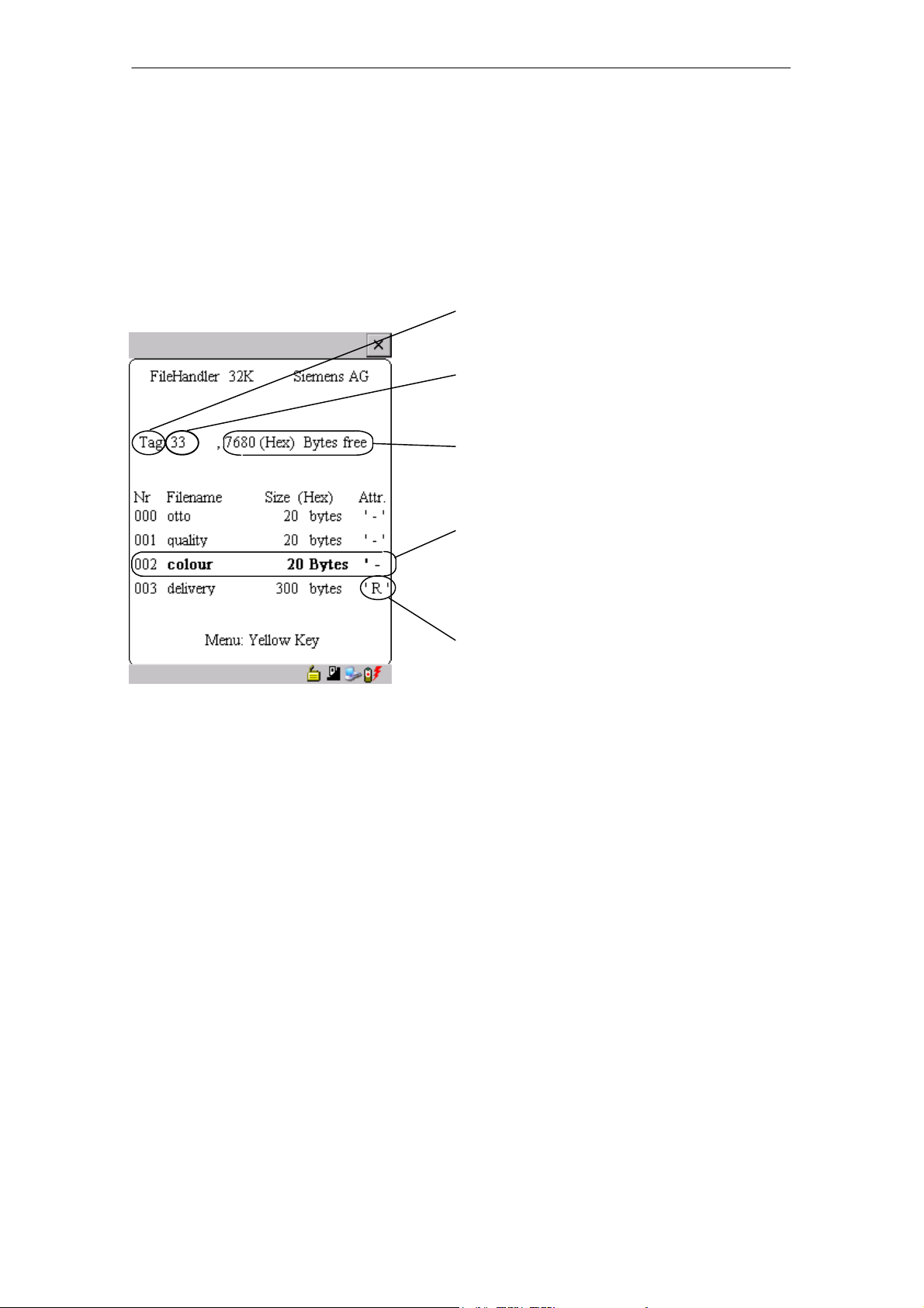
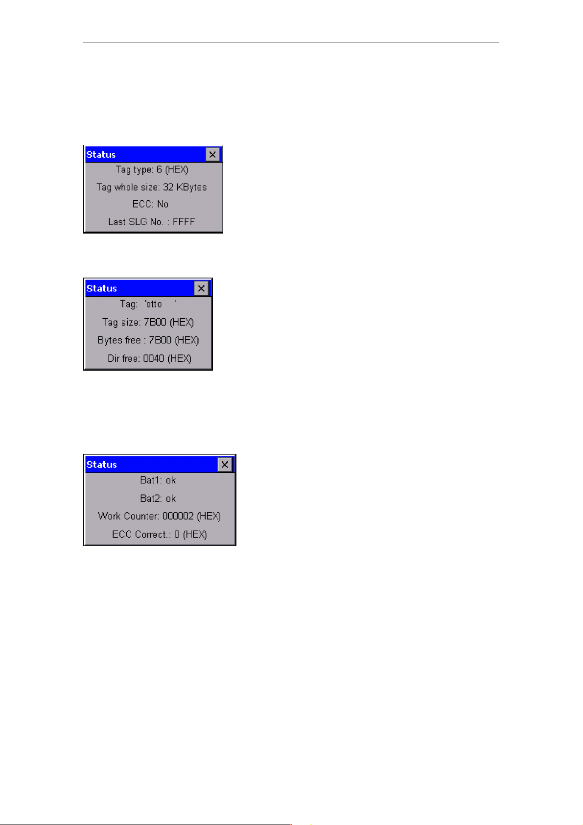
5.5.5 MDS Status (Tag Status)
This command shows the status of the MDS in several consecutive screens.
MDS type (Tag type)
This value is identical to the specification of the
MDS type with the Format command on a SIMATIC.
Gross MDS size (Tag whole size)
The size of the MDS which was set with the Format
command is indicated.
ECC
Indicates whether the MDS is used with or without
ECC
MDS (Tag)
Indicates the name of the MDS which was written to
the MDS with the Format command
MDS size (Tag size)
Indicates the maximum memory area which can be
used by the user
Bytes free
Indicates the number of data bytes on the MDS
which the user can still use for his/her data
Directory free (Dir free)
Indicates the number of files which can still be set
up on the MDS
Battery 1 (Bat1)
Status of the RAM battery. This value does not apply to the EEPROM MDS.
Battery 2 (Bat2)
Status of the dialog battery with MDS 507
Amount of processing (Work Counter)
Number of processing procedures which were performed with the MDS since it was initially formatted.
This value is particularly important for the EEPROM
MDS since the number of write-accesses is limited
for these types of memory.
STG Hand-Held Terminal PRO
(5)J31069-D0126-U001-A6-7418
ECC Correct
Counter for the number of ECC offsets performed.
If this counter has a value other than zero, the MDS
must be replaced in the near future. An EEPROM
memor
was write-accessed too often.
E-43
Page 50
The “FILEHANDLER” Program
R 05/07
5.5.6 MDS Cover
The Cover command protects the entire file structure on the MDS. If an MDS is
“covered”:
S Every file can be read.
S Every file can be written as long as the file length is not changed.
S No files can be deleted.
S No new files can be created.
S The format of the MDS can be initialized again. This “uncovers” the MDS.
S The “covered” state can be canceled with a Cover command and the setting
“not covered.”
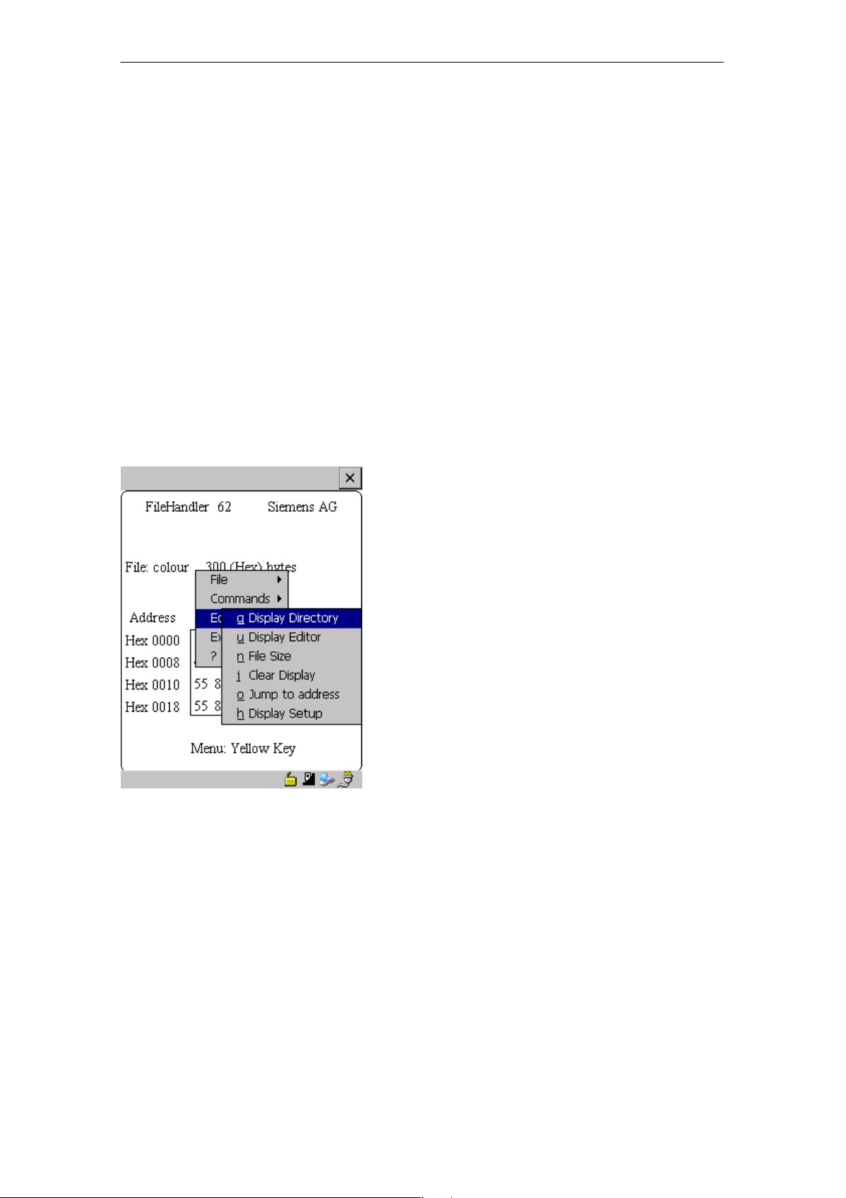
5.6 The Editor Menu
5.6.1 Display Directory
This function switches the display to the directory view (see chap. 5.3.2). The
directory which was read last is displayed. The directory can be from the MDS
or the hand-held terminal.
STG Hand-Held Terminal PRO
E-44
(5)J31069-D0126-U001-A6-7418
Page 51

R 05/07
The “FILEHANDLER” Program
5.6.2 Display Editor
This function switches the display to the editor view (see chap. 5.3.1). The display shows the file which was read last. This file can be from the MDS or the
hand-held terminal.
5.6.3 Change File Size (File Size)
The editor shows the current size of a file in the second line. This length can
be modified with the “File Size” command. When the file is made longer, an appropriate number of zeros (00 Hex) is appended to the end of the file. The editor shows the appended portion with inverted digits.
5.6.4 Delete Display (Clear Display)
This function clears the memory of the editor display. The hexadecimal value
of the filler character can be specified. The standard filler character is 00hex.
After deletion, all data in the display are shown inverted to indicate that no data
have been entered yet by the user.
5.6.5 Jump to Address
Normally the cursor is positioned within a file with the four cursor keys. With
large files, it is much quicker to use the “jump to address” function to position
the cursor anywhere within the file. You can also call the “jump to address”
function very easily with the Tab key.
5.6.6 Display Setup
The display is set here. You can choose either hexadecimal or ASCII format.
In ASCII format, the characters which cannot be shown appear as white fields.
STG Hand-Held Terminal PRO
(5)J31069-D0126-U001-A6-7418
E-45
Page 52
The “FILEHANDLER” Program
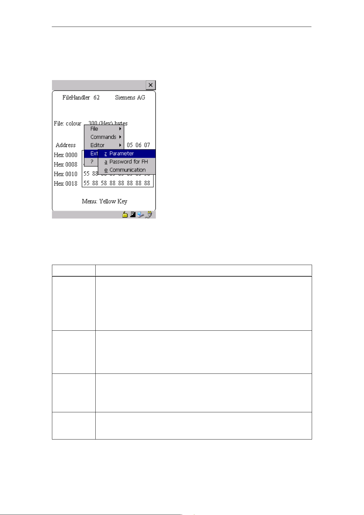
5.7 The Extras Menu
R 05/07
5.7.1 Parameter
The “parameter” function is used to make the basic settings for the filehandler.
Parameter Description
MDS size The gross memory size of the MDS is set here.
This memory size is shown in the first line of the display. The Format
command uses the memory size to specify the file system. If the
“MDS size” parameter does not correspond to the MDS being used,
the MDS can still be used. Only the Format command would produce
the wrong result.
MDS type Here you can switch between RAM, EEPROM and MDS 507. FRAM
memory is treated as RAM memory. If EEPROM is selected, the battery error message is suppressed on the display since these MDSs do
not have batteries. If MDS 507 is selected, the dialog battery is also
evaluated. When empty, this is shown on the display.
ECC
SLG no.
(hex)
Activate/deactivate ECC driver
When an MDS is processed, the SLG no. selected here is written to
the system area of the MDS. It has no effect on the function of the Filehandler program on the STG hand-held terminal PRO.
EAKO The entry/exit check cannot be set on the STG hand-held terminal
PRO with the filehandler. The STG hand-held terminal PRO does not
use entry/exit control (AEKO = 4).
STG Hand-Held Terminal PRO
E-46
(5)J31069-D0126-U001-A6-7418
Page 53

R 05/07
The “FILEHANDLER” Program
5.7.2 Password for Filehandler (Password for FH)
The filehandler password protects the STG hand-held terminal PRO data on
the MDS from being manipulated by unauthorized parties. The passwords for
the “Filehandler” and “MOBY D/E/I” programs are identical. See chapter 4.5.2
for a description of how to handle the password.
5.7.3 Communication
In principle, communication of the filehandler is always set to “read head.”
However, the filehandler can be changed to “ASM on RS 232” as an option. A
type “ASM420-RS232” module can then be connected to the hand-held terminal. For more information, see chapter 6.5.
Remember that a type “ASM 421” module cannot be used with the STG handheld terminal PRO.
5.8 The “?” Functions
These functions are the same as those of the “MOBY D/E/I” programs. See
chapter 4.6.
STG Hand-Held Terminal PRO
(5)J31069-D0126-U001-A6-7418
E-47
Page 54

Expanded Functions
R 05/07
6 Expanded Functions
6.1 Storing the MDS Data on the STG Hand-Held Terminal PRO
The data read from the MDS are automatically stored on the hand-held terminal
in a file named “READ_D.HEX,” “READ_E.HEX” or “READ_I.HEX” in the folder
/SIBO/M of the PSION Workabout PRO. Every additional read command overwrites this file.
When the MDS is write-accessed, the write data are written from the editor to
the MDS and also to the folder /SIBO/M on the PSION Workabout PRO under
the name “WRITE_D.HEX,” “WRITE_E.HEX” or “WRITE_I.HEX.” Every additional write command overwrites this file.
You can load a previously stored file into the editor using the “file/load file” function. To do this, enter the name of the file without the suffix “.HEX.”
You can also call up a list of the stored files by leaving the entry field blank and
pressing the ENTER key.
You can now select the corresponding file using the cursor keys.
The “file/save” function stores the data of the editor in a file with the file extension “.HEX” and at the same time the ID number in a file with the file suffix
“.HX1” in the folder /SIBO/M/HX on the PSION Workabout PRO. You can specify any name of 1 to 8 alphanumeric characters.
Note
When you read data from the MDS, modify data in the editor and
then save the data, the modified data will be stored in the .HEX file.
E-48
STG Hand-Held Terminal PRO
(5)J31069-D0126-U001-A6-7418
Page 55

R 05/07
Expanded Functions
6.2 Copying MOBY Data from and to the STG Hand-Held Terminal PRO
6.2.1 What Is Needed in Addition?
S Workabout PRO docking station (Order number see catalog)
S USB Driver for STG hand-held terminal PRO
Is included on CD “RFID Systems Software & Documentation” from product
version 07/2007 (Order number 6GT2080-2AA10)
S Active Sync program Version 3.4 or higher
Note
Download of Microsoft Active Sync
Microsoft Active Sync is not part of the scope of supply. However,
the current version of the application can be downloaded from
www.microsoft.com.
STG Hand-Held Terminal PRO
(5)J31069-D0126-U001-A6-7418
E-49
Page 56

Expanded Functions
R 05/07
6.2.2 Installing procedure
1. Install Microsoft Active Sync on the PC
2. Install a USB driver STG Hand-Held Terminal PRO on the PC
3. Establish a partnership between the PC and the STG Hand-Held Terminal
PRO
Install Microsoft Active Sync on the PC
With Microsoft Active Sync, you can synchronize files between your PC and the
STG Hand-Held Terminal PRO and transfer applications to the reader. With an
Active Sync connection, the MOBY Workabaout PRO can be accessed as a
drive in Windows Explorer under “Mobile Device”. For further information on
Microsoft Active Sync, see the accompanying help file.
If Microsoft Active Sync is not installed on your PC or if an earlier version than
3.4 is installed, you should install the current version available from Microsoft.
Notice
Update / Installation of Microsoft Active Sync
Before you update or install Microsoft Active Sync, you must
deinstall the old version.
Proceed as follows when installing Microsoft Active Sync:
1. Start the installation program by double-clicking the file msasync.exe.
2. Follow the instructions on the screen.
Note
Standard Sync Folder
When installation has been completed, Microsoft Active Sync
creates the folder Workabout Pro My Documents on the desktop of
your PC.
In the Active Sync settings menu under Sync Options, when you select the option Data, the content of the desktop folder is synchronized on the reader for every Active Sync procedure with the content
of the folder My Documents on the reader.
E-50
STG Hand-Held Terminal PRO
(5)J31069-D0126-U001-A6-7418
Page 57

R 05/07
Expanded Functions
Install a USB driver for STG Hand-Held Terminal PRO on the PC
Note
Windows XP: Ignore compatibility test
During installation of the USB driver under Windows XP, a message
may be displayed indicating that the driver has failed the compatibility test. Ignore this message and proceed with the installation.
Proceed as follows to install the USB driver for the STG Hand-Held Terminal
PRO:
1. Connect the STG Hand-Held Terminal PRO to a spare USB port of your PC
through the USB cradle.
2. Switch the STG Hand-Held Terminal PRO on.
3. Insert the CD RFID Systeme Software & Dokumentation in the drive of
your PC.
4. Start the installation program by double-clicking the file \daten\STG_PRO\
USB_Driver\usbsetup.exe.
5. Under Select Device, select the option Workabout Pro.
6. Follow the instructions on the screen.
Establish a partnership between the PC and the STG Hand-Held Terminal PRO
A relationship must be established between the PC and the reader so that
Microsoft Active Sync recognizes the STG Hand-Held Terminal PRO.
1. Proceed as follows to establish the partnership:
2. Connect the STG Hand-Held Terminal PRO to a spare USB port of your PC
through the USB cradle.
3. Switch the STG Hand-Held Terminal PRO on.
4. Microsoft Active Sync starts automatically and recognizes the reader as a
new device. Answer the prompt as to whether a partnership should be established between the PC and the reader with Yes.
5. Follow the instructions on the screen.
STG Hand-Held Terminal PRO
(5)J31069-D0126-U001-A6-7418
E-51
Page 58

Expanded Functions
R 05/07
6.2.3 Data exchange
Requirement:
A partnership is established between STG Hand-Held Terminal PRO and PC.
(see chapter 6.2.2).
STG Hand-Held Terminal PRO is seated in docking station and switched on.
In Windows Explorer you see a new Icon “Mobile Device”. With double clicking
you get the filesystem of your STG Hand-Held Terminal PRO.
Alternativly you could Open ActiveSync program and press “Explore” button, or
select menu “File/Explore”.
Open the file tree of STG Hand-Held Terminal PRO by double-clicking the SIBO
folder, and than the Folder M. There you will find, among others, the
“READ_D/E/I.HEX” file and the files which you stored with the extension
“.HEX.” Now drag and drop or copy these files from the STG Hand-Held Terminal PRO drive to the PC drive.
STG Hand-Held Terminal PRO
E-52
(5)J31069-D0126-U001-A6-7418
Page 59

R 05/07
Expanded Functions
The length of the READ or WRITE file is the same as that of the MDS which
was read.
READ_D.HEX: 44 bytes for I-Code1
112 bytes for I-Code SLI
256 bytes for Tag-it HF-I
992 bytes for my-d
READ_E.HEX: 768 bytes for MOBY E (in normal mode)
1024 bytes for MOBY E (after reading the raw data)
1024 bytes for MOBY E (in SIM mode)
READ_I.HEX:
Setup Setting No ECC With ECC
62 bytes
128 bytes
2 KB
8 KB
32 KB
62
128
2045
8189
32765
42
112
1778
7154
28658
The contents of the file can now be indicated and changed with an appropriate
editor on your PC.
When ASCII data were read from the MDS:
Any editor can be used (e.g., NOTEPAD, WRITE, WORD and so on).
When binary data were exchanged with the MDS:
Use a HEX editor. HEX editors are available on the shareware market
(e.g., Hedit and so on) or on the professional market (e.g., Codewright).
STG Hand-Held Terminal PRO
(5)J31069-D0126-U001-A6-7418
E-53
Page 60

Expanded Functions
R 05/07
6.2.4 Organization of the READ.HEX File
The READ_x.HEX file only contains the pure data which also exist on the MDS.
The length of the file is the same as that of the MDS, specified in bytes.
6.2.5 Organization of the READ.HX1 File
The READ_x.HX1 file contains the ID number. The READ_x.HX1 file is only
created for MOBY D/E.
6.3 Functions with the PSION Operating System
You can use the FILE/EXIT menu command to access the operating system
level of the hand-held terminal. We will now describe some of the functions
which are available with the Windows CE operating system.
Note
This functionality is only in Supervisor mode available see chapter 6.5.1.
S Setup and Configuration of STG Hand-Held Terminal PRO
S Edit the read MOBY data with the PSION editor. Remember that this editor
can only be used when the MDS data are in ASCII format.
S Spread sheet function
S Calculator
S Execution of commands
See the manual entitled “Psion Teklogix Workabout PRO Hand-Held Computer
User Manual” for a detailed description of operating system functions and standard programs. This manual can be ordered from PSION. See appendix A.1.
E-54
STG Hand-Held Terminal PRO
(5)J31069-D0126-U001-A6-7418
Page 61

R 05/07
Expanded Functions
6.4 Automatic Power Saver Function
The PSION Workabout PRO has an automatic power saver function. This is
activated after no keys have been pressed on the PSION Workabout PRO for
approximately 5 minutes.
In addition, the “MOBY D/E/I” programs have another power saver function.
The MDS command being executed is interrupted if no MDS is detected
30 seconds after the start of an MDS command or the MDS being processed is
moved out of the field for more than 30 seconds. The following message appears.
You can now completely terminate the
command with ESC or continue with
ENTER. If you decide to continue, the
interrupted command is continued at
the point at which it was interrupted.
STG Hand-Held Terminal PRO
(5)J31069-D0126-U001-A6-7418
E-55
Page 62

Expanded Functions
R 05/07
6.5 Connecting SIM Devices (MOBY E/I)
A MOBY E SIM can be connected to the RS 232 interface of the PSION Workabout PRO. The following figure shows the connection diagram. Before commissioning, a switch must be made to MOBY E/SIM or ASM 420/I with the
“EXTRAS/COMMUNICATION/PROTOCOL” function.
With this configuration, SIM can be used to work with the “MOBY” program and
user applications with the MOBY library. Cf. appendix A.2.
MOBY E/SIM:
Cable (6GT2391-1DH50)
and
Power pack (6GT2090-0HB00)
AC 220 V
DC 24 V
Note
Since the standard SIM of MOBY E uses cyclic operation, it takes
much, much longer to process a read/write command than with the
STG read head. The EXTRAS/MOBY E Setup/MODE command can
be used to switch the SIM to the faster read mode. This command
must be repeated each time SIM is turned on.
E-56
STG Hand-Held Terminal PRO
(5)J31069-D0126-U001-A6-7418
Page 63

R 05/07
Expanded Functions
ASM 420/I:
This settings permits an ASM 420/RS 232 to be connected to the hand-held
terminal. The connection cable must comply with the specifications in the
ASM 420 documentation. In ASM 420 mode, the MOBY V driver is always enabled during the “MOBY I” program. SLG 65 can be used on the ASM 420 with
this.
Use of MOBY I SLGs is limited.
Assignment of the RS 232 interface on the hand-held terminal:
Pin Designation
2 TxD
3 RxD
5 Gnd
STG Hand-Held Terminal PRO
(5)J31069-D0126-U001-A6-7418
E-57
Page 64

Expanded Functions
R 05/07
6.5.1 Security
The STG Hand-Held Terminal PRO has two security states:
S Supervisor
For configuration and setup of STG Hand-Held Terminal PRO.
Not necessary if MOBY Service and test application is used.
S User
Default state. User can only use preinstalled service and test application.
Start menu functionality is limited.
The security state could be changed via the security menu.
This menu is accessible via the windows start menu. The start menu itself is
started inside the MOBY service and test application with the key combination
“CTRL” + “ESC”.
Change to Supervisor is protected with password. At delivery password is set to
123456. Password should be changed at first use.
Notice
Be aware not to delete or manupilate files in folder “\Flash Disk”.
Files with extension “*.pfl” include the backup information of the delivery version. When you change into supervisor mode, please make
a backup of this file first and store it at a secure place. You could reset your STG Hand-Held Terminal PRO device to the delivery state,
if you copy your backupfile into folder “\Flash Disk” and performe a
system reset (see chapter 6.6).
Note
If the files with the endings “.PFL” are damaged or have got lost the
original state of the device can only be restored in the factory.
E-58
STG Hand-Held Terminal PRO
(5)J31069-D0126-U001-A6-7418
Page 65

R 05/07
Expanded Functions
6.6 System RESET
The hand-held terminal executes a system RESET when the device is turned
on for the first time after the batteries have been installed. This RESET is the
same as a hardware RESET.
A system RESET can also be triggered by hand. To do this, change STG
Hand-Held Terminal PRO in supervisor mode. See chapter 6.5.1. Than activate the function “Cold Reset” via start menu/Shutdown.
During the system RESET:
S Data stored in flash memory are always retained (“Flash Disk”).
S The data in RAM memory are lost.
Be aware that your password for supervisor mode is also reseted and has to be
initialized again.
STG Hand-Held Terminal PRO
(5)J31069-D0126-U001-A6-7418
E-59
Page 66

Error Messages
R 05/07
7 Error Messages
What to do when ...
... The PSION display goes blank during MOBY read/write.
S The batteries of the PSION Workabout PRO are empty. Insert device in
the charging shell, or install new batteries.
... The display remains blank after the device is turned on.
S The batteries are empty.
7.1 Error Messages with the “MOBY D/E/I” Programs
The messages in the following tables can occur during operation. The messages are indicated in a separate window. A message can have the following
format.
Type of error
Exact error designation
Type of Error Description
1 to 2 General errors
3 to 9 MOBY E errors
10 to 15 reserved
20 Timer errors
30 to 37 MOBY I errors
42 to 45
52 to 57
60 to 72 reserved
MOBY D errors
MOBY D ISO errors
The message is coded in several digits,
has the format is xx/yy/zz, and is used for
precise error analysis. The following tables
list the types of errors and the error designations in detail. The information in /zz is
included in some messages. “zz” contains
additional error information (e.g., the block
in which the error occurred).
E-60
STG Hand-Held Terminal PRO
(5)J31069-D0126-U001-A6-7418
Page 67

R 05/07
Error Designation Possible Causes and Their Correction
1, 2, 3, 4, 5, 6 S Reader device fails to send start protocol.
S Is read head screwed on?
S Does the read head match the protocol setting? (See
menu: Extras/COMMUNICATION.)
S Batteries in the reader device are dead. (The batteries may
be defective.)
S Internal program error
7 Interface defective
10, 11, 12 Reader device doesn’t answer at all or sends an incorrect an-
swer (MDS D1xx/MDS F4xx).
20 S Reader device doesn’t answer.
S Check parameters in the Extras/COMMUNICATION menu.
With SIM mode, “Interface” and
to SIM.
S Batteries in the reader device are empty. (The batteries
may be defective.)
“Protocol” must both be set
Error Messages
21 Reader device doesn’t answer at all or sends an incorrect
answer.
S Internal program error (MDS D1xx)
22 to 27 S Reader device sends the wrong answer.
S MDS is not personalized with the MOBY key.
S Internal program error (MDS D1xx/MDS F4xx)
32 Illegal request, internal program error
S Check contact to read head.
S Read device doesn’t answer (MDS E6xx)
33, 34, 35, 36 Internal program error
S Exit STG program, and start again.
S Read/write error (MDS F4xx)
37 S Read head gives you an error message.
S Read head is faulty.
S CRC error of MDS. Communication error to MDS. MDS is
located on the boundary.
S MDS has a defect.
S Internal program error
38 Specified block is write-protected.
39 Several MDSs are in the field.
S Internal program error (MDS D1xx)
STG Hand-Held Terminal PRO
(5)J31069-D0126-U001-A6-7418
E-61
Page 68

Error Messages
Error Designation Possible Causes and Their Correction
40, 41, 42 Reader device doesn’t answer at all or sends an incorrect an-
swer (MDS D1xx).
S Internal program error (MDS D1xx)
43 User termination with ESC
45 Wrong answer from read device
50 Error while reading or writing the MDS data
52, 53, 54, 55,
56, 57
63 Authentication error. The MDS doesn’t have the MOBY key.
65 Interface error. Appears when a SIM is connected.
Internal program error on MOBY read head
S Try setting the “B” key under “Extras/MOBY E Setup.”
S Check parameters in the “Extras/COMMUNICATION”
menu.
S Check plug and cable to SIM.
R 05/07
66 General read/write error on MOBY read head
67 Internal program error on MOBY read head
70 S Write not successful
S Several tags in the field
80 MDS type on reader device is not supported.
81, 82 S Read device sends wrong answer.
S MDS not personalized with MOBY key
101 to 132 Read device sent error (MOBY I).
Specification of certain errors:
101 Presence error
S No MDS in the field which has the MDS ID number con-
tained in the command.
103 Error in the connection to the SLG
S Read head hardware has a defect.
104 Error in MDS memory
S Execute INIT command. Before executing this command,
make sure that the memory size of the MDS is set correctly
under “Extras/MOBY I Setup.”
S The MDS is defective.
105 MOBY command cannot be interpreted by the read head.
S Check the memory size under “Extras/MOBY I Setup.”
106 S Field interference on read head. External interference.
S The MDS left the field during communication.
S Field interference during communication
STG Hand-Held Terminal PRO
E-62
(5)J31069-D0126-U001-A6-7418
Page 69

R 05/07
Error Designation Possible Causes and Their Correction
107 Too many sending errors. The MDS wasn’t able to correctly
receive the data from the read head.
S The MDS is located in the boundary area of the read head.
109 CRC error due to field interference while initializing the MDS
110 MDS cannot be initialized and is defective.
111 Timeout during initialization (MOBY I)
S The MDS is located in the boundary area of the read head.
S An MDS 507 is initialized but MDS 507 mode has not been
enabled under “Extras/MOBY I Setup.”
112 S The MDS memory cannot be written and is defective.
S The OTP memory cannot be written again.
113 The address area of the MDS was exceeded.
S Check the memory size under “Extras/MOBY I Setup.”
Error Messages
114 ECC error or MDS not initialized in ECC mode
S Enable ECC mode under “Extras/MOBY I Setup,” and then
execute the INIT command.
115 Reset message after return of power
S The hand-held terminal has a defect in the power supply to
the read head. (Try charging/replacing the batteries.)
S The hardware of the read head has a defect.
125 Internal program error. Previous command is active.
129 The number of MDSs in the field is not permitted. Number of
MDS > multitag in the “SLG Status” function under “Extras.”
130 Internal program error. The telegram layout of the command to
the read head is wrong.
180 to 243 Internal program error (MDS D1xx)
Turn the device off and on again. If error continues to occur,
contact Customer Support and specify the error number.
251 Read/write comparison not successful
255 No card/no MDS in the field
STG Hand-Held Terminal PRO
(5)J31069-D0126-U001-A6-7418
E-63
Page 70

Protocol
Error Messages
R 05/07
7.2 Error Messages with the “FILEHANDLER” Program
The following table lists the messages which can occur with the filehandler. A
filehandler error message looks like this.
The filehandler error is shown in the same
way as the filehandler on the SIMATIC. The
error message has one alpha character fol-
Type of error
(see chap. 7.1)
Exact filehandler error
lowed by a 3-position number. Most of the
error codes are identical with the error numbers of all MOBY filehandler interfaces.
Filehandler
Error
A006 Unknown command. Command identifier KK is illegal.
A011 With 1st command block: DBN not 1
A015 Checkbyte error while receiving from S5
A016 Command from other sender is being processed.
A020 Wrong number of characters in the telegram
B001 Error in the connection to the SLG
C002 Error on RAM of the MDS. Replace MDS and perform
C006 Presence error. MDS in boundary area.
C007 Parameterization error during FORMAT. Command
C008 Too many sync attempts. Field interference on read
C009 Too many sending errors
Description of Error, Its Cause and Correction Type of
With next block: KK or DBN incorrect
Read head defective
FORMAT.
cannot be interpreted.
head.
Error
errors
SLG errors
C010 CRC sending error
C011 FORMAT. CRC error while receiving.
C012 FORMAT. MDS cannot be initialized.
C013 FORMAT, timeout. MDS in boundary area.
C014 FORMAT, not initialized. Check Extras/Parameter.
C015 CMD address error. Check Extras/Parameter.
C016 ECC error. Format MDS again. Disable ECC mode.
C017 General driver error
STG Hand-Held Terminal PRO
E-64
(5)J31069-D0126-U001-A6-7418
MDS errors
Page 71

R 05/07
Job related
d
errors
Error
filehandler
pp
Error Messages
Filehandler
Error
D001 Only RESET command permitted
D005 Illegal parameters for FORMAT, CREATE, WRITE,
D009 RESET command parameter wrong
D014 CREATE and WRITE: The user data area of the MDS
D015 Only FORMAT command possible. MDS not identified.
D018 Start address in the command is outside the data area
D022 Directory and/or FAT. Modifying an MDS protected with
D023 COVER: MDS name wrong
E001 MDS type is wrong or doesn’t match the set mode
E002 CREATE command: No more directory entries free
E003 CREATE command: File already exists in the directory.
E005 READ or WRITE: A FAT block sequence error was de-
Description of Error, Its Cause and Correction
UPDATE or ATTRIB
is completely full.
(i.e., start address > file length).
COVER is illegal.
(ECC).
termined. The FAT is defective.
Type of
Error
Job-related
errors
Directoryrelate
errors
F001 The addressed file does not exist.
F005 WRITE/UPDATE/DELETE command for a file which is
protected with the appropriate attribute
H140 Serial interface error
H141 Wrong interface
H142 Faulty timer
H143 Interface error
H144 Start-protocol error
H145 Reset error, WRITE
H146 Reset error, READ, no STX
H147 Reset error, READ, timeout
H148 Reset error, READ, wrong response
H149 Start error, WRITE
H150 Start error, READ, no STX
H151 Start error, READ, timeout
H152 Start error, READ, wrong response
H153 Start error, WRITE, length too long
File-related
errors
Error
messages
of the
filehandler
application
STG Hand-Held Terminal PRO
(5)J31069-D0126-U001-A6-7418
E-65
Page 72

Technical Data
8 Technical Data
Hardware
Processor Intel XScale PXA
RAM memory 128 Mbytes of which approx. 40 Mbytes can be used as
desired
ROM memory 64 Mbytes for operating system and Flash Disk.
Approx. 40 Mbytes can be used as disired
Monitor screen Graphic LCD monitor screen with 240 x 320 pixels, color
Keyboard Alphanumeric
Touch Touchscreen finger operation
Sound Internal speaker
Power supply Lithium Ion rechargeable battery
High-speed chargeable, automatic switch-off
Operation time: ca. 20 hours
(Read head inactive, display not lighted)
8 hours
(Read head active)
Backup battery: 3 V lithium Ion rechargeable coin battery
R 05/07
Interfaces LIF interface (LIF = Low Insertion Force) for battery charging
and communication with PC
RS 232 and TTL interface for connection of a MOBY read
head
Software
Operating system Windows CE 4.2 with SIBO C Emulation
File management Windows compatible
Integrated
software
MOBY service and test program
E-66
STG Hand-Held Terminal PRO
(5)J31069-D0126-U001-A6-7418
Page 73

R 05/07
Technical Data
Technical Data Complete Device
Read Head
(incl. Batteries)
Dimensions 90 x 305 x 44 [mm] 90 x 64 x 35 [mm]
Weight Approx. 460 g Approx. 100 g
Temperature Operation: –10 °C to +50 °C
Storage: –25 °C to +60 °C (without batteries)
Relative humidity 5% to 90%, no condensation
Protection rating IP54 (protected against splashed water)
1
Shock resistance Max. falling height on concrete: 1,2 m
EMC EN 55022, EN 55024
1 With STG U hand-held terminal, only for complete device with PSION Workabout PRO
STG Hand-Held Terminal PRO
(5)J31069-D0126-U001-A6-7418
E-67
Page 74

Technical Data
RF read/write head
MOBY D 13.56 MHz (I-Code; Tag-it)
Max. read distance: 60mm with MDS D139
Labels based on I-Code in standard size
(approx. 85 x 55 mm):
Max. read distance: 75mm with I-Code1
Certifications: ETS 300 330
MOBY E 13.56 MHz (MIFARE)
Max. read distance: 30mm with MDS E611
R 05/07
25mm with MDS D160
30mm with MDS D124
100mm with I-Code SLI
100mm with Tag-it HF-I
100mm with my-d
18mm with MDS E600
8mm with MDS E624
4mm with MDS E623
3mm with MDS E623,
mounted in metal
Certifications: ETS 300 330 reg. no. G100213L
FCC ID: KR5MIS
MOBY I 1.81 MHz (data); 134 kHz (power)
MDS Type Max. Read Distance
401/402
404/514/413E
403
506
439E
507 with battery
507 without battery
Certifications: ETS 300 330 reg. no. TTI-P-G 128/96
FCC ID: KR5MIS-I
(in mm)
6
20
8
12
12
35
4
E-68
STG Hand-Held Terminal PRO
(5)J31069-D0126-U001-A6-7418
Page 75

R 05/07
Appendix
A Appendix
A.1 Ordering Components for Expanded
Functions
The expanded functions of the STG hand-held terminal PRO require components which are not available from Siemens A&D.
If you need these components for your MOBY application, please contact
PSION directly or its representative in your country. You will find addresses
and order lists from PSION on the Internet under www.psionteklogix.com.
The PSION representative in your country is also located under this Internet
address.
The following components are required for the STG application as options.
Ordering Designation Remarks
Active Sync Also available free of charge under
the Microsoft Internet address
User’s guide for PSION Workabout PRO Ask your PSION representative.
S High-speed charging devices
S PSION Workabout PRO with numeric keyboard
These components are not required for the STG application. They are only of
importance if you want to program your own identification application on the
hand-held terminal.
STG Hand-Held Terminal PRO
(5)J31069-D0126-U001-A6-7418
E-69
Page 76

Appendix
R 05/07
A.2 Porting User Applications
User Applications based on successor MOBY STG devices could be ported to
this devices.
Note
Development of complete new user applications are possible, but it
is not recommendable. New projects should wait for the next generation of this devices.
What Do I Need?
The C development package from PSION and the empedded Visual Studio
from Microsoft is required for user applications.
Package Comment Vendor Where to get?
USB Driver Necessary to re-
cognize STG
Hand-Held Terminal PRO on
PC at USB port
Active Sync Communication
between PC and
WinCE based
device.
PSION Teklogix
Mobile Device
SDK
Embedded
Visual C++ 4.0
SIBO_CandOP_
for_
WindowsCE_p5
Software development kit for
Workabout PRO
Development
Environement
(Compiler)
SIBO to Windows
CE Migration kit
PSION
Teklogix
Microsoft Internet:
PSION
Teklogix
Microsoft Microsoft
PSION
Teklogix
Internet:
www.psionteklogix.com
RFID Systems Software &
Documentation
www.microsoft.com/
downloads
Internet:
www.psionteklogix.com
Developer Resources
section of Teknet page
Internet:
www.psionteklogix.com
Developer Resources
section of Teknet page
1
E-70
STG Hand-Held Terminal PRO
(5)J31069-D0126-U001-A6-7418
Page 77

R 05/07
Package Where to get?VendorComment
Appendix
MOBY.LIB Interface to
MOBY RFID
SIEMENS RFID Systems Software &
Documentation
1
modules
1 Order number 6GT2080-2AA10
For detailed description and possible restrictions please refer to “SIBO to Windows CE Migration kit”.
The MOBY Library
A library for MOBY D, MOBY E and MOBY I is available. The library
(MOBY D/E/I) is included on CD “RFID Systems Software & Documentation”
from product version 07/2007 (order number 6GT2080-2AA10) . The C library
also includes a description of the interface commands.
Please note that the library is not identical with the previous version on the basis of Workabout MX.
The following table summarizes the implemented commands.
The MOBY D Library
Function Call Short Description
RF_ReadBlock Reads a block from the MDS
RF_WriteBlock Writes a block
RF_ReadTagId Selects the tag. Reads the TagId
RF_Status Determines the tag type
RF_Init Writes all user blocks
nMobyDOpen Opens an interface
vMobyDClose Closes the opened interface
STG Hand-Held Terminal PRO
(5)J31069-D0126-U001-A6-7418
E-71
Page 78

Appendix
R 05/07
The tables below provide a summary of implemented commands.
The MOBY E Library
Function Call Short Description Type of Command
CCT_READ_N_BLOCK Read card data (1 to n data
Standard
blocks, max. of 96 bytes)
CCT_WRITE_N_BLOCK Write card data (1 to n data
Standard
blocks, max. of 96 bytes)
CCT_WRITE_SIGNAL Address digital output, re-
Standard
served for switching the
antenna
CCT_OFF Turn off antenna field Standard
CCT_MODE Set field mode of the
Standard
antenna field
CCT_OPEN Open logical device Only for
SIM operation
via RS 232
CCT_CLOSE Close logical device Only for
SIM operation
via RS 232
CCT_SETKEY Parameterize read-card/
Optional
write-card interface
CCT_SET_KEY_TEMP Change temporary key Optional
CCT_GET_FIELD_STATE Scan current card indices Optional
CCT_RESET Reset read head Optional -
general command
Although the commands of the MOBY E library are the same as those of the
standard MOBY E library “CCTWAPI,” not all commands of “CCTWAPI” are
available on the hand-held terminal.
E-72
STG Hand-Held Terminal PRO
(5)J31069-D0126-U001-A6-7418
Page 79

R 05/07
Appendix
The MOBY I Library (normal addressing of MDS)
Function Call Short Description
moby_init Initializes an MDS with a filler character from ad-
dress 0 to the end address
moby_read Reads a data block from the MDS
moby_write Writes a data block to the MDS
moby_reset Sends a reset command with parameterization
to the read head
moby_status Sends a status command to the read head
nMobyIOpen Opens the interface and turns on the read head
vMobyIClose Closes the opened interface. The read head is
turned off.
nMobyIReadStartProtocol Reads the startup telegram from the read head
STG Hand-Held Terminal PRO
(5)J31069-D0126-U001-A6-7418
E-73
Page 80

Appendix
R 05/07
The MOBY I Library (filehandler addressing)
Function Call Short Description
wFhRead Reads a complete file from the MDS
wFhWrite Writes a file or appends data to a file
wFhMdsStatus Sends a status command to the MDS
wFhAttrib Sets a file attribute
wFhDelete Deletes a file from the MDS
wFhCreate Sets up a new file on the MDS
wFhFormat Formats an MDS
wFhDir Reads a directory from the MDS
wFhCover Protects the MDS file structure
wFhDirInfo Writes information from the “DIR” structure to the
“DirInfo” structure
nTagTypeFromTable Returns the MDS type from a table
lTagLenFromTable Returns the MDS size from a table
Fhreset Resets the filehandler
nFhOpenCom Opens the interface and turns on the read head
vFhCloseCom Closes the opened interface. The read head is
turned off.
E-74
STG Hand-Held Terminal PRO
(5)J31069-D0126-U001-A6-7418
Page 81

Inhaltsverzeichnis
MOBY
STG Hand-Held Terminal PRO
Bedienungsanleitung
Allgemeines
Die Inbetriebnahme des
STG Hand-Held Terminal PRO
Die Bedienung des
STG Hand-Held Terminal PRO
Die Programme
“MOBY D/E/I”
Das Programm
“FILEHANDLER”
Erweiterte Funktionen
1
2
3
4
5
6
Fehlermeldungen
Technische Daten
Anhang
7
8
A
(5)J31069-D0126-U001-A6-7418
erschienen im Mai 2007
Page 82
Sicherheitshinweise
Dieses Handbuch enthält Hinweise, die Sie zu Ihrer persönlichen Sicherheit sowie zur Vermeidung
von Sachschäden beachten müssen. Die Hinweise zu Ihrer persönlichen Sicherheit sind durch ein
Warndreieck hervorgehoben, Hinweise zu alleinigen Sachschäden stehen ohne Warndreieck. Je
nach Gefährdungsstufe werden die Warnhinweise in abnehmender Reihenfolge wie folgt dargestellt.
Gefahr
!
!
!
bedeutet, dass Tod oder schwere Körperverletzung eintreten wird, wenn die entsprechenden Vorsichtsmaßnahmen nicht getroffen werden.
Warnung
bedeutet, dass Tod oder schwere Körperverletzung eintreten kann, wenn die entsprechenden Vorsichtsmaßnahmen nicht getroffen werden.
Vorsicht
mit Warndreieck bedeutet, dass eine leichte Körperverletzung eintreten kann, wenn die entsprechenden Vorsichtsmaßnahmen nicht getroffen werden.
Vorsicht
ohne Warndreieck bedeutet, dass Sachschaden eintreten kann, wenn die entsprechenden Vorsichtsmaßnahmen nicht getroffen werden.
Achtung
bedeutet, dass ein unerwünschtes Ergebnis oder Zustand eintreten kann, wenn der entsprechende
Hinweis nicht beachtet wird.
Beim Auftreten mehrerer Gefährdungsstufen wird immer der Warnhinweis zur jeweils höchsten Stufe
verwendet. Wenn in einem Warnhinweis mit dem Warndreieck vor Personenschäden gewarnt wird,
dann kann im selben Warnhinweis zusätzlich eine Warnung vor Sachschäden angefügt sein.
Qualifiziertes Personal
Das zugehörige Gerät/System darf nur in Verbindung mit dieser Dokumentation eingerichtet und betrieben werden. Inbetriebsetzung und Betrieb eines Gerätes/Systems dürfen nur von qualifiziertem
Personal vorgenommen werden. Qualifiziertes Personal im Sinne der sicherheitstechnischen Hinweise dieser Dokumentation sind Personen, die die Berechtigung haben, Geräte, Systeme und
Stromkreise gemäß den Standards der Sicherheitstechnik in Betrieb zu nehmen, zu erden und zu
kennzeichnen.
Bestimmungsgemäßer Gebrauch
Beachten Sie Folgendes:
Warnung
!
Das Gerät darf nur für die im Katalog und in der technischen Beschreibung vorgesehenen Einsatzfälle und nur in Verbindung mit von Siemens empfohlenen bzw. zugelassenen Fremdgeräten und
-komponenten verwendet werden. Der einwandfreie und sichere Betrieb des Produktes setzt sachgemäßen Transport, sachgemäße Lagerung, Aufstellung und Montage sowie sorgfältige Bedienung
und Instandhaltung voraus.
Marken
Alle mit dem Schutzrechtsvermerk gekennzeichneten Bezeichnungen sind eingetragene Marken
der Siemens AG. Die übrigen Bezeichnungen in dieser Schrift können Marken sein, deren Benutzung durch Dritte für deren Zwecke die Rechte der Inhaber verletzen kann.
Haftungsausschluss
Wir haben den Inhalt der Druckschrift auf Übereinstimmung mit der beschriebenen Hard- und Software geprüft. Dennoch können Abweichungen nicht ausgeschlossen werden, so dass wir für die
vollständige Übereinstimmung keine Gewähr übernehmen. Die Angaben in dieser Druckschrift werden regelmäßig überprüft, notwendige Korrekturen sind in den nachfolgenden Auflagen enthalten.
Siemens AG
Automation and Drives
Postfach 48 48
90437 Nürnberg
DEUTSCHLAND
(5)J31069-D0126-U001-A6-7418
Ausgabe 05/07
Copyright E Siemens AG 1999, 2000, 2002, 2003, 2007
Änderungen vorbehalten
Page 83

A 05/07
Inhaltsverzeichnis
Inhaltsverzeichnis
1 Allgemeines D-1. . . . . . . . . . . . . . . . . . . . . . . . . . . . . . . . . . . . . . . . . . . . . . . .
1.1 Einsatzgebiete D-2. . . . . . . . . . . . . . . . . . . . . . . . . . . . . . . . . . . . . . . .
1.2 Produktbeschreibung D-2. . . . . . . . . . . . . . . . . . . . . . . . . . . . . . . . . .
2 Die Inbetriebnahme des STG Hand-Held Terminal PRO D-4. . . . . . . . .
2.1 Mitgelieferte Komponenten D-4. . . . . . . . . . . . . . . . . . . . . . . . . . . . .
2.2 Einschalten des Gerätes und Einstellen der Betriebsart D-5. . . .
2.3 MOBY-Applikationen D-6. . . . . . . . . . . . . . . . . . . . . . . . . . . . . . . . . . .
2.4 Bedienung D-6. . . . . . . . . . . . . . . . . . . . . . . . . . . . . . . . . . . . . . . . . . . .
3 Die Bedienung des STG Hand-Held Terminal PRO D-7. . . . . . . . . . . . .
3.1 Die Tastatur D-7. . . . . . . . . . . . . . . . . . . . . . . . . . . . . . . . . . . . . . . . . .
3.1.1 Die Umschalttasten D-8. . . . . . . . . . . . . . . . . . . . . . . . . . . . . . . . . . . .
3.1.2 Tastenfunktionen D-8. . . . . . . . . . . . . . . . . . . . . . . . . . . . . . . . . . . . . .
3.2 Die Antenne am Lesekopf und das Antennenfeld D-9. . . . . . . . . .
3.3 Die Ladefunktion D-11. . . . . . . . . . . . . . . . . . . . . . . . . . . . . . . . . . . . . .
4 Die Programme “MOBY D/E/I” D-12. . . . . . . . . . . . . . . . . . . . . . . . . . . . . . . .
4.1 Der Dateneditor D-14. . . . . . . . . . . . . . . . . . . . . . . . . . . . . . . . . . . . . . .
4.2 Die MDS-Funktionen D-17. . . . . . . . . . . . . . . . . . . . . . . . . . . . . . . . . . .
4.2.1 Allgemeines zu Lesen und Beschreiben eines MDS D-18. . . . . . . .
4.2.2 MDS lesen D-19. . . . . . . . . . . . . . . . . . . . . . . . . . . . . . . . . . . . . . . . . . .
4.2.3 MDS beschreiben D-19. . . . . . . . . . . . . . . . . . . . . . . . . . . . . . . . . . . . .
4.2.4 MDS löschen/Initialisieren D-19. . . . . . . . . . . . . . . . . . . . . . . . . . . . . .
4.2.5 Lesen der ID-Nummer D-19. . . . . . . . . . . . . . . . . . . . . . . . . . . . . . . . .
4.2.6 Rohdaten lesen D-20. . . . . . . . . . . . . . . . . . . . . . . . . . . . . . . . . . . . . . .
4.3 Die Datei-Funktionen D-21. . . . . . . . . . . . . . . . . . . . . . . . . . . . . . . . . .
4.3.1 Laden einer Datei D-21. . . . . . . . . . . . . . . . . . . . . . . . . . . . . . . . . . . . .
4.3.2 Speichern D-21. . . . . . . . . . . . . . . . . . . . . . . . . . . . . . . . . . . . . . . . . . . .
4.3.3 Beenden D-21. . . . . . . . . . . . . . . . . . . . . . . . . . . . . . . . . . . . . . . . . . . . .
4.4 Die Funktionen Editor D-22. . . . . . . . . . . . . . . . . . . . . . . . . . . . . . . . . .
4.4.1 Sprung zur Adresse D-22. . . . . . . . . . . . . . . . . . . . . . . . . . . . . . . . . . .
4.4.2 Anzeige D-22. . . . . . . . . . . . . . . . . . . . . . . . . . . . . . . . . . . . . . . . . . . . . .
4.4.3 Anzeige löschen D-23. . . . . . . . . . . . . . . . . . . . . . . . . . . . . . . . . . . . . .
4.4.4 Datum editieren D-23. . . . . . . . . . . . . . . . . . . . . . . . . . . . . . . . . . . . . . .
STG Hand-Held Terminal PRO
(5)J31069-D0126-U001-A6-7418
D-I
Page 84

Inhaltsverzeichnis
A 05/07
4.5 Die Funktionen Extras D-24. . . . . . . . . . . . . . . . . . . . . . . . . . . . . . . . .
4.5.1 Kommunikation D-24. . . . . . . . . . . . . . . . . . . . . . . . . . . . . . . . . . . . . . .
4.5.2 Passwort D-25. . . . . . . . . . . . . . . . . . . . . . . . . . . . . . . . . . . . . . . . . . . . .
4.5.3 Antenne D-25. . . . . . . . . . . . . . . . . . . . . . . . . . . . . . . . . . . . . . . . . . . . . .
4.5.4 Adressen Setup D-26. . . . . . . . . . . . . . . . . . . . . . . . . . . . . . . . . . . . . . .
4.5.5 MOBY I Setup D-27. . . . . . . . . . . . . . . . . . . . . . . . . . . . . . . . . . . . . . . .
4.5.6 MOBY E Setup D-27. . . . . . . . . . . . . . . . . . . . . . . . . . . . . . . . . . . . . . . .
4.6 Die Funktionen “?” D-28. . . . . . . . . . . . . . . . . . . . . . . . . . . . . . . . . . . . .
4.6.1 Sprache D-28. . . . . . . . . . . . . . . . . . . . . . . . . . . . . . . . . . . . . . . . . . . . . .
4.6.2 Ueber D-28. . . . . . . . . . . . . . . . . . . . . . . . . . . . . . . . . . . . . . . . . . . . . . . .
4.6.3 Version D-28. . . . . . . . . . . . . . . . . . . . . . . . . . . . . . . . . . . . . . . . . . . . . . .
5 Das Programm “FILEHANDLER” D-29. . . . . . . . . . . . . . . . . . . . . . . . . . . . .
5.1 Allgemeines zum Filehandler D-29. . . . . . . . . . . . . . . . . . . . . . . . . . .
5.2 Die Filehandler-Befehle D-30. . . . . . . . . . . . . . . . . . . . . . . . . . . . . . . .
5.3 Die Anzeigen Editor und Directory D-32. . . . . . . . . . . . . . . . . . . . . . .
5.3.1 Der Dateneditor im Filehandler D-32. . . . . . . . . . . . . . . . . . . . . . . . . .
5.3.2 Die Directory-Ansicht D-33. . . . . . . . . . . . . . . . . . . . . . . . . . . . . . . . . .
5.4 Das Datei-Menü D-34. . . . . . . . . . . . . . . . . . . . . . . . . . . . . . . . . . . . . . .
5.4.1 Lese Datei vom MDS D-35. . . . . . . . . . . . . . . . . . . . . . . . . . . . . . . . . .
5.4.2 Lese Datei vom STG RAM D-35. . . . . . . . . . . . . . . . . . . . . . . . . . . . . .
5.4.3 Schreibe Datei auf MDS D-36. . . . . . . . . . . . . . . . . . . . . . . . . . . . . . . .
5.4.4 Schreibe Datei auf STG RAM D-37. . . . . . . . . . . . . . . . . . . . . . . . . . .
5.4.5 Lese Verzeichnis vom MDS D-37. . . . . . . . . . . . . . . . . . . . . . . . . . . . .
5.4.6 Lese Verzeichnis vom STG RAM D-37. . . . . . . . . . . . . . . . . . . . . . . .
5.4.7 Beispiel: Kopieren von Dateien D-38. . . . . . . . . . . . . . . . . . . . . . . . . .
5.5 Das Befehle-Menü D-40. . . . . . . . . . . . . . . . . . . . . . . . . . . . . . . . . . . . .
5.5.1 Datei neu D-40. . . . . . . . . . . . . . . . . . . . . . . . . . . . . . . . . . . . . . . . . . . . .
5.5.2 Datei löschen D-40. . . . . . . . . . . . . . . . . . . . . . . . . . . . . . . . . . . . . . . . .
5.5.3 MDS formatieren D-40. . . . . . . . . . . . . . . . . . . . . . . . . . . . . . . . . . . . . .
5.5.4 Datei Attribut D-41. . . . . . . . . . . . . . . . . . . . . . . . . . . . . . . . . . . . . . . . . .
5.5.5 MDS Status D-42. . . . . . . . . . . . . . . . . . . . . . . . . . . . . . . . . . . . . . . . . . .
5.5.6 MDS Cover D-43. . . . . . . . . . . . . . . . . . . . . . . . . . . . . . . . . . . . . . . . . . .
5.6 Das Editor-Menü D-43. . . . . . . . . . . . . . . . . . . . . . . . . . . . . . . . . . . . . .
5.6.1 Anzeige Verzeichnis D-43. . . . . . . . . . . . . . . . . . . . . . . . . . . . . . . . . . .
5.6.2 Anzeige Editor D-44. . . . . . . . . . . . . . . . . . . . . . . . . . . . . . . . . . . . . . . .
5.6.3 Datei Größe verändern D-44. . . . . . . . . . . . . . . . . . . . . . . . . . . . . . . . .
5.6.4 Anzeige löschen D-44. . . . . . . . . . . . . . . . . . . . . . . . . . . . . . . . . . . . . .
5.6.5 Sprung an Adresse D-44. . . . . . . . . . . . . . . . . . . . . . . . . . . . . . . . . . . .
5.6.6 Anzeige Setup D-44. . . . . . . . . . . . . . . . . . . . . . . . . . . . . . . . . . . . . . . .
D-II
STG Hand-Held Terminal PRO
(5)J31069-D0126-U001-A6-7418
Page 85

A 05/07
Inhaltsverzeichnis
5.7 Das Extra-Menü D-45. . . . . . . . . . . . . . . . . . . . . . . . . . . . . . . . . . . . . . .
5.7.1 Parameter D-45. . . . . . . . . . . . . . . . . . . . . . . . . . . . . . . . . . . . . . . . . . . .
5.7.2 Passwort für Filehandler D-46. . . . . . . . . . . . . . . . . . . . . . . . . . . . . . . .
5.7.3 Kommunikation D-46. . . . . . . . . . . . . . . . . . . . . . . . . . . . . . . . . . . . . . .
5.8 Die Funktionen “?” D-46. . . . . . . . . . . . . . . . . . . . . . . . . . . . . . . . . . . . .
6 Erweiterte Funktionen D-47. . . . . . . . . . . . . . . . . . . . . . . . . . . . . . . . . . . . . . .
6.1 Die Hinterlegung der MDS-Daten im Handterminal D-47. . . . . . . . .
6.2 Kopieren von MOBY-Daten von und zum
STG Hand-Held Terminal PRO D-48. . . . . . . . . . . . . . . . . . . . . . . . . .
6.2.1 Was wird zusätzlich benötigt? D-48. . . . . . . . . . . . . . . . . . . . . . . . . . .
6.2.2 Installation D-49. . . . . . . . . . . . . . . . . . . . . . . . . . . . . . . . . . . . . . . . . . . .
6.2.3 Daten Austausch D-51. . . . . . . . . . . . . . . . . . . . . . . . . . . . . . . . . . . . . .
6.2.4 Die Organisation der Datei READ.HEX D-53. . . . . . . . . . . . . . . . . . .
6.2.5 Die Organisation der Datei READ.HX1 D-53. . . . . . . . . . . . . . . . . . .
6.3 Funktionen mit dem PSION-Betriebssystem D-53. . . . . . . . . . . . . .
6.4 Die automatische Stromsparfunktion D-54. . . . . . . . . . . . . . . . . . . . .
6.5 Anschluss von SIM-Geräten (MOBY E/I) D-55. . . . . . . . . . . . . . . . .
6.5.1 Sicherheit D-57. . . . . . . . . . . . . . . . . . . . . . . . . . . . . . . . . . . . . . . . . . . .
6.6 System-RESET D-58. . . . . . . . . . . . . . . . . . . . . . . . . . . . . . . . . . . . . . .
7 Fehlermeldungen D-59. . . . . . . . . . . . . . . . . . . . . . . . . . . . . . . . . . . . . . . . . . .
7.1 Fehlermeldungen bei den Programmen “MOBY D/E/I” D-59. . . . .
7.2 Fehlermeldungen beim Programm “FILEHANDLER” D-63. . . . . . .
8 Technische Daten D-65. . . . . . . . . . . . . . . . . . . . . . . . . . . . . . . . . . . . . . . . . . .
A Anhang D-68. . . . . . . . . . . . . . . . . . . . . . . . . . . . . . . . . . . . . . . . . . . . . . . . . . . . .
A.1 Bestellung von Komponenten für erweiterte Funktionen D-68. . . .
A.2 Portieren von Anwenderapplikationen D-69. . . . . . . . . . . . . . . . . . . .
STG Hand-Held Terminal PRO
(5)J31069-D0126-U001-A6-7418
D-III
Page 86

Inhaltsverzeichnis
A 05/07
D-IV
STG Hand-Held Terminal PRO
(5)J31069-D0126-U001-A6-7418
Page 87
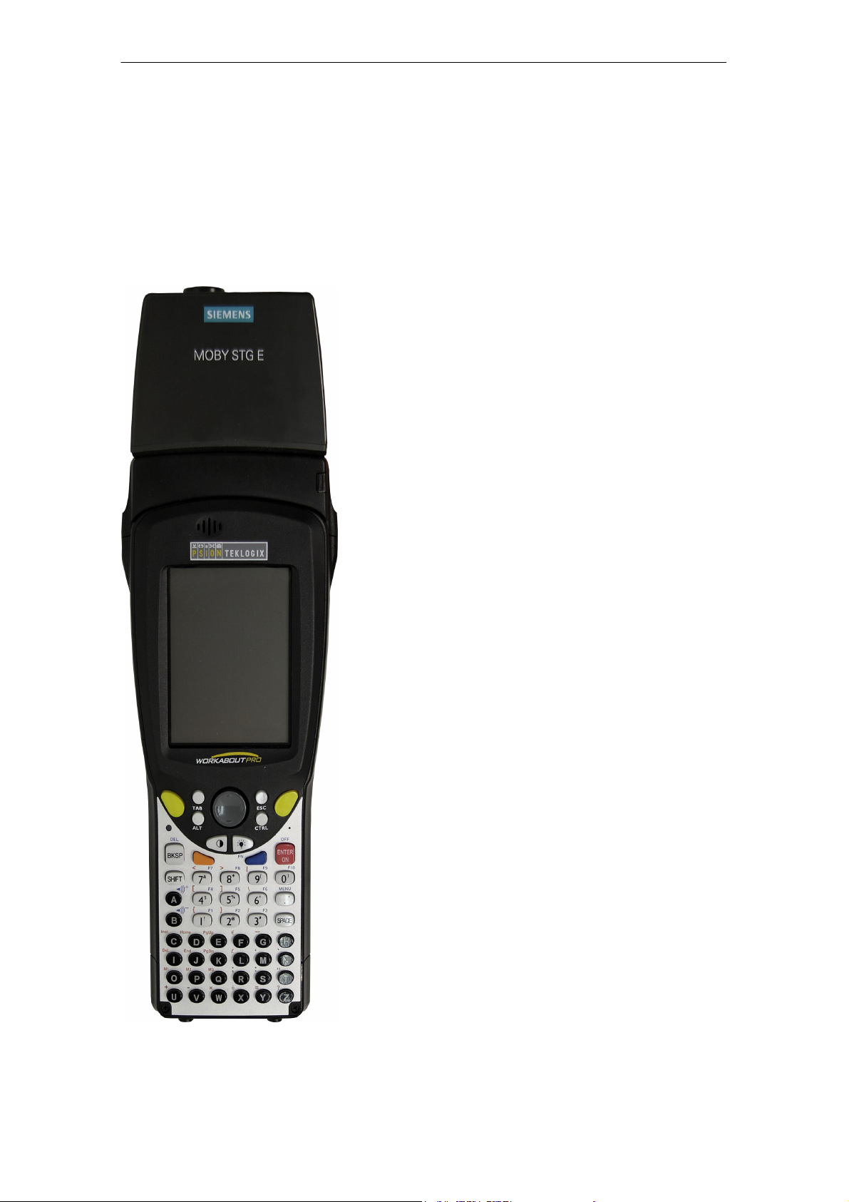
A 05/07
Allgemeines
1 Allgemeines
Das STG Hand-Held Terminal PRO (Service- und Testgerät) erweitert die Identifikationssysteme MOBY D, MOBY E bzw. MOBY I um ein leistungsfähiges mobiles Handterminal (Basis: PSION Workabout PRO) für Applikationen in den
Bereichen Logistik, Distribution und Service. Darüber hinaus ist es ein unentbehrliches Hilfsmittel bei der Inbetriebnahme und beim Test.
STG Hand-Held Terminal PRO mit
MOBY D/E/I Lesekopf
STG Hand-Held Terminal PRO
(5)J31069-D0126-U001-A6-7418
D-1
Page 88

Allgemeines
A 05/07
1.1 Einsatzgebiete
Das STG Hand-Held Terminal PRO ist bei MOBY D, MOBY E und MOBY I einsetzbar. Das enthaltene Service- und Testprogramm gestattet ein einfaches Lesen und Beschreiben aller Datenspeicher von MOBY D, MOBY E oder MOBY I.
Darüberhinaus kann der Kunde sehr einfach seine eigene Applikation auf dem
Handterminal programmieren. Eine C-Library für die Programmierung der
Handterminal-Leseköpfe wird von Siemens angeboten. Damit werden Anwendungen im Bereich Lager, Logistik und Kommissionierung einfach realisierbar.
Der Einsatz des Handterminals kann auch in rauher Umgebung erfolgen. Das
Handterminal ist sehr robust und gegen Spritzwasser geschützt. Das Display ist
durch die vorhandene Displaybeleuchtung gut lesbar.
1.2 Produktbeschreibung
Das STG Hand-Held Terminal PRO besteht aus einem Grundgerät und einem
Lesekopf von MOBY D, MOBY E oder MOBY I. Das Grundgerät ist ein PSION
Workabout PRO. Dieses Gerät ist weltweiter Standard bei industriellen Handterminals. Das Service- und Testprogramm startet sich beim Einschalten des
Handterminal automatisch. Mit dem Handterminal können alle Datenspeicher
von MOBY D, MOBY E oder MOBY I bearbeitet werden.
D-2
STG Hand-Held Terminal PRO
(5)J31069-D0126-U001-A6-7418
Page 89

A 05/07
Allgemeines
Folgende Funktionen können ausgeführt werden:
S Auslesen der Daten aus dem MDS
S Schreiben der Daten in den MDS
S Löschen des gesamten Datenspeichers (Beschreiben mit einem Füllwert)
S Lesen und Anzeigen der ID-Nummer des MDS (MOBY D/E)
S Darstellen und Editieren der Daten in Hexadezimal und ASCII
S Passwortschutz ein- und ausschaltbar für alle schreibenden Funktionen und
zum Beenden des MOBY-Programms
S Menüführung in verschiedenen Sprachen (Deutsch und Englisch)
S Abspeichern der gelesenen MOBY-Daten in Dateien. Dafür stehen im Hand-
terminal ca. 40 MB zur Verfügung.
Zusätzliche Funktionen bei MOBY I-Filehandler:
S Formatieren des MDS
S Anlegen von Dateien auf dem MDS
S Beschreiben von Dateien auf dem MDS
S Lesen von Dateien auf dem MDS
S Auslesen und Anzeigen der Directory
S Löschen von Dateien auf dem MDS
Der Schreib-/Lesekopf von MOBY D/E/I wird einfach mit dem PSION-Grundgerät verschraubt. Er besitzt eine serielle TTL-Schnittstelle für die Kommunikation
mit dem Grundgerät. Die Spannungsversorgung des Lesekopfes liefert das
Grundgerät.
Der Schreib-/Lesekopf oder die Antenne und das STG-Programm können auch
einzeln bestellt werden. Damit ist es möglich, dass der Kunde ein bereits vorhandenes PSION Workabout PRO verwendet.
Das entsprechende Ladegerät (inkl. 110-240-V-Steckernetzteil) für das Wiederaufladen der Akkus muss gesondert bestellt werden.
S MOBY D/E/I
Das Ladegerät (Bestellnummer siehe Katalog) als Docking Station ausgeführt.
Für kundenspezifische RFID-Applikationen steht dem Anwender eine C-Library
mit den Funktionen des MOBY-Lesekopfes zur Verfügung. Mit der optionalen
C-Entwicklungsumgebung für den PSION Workabout PRO kann der Anwender
eigene Programme entwickeln (vgl. Anhang A.2).
STG Hand-Held Terminal PRO
(5)J31069-D0126-U001-A6-7418
D-3
Page 90

Die Inbetriebnahme des STG Hand-Held Terminal PRO
A 05/07
2 Die Inbetriebnahme des STG Hand-Held
Terminal PRO
2.1 Mitgelieferte Komponenten
Die Lieferung des STG Hand-Held Terminal PRO besteht aus mehreren Komponenten. Diese sind auch einzeln im Lieferschein vermerkt:
Bestellte
Komponente
MOBY D
STG HandHeld Terminal
PRO
MOBY E
STG HandHeld Terminal
PRO
MOBY I
STG HandHeld Terminal
PRO
1 Die MOBY-Applikation ist auf dem STG Hand-Held Terminal PRO vorinstalliert.
Bestellnummer
6GT2603-0AA10 PSION Workabout PRO
MOBY D-Lesekopf 6GT2603-1AA00
6GT2303-0AA10 PSION Workabout PRO
MOBY E-Lesekopf 6GT2303-1AA00
6GT2003-0CA10 PSION Workabout PRO
MOBY I-Lesekopf 6GT2003-1CA00
Packliste
1
1
1
Packnummer
D-4
STG Hand-Held Terminal PRO
(5)J31069-D0126-U001-A6-7418
Page 91

A 05/07
Die Inbetriebnahme des STG Hand-Held Terminal PRO
2.2 Einschalten des Gerätes und Einstellen der Betriebsart
Nach dem ersten Aufladen des Akkus ist das Handterminal sofort betriebsbereit.
Schalten Sie das Gerät ein, in dem Sie ENTER/ON für 4 Sekunden gedrückt
halten. Es erscheint ein Auswahlmenü mit den MOBY-Applikationen für den
RF-Schreib-/Lesekopf, den Sie betreiben möchten.
MOBY D Service- und Testprogramm
MOBY E Service- und Testprogramm
MOBY I Service- und Testprogramm
MOBY I Service- und Testprogramm
(Die MDS-Daten sind über den Dateinamen verfügbar. Siehe Kapitel 5)
Das Gerät schaltet sich automatisch ab, nachdem für 5 Minuten keine Taste
gedrückt wurde. Wird das Gerät durch Drücken der ENTER/ON-Taste (für
ca. 4 Sekunden) wieder eingeschaltet, arbeitet das Handterminal mit der gleichen Maske weiter, in der es sich befand, bevor es manuell oder automatisch
abgeschaltet wurde (siehe Kap. 6.4).
Per Bedienung wird das Gerät durch aufeinanderfolgendes Drücken der Tasten
FN und ENTER/ON ausgeschaltet.
STG Hand-Held Terminal PRO
(5)J31069-D0126-U001-A6-7418
D-5
Page 92

Die Inbetriebnahme des STG Hand-Held Terminal PRO
A 05/07
2.3 MOBY-Applikationen
Sollten Sie zu einem späteren Zeitpunkt einen anderen Lesekopf (MOBY D/E/I)
am Handterminal betreiben, so müssen Sie zuerst die MOBY-Applikation umstellen. Hierzu müssen Sie die laufende Applikation über das Menü “Datei/Beenden” beenden. Es erscheint der PSION Arbeitsplatz, auf dem dann die benötigte MOBY-Applikation ausgewählt werden muss.
2.4 Bedienung
Die Bedienung der STG-Programme MOBY D/E/I ist im Kapitel 4 beschrieben.
Die Bedienung des Programmes Filehandler für MOBY I ist im Kapitel 5 be-
schrieben.
Über die gelbe Menü-Taste sind alle Funktionen der MOBY-Programme aufruf-
bar.
D-6
STG Hand-Held Terminal PRO
(5)J31069-D0126-U001-A6-7418
Page 93

A 05/07
Die Bedienung des STG Hand-Held Terminal PRO
3 Die Bedienung des STG Hand-Held Termi-
nal PRO
3.1 Die Tastatur
Die Tastatur des PSION Workabout PRO ist in 3 Teile gegliedert:
S Steuertasten direkt unterhalb des Displays
S numerischer Ziffernblock
S ASCII-Tastatur
Die grüne
Leuchtdiode
blinkt grün,
wenn der Akku
geladen wird
und leuchtet
dauerhaft,
wenn der
Ladevorgang
abgeschlossen
ist.
Steuertasten:
Ein-/Aus;
Cursortasten,
CTRL-Taste
Numerischer
Ziffernblock
ASCIITastatur
Gelbe Tasten: Öffnen des Menüs der MOBY-Applikation
STG Hand-Held Terminal PRO
(5)J31069-D0126-U001-A6-7418
D-7
Page 94

Die Bedienung des STG Hand-Held Terminal PRO
A 05/07
3.1.1 Die Umschalttasten
<SHIFT>
<CTRL>
<ALT>
<ORANGE>
<BLUE>
Aktivieren der Umschalttasten
Durch Drücken/Aktivieren einer Umschalttaste erscheint in der Taskleiste in
Kleinbuchstaben die Benennung der gewählten Umschalttaste, z. B. “org key”,
“blue key”. Eine nachfolgend aktivierte Taste ändert daraufhin ihre Funktion, die
Anzeige in der Taskleiste erlischt und die Umschalttaste ist wieder deaktiviert.
3.1.2 Tastenfunktionen
Taste Funktion
<SHIFT> Anzeige von Großbuchstaben (A-Z) und Symbolen,
die auf den Zifferntasten mit angegeben sind
(z. B. &, *,...).
Pfeiltasten
(graue runde Taste unterhalb des Displays)
<BKSP> Bewegt den Cursor nach links zum Löschen des
<DEL>
(blaue Taste und BKSP>
<CTRL>
<ALT>
<TAB> Bewegt den Cursor in bestimmten Abständen nach
<ESC> Schließen des momentan geöffneten Menüs, Dia-
Ermöglichen die Navigation im Display nach links,
rechts, oben und unten.
zuletzt eingegebenen Zeichens.
Entfernt das Zeichen, das nach dem Cursor steht.
Verändert die Funktion von anderen Tasten
rechts oder unten.
(<ORANGE> und <TAB> bewegt den Cursor zurück.)
logfensters oder einer gerade gestarteten Anwendung und Rückkehr zur vorherigen Oberfläche.
<SPACE> Einfügen von Leerzeichen.
In einem Windows-Dialogfenster können mit der
<SPACE>-Taste Kontrollkästchen aktiviert oder deaktiviert werden.
STG Hand-Held Terminal PRO
D-8
(5)J31069-D0126-U001-A6-7418
Page 95

A 05/07
Die Bedienung des STG Hand-Held Terminal PRO
3.2 Die Antenne am Lesekopf und das Antennenfeld
Die Antenne des Lesekopfes ist an der oberen Seite des Handterminals angeordnet.
Mit unterschiedlichen MDS-Typen werden unterschiedliche Reichweiten erzielt.
Die folgende Tabelle gibt einen Überblick:
MOBY D MOBY E MOBY I
MDS-Typ mm MDS-Typ mm MDS-Typ mm
D139 60 E600 (ISO-Card) 18 402/401 6
D160 25 E611 30 404/514/413E 20
D124 30
Labels auf Basis
I-Code:
3
E624 (Knopf) 8 403 8
E623 (Pille)
1
4/32506 12
I-Code1 75 439E 12
I-Code SLI 100 507 (mit Batterie) 35
Tag-it HF-I 100
my-d 100 507 (ohne Batterie) 4
1 Die Pille kann nur an dem hierfür vorgesehenen Kopfteil gelesen werden.
2 wenn MDS in Metall eingebaut ist
3 Fertigungsbedingt ist mit Reichweitentoleranzen zu rechnen. Die Reichweiten gelten
für Labels der Größe 85 x 55 mm.
STG Hand-Held Terminal PRO
(5)J31069-D0126-U001-A6-7418
D-9
Page 96

Die Bedienung des STG Hand-Held Terminal PRO
MOBY D/E MOBY E/I
A 05/07
Knopfantenne bzw.
Stabantenne (MOBY I)
z. B.:
MDS E600
Flächenantenne
z. B.:
MDS E623
Das Antennenfeld beim STG-Lesekopf
Das Antennenfeld bei MOBY E
Beim MOBY E-Lesekopf sind 2 Antennen im Leser integriert. Je nachdem, welchen MDS Sie lesen möchten, müssen Sie diesen entsprechend am Lesekopf
positionieren. Die Umschaltung des Antennenfeldes geschieht mit dem Befehl
Extras/ANTENNE (siehe Kap. 4.5.3). Wichtig ist dabei, dass der MDS E623 nur
an der hierfür vorgesehenen Antenne (siehe Bild) gelesen werden kann. Der
MDS E624 kann sowohl an der Knopfantenne als auch an der Flächenantenne
gelesen werden.
D-10
STG Hand-Held Terminal PRO
(5)J31069-D0126-U001-A6-7418
Page 97

A 05/07
Die Bedienung des STG Hand-Held Terminal PRO
3.3 Die Ladefunktion
Sobald Sie das PSION Workabout PRO in die Docking Station stecken, wird
der Ladevorgang der Akkus gestartet. Das Laden wird aktiviert und an einer
grünen Leuchtdiode angezeigt (siehe Kap. 3.1).
Bei leeren Akkus dauert eine komplette Ladung ca. 4 Stunden.
WICHTIG: Dem Gerät liegt eine Dokumentation “Quick Start Guide” bei. Die
darin enthaltenen Hinweise sind unbedingt zu beachten. Ebenso die entsprechenden Hinweise im PSION-Benutzerhandbuch bzw. der Dokumentation der
Docking Station.
Die Backup-Batterie
Die Backup-Batterie im PSION Workabout PRO dient zum Erhalt der Anwendungsdaten, wenn die Hauptbatterien entladen sind. Die Backup-Batterie ist
eine Lithiumzelle. Bitte beachten Sie, dass eine neue Backup-Batterie (bei entleerter oder entfernter Hauptbatterie) die Daten im RAM nur wenige Minuten
erhalten kann.
Die MOBY-Applikation ist ausfallsicher im Flash Speicher hinterlegt und ist daher auch nach einem Batterieausfall vorhanden. Falls die MOBY-Applikation
gelöscht oder beschädigt wurde, muss das Gerät zur Reparatur eingesandt
werden.
STG Hand-Held Terminal PRO
(5)J31069-D0126-U001-A6-7418
D-11
Page 98

Die Programme “MOBY D/E/I”
A 05/07
4 Die Programme “MOBY D/E/I”
Nach dem Einschalten des STG Hand-Held Terminal PRO erscheint am Display der Editor. Sie können nun die Daten anschauen, neue Daten eingeben
oder über die gelbe Menü-Taste eine Funktion aufrufen. Ein direkter Aufruf der
Funktionen ist über die Taste ebenfalls möglich. Drücken Sie hierzu nacheinander die Taste ALT und danach die entsprechende alphanumerische Taste. Die
folgende Tabelle zeigt alle Funktionen und die dazugehörigen Kurzaufrufe:
Befehl Kurzaufruf
Datei/Laden Datei D Datei vom PSION RAM-Laufwerk in den
Datei/Speichern C Gelesene MDS-Daten auf das
Datei/Beenden X STG-Anwendung beenden
MDS/Lesen L Daten vom MDS lesen
MDS/Schreiben S Daten auf MDS schreiben
MDS/Loeschen/Init E MDS mit bestimmten Wert beschreiben
MDS/Lese TagId T ID-Nummer des MDS lesen
MDS/Roh-Daten lesen R Physikalischen Speicher des MDS ausle-
Editor/Sprung zur Adresse J bzw. Tab Im Editor zu einer bestimmten Adresse
Editor/Anzeige O Optionen der Anzeige ändern
Editor/Anzeige loeschen F Daten im Editor auf bestimmten Wert
Editor/Datum editieren A Das Datum an der Cursorposition in ver-
Extras/Kommunikation K Optionen in der Kommunikation ändern
1
Arbeitsspeicher laden
RAM-Laufwerk speichern
sen
springen
löschen
schiedenen Formaten bearbeiten
Beschreibung
Extras/Passwort für STG P Passwort für die STG-Anwendung
ändern
Extras/Adressen Setup G Eingaben für die Befehle “MDS lesen/
schreiben” definieren
Extras/MOBY I Setup B Speichergröße und MOBY I-Betriebsar-
ten einstellen
Extras/MOBY E Setup Y Umschaltung des MDS-Zugriffs
vom “MOBY-Schlüssel” (A) auf den
B-Schlüssel
Feldbetriebsart bei MOBY E SIM: Umschaltung zwischen zyklischem Betrieb
und Dauerbetrieb
STG Hand-Held Terminal PRO
D-12
(5)J31069-D0126-U001-A6-7418
Page 99

A 05/07
Die Programme “MOBY D/E/I”
Befehl BeschreibungKurzaufruf
1
?/Sprache H Menüsprache einstellen
?/Ueber U Herstellerdaten
?/Version V Version von Betriebssystem und
STG-Anwendung
1 Deutsche Kurzaufrufe (Shortcuts); für die englische Menüsprache verwenden Sie die englische
Bedienungsanleitung.
STG Hand-Held Terminal PRO
(5)J31069-D0126-U001-A6-7418
D-13
Page 100
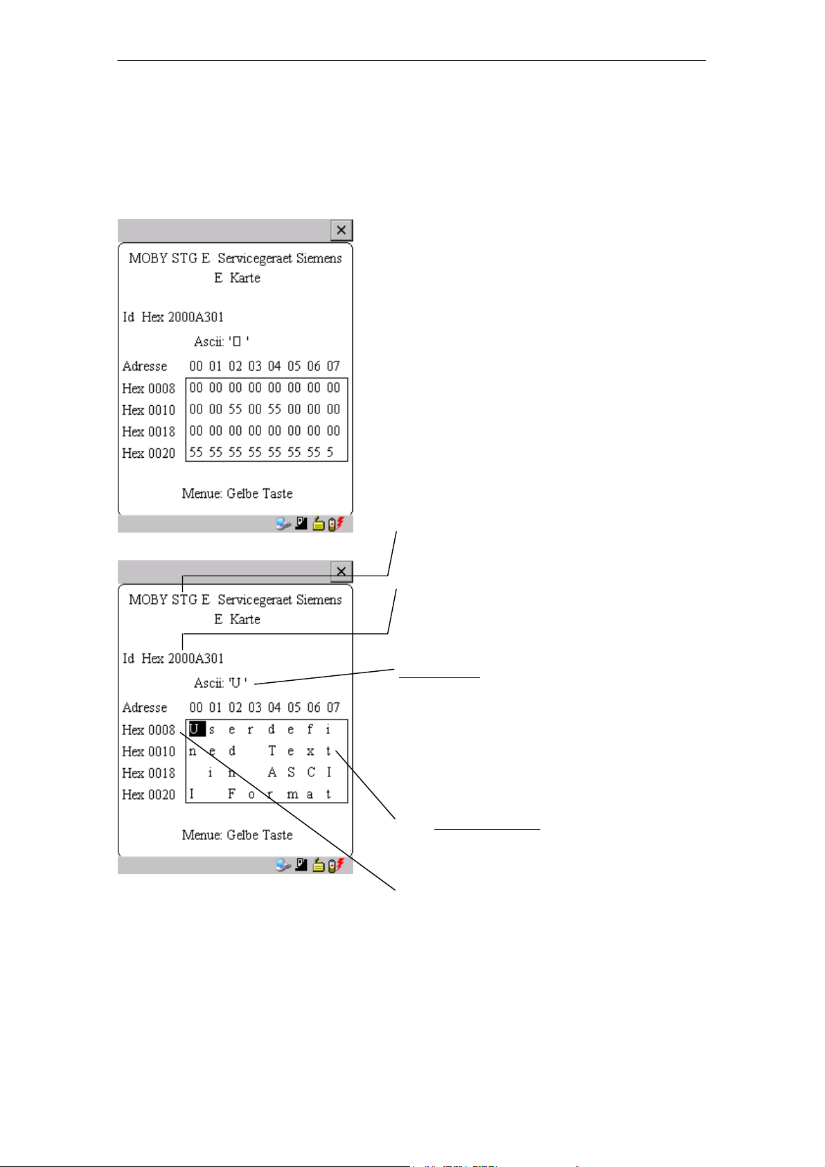
Die Programme “MOBY D/E/I”
A 05/07
4.1 Der Dateneditor
Das Editieren der MDS-Daten kann im Editorfenster in Hexadezimal oder in
ASCII erfolgen. Die Umschaltung erfolgt im Menü EDITOR/ANZEIGE.
Im Editor ist immer die gesamte Größe
eines MDS-Speichers abgebildet. Sie
können mit den Cursorfunktionen zu den
einzelnen Adressen gelangen. Ein
Sprung zu einer beliebigen Adresse
kann mit der “Tab”-Taste durchgeführt
werden (siehe Kap. 4.4.1)
Anzeige des aktuell eingestellten Lesekopfes (vgl. Kap. 4.5.1)
Die TagId des MDS wird nur bei
MOBY D/E angezeigt. Sie ist gültig
nach dem Ausführen der Funktion
“MDS/Lesen-Schreiben-LeseTagId”
Datumfeld:
Das Datum, an dem sich der Cursor befindet, wird alternativ in den Formaten
Hex, Dec, ASCII oder Bin dargestellt.
Mit der Funktion “Editor/Datum editieren”
kann der Wert im Datumfeld verändert
werden.
Das Editor-Fenster beinhaltet die MDSDaten. Standardmäßig werden 32 Byte
dargestellt.
MDS-Adressen werden hexadezimal
oder dezimal dargestellt.
D-14
STG Hand-Held Terminal PRO
(5)J31069-D0126-U001-A6-7418
 Loading...