How it Works
Log In / Sign Up
Buy Points
How it Works
FAQ
Contact Us
Questions and Suggestions
Users
Siemens
Loading...
M
MKB-4
MKB-5
MKB-5C
MKK18RNFF0
MLC
MM110
MM12
MM150
MM220
MM25
MM300
MM37
MM4
MM400
MM440
2
MM55
MM550
MM75
MM750
MM8000
3
MMB-3
MMB3-ALD-UK
MMI
2
MOBIC T8 for Windows CE 3.0
Mobile
Mobile 750
Mobile CF62T
mobile phone
Mobile Phones DK-9490 Pandrup
Mobilett
2
Mobilett Plus
MOBILETT XP
2
MOBILETT XP ECO
MOBILETT XP Hybrid
MOBILITY TOOLKIT FOR JAVA DEVELOPMENT 1.1
MOBY D
MOBYD SLGD10
MOBYD SLGD11
MOBYD SLGD12
MOBYDSTG
MOBY E
MOBYE SLA71
MOBYE-SLG75
2
MOBYESTG
MOBYE XXX70A0
MOBYE XXX70A1
MOBYE XXX72
MOBY F
MOBYF-XXX80
3
MOBY I
MOBY I ASM 421
MOBYI SLG40
MOBYI-SLG40N
3
MOBYI SLG40S
MOBYI-SLG40SN
3
MOBYI SLG41
MOBYI SLG41CN
MOBYI SLG41N
MOBYI SLG42
MOBYI-SLG42N
2
MOBYI SLG43
MOBY series
MOBY U
MOBYU-MDSU313
4
MOBYU-MDSU315
2
MOBYU-MDSU524
4
MOBYU-MDSU525
2
MOBYU-MDSU589
4
MOBYU-SLGU92-0
4
MOBYU-SLGU92-1
4
MOBYU STGU
MOD-16
Model 240
Modem Block
Modularis Litho Vario
Modularis Uro
Modularis Uro Plus
9
Modularis Vario
Modular Type Packages
MOJ6024DCL
Monitor 44
Monitor 44cm
3
MOTION
Motion 101 BTE
5
Motion 300
Motion 300 WL
Motion 301
3
Motion 301 BTE
4
Motion 301 WL
Motion 500
Motion 500 WL
MOTION 501
4
Motion 501 BTE
5
Motion 501 WL
Motion 700
Motion 700 WL
MOTION 701
4
Motion 701 BTE
5
Motion 701 WL
MOTION BTE
2
Loading...
Loading...
Nothing found
MOBYE-SLG75
Users Manual
1 pgs
11.37 Kb
0
Users Manual
13 pgs
256.95 Kb
0
Table of contents
Loading...
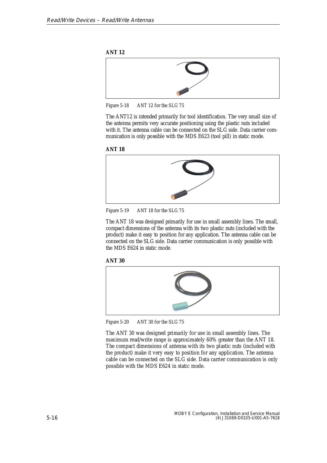
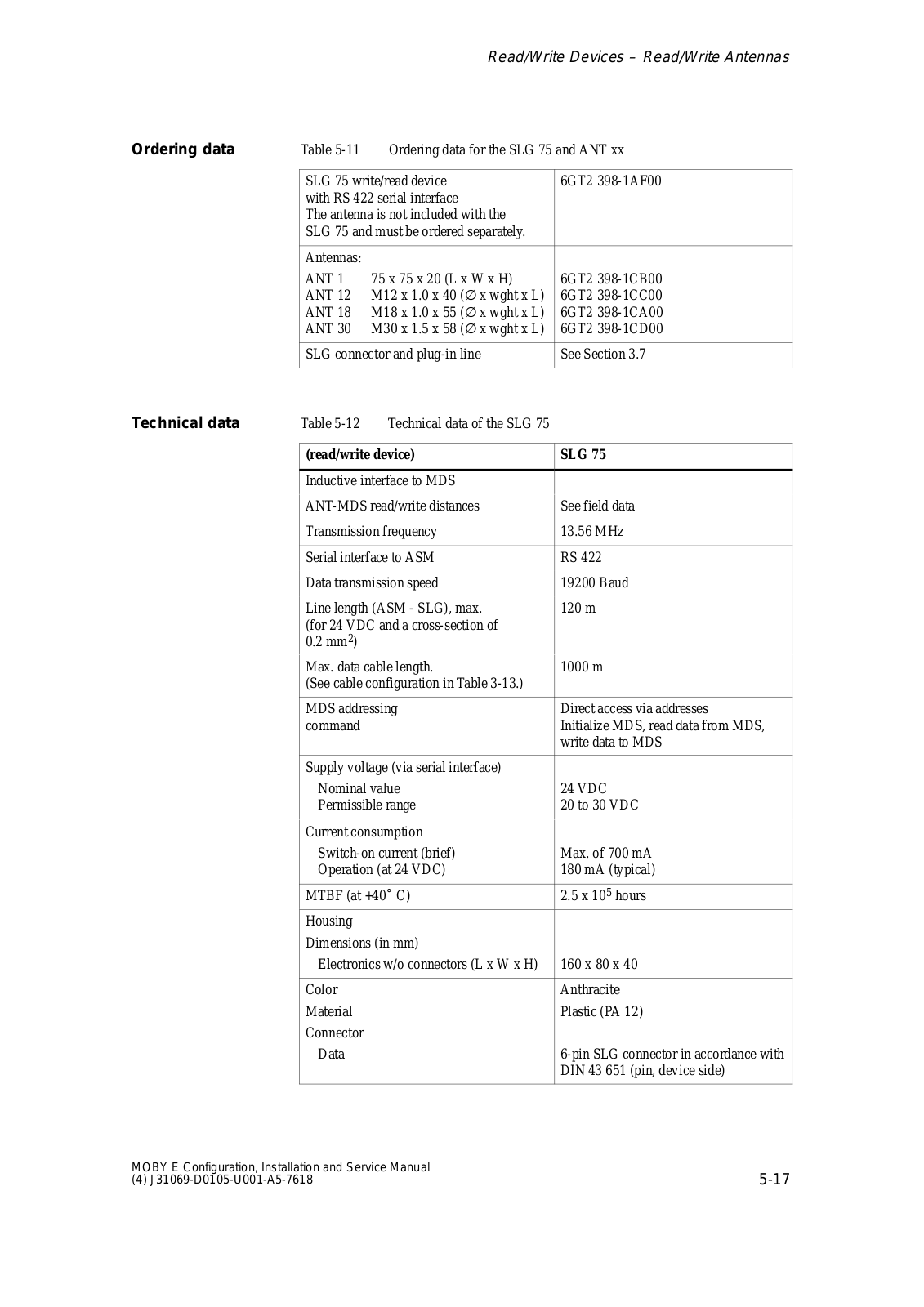
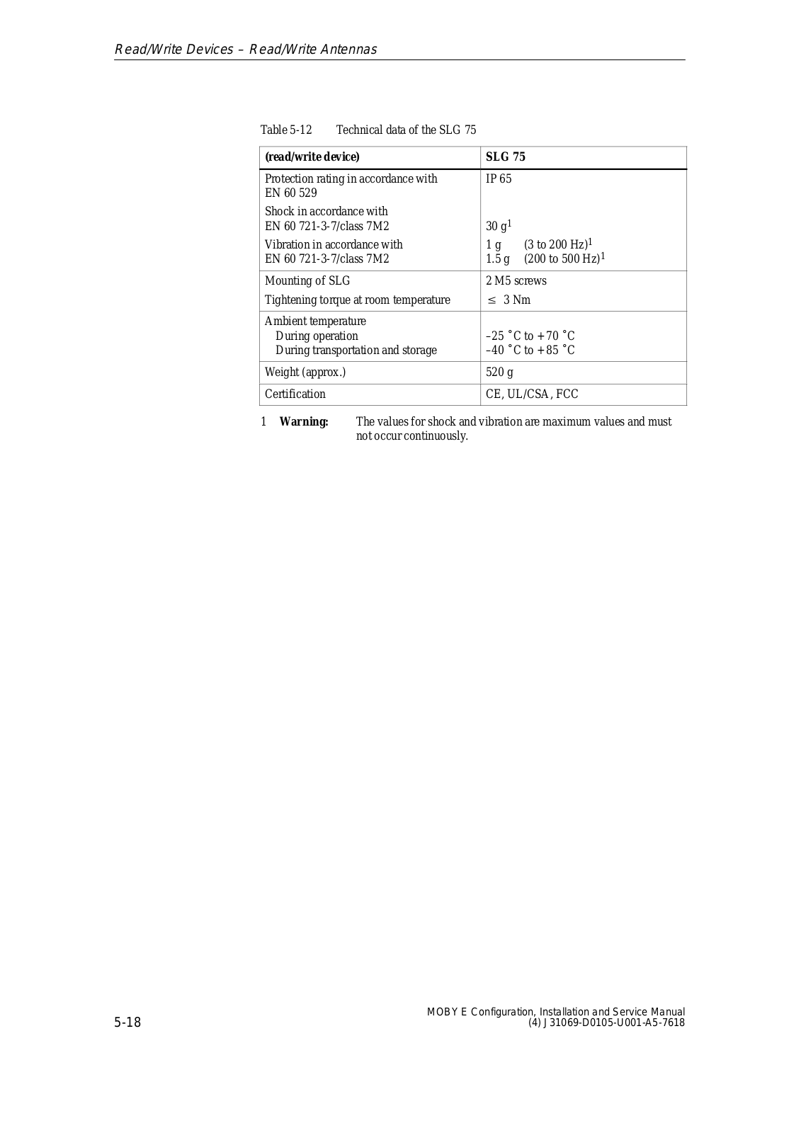
Siemens MOBYE-SLG75 Users Manual
...
Siemens Users Manual
Download
Specifications and Main Features
Frequently Asked Questions
User Manual
Download
Page 1
Page 2
Page 3
Page 4
Page 5
Page 6
Page 7
Page 8
Page 9
Page 10
Page 11
Page 12
Page 13
Loading...
+
hidden pages
Unhide
You need points to download manuals.
1 point = 1 manual.
You can buy points or you can get point for every manual you upload.
Buy points
Upload your manuals
 Loading...