

Siemens IL440 Datasheet
IL440
TRIAC PREDRIVER
NON-ZERO CROSSING
OPTOCOUPLER
FEATURES
• 600 V Blocking V oltage
• 7 mA Maximum Trigger Current
• Isolation Voltage, 3750 VAC, t=1 sec.
• Isolation Materials per UL94
APPLICATIONS
• High Current Triac Driver
• Solid State Relays
• Switch Small AC Loads
DESCRIPTION
The IL440 consists of a GaAs infrared emitter optically
coupled to a silicon planar triac chip with a non-zero
crossing network. The two semiconductors are
assembled in a 6 pin dual-in-line plastic package. The
output detector is capable of blocking up to 600 volts
which permits control of off-line voltages up to 240
VAC. The IL440 can handle currents up to 100
mA
.
RMS
Maximum Ratings
Emitter
Reverse Voltage ..................................................... 5 V
Forward Current ................................................60 mA
Surge Current (P.W.<10 µ
s).....................................3 A
Power Dissipation............................................100 mW
Junction Temperature........................................ 100 °
Detector
Peak Off-state Voltage.........................................600 V
On-state RMS Current......................................100 mA
Peak Surge Current (t
≤
10 ms)............................1.2 A
p
Peak On-state Current.............................................2 A
Power Dissipation............................................300 mW
Junction Temperature........................................ 125 °
Package
Isolation Voltage, 1 sec................................ 3750 VAC
per Standard Climate 23 °
C/50% RH,
DIN 50014
Creepage.......................................................... ≥
Clearance.......................................................... ≥
Isolation Resistance
V
=500 V, T
IO
V
=500 V, T
IO
Total Power Dissipation, T
=25 ° C ..................................... ≥ 10
A
=100 ° C ................................... ≥ 10
A
=25 ° C...................330 mW
A
Storage Temperature Range.............–55 °
Operating Temperature Range..........–40 °
7 mm
7 mm
12
11
C to +125 ° C
C to +100 ° C
Junction Temperature......................................... 100 °
Lead Soldering Temperature
(2 mm from case, t<10 s.)..............................260 °
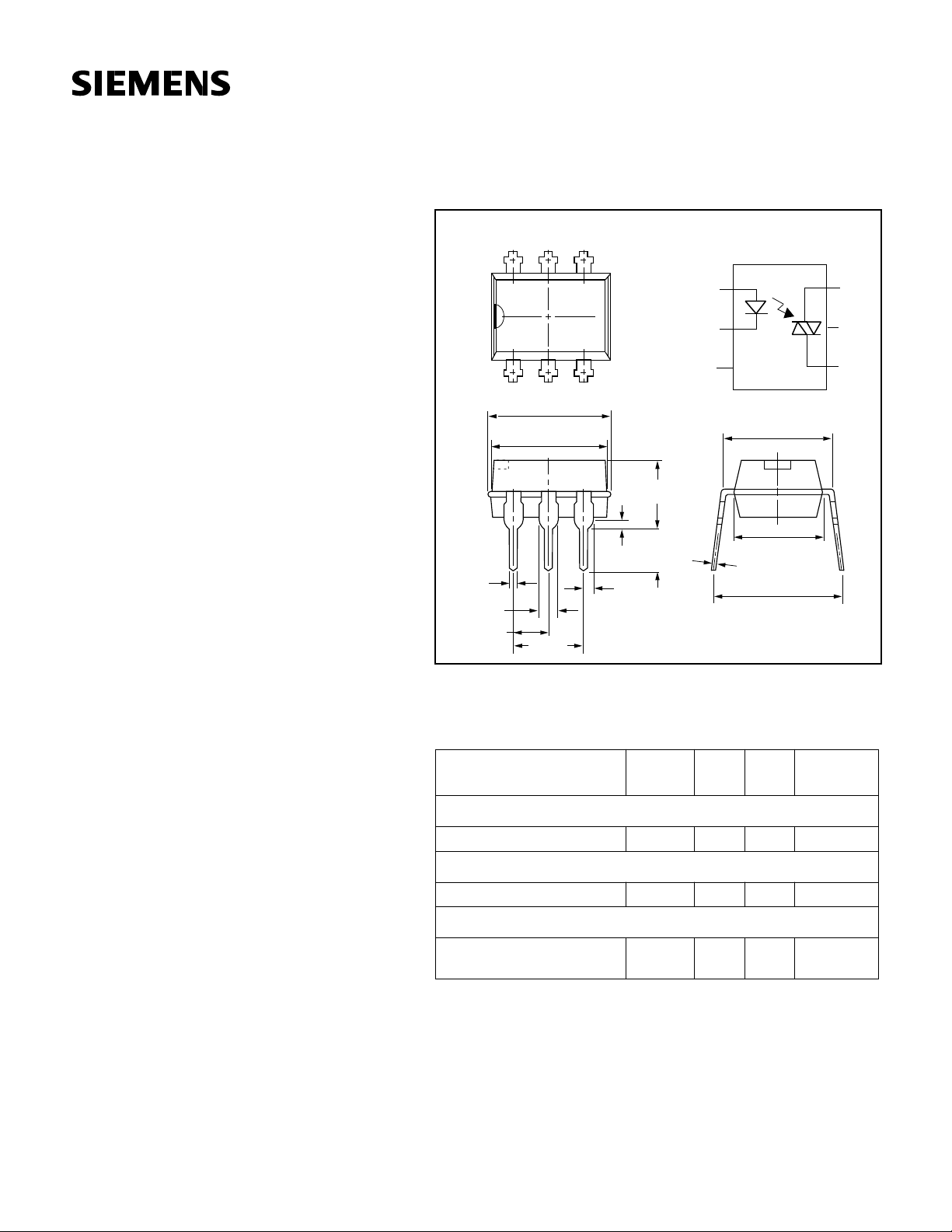
Package Dimensions in inches (mm)
.023 (.58)
.019 (.48)
.061 (1.54)
.057 (1.44)
.100 (2.54)
Maximum Safety Ratings
C
65
1
.346 (8.8)
.339 (8.6)
.2 (5.08)
2
Max.
Max.
4
1
A
2
K
3
NC
3
.308 (7.82)
.292 (7.42)
.193 (4.9)
Max.
.025
.04
(.5)
.026
(.65)
.130
(3.3)
(6.4)
.014 (.35)
Max.
.382 (9.7)
.327 (8.3)
This device is used for protective separation against electrical shock
within the maximum safety ratings. This must be ensured by protective
circuits in the applications.
Parameter Symbol Max. Unit
C
Emitter
Forward Current I
F
130 mA
Detector
Power Dissipation P
D
300 mW T
Coupled Device
Ω
Ω
Rated Impulse Voltage
Sample Test
V
IOTM
6kVt
C
C
6
MT1
5
NC
4
MT2
Test
Condition
≤ 25 ° C
A
= 10 s,
T1
=60 s
t
test
5–127

Electrical Characteristics, T
=25 ° C
A
Parameter Symbol Min. Typ. Max. Unit Test Condition
Emitter
Forward Voltage V
Breakdown Voltage V
Junction Capacitance C
F
BR
J
5VI
1.25 1.6 V I
50 pF V
=50 mA
F
=10 µ A
R
=0 V, f=1 MHz
R
Detector
Off-state Output Terminal Voltage V
Peak On-state Voltage V
DRM
TM
Critical Rate of Rise of Off-state Voltage (dv/dt)
(dv/dt)
600 V I
1.5 3 V I
cr
0.13 0.25 V/ µ sI
crq
50 V/ µ sI
=500 nA
DRM
=100 mA, I
TM
=0, V
F
S
=30 mA, V
F
=240 V
Coupled Device
Input Trigger Current I
Holding Current I
FT
H
5 7 mA V
1mAI
=6 V, R
T
≥
10 mA, V
F
=150
L
FT
=60 V
S
≥ 3 V
S
=30 mA
RMS
RMS
Ω
5–128
IL440
 Loading...