

)
)
.
.
e
IL420
600 V TRIAC DRIVER OPTOCOUPLER
FEATURES
• High Input Sensitivity I
=2 mA
FT
• Blocking V oltage, 600 V
• 300 mA On-State Current
• High Static dv/dt 10,000 V/ µ s
• Inverse Parallel SCRs Provide Commutating
dv/dt >2K V/ µ s
• Very Low Leakage <10 µ A
• Isolation Test Voltage from Double Molded
Package 5300 VAC
RMS
• Small 6-Pin DIP Package
• Underwriters Lab File #E52744
• VDE 0884 Available with Option 1
Maximum Ratings
Emitter
Reverse Voltage................................................ 6 V
Forward Current........................................... 60 mA
Surge Current..................................................2.5 A
Power Dissipation.......................................100 mW
Derate from 25 °
Thermal Resistance..................................750 °
C ................................1.33 mW/ ° C
C/W
Detector
Peak Off-State V oltage...................................600 V
Peak Reverse Voltage....................................600 V
RMS On-State Current.................................300 mA
Single Cycle Surge............................................ 3 A
Total Power Dissipation..............................500 mW
Derate from 25 °
Thermal Resistance...................................150 °
C ..................................6.6 mW/ ° C
C/W
Package
Storage Temperature................... –55 ° C to +150 ° C
Operating Temperature............... –55 °
Lead Soldering Temperature..............260 °
Isolation Test V oltage.........................5300 VAC
C to +100 ° C
C/5 sec.
RMS
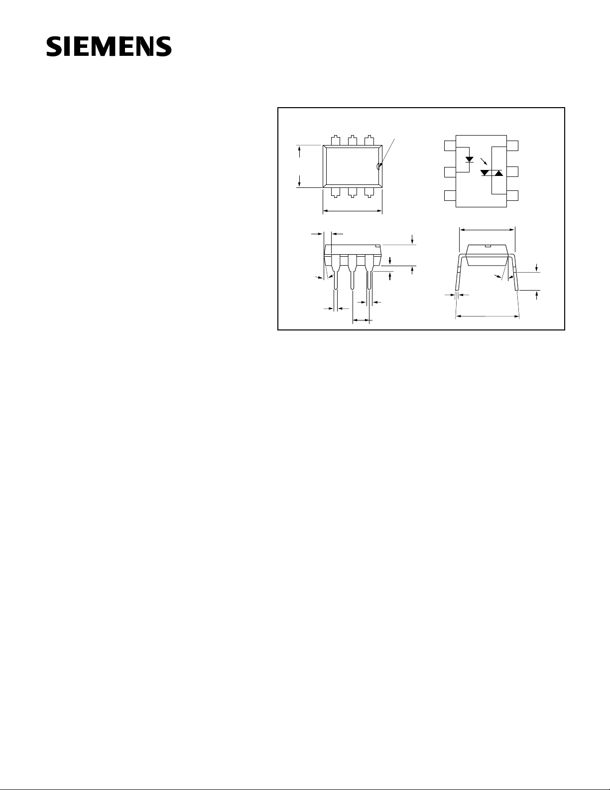
Dimensions in inches (mm)
Pin One ID
12
5
6
Anode
Cathode
.130 (3.30)
.150 (3.81)
.020 (.051) min.
.031 (0.80)
.035 (0.90)
.100 (2.54) typ.
LED
1
LED
2
NC
3
*Zero Crossing Circuit
.300 (7.62)
18° typ.
.010 (.25)
.014 (.35)
.300 (7.62)
.347 (8.82)
typ.
Triac
6
MT2
Substrat
5
do not
connect
Triac
4
MT1
.110 (2.79
.150 (3.81
248 (6.30)
256 (6.50)
.039
(1.00)
Min.
4°
typ.
.018 (0.45)
.022 (0.55)
3
4
.335 (8.50)
.343 (8.70)
DESCRIPTION
The IL420 consists of a GaAs IRLED optically coupled to a photosensitive non-zero crossing TRIAC network. The TRIAC consists of two
inverse parallel connected monolithic SCRs. These three semiconductors are assembled in a six pin 0.3 inch dual in-line package, using high
insulation double molded, over/under leadframe construction.
High input sensitivity is achieved by using an emitter follower phototransistor and a cascaded SCR predriver resulting in an LED trigger
current of less than 2 mA (DC).
The IL420 uses two discrete SCRs resulting in a commutating dV/dt of
greater than 10KV/ms. The use of a proprietary
dv/dt clamp
results in a
static dV/dt of greater than 10KV/ms. This clamp circuit has a MOSFET
that is enhanced when high dV/dt spikes occur between MT1 and MT2
of the TRIAC. When conducting, the FET clamps the base of the phototransistor, disabling the first stage SCR predriver.
The 600 V blocking voltage permits control of off-line voltages up to 240
V AC, with a safety factor of more than two, and is sufficient for as much
as 380 VAC.
The IL420 isolates low-voltage logic from 120, 240, and 380 V AC lines to
control resistive, inductive, or capacitive loads including motors, solenoids, high current thyristors or TRIAC and relays.
Applications include solid-state relays, industrial controls, office equipment, and consumer appliances.
5–1
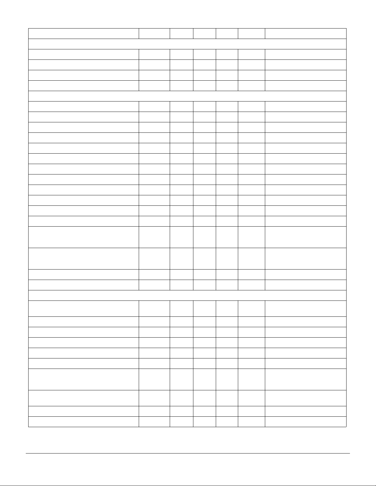
Characteristics
Emitter
Forward Voltage V
Reverse Current I
Capacitance C
Thermal Resistance, Junction to Lead R
Output Detector
Off-State Voltage V
Reverse Voltage V
Off-State Current I
Reverse Current I
On-State Voltage V
On-State Current I
Surge (Non-Repititive) On-State Current I
Holding Current I
Latching Current I
LED Trigger Current I
Turn-On Time t
Turn-Off Time t
Critical State of Rise of Off-State Voltage
Critical Rate of Rise of Voltage at Current
Commutation dv/dt
Critical State of Rise of On-State Current di/dt
Thermal Resistance, Junction to Lead R
Insulation and Isolation
Critical Rate of Rise of Coupled Input/Output
Voltage dv
Common Mode Coupling Capacitor C
Package Capacitance C
Isolation Test Voltage, Input-Output V
Creepage
Clearance
Creepage Tracking Resistance per DIN IEC
112/VDE 0303, Part 1 group IIIa per DIN VDE
0110
Isolation Resistance R
Trigger Current Temperature Gradient
Capacitance Between Input and Output Circuit C
Symbol Min Typ Max Unit Condition
F
R
O
THJL
D (RMS)
R
D (RMS)
R (RMS)
TM
TM
TSM
H
L
FT
ON
OFF
dv/dt
cr
dv/dt
cr
crq
dv/dt
crq
cr
THJL
/dt 5000 V /µ sI
(IO)
CM
IO
ISO
424 460 V I
424 460 V I
10000
5000
10000
5000
5300 VAC
1.16 1.35 V I
0.1 10
µ AV
40 pF V
750
10 100
10 100
C/W
°
µ AV
µ AV
1.7 3 V I
300 mA PF=1.0, V
3 A f=50 Hz
65 500
µ A
5mAV
1 2 mA V
35
50
µ sV
µ s PF=1.0, I
V/ µ s
V/ µ s
V/ µ s
V/ µ s
8A/
150
µ
s
C/W
°
0.01 pF
0.8 pF f=1 MHz, V
RMS
=10 mA
F
=6 V
R
=0 V, f=1 MHz
F
=70 µ A
D(RMS)
=70 µ A
R(RMS)
=600 V, T
D
=600 V, T
R
=300 mA
T
=2.2 V
T
=5 V
AK
=V
RM
DM
V
=0.67 V
D
T
=25
°
C
j
Tj=80
°
C
V
=0.67 V
D
Tj=25
C
°
T
=80
C
°
j
=0 A, V
T
Relative Humidity ≤ 50%
≥ 7mm
≥ 7mm
CTI 175
12
≥
is
R
is
∆ I
/ ∆ T
FT
j
IO
10
11
≥
10
714
2pF V
Ω
Ω
µ
A/K
V
=500, T
IO
V
=500, T
IO
=0, f=1 kHz
R
=100
A
=100
A
=1.7 V
T(RMS)
=424 VAC
=300 mA
T
DRM
, di/dt
DRM
=V
RM
DM
=0 V
IO
=25
°
A
=100
A
°
C
°
C
15 A/ms
≤
crq
=424 VAC
C
C
°
5–2
IL420
 Loading...