

Siemens IL400 Datasheet
IL400
PHOTO SCR OPTOCOUPLER
FEATURES
• Turn On Current (IFT), 5.0 mA Typical
• Gate Trigger Current (IGT), 20 µ A
• Surge Anode Current, 1.0 Amp
• Blocking V oltage, 400 V
• Gate Trigger Voltage (VGT), 0.6 Volt
• Isolation V oltage, 5300 VA C
RMS
• Solid State Reliability
• Standard DIP Package
• Underwriters Lab File #E52744
DESCRIPTION
The IL400 is an optically coupled SCR with a Gallium
Arsenide infrared emitter and a silicon photo SCR
sensor. Switching can be achieved while maintaining
a high degree of isolation between triggering and load
circuits. The IL400 can be used in SCR triac and solid
state relay applications where high blocking voltages
and low input current sensitivity are required.
Maximum Ratings
Emitter
Peak Reverse Voltage........................................ 6.0 V
Peak Forward Current
(100 µ
s, 1% Duty Cycle)..................................1.0 A
Continuous Forward Current.............................60 mA
Power Dissipation at 25 °
Derate Linearly from 25 °
C .............................100 mW
C..........................1.3 mW/ ° C
Detector
Reverse Gate Voltage.........................................6.0 V
Anode Voltage (DC or AC Peak)........................400 V
Anode Current.................................................100 mA
Surge Anode Current (10 ms duration)...............1.0 A
Surge Gate Current (5 ms duration)................200 mA
Power Dissipation, 25 °
Derate Linearly from 25 °
C ambient .................200 mW
C........................2.11 mW/ ° C
Package
Isolation Voltage....................................5300 VAC
Isolation Resistance
V
=500 V, T
IO
V
=500 V, T
IO
=25 ° C ............................. min. 10
A
=100 ° C ........................... min. 10
A
RMS
12
11
Ω
Ω
Total Package Dissipation..............................250 mW
Derate Linearly from 25 °
Operating Temperature....................–55 °
Storage Temperature........................–55 °
C........................2.63 mW/ ° C
C to +100 ° C
C to +150 ° C
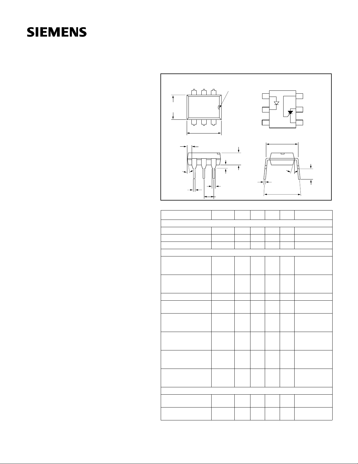
Package Dimensions in Inches (mm)
Pin One ID.
5
=25 ° C)
A
12
6
Symbol
.130 (3.30)
.150 (3.81)
.020 (.051) min.
.031 (0.80)
.035 (0.90)
.100 (2.54) typ.
Min. Typ. Max. Unit Condition
3
.248 (6.30)
.256 (6.50)
4
.335 (8.50)
.343 (8.70)
.039
(1.00)
min.
4°
typ.
.018 (0.45)
.022 (0.55)
Characteristics (T
Emitter
Forward Voltage V
Reverse Voltage V
Reverse Current I
F
R
R
5.0 V I
Detector
Forward Blocking
Voltage
Reverse Blocking
Voltage
On-state Voltage
Holding Current I
Gate Trigger
Voltage
Forward Leakage
Current
Reverse Leakage
Current
Gate Trigger Current I
V
DRM
V
DRRM
V
t
H
V
GT
I
D
I
R
GT
400 V
400 V
Package
Turn-0n Current I
FT
0.5 5.0 10.0 mA V
Isolation
Capacitance
1
Anode
NC
2
3
.300 (7.62)
typ.
18° typ.
.010 (.25)
.014 (.35)
.300 (7.62)
.347 (8.82)
Cathode
1.2 1.5 V I
10 µ AV
1.2 V I
500 µ AR
0.6 1.0 V V
0.2 2.0 µ AR
0.2 2.0 µ AR
20 50 µ AV
2 pF f=1 MHz
6
Gate
5
Anode
4
Cathode
.110 (2.79)
.150 (3.81)
=20 mA
F
=10 µ A
R
=5 V
R
R
=10 K
GK
T
=100 ° C
A
Id=150 µ A
R
=10 K
GK
T
=100 ° C
A
Id=150 µ A
=100 mA
T
=27 K
GK
V
=50 V
FX
=100 V
FX
R
=27 K
GK
R
=10 K
L
=27 K
GK
V
=400 V
RX
I
=0, T
F
A
=27 K
GK
V
=400 V
RX
I
=0, T
F
A
=100 V
FX
R
=27 K
GK
R
=10 K
L
=100 V
FX
R
=27 K
GK
Ω
Ω
Ω
Ω
Ω
Ω
=25 ° C
Ω
=25 ° C
,
Ω
Ω
Ω
5–116
 Loading...