

Siemens IL256A Datasheet
W
(
IL256A
AC INPUT PHOTOTRANSISTOR
SMALL OUTLINE
SURFACE MOUNT OPTOCOUPLER
NE
FEATURES
• Guranteed CTR Symmetry, 2:1 Maximum
• Bidirectional AC Input
Industry Standard SOIC-8 Surface
• Mountable Package
• Standard Lead Spacing, .05"
• Available in Tape and Reel Option
(Conforms to EIA Standard RS481A)
DESCRIPTION
The IL256A is an AC input phototransistor optocoupler. The device consists of two infrared emitters
connected in anti-parallel and coupled to a silicon
NPN phototransistor detector.
These circuit elements are constructed with a standard SOIC-8 foot print.
The product is well suited for telecom applications
such as ring detection or off/on hook status, given
its bidirectional LED input and guaranteed current
transfer ratio (CTR) minimum of 20% at I
= 10 mA.
F
Maximum Ratings
Emitter
Continuous Forward Current.........................60 mA
Power Dissipation at 25 °
Derate Linearly from 25 °
C...........................90 mW
C..................... 0.8 mW/ ° C
Detector
Collector-Emitter Breakdown Voltage.............. 30 V
Emitter-Collector Breakdown Voltage................ 5 V
Collector-Base Breakdown Voltage................. 70 V
Power Dissipation ..................................... 150 mW
Derate Linearly from 25 °
C..................... 2.0 mW/ ° C
Package
Total Package Dissipation at 25 ° C Ambient
(LED + Detector)....................................240 mW
Derate Linearly from 25 °
Storage Temperature .................. –55 °
Operating Temperature ............... –55 °
Soldering Time at 260 °
C..................... 3.1 mW/ ° C
C to +150 ° C
C to +100 ° C
C..............................10 sec.
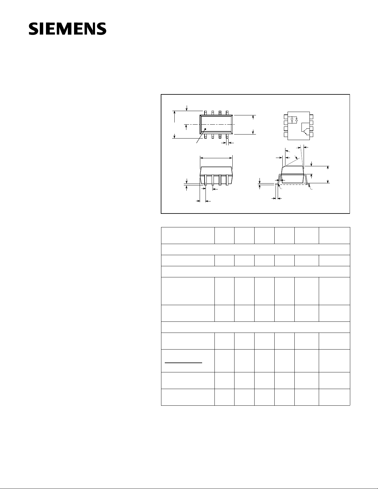
Dimensions in inches (mm)
.120±.005
(3.05±.13)
.240
6.10)
Pin One ID
.192±.005
(4.88±.13)
.004 (.10)
.008 (.20)
.021 (.53)
Characteristics (T
Emitter
Forward Voltage V
Detector
Breakdown Voltage
Collector-Emitter
Emitter-Collector
Collector Base
Leakage Current,
Collector-Emitter
Package
DC Current Transfer
Ratio
Symmetry
CTR at +10mA
=25 ° C)
A
CTR at –10 mA
Anode/
Anode
NC
NC
1
2
3
4
40°
5° max.
R.010
(.25) max.
Cathode
.154±.005
C
L
(3.91±.13)
.016 (.41)
.050 (1.27)
typ.
Symbol
BV
BV
BV
I
CTR 20 % I
Min. Typ. Max. Unit Condition
F
30
CEO
5
ECO
70
CBO
CEO
0.5 1.0 2.0
Cathode/
.015±.002
(.38±.05)
.008 (.20)
.020±.004
(.15±.10)
2 plcs.
1.2 1.5 V I
50
10
90
550nA V
7°
.058±.005
(1.49±.13)
V
V
V
8
NC
7
Base
6
Collector
5
Emitter
.125±.005
(3.18±.13)
Lead
Coplanarity
±.0015 (.04)
max.
= ± 10 mA
F
I
=1 mA
C
I
=100 µ A
E
I
=100 µ A
C
=10 V
CE
= ± 10 mA,
F
V
=5 V
CE
Saturation Voltage,
Collector-Emitter
Isolation Voltage,
Input to Output
5–1
V
V
CEsat
2500 VAC
IO
0.4 I
RMS
= ± 16 mA,
F
I
=2 mA
C
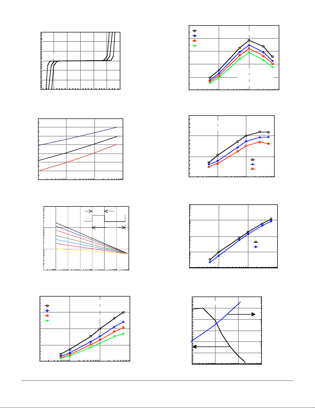
Figure 1. LED forward current versus forward voltage
60
40
85°C
20
25°C
0
-55°C
-20
-40
-60
-1.5 -1.0 -0.5 0.0 0.5 1.0 1.5
IF - LED Forward Current - mA
VF - LED Forward Voltage - V
Figure 2. Forward voltage versus forward current
1.4
1.3
1.2
1.1
1.0
0.9
Vf-Forward Voltage - V
0.8
0.7
.1 1 10 100
Ta = -55°C
Ta = 25°C
Ta = 100°C
If - Forward Current - mA
Figure 5. Normalized saturated CTR
1.0
0.8
Ta = 25°C
Ta = 50°C
Ta = 70°C
Vce(sat) = 0.4V
Ta = 100°C
0.6
0.4
Normalized CTR
0.2
Normalized to:
If = 10 mA. Vce =10V
Ta = 25°C
0.0
.1 1 10 100
If - LED Current - mA
Figure 6. Normalized CTRcb
1.5
Normalized to:
If=10mA, Ta=25°C
1.0
0.5
Normalized CTRcb
0.0
.1 1 10 100
If - LED Current -mA
25°C
50°C
70°C
Figure 3. Peak LED current versus duty factor, Tau
10000
Duty Factor
.005
1000
If(pk) - Peak LED Current - mA
.01
.02
.05
.1
.2
.5
100
10
10-610-510-410-310-210-110010
t - LED Pulse Duration - s
τ
t
τ
DF = /t
1
Figure 4. Normalized CTR versus If and Ta
2.0
Ta = 25°C
1.5
Ta = 50°C
Ta = 70°C
Ta = 100°C
1.0
Normalized CTR
0.5
0.0
.1 1 10 100
If - LED Current - mA
Normalized to :
If = 10 mA, Vce =10V
Ta = 25°C
Figure 7. Photocurrent versus LED current
1000
100
10
25°C
70°C
1
Icb - Photocurrent - µA
.1
.1 1 10 100
If - LED Current - mA
Figure 8. Base current versus If and HFE
700
Vce=0.4V, Ta=25°C
600
500
400
300
HFE - Transistor Gain
200
100
1 10 100 1000
Ib - Base Current - µA
100
10
1
If- LED Current-mA
.1
5–2
IL256A
 Loading...