

Siemens A80407-01, GCP 4000 Quick Reference Manual

QUICK REFERENCE GUIDE
DT INSTALLATION PROCEDURE A FOR
GCP 4000 DISPLAY MODULE A80407-01
(AND EARLY -03) USING A COMPACT
FLASH DEVICE
Document Number SIG-QG-09-02
Version B.1
The following procedure should be used when upgrading
the Diagnostic Utility (DT) in a GCP 4000 Display Module,
P/N 8000-80407-0001 and early versions of P/N 800080407-0003 (see note below).
NOTE
If the A80407-03 Display Module is labeled DISPLAY
II, you must use DT Installation Procedure B
(document No. SIG-QG-09-03) to install the DT
software.
INSTALLING THE DT IN GCP 4000 DISPLAY MODULE
A80407-01 OR EARLY A80407-03
To perform this procedure you will need a preloaded Compact Flash device, Siemens part number
Z224-9V244-A010, containing the latest DT software
version that is compatible with the curren tly
installed MCF. In addition to the preloaded Compact
Flash device you will need a PCMCIA adapter
module to install the Compact Flash device in the
Display Module. This adapter module can be
purchased from Siemens by ordering P/N Z714 02115-0000.
NOTE
Upgrading the DT Utility in the Display Module will
NOT interfere with the safe operation of the
highway crossing warning system.
1. Locate and remove the A80407 display mod ule from
the GCP 4000 chassis.
2. Locate the boot DIP switches on the top edge of the
Display Module (accessible through the slot in the top
of the Display Module case, figure #1). The Display
Module boot DIP-switch normal positions are: switch
1= OFF, switch 2 = ON. For Phase 1 stylus calibration,
position both switches to the OFF position (see figure
#2 below).
#1
#2
3. Insert the Siemens provided Compact Flash memory
device into the PC card adapter. Then install the
adapter in the A80407 Display Module through the
slot in the top of the Display Module case (figure #3).
Reinstall the Display Module in the GCP 4000 chassis
as shown in figure #4 below. Apply power to the GCP
4000 if not already powered up.
#3
#4
4. With the use of the stylus, calibrate the display by
tapping the + sign as it appears on the display (figure
#5). At the end of this calibration process a 30
second timer will run (figure #6). Tap the display one
more time before this timer expires to save the new
display module calibration settings.
#5
#6
5. The screen shown in figure #7 indicates the
completion of Phase 1 and provides additi onal
information in preparation for Phase 2. Remove the
A80407 Display Module from the 4000 chassis and
then remove the PC card adapter and Compact Flash.
Set both Display Module DIP switches back to the
normal position: switch 1 = OFF and switch 2 = ON.
Reinstall the PC card adapter and Compact Flash in
the A80407 Display Module. Reinstall the Display
Module in the GCP 4000 chassis.
#7
#8
6. After reinstalling the A80407 module in the GCP 4000,
the display will execute its b oot cycle. After the
completion of the boot up process the display will
show a prompt asking if “you want to reformat the
FlashFX Disk?”. Select Yes (f igure #9). When the
WARNING appears select OK (figure #10).
#9
NOTE
In the following figures the DT version number
at the top of the screen and the OS Build
number at the bottom will vary depending on
the DT and OS software versions installed.
Normal position
ON
OFF
1
2
calibration position
ON
OFF
1
2
3
4
Copyright© 2008-2014 Siemens
All rights reserved
2
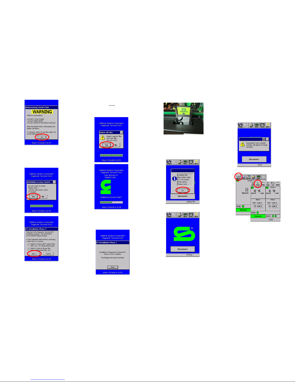
#10
7. After selecting OK the next screen (figure #11) will
prompt one more time to erase the FlashFX Disk.
Select Yes. At this point Phase 2 DT installation will
begin. Ensure that the two option boxes are checked
as shown in figure #12 below and then select Next >.
#11
#12
8. The following display will ask you if you want to
delete the support files, select Yes to start the
process.
NOTE
This upgrade may take up to 10 minutes to
complete. Do not disturb the system during this
process.
9. At the completion of this process, a screen message
will indicate that the installation has been completed
(see below). Remove the A80407 Displ ay Module
from the GCP chassis and then remove the PC card
adapter and Compact Flash.
10. Reinstall the A80 407 Display Module in the GCP 4000.
After completion of the boot process the following
message will appear: “Creating file description data.
DT will restart when done” (see figure #13). Select
OK to initiate the process.
#13
11. The process will be followed by the screen shown in
figure #14, and the display will again reboot. At the
conclusion of this boot cycle the display will resume
normal operation and will indicate the conditions of
the GCP 4000 and highway crossing warning system.
#14
12. This concludes the DT software installation and
upgrade. NO ADDITIONAL TESTING IS REQUIRE D.
For verification of the DT installation, select MORE
(MAIN in DT 5.0.7 and later) on the Track status
screen and then select HELP (ABOUT in DT 5.0.7 and
later) on the subsequent scr een to view the DT
version. Verify that the display indicates the proper
DT version (e.g., 5.0.7).
*Refer to GCP 4000 Crossing System Maint ainer’s Handbook,
Document Number: SIG-00-04-02 Version B, dated March
2007 or to 4000 GCP Crossing System Field M anual, Document
Number SIG-00-08-10 Version B or later, for additional
information regarding installation of DT software in a GCP
4000 Display Module
5 6 8
7
PRINTED IN USA
 Loading...