

Siemens GAMMA instabus 5WG1 220-2AB21, GAMMA instabus 5WG1 220-2AB31 Operating And Mounting Instructions Manual
GAMMA instabus
Taster-Schnittstelle UP 220/21 UP 220 /31
Push Button Interface UP 220/21 UP 220/31
5WG1 220-2AB21
5WG1 220-2AB31
Bedien- und Montageanleitung
Operating and Mounting Instructions
Stand: August 2009
Issued: August 2009
Bild / Figure 1a
Bild / Figure 1b
D
Produkt- und Funktionsbeschreibung
Die Taster-Schnittstellen UP 220/21 und UP 220/31 sind Binärein- und ausgabegeräte zum Einlegen in Geräteverbindungsdosen (∅ 60 mm, 40 mm tief).
Jeder der zwei (UP 220/21) bzw. vier (UP 220/31) Kanäle kann
wahlweise als Eingang für potentialfreie Schalter-/ Tasterkontakte oder als Ausgang zur Ansteuerung einer Leuchtdiode
(LED) genutzt werden. Die erforderliche Spannung wird von der
Taster-Schnittstelle geliefert (keine zusätzliche Spannungsquelle
erforderlich).
An eine Taster-Schnittstelle UP 220/21 können z.B. bis zu zwei
Schalter / Taster mit je einem potentialfreien Kontakt oder z.B.
ein Doppeltaster mit zwei potentialfreien Kontakten angeschlossen werden. An eine Taster-Schnittstelle UP 220/31 können z.B. bis zu vier Schalter / Taster mit je einem potentialfreien
Kontakt oder z.B. bis zu zwei Doppeltaster mit je zwei potentialfreien Kontakten angeschlossen werden.
Der Anschluss erfolgt über einen Leitungssatz, der fest an die
Taster-Schnittstelle angeschlossen ist. Die Verbindungsleitungen zwischen Schaltern / Tastern und der Taster-Schnittstelle
dürfen maximal bis auf 10 m verlängert werden. Dabei ist zu
beachten, dass die Leitungspaare verdrillt zu führen sind.
Über die angeschlossenen Schalter/ Taster können z.B. Befehle
an Aktoren zum definierten Ein-/Ausschalten oder zum Dimmen
von Leuchten, zum Auf-/Abfahren bzw. zum Lamellenverstellen
von Jalousien gegeben werden.
Für jeden Kanal, der als Ausgang parametriert ist, steht ein
Ausgangsstrom bis zu 2mA zur Ansteuerung einer Leuchtdiode
zur Verfügung.
Mit Hilfe der ETS können das Applikationsprogramm ausgewählt, die spezifischen Parameter und Adressen vergeben und
in die Taster-Schnittstelle UP 220/21 oder UP 220/31 übertragen werden.
Weitere Informationen
http://www.siemens.de/gamma
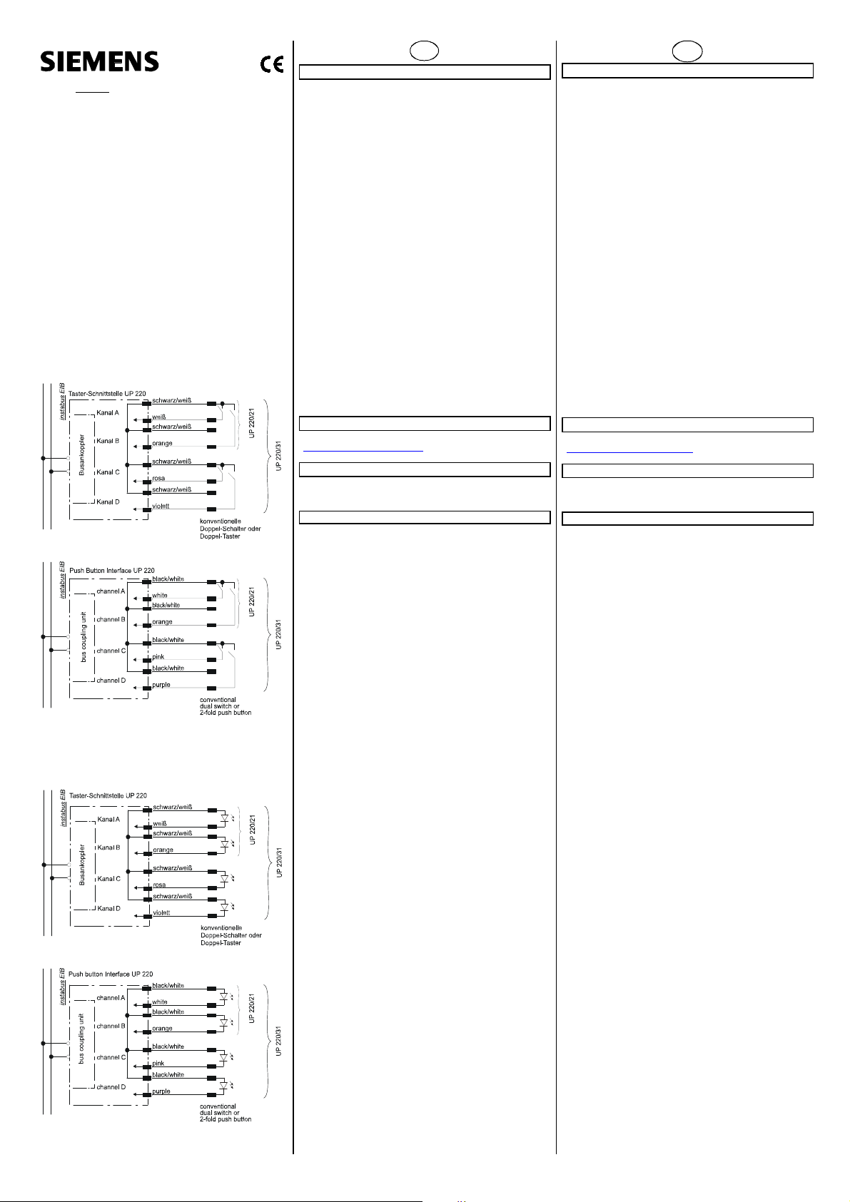
Anschlussbeispiel
mit Tastern: siehe Bild 1a
mit LEDs: siehe Bild 1b
Technische Daten
Spannungsversorgung
• Busspannung: erfolgt über die KNX/EIB Buslinie
Eingänge
• Eingangssignalspannung:
wird von der Tasterschnittstelle geliefert.
Bei geöffnetem Kontakt ca. 29V DC (Busspannung)
• Eingangssignalstrom:
bei geschlossenem Kontakt: pro Kanal 0,2mA DC.
im Moment des Schließens: Impuls 0,1A
• Eingangssignalverzögerung:
50ms inkl. Kontaktentprellung
• Eingangssignaldauer:
mindestens 50ms
• Eingangsverhalten:
parametrierbar
• Signalleitungssatz:
- Länge: 280mm ungeschirmt, verlängerbar bis auf
max. 10 m (pro Kanal) mit verdrillter, ungeschirmter Leitung
Freie Enden nicht benötigter Adern sind zu isolieren!
- Querschnitt: ca. 0,22mm² (0,56mm Ø)
Ausgänge
• Ausgangssignalspannung:
wird von der Tasterschnittstelle geliefert;
ca. DC 4,7V über 1,9kOhm Vorwiderstand (eingebaut);
Anode der LEDs an Anschluss 1 (schwarz/weiß) , Kathode an
Anschluss 2 (einfarbiger Leiter);
• Ausgangsstrom:
Wird der Ausgang kurzgeschlossen, so ergibt sich ein Strom
von ca. 2,5mA;
Die anzuschließenden LEDs müssen für eine Impulsbelastung von min. 100mA (tp 10μs) spezifiziert sein
Anschlüsse
• Signaleingänge / LED-Ausgänge: Leitungen
• Buslinie: Busklemme schraubenlos
0,6 ... 0,8mm Ø eindrähtig
Mechanische Daten
• Abmessungen (L x B x H): 42 mm x 42 mm x 8,5 mm
im Bereich der Busklemme ist die Höhe 11mm
• Gewicht: ca. 22g
Elektrische Sicherheit
• Schutzart (nach EN 60529): IP 20
Umweltbedingungen
• Umgebungstemperatur im Betrieb: - 5 ... + 45°C
• Lagertemperatur: - 25 ... + 70°C
• rel. Feuchte (nicht kondensierend): 5% bis 93%
Prüfzeichen
KNX/EIB
Product and Applications Description
The push button interfaces UP 220/21 and UP 220/31 are binary
input and output devices for installation in in-wall boxes
(∅ 60 mm, depth: 40 mm).
Each of the two (UP 220/21) resp. four (UP 220/31) channels
may be used either as an input for potential-free switch / push
button contacts or as an output for control of a light emitting diode (LED). The required scanning / control voltage is
provided by the push button interface (requires no additional
power supply).
For example, up to 2 switches/push buttons with one potentialfree contact each or one 2-fold push button with two potentialfree contacts may be connected to a push button interface UP
220/21. Up to 4 switches/push buttons with one potential-free
contact each or up to two 2-fold push buttons with two potential-free contacts each may be connected to a push button interface UP 220/31.
The connection is carried out via a cable set which is permanently connected to the push button interface. The connecting
cables between switches/push buttons and the push button interface may be extended up to 10 m. It must be ensured that
twisted cable pairs are used.
Commands can be given to actuators via the connected
switches/push buttons, e.g. for defined switching on/off, for
dimming fluorescent lamps or for raising/lowering venetian
blinds and adjusting the louvres.
Each channel, which is configured as an output, can drive an
output current of up to 2mA for controlling a light emitting diode
(LED).
With the ETS the application program is selected, its parameters and addresses are assigned appropriately, and downloaded
to the push button interface UP 220/21 or UP 220/31.
Additional Information
http://www.siemens.com/gamma
Example of Operation
with push buttons: see figure 1a
with LED’s: see figure 1b
Technical Specifications
Power supply
• Bus voltage: via KNX/EIB bus line
Inputs
• input signal voltage:
provided by the push button interface.
approx. 29 V DC (bus voltage) when the contact is opened
• input signal current:
when contact is closed: 0.2 mA DC per channel
at moment of closing: pulse 0.1 A
• input signal delay:
50 ms including contact debounce
• duration of input signal:
min. 50 ms
• input characteristic:
configurable
• signal cable set:
- length: 280 mm unshielded, may be extended up to
10 m (per channel) with twisted, unshielded cable
Unused free ends must be insulated!
- cross-section: approx. 0.22 mm² (0.56 mm Ø)
Outputs
• output signal voltage:
provided by the push button interface.
approx. DC 4.7V across 1.9kOhm resistor (built-in)
Connect anode of LED with terminal 1 (black/white), cathode
with terminal 2 (colored wire)
• output current:
When the output is short-circuited the output current is
approx.2.5mA;
The connected LED’s must be specified for an impulse load
of min. 100mA (tp 10μs)
Connections
• signal inputs / LED outputs: cables
• bus line: screwless bus terminal
Ø 0.6...0.8 mm single-core
Physical specifications
• dimensions (L x W x H): 42 mm x 42 mm x 8.5 mm
around the bus terminal the height is 11mm
• weight: approx. 22 g
Electrical safety
• protection (according to EN 60529): IP 20
Environmental specifications
• ambient operating temperature: - 5 ... + 45 °C
• storage temperature: - 25 ... + 70 °C
• relative humidity (non-condensing): 5 % to 93 %
Certification
KNX/EIB
GB
A5E02551184A DS01 Seite 1 von 2 page 1 of 2
4
A1
A2
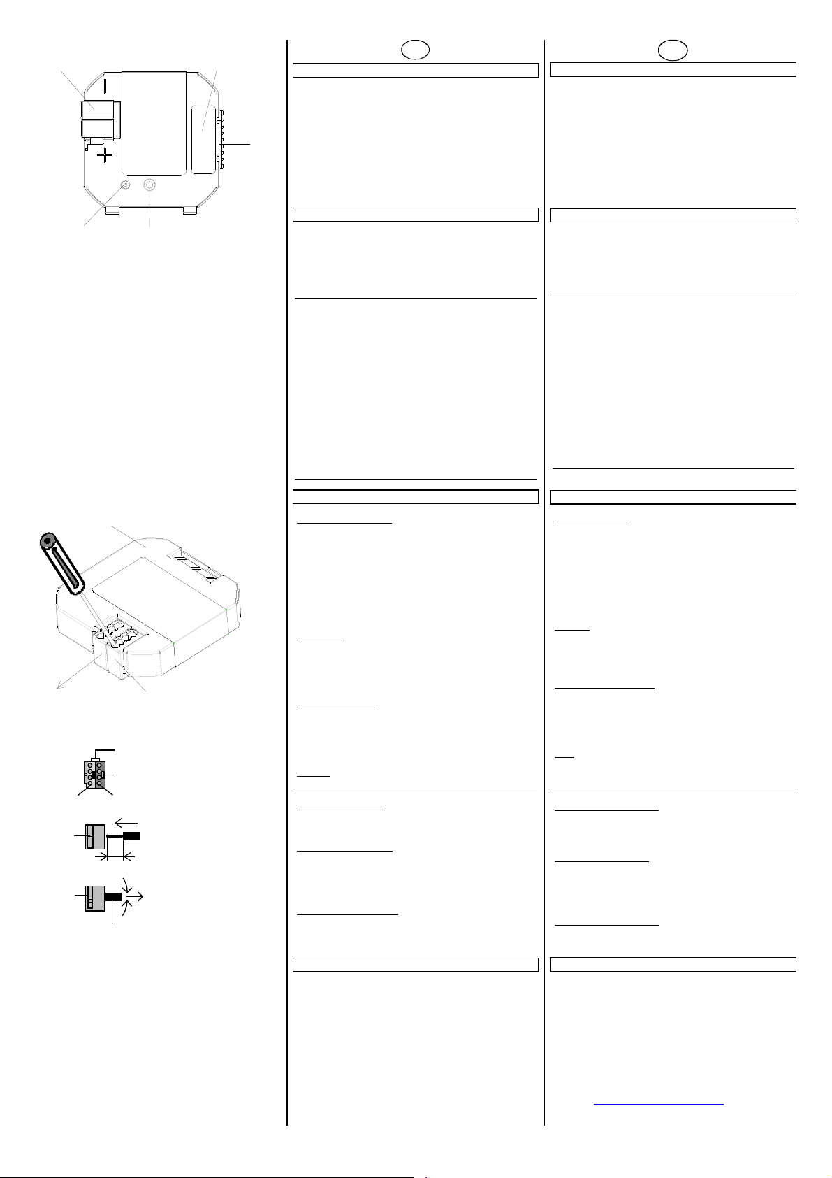
Bild / Figure 2
A3
B1
B2
B2.1
B2
B2
Bild / Figure 3
A5E02551184A DS01 Seite 2 von 2 page 2 of 2
B2
B2.3
B2.2
B2.
5 mm
B2.4
A5
Lage und Funktion der Anzeige- und Bedienelemente
siehe Bild 2
A1 Busklemme für eindrähtige Leiter mit
0,6... 0,8 mm ∅
A2 LED zur Anzeige Normalmodus (LED aus)
oder Adressiermodus (LED ein); sie erlischt automatisch
A4
nach Übernahme der physikalischen Adresse
A3 Lerntaste zum Umschalten zwischen Normalmodus und
Adressiermodus zur Übernahme der
physikalischen Adresse
A4 Anschluss des acht- / vieradrigen Leitungssatzes
A5 Anschlussbild des acht-/ vieradrigen Leitungssatzes
Installationshinweise
• Das Gerät kann für feste Installation in trockenen Innenräu-
men, zum Einbau in UP-Dosen verwendet werden.
WARNUNG
V
• Das Gerät darf nur von einer zugelassenen Elektrofachkraft
installiert und in Betrieb genommen werden.
• Das Gerät darf nicht zusammen mit 230 V Geräten und/oder
230 V Leitungen in derselben Dose eingesetzt werden.
• Das Gerät darf nicht an 230 V angeschlossen werden.
• Gerätekombinationen eines an die Taster-Schnittstelle ange-
schlossenen Tasters mit 230V- Geräten (Steckdose) sind
nicht zulässig.
• Auf sichere Trennung (SELV) der angeschlossenen Signallei-
tungen (einschließlich eventueller Verlängerungen) gegenüber anderen strom-/spannungs-führenden Geräten und Leitungen ist zu achten.
• Die geltenden Sicherheits- und Unfallverhütungsvorschriften
sind zu beachten.
• Das Gerät darf nicht geöffnet werden.
• Bei der Planung und Errichtung von elektrischen Anlagen
sind die einschlägigen Richtlinien, Vorschriften und Bestimmungen des jeweiligen Landes zu beachten.
Montage
Allgemeine Beschreibung
Die Taster- Schnittstelle UP 220/21 oder UP 220/31 wird in Geräteverbindungsdosen (∅ 60mm, 40mm tief) eingelegt. Zusätzlich zur Taster-Schnittstelle kann die Geräteverbindungsdose
noch einen konventionellen Geräteeinsatz aufnehmen. Zur Aufnahme mehrerer konventioneller Geräteeinsätze werden mehrere Geräteverbindungsdosen über Tunnelstutzen kombiniert
(nur die Geräteverbindungsdose zur Aufnahme der TasterSchnittstelle muss 40mm tief sein). Die Adern des mitgelieferten achtadrigen Leitungssatzes können durch die Tunnelstutzen
in die angereihten Geräteverbindungsdosen gelegt werden.
Leitungssatz
Der Leitungssatz besteht aus farblich gekennzeichneten Adern,
die an einem Ende mit einem Stecker fest verbunden sind. Zum
problemlosen Anschluss an die Schraub- oder Steckklemmen
der Schalter / Taster sind die freien Enden mit Aderendhülsen
versehen.
Busklemme abziehen (Bild 3)
- Die Busklemme (B2) besteht aus zwei Teilen (B2.1, B2.2) mit
je vier Klemmkontakten.
- Den Schraubendreher vorsichtig in den Drahteinführungs-
schlitz des grauen Teils der Busklemme (B2.2) einführen und
die Busklemme (B2) aus dem Gerät (B1) herausziehen.
Hinweis
Busklemme nicht von unten heraushebeln! Kurzschlussgefahr!
Busklemme aufstecken
- Die Busklemme in die Führungsnut des Gerätes stecken und
die Busklemme bis zum Anschlag nach unten drücken.
Busleitungen anschließen
- Die Busklemme (B2) ist für eindrähtige Leiter mit
0,6... 0,8 mm ∅ geeignet.
- Den Leiter (B2.4) abisolieren und in Busklemme (B2)
stecken (rot = +, grau = -)
Abklemmen der Busleitung (Bild 3)
- Die Busklemme (B2) abziehen und den Leiter (B2.4) der Bus-
leitung bei gleichzeitigem Hin- und Herdrehen herausziehen.
Allgemeine Hinweise
• Die Bedienungsanleitung ist dem Kunden auszuhändigen.
• Ein defektes Gerät ist mit einem Rücklieferschein der zustän-
digen Vertriebsniederlassung an folgende Adresse zu senden:
SIEMENS AG, Siemensstr. 10, D-93055 Regensburg
• Bei zusätzlichen Fragen zum Produkt wenden Sie sich bitte
an unseren Technical Support:
℡ +49 (0) 180 50 50-222
(0,14 €/Minute aus dem deutschen Festnetz, abweichende
Mobilfunkpreise möglich)
+49 (0) 180 50 50-223
E-Mail: support.automation@siemens.com
www.siemens.de/automation/support-request
(Bild 3)
D
Location and Function of the Display and Operating Elements
see figure 2
A1 Bus terminal for solid conductors with
0.6 ... 0.8 mm ∅
A2 LED for indicating normal operating mode (LED off) or
addressing mode (LED on); it is extinguished automatically once the physical address has been transferred
A3 Learning button for toggling between normal operating
mode and addressing mode for transferring the physical
address
A4 Connection of the eight-/four-core cable set
A5 Circuit diagram of the eight-/four-core cable set
Installation Instructions
The device may be used for permanent interior installations in
dry locations within flush-type boxes.
WARNING
V
• The device must be mounted and commissioned by an
authorised electrician.
• The device must not be mounted in a box
together with 230 V devices and/or 230 V cables.
• The device must not be connected to 230 V.
• Device combinations of a push button connected to the
push button interface and 230 V devices (sockets) are not allowed.
• Ensure that there is a safety separation (SELV) of the con-
nected signal cables (including possible extensions) from the
other current- and voltage-carrying devices and cables.
• The prevailing safety and accident prevention rules must be
heeded.
• The device must not be opened.
• When planning and installing electrical installations, the rele-
vant guidelines, regulations and specifications of the respective country must be observed.
Mounting
General description
The push button interface UP 220/03 or UP 220/13 is built into
in-wall boxes, ∅ 60 mm, depth 40 mm. In addition to the push
button interface, a standard device insert can be attached to the
in-wall box. For mounting several conventional device inserts,
several in-wall boxes must be combined via cable glands (only
the in-wall box that actually holds the push button interface requires a depth of 40 mm). The cores of the eight-core cable set
supplied with the device can be inserted in the seriesconnected in-wall boxes via the cable glands.
Cable set
The cable set consists of cores marked in specific colors with a
plug fixed to one end. To allow for easy connection to the
screw or plug-in terminals of switches and push buttons, ferrules are fixed to the free ends.
Removing the bus terminal (Figure 3)
- The bus terminal (B2) consists of two components (B2.1,
B2.2) with four terminal contacts each.
- Carefully insert the screwdriver in the wire entry slot of the
grey component of the bus terminal (B2.2) and remove the
bus terminal (B2) from the device (B1).
Note
Do not try to remove the bus terminal from underneath! There
is a risk of shorting the device!
Clipping on the bus terminal
- Insert the bus terminal in the guide slot of the push button
interface UP 220/x3 and press the bus terminal downwards
until it reaches the stop.
Connecting the bus cable (Figure 3)
- The bus terminal (B2) can be used with solid conductors,
0.6 ... 0.8 mm ∅.
- Remove the insulation from the conductor (B2.4) and insert it
in the terminal (B2) (red = +, grey = -).
Disconnecting the bus cable (Figure 3)
- Disconnect the bus terminal (B2) and remove the conductor
(B2.4) of the bus cable while twisting it backwards and forwards.
General Notes
• The operating instructions must be handed over to the client.
• A faulty device shall be sent with a Return Good Note for Ser-
vice provided by the appropriate Siemens sales office to the
following address:
SIEMENS AG, Siemensstr. 10, D-93055 Regensburg
• If you have further questions concerning the product please
contact our technical support:
℡ +49 (0) 180 50 50-222
(0,14 €/min. from the German landline network, deviating
mobile communications prices are possible)
+49 (0) 180 50 50-223
E-Mail: support.automation@siemens.com
www.siemens.com/automation/support-request
GB
 Loading...