

Siemens G2255 series Installation Instructions Manual
CE1G2255xx 08.11.2000 1/16
G2255xx
REV22RF
REV-R.01/1
Installationsanleitung Installation instructions
Instructions d’installation Istruzioni di montaggio
Instrucciones de montaje Installatie-aanwijzing
A
B
C
D
E
F

2/16 08.11.2000 CE1G2255xx
G
Fig. 1: DIP-Switch 1…3 und DIP-Switch Reset
DIP-Switch
OPTIMUM P.1
OFF
1h / °C
1/2h / °C
1/4h / °C
123
2252Z01
P.1
DIP-Switch
16...29°C
3...29°C
123
2252Z02
COOLING
HEATING
PUMP ON
PUMP OFF
DIP-Switch
123
PID 12
PID 6
2-Pt
4
2252Z03
5°C
3°C
10°C
Self learning
2252Z03
Fig. 2
t
T
17
18
19
-4
-2
2252D01
16
-3
1/4h/°C
1/2h/°C
1h/°C
P.1
-2
-1
-½
-1½
-1
-½
-¼-¾
P
on
20
°C
T1
-1
h
h
h
TR
x
h
h
h
h
h
h
h
h
h
Platzierungshinweise Regler/Sender REV22RF
• Der Regler/Sender sollte im Hauptaufenthaltsraum
platziert werden (Wandmontage Bild C, freie
Platzierung Bild G)
• Distanz zum Empfänger nicht grösser als 20 m oder 2
Stockwerke
• Der Platzierungsort ist so zu wählen, dass der Fühler
die Lufttemperatur im Raum möglichst unverfälscht
messen kann und nicht durch direkte Sonneneinstrahlung oder andere Wärme- bzw. Kältequellen
beeinflusst wird
• Der Platzierungsort ist so zu wählen, dass ein
möglichst ungestörtes Senden gewährleistet ist. Dazu
sind beim Regler/Sender und beim Empfänger die
gleichen Punkte zu beachten:
− nicht an metallische Oberflächen montieren
− nicht in die Nähe von elektrischen Leitungen, Ge-
räten wie PC’s, Fernseher, Mikrowellengeräte etc.
− nicht im Empfangsschatten von grösseren
Eisenbauteilen, oder baulichen Elementen mit
engmaschigen Metallgittern wie Spezialglas oder
Spezialbeton
Platzierungshinweis bei Wandmontage.
DIP-Switch Reset
DIP-Switch 1
DIP-Switch 3
DIP-Switch 2
CE1G2255xx 08.11.2000 3/16
Inbetriebsetzung Regler / Sender REV22RF
Wir empfehlen zuerst den Empfänger und dann den
Regler/Sender in Betrieb zu nehmen.
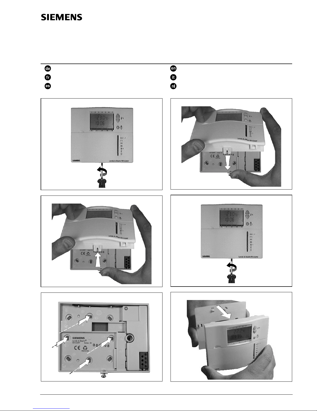
1. Isolierstreifen entfernen
Sobald der schwarze Isolierstreifen am Batteriekontakt
entfernt wird, geht das Gerät in Betrieb.
2. Gerät vom Sockel demontieren
Vorgehen gemäss Bild A und B.
3. Konfiguration mittels DIP-Switches
(Fig. 1)
3.1 Optimierung; DIP-Switch
Durch die Optimierung wird nur der Einschaltzeitpunkt P.1
so vorverschoben, dass der eingestellte Sollwert zur gewünschten Zeit erreicht wird. Die Einstellung ist abhängig
von der Regelstrecke, d.h. von Wärmeübertragung (Rohrleitungsnetz, Heizkörper), Gebäudeverhalten (Masse,
Isolation) und Heizleistung (Kesselleistung, Vorlauftemperatur). Siehe auch Diagramm Fig. 2!
OFF Aus, keine Wirkung (Standard)
¼ h/°C Für schnelle Regelstrecken
½ h/°C Für mittlere Regelstrecken
1 h/°C Für langsame Regelstrecken
Legende zu Fig. 2:
T Temperatur (°C)
t Vorverlegungszeit des Einschaltpunktes (h)
TR
x
Raumtemperatur-Istwert
P
on
Startpunkt Aufheizoptimierung
3.2 Div. Funktionen; DIP-Switch
3.2.1 Sparsollwert-Begrenzung
3…29 °C (Standard)
16…29 °C
3.2.2 Regler-Wirksinn
HEATING Funktion "Heizen" (Standard)
COOLING Funktion "Kühlen"
3.2.3 Periodischer Pumpenlauf (Pumpenkick)
Nur anwendbar bei angesteuerter Umwälzpumpe!
PUMP OFF Funktion aus (Standard)
PUMPON Pumpewirdalle24hum12Uhrfür
jeweils 1 min eingeschaltet.
3.3 Regelverhalten / Frostschutz; DIP-
Switch
3.3.1 Schaltzyklus
Self learning Adaptive Steuerung (Standard):
Für alle Anwendungen.
PID 12 Normale Regelstrecke:
Für Anwendungen an Orten mit
normalen Temperaturschwankungen.
PID 6 Schnelle Regelstrecke:
Für Anwendungen an Orten mit
grossen Temperaturschwankungen.
2-Pt Schwierige Regelstrecke:
Reiner Zweipunktregler mit 0,5 °C
Schaltdifferenz.
3.3.2 Frostschutz
5 °C (Standard)
3 °C oder 10 °C einstellbar
3.4 DIP-Switch Reset (Fig. 1)
Nach Verändern einer DIP-Switch-Position, muss durch
Drücken der Reset-Taste ein DIP-Switch-Reset
durchgeführt werden. Andernfalls ist noch die vorherige
Einstellung aktiv!
4. Gerät wieder auf Sockel montieren
Vorgehen gemäss Bild D und E.
5. Funktionskontrolle
a) Anzeige kontrollieren. Erscheint keine Anzeige muss
der Einbau und die Funktion der Batterien geprüft
werden
b) Wenn bereits das Symbol
(angesteuertes Gerät
EIN) im Display erscheint, wurde damit bereits das
erste Signal zum Empfänger gesendet und der Aufbau
der Kommunikation somit abgeschlossen. Einstellungen
gemäss Bedienungsanleitung vornehmen
c) Erscheint das Symbol
(angesteuertes Gerät EIN)
nicht im Display, muss dieses zuerst für die
Signalübertragung aktiviert werden
d) Frontdeckel aufklappen. Betriebsartenschieber auf
Position
T3 stellen
e) Einstellschieber von AUTO-RUN auf
T3 stellen
f) Bei Wirksinn "Heizen" mit der Plustaste
die
Sollwerttemperatur auf 29 °C stellen.
g) Bei Wirksinn "Kühlen" mit der Minustaste
die
Sollwerttemperatur auf 3 °C stellen.
h) Heizung/Kühlung EIN Symbol
erscheint nach max.
einer Minute im Display
i) Die erste Signalübertragung zum Empfänger ist somit
abgeschlossen
j) Nach 10 Sekunden sendet der Sender erneut ein Signal
k) Das EIN- oder AUS-Signal wird dann alle 20 Minuten
wiederholt. Diese 20 Minuten-Wiederholung wurde aus
Batteriespargründen gewählt
l) Sollwert gemäss e) und f) wieder zurückstellen
m) Betriebsartenschieber wieder auf gewünschte Position
stellen
n) Einstellwahlschieber auf AUTO/RUN stellen.
Die Dauer der Lernbereitschaft des Empfängers beträgt
max 25 Minuten. Wird während dieser Zeit kein Signal vom
Sender empfangen, Schritte d) bis n) nochmals
durchführen.
6. Hinweise
• Sollten im Referenzraum thermostatische Heizkörperventile installiert sein, müssen diese vollständig geöffnet
werden
• Sollte die angezeigte Temperatur nicht mit der effektiv
gemessenen Raumtemperatur übereinstimmen, sollte
der Temperaturfühler neu kalibriert (abgeglichen)
werden (siehe Bedienungsanleitung)
• Die örtlichen Vorschriften für Elektroinstallationen sind
einzuhalten
• Ab Werk sind alle DIP-Switch auf OFF (unten) gestellt
Berichtigte DIP-Switch Einstellungen müssen durch einen
DIP-Switch Reset aktiviert werden.
4/16 08.11.2000 CE1G2255xx
Montagehinweise und Inbetriebsetzung Empfänger REV-R.01/1
H
I
K
L
M
N
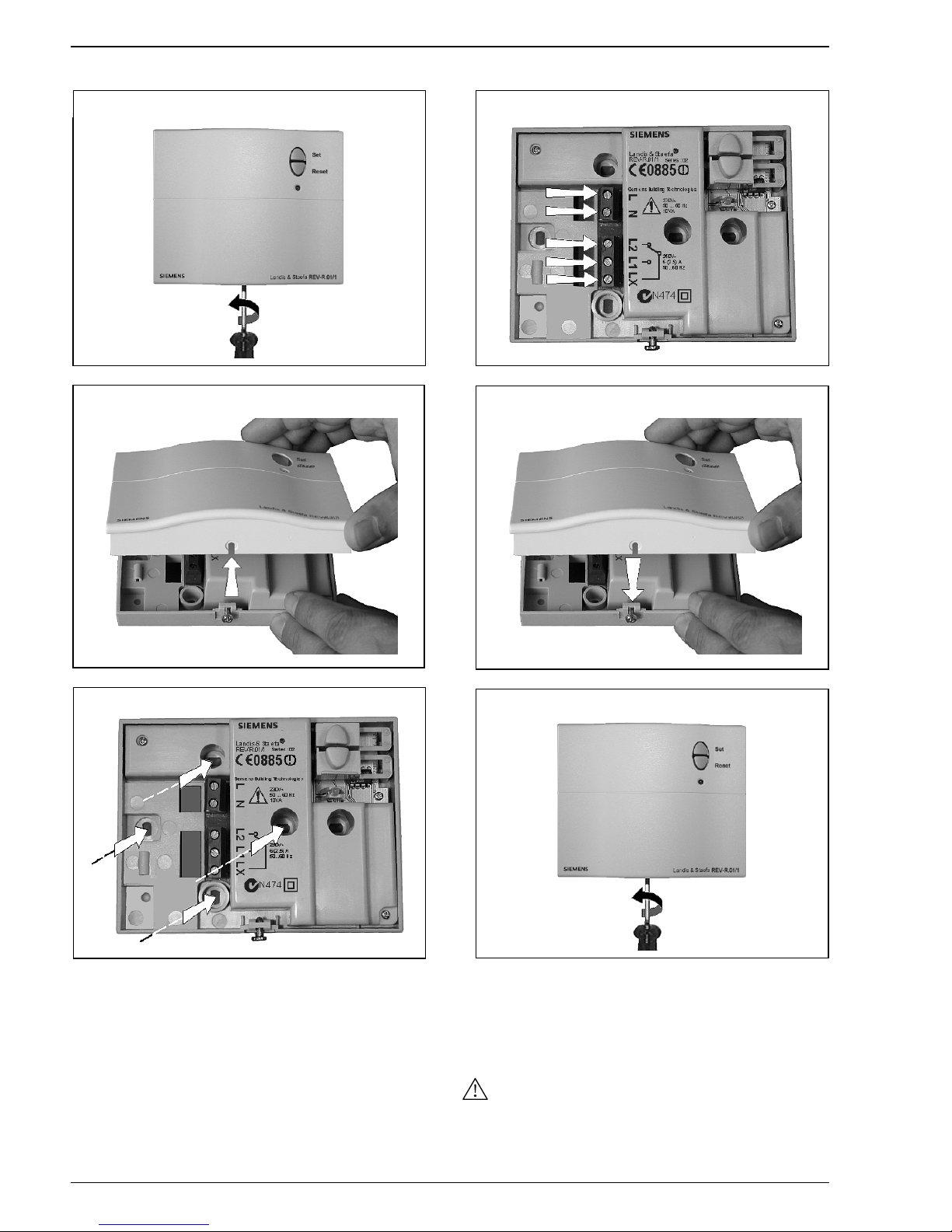
1. Gerät montieren
Vorgehen gemäss Bild H bis N
• Das Empfangs- und Schaltgerät soll vorzugsweise in
der Nähe des Verbrauchers montiert werden
• Der Montageort ist so zu wählen, dass ein möglichst
ungestörter Empfang gewährleistet ist. Dazu sind beim
Regler/Sender und Empfänger die gleichen Punkte zu
beachten:
Liste siehe Platzierungshinweis Regler/Sender
• Auf einen trockenen und spritzwassergeschützten
Standort ist zu achten
• Das Gerät passt auf die meisten handelsüblichen
Unterputzdosen oder wird direkt an die Wand montiert
2. Verdrahtung prüfen
Der Empfänger muss bei ausgeschalteter Netzspannung verdrahtet werden.
Die Netzspannung darf erst nach der fertigen Montage des
Geräts wieder eingeschaltet werden. Die Anschlüsse sind
im Kapitel „Anschlussschaltplan“ ersichtlich
CE1G2255xx 08.11.2000 5/16
3. Inbetriebnahme des Empfängers
Wir empfehlen zuerst den Empfänger und dann den
Regler/Sender in Betrieb zu nehmen.
a) Netz einschalten
b) Taste Reset (= Löschen) für ca. 4 Sekunden drücken,
grüne LED blinkt kurz
(Löschen der gespeicherten Adresse)
c) Taste Set (= Setzen/ lernen) für ca. 3 Sekunden
drücken bis LED grün leuchtet
d) Die Dauer der Lernbereitschaft des Empfängers
beträgt max. 25 Minuten. Wird während dieser Zeit
kein Signal vom Sender empfangen, Schritte b) und c)
nochmals durchführen
e) Regler/Sender montieren und inbetriebsetzen
(siehe Inbetriebsetzung Regler/Sender)
f) Wenn der Empfänger vom Regler/Sender ein Signal
empfängt, blinkt die LED kurz
g) Wenn die LED dauernd leuchtet, ist das Relais
angezogen = angesteuertes Gerät EIN
h) Wenn die LED nicht leuchtet, ist das Relais abgefallen
= angesteuertes Gerät AUS
i) Bei Netzunterbruch am Empfänger wird das Relais auf
AUS geschaltet.
j) Der Sender wiederholt alle 20 Minuten je nach Status
das EIN- oder AUS-Signal.
k) Somit wird spätestens nach 20 Minuten das Relais
wieder entsprechend dem Befehl EIN/AUS
geschaltet
l) Empfängt der REV-R.01/1 während 60 Minuten kein
Signal vom Sender, fällt das Relais ab und schaltet
das angesteuerte Gerät aus
4. Hinweis
• Die örtlichen Vorschriften für Elektroinstallationen sind
einzuhalten
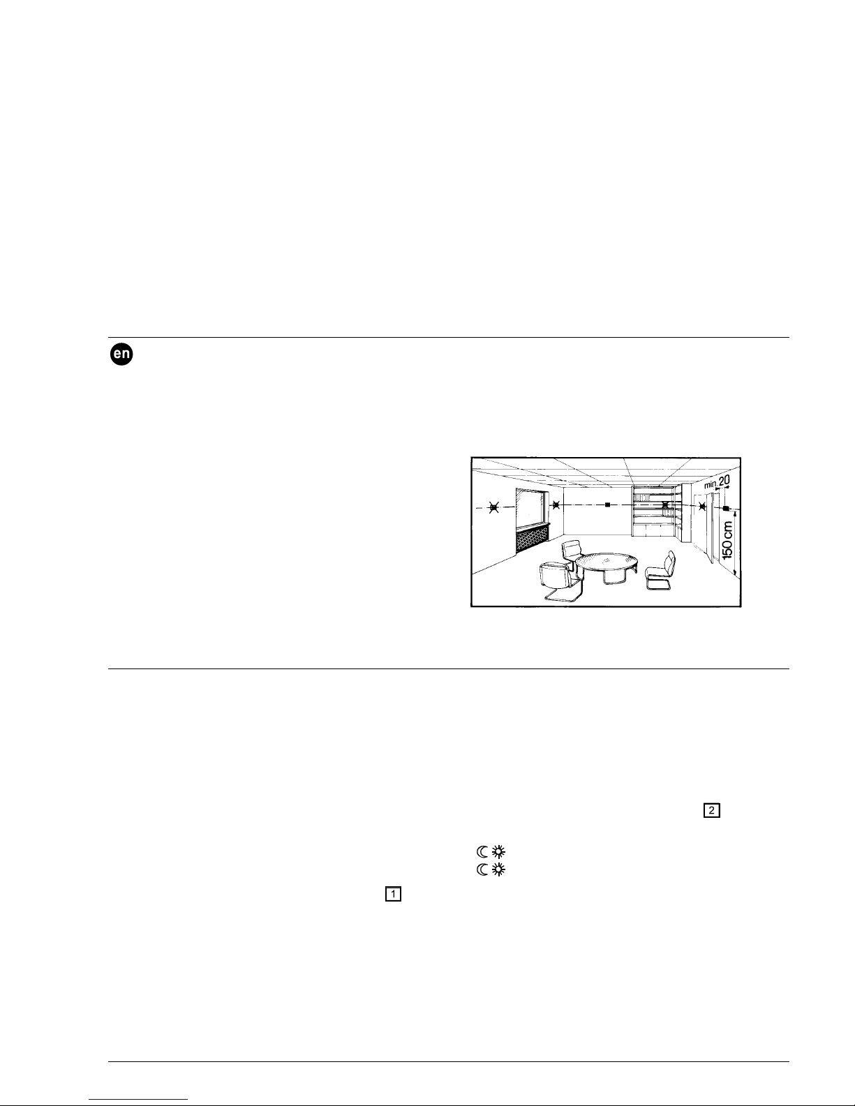
Siting the controller / transmitter REV22RF
• The controller / transmitter should be mounted in the
main living room (wall mounting Fig. C, free standing
Fig. G)
• The distance to the receiver should not exceed 20 m
or 2 floors
• The unit should be located such that it can measure
the room temperature as accurately as possible,
without getting affected by direct solar radiation or
other heat or refrigeration sources
• The unit should be sited so that it can transmit the
signals with as little disturbance as possible. For this
reason, the following points should be observed with
both the controller / transmitter and receiver:
− Do not mount on metal surfaces
− Do not mount near electrical wires, electronic
equipment such as PCs, TV sets, microwave
equipment, etc.
− Do not mount the units in the vicinity of large metal
structures or other construction elements with fine
metal meshes such as special glass or special
concrete
Wall mounting.
Commissioning the controller / transmitter REV22RF
It is recommended to first commission the receiver and
then the controller / transmitter.
1. Remove the battery transit tab
As soon as the battery transit tab is removed, the unit
starts to operate.
2. Remove the unit from its baseplate
Proceed as shown in Figs. A and B.
3. Configuration with the DIP switches
(Fig. 1)
3.1 Optimum start control, DIP switch
Optimum start control brings forward the switch on point
P.1 so that the adjusted setpoint will be reached at the
required time. The setting depends on the type of control
system, that is, on the heat transmission (piping system,
radiators), building dynamics (building mass, insulation)
and heating output (boiler output, flow temperature).
Also refer to Fig. 2!
OFF No effect (standard setting)
¼ h/°C for fast controlled systems
½ h/°C for medium controlled systems
1 h/°C for slow controlled systems
Legend for Fig. 2:
T Temperature (°C)
t Forward shift of switch on point (h)
TR
x
Actual value of room temperature
P
on
Starting point for optimum start control
3.2 Various functions, DIP switch
3.2.1 Limitation of economy setpoint
3…29 °C (standard)
16…29 °C
3.2.2 Operating action of the controller
HEATING Heating mode (standard)
COOLING Cooling mode
3.2.3 Periodic pump run (pump kick)
Can be used only when the circulating pump is controlled!
PUMP OFF Function deactivated (standard)
PUMP ON Pump will be activated for 1 minute
every 24 hours at 12.00.
 Loading...