

Page 1

Date: 2019-12-11 DF MC SNC CSA TCC
- 1 -
Instructions for G120XA FSH-J X9 terminal
How to use the X9 connector which only use in G120XA FSH-J
Tang Huang
Siemens Numerical Control (Nanjing) Co., Ltd., Nanjing
Abstract: When many customers use G120XA FSH-J power section products for
the first time, F7862 alarm will appear after power on operation. Preliminary
inspection shows that there is no obvious abnormality in wiring, and it is impossible
to locate the cause of the problem when they are not familiar with the product.
Keywords:X9,F7862,external fault
1、Fault analysis
Page 2
Date: 2019-12-11 DF MC SNC CSA TCC
- 2 -
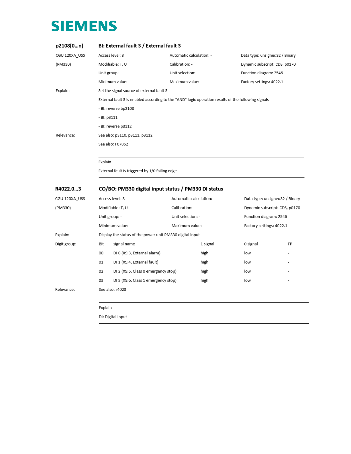
As shown in the figures above, the reason of the appearance of F7862,
according to the user manual of G120XA, is that the input signal of the
signal source r402.1 of external fault 3 is low, and the state of r4022.0~3 is
controlled by X9 terminal. Therefore, when F7862 fault occurs, it is
necessary to confirm whether X9 terminal has been correctly connected!
2、X9 terminal
1. Mechanical installation of G120XA FAH-J X9 terminal
Page 3

Date: 2019-12-11 DF MC SNC CSA TCC
- 3 -
2. G120XA FAH-J X9 terminal function
Terminal strip X9 is used to connect external 24V DC power supply and
main contactor or bypass contactor.
To connect the terminal strip X9, remove the front cover of the converter. Its
DIs can be connected with fault signal and alarm signal.
When the converter is connected to the power supply through the main
contactor, it is necessary to connect the external 24V DC power supply.
The power supply must be near the converter (such as in the same control
cabinet), and the cable length to terminal block X9 shall not exceed 5
meters.
Terminal
Name
meaning
Input/output
Technical data
1
P24
External
power
supply
Input
Voltage:24V DC(20.1V
~28.8V)
Current consumption: 2A
maximum
2 M Electronic
grounding
Reference
3
External
External
Input
Voltage: -3V ...+30V
Page 4

Date: 2019-12-11 DF MC SNC CSA TCC
- 4 -
alert
alarm
Current consumption:
✓ 6.4 mA at 24V DC
✓ 1.3 mA when < 5V
✓ 4 mA when > 15V
✓ 8 mA at 30V
Level (including waviness):
✓ High level:15V ...30V
✓ Low level:-3V ...+5V
4
External
fault
External
fault
Input
5
Stop 0
Emergency
OFF,
category 0
Input
6
Stop 1
Emergency
stop
category 1
Input
7 M
Reference
8
DC link
charged
Enable
signal, “U”
DC link
charged
Output
Voltage:24V DC
Maximum load current: 500mA
Continuous short circuit
protection
The output current is taken from
the power supply via X9
terminal
9
NC
Not
connected
10
NC
Not
connected
11
Activation
line
contactor
Line
contactor
control
Output
Contact type: NO contact
Maximum load current: 4A,
230V AC,cosφ = 0.6ind
Floating potential
For feeders with contactless
outputs (e.g.4A/250V fuses), a
protection device is required to
prevent overload and short
circuit.
The overvoltage limiter must be
connected to the excitation coil
of the main contactor (e.g. RC
circuit).
The following relay contact
characteristic values are
applicable to the control of the
main contactor:
✓ 250V AC,10A(NC and
NO)currency, 85℃
✓ 24V DC, 10A(NC and
NO), currency, 85℃
✓ 30V DC,8A(NO)、6A
(NC), currency, 85℃
✓ B300(NC and NO),
general purpose,85℃
✓ R300(NC and NO),
general purpose, 85℃
✓ 24V AC, 2.0A(NC and
NO), general purpose,
12
Activation
Line
contactor
Line
contactor
control
Output
Page 5

Date: 2019-12-11 DF MC SNC CSA TCC
- 5 -
85℃
Note:
1)The input is low level active
All signal inputs are low level active (anti break).
2)Terminal 3~6 not used
When terminal 3~6 is not in use, DC 24V must be applied. To do this, use an external
power supply or terminal 9 on the control unit. Terminal 2 and 7 with reference potential
X9 and terminal 28 on the control unit. Refer to terminals 2 and 7 with potential X9 and
terminal 28 on the control unit.
3)Main contactor control
When power is supplied to the main contactor via terminals 11 and 12, it is not necessary
to disconnect from the power supply system via the control transformer. 250V/8A fuse
must be used as protection measure.
4)Strain relief
The cables for the control unit and terminal X9 must be fixed to the terminal block in the
cable channel under terminal X9 for strain relief. If the cable is introduced into the cable
channel from the side (at the height of terminal X9), the strain relief must be performed
outside the power module.
5)Wiring standard
Maximum connection cross section: 2.5 mm²(14AWG)
Minimum connection cross section: 0.2 mm²(25AWG)
Maximum tightening torque: 0.5 Nm (4.4 lbf.in)
3、Troubleshooting
1. According to the actual use requirements, the wiring should be correct to
ensure that r4022.03 input is high when there is no abnormal external
alarm/alarm and emergency stop signal.
2. If the current hardware wiring cannot be completed, the alarm can be
shielded by setting parameters. Since pins 3 to 6 on X9 terminal correspond
to external alarm 3, external fault 3, emergency stop category 1 and
emergency stop category 2 respectively, all the 4 corresponding bic0
parameters need to be set high. The specific settings are as follow:
parameter
meaning
Default
value
Setting
value
P2117.0
BI: set the signal source of external alarm 3.
r4022.0
1
P2108.0
BI: set the signal source of external fault 3.
r4022.1
1
P849.0
BI: no fast stop/ fast stop (OFF3) signal source 2/
r4022.2
1
Page 6

Date: 2019-12-11 DF MC SNC CSA TCC
- 6 -
OFF3 signal source 2
P845.0
BI: without slow stop/ slow stall (OFF2) signal
source 2
r4022.3
1
 Loading...