

Page 1

Technical documentation /
SINAMICS GX
Available in power ratings up to hp ( kW)
usa.siemens.com/sinamics-gx
Page 2
SINAMICS GX
An infrastructure drive for pumps, fans and compressors
Siemens introduces an exciting new addition to the existing SINAMICS
product portfolio — the GX — an “infrastructure” drive up to hp
(kW), which is targeted for pump, fan and compressor applications in
the water / wastewater, HVAC, irrigation / agriculture and industrial chiller
and refrigeration industries.
Seamless process for higher efficiency
SINAMICS G120X is simple, seamless, cost- and energy-efficient, robust, reliable and fit
for digitalization. It integrates easily into existing applications, works with any standard
motor (induction, synchronous and synchronous reluctance) and can be configured for
cost-optimization and resource-saving operation which ultimately helps reduce total cost of
ownership. SINAMICS G120X meets all the latest industry standards with regard to energy
efficiency and product safety, and offers enhanced safety with SIL3-rated safety functions
and up to 100kA short-circuit current rating according to new UL61800-5-1 design.
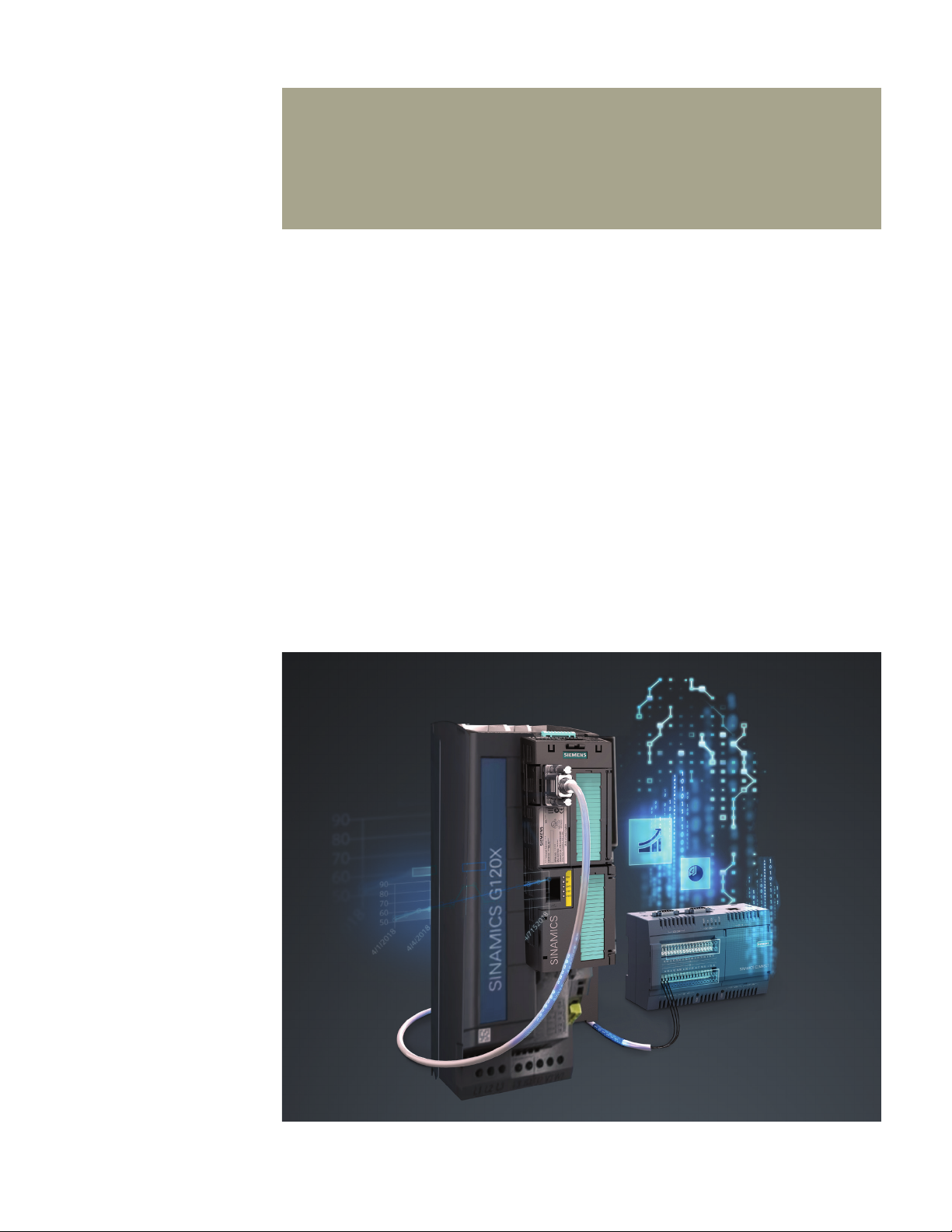
SINAMICS G120X with
SINAMICS Connect 300
for MindSphere connectivity
2
Page 3

Technical data
Line voltage and output power range
FSA…FSF
FSA…FSG
FSH, FSJ 3AC 380V (-15%)…480V (+10%) 400 hp…700 hp (315kW…560kW)
FSD…FSG 3AC 500V (-20%)…690V (+10%) 4 hp…250 hp (3kW…250kW)
FSH, FSJ 3AC 500V (-15%)…690V (+10%) 350 hp…700 hp (315kW…630kW)
Output voltage
Input frequency
Output frequency
FSA…FSG
FSH, FSJ 0 Hz…150 Hz (depending upon the control mode)
Fundamental power factor (Cos φ)
Efficiency class
Efficiency (η)
3AC 200V (-20%)…240V (+10%) 1 hp…75 hp (0.75kW…55kW)
3AC 380V (-20%)…480V (+10%) 1 hp…400 hp (0.75kW…250kW)
3AC 0V….line voltage x 0.97
47 Hz…63 Hz
0 Hz…550 Hz (depending upon the control mode)
0.96…0.99
IE2 (Based on power losses according to EN 50598-2 and IEC 61800-9-2)
98%
Motor control
Supported motor types
Degree of protection
Operating temperature
n
V/Hz control (linear, linear with flux current control / FCC, parabolic and eco mode)
n
Sensorless less vector control (SLVC)
n
Asynchronous (induction) motor
n
Permanent magnet synchronous motor (PMSM)
n
Synchronous reluctance motor (SRM)
IP20 / UL Open Type
-4° F to 113° F (-20° C to 45° C) without derating
> 113° F up to 140° F (> 45° C up to 60° C) with derating
For PROFINET, EtherNet / IPTM up to 55° C (131° F) with derating
3
Page 4

Overload
Low Overload (LO) / Variable Torque (VT) 110% x IL for 60s
High Overload (HO) / Constant Torque (CT) 150% x IH for 60s
Communication
Functional safety
Short-circuit current rating (SCCR)
PROFINET, EtherNet / IPTM, USS, Modbus RTU, BACnet MS / TP, PROFIBUS DP
Hardware-based SIL3 Safe Torque Off (STO) function with on / off switch
Up to 100kA according to NEW UL 61800-5-1 design
Control inputs and outputs
6 Digital Inputs (DI 0 … DI 5) 24V (12–30V) electrically isolated, 4mA current, PNP / NPN switchable
2 Digital (Relay) Outputs (DO 0…DO 1) Type C, 250V AC, 2A / 30V DC, 2A for resistive, inductive or capacitive load
2 Analog Inputs (AI 0…AI 1)
Differential input 0V… 10V or -10V … +10V: typical current drain: 0.1 mA,
max. voltage 35V
0/4 mA ... 20 mA: 120 input resistance, voltage < 10V, current < 80 mA
1 Analog Output (AO 0)
Not isolated, switchable between voltage (0V… 10V) and current
(0/4 mA ... 20 mA) via parameter setting
1 motor temperature sensor input PTC, KTY, PT1000, bi-metallic switch with normally closed contact
1 failsafe digital input STO — electrically isolated
1 internal aux. supply voltage
24V DC, max. 250 mA
10V DC, max. 10 mA
1 external aux. supply voltage 24V DC (20.4 … 28.8V DC), current consumption 0.5A
1 memory card slot For optional SD memory cards (as a backup storage device for saving of the settings
after drive commissioning, and also for a series commissioning of a several identical
drives via cloning of the settings)
Additional control inputs and outputs (With optional I/O Extension Module)
2 Digital Inputs (DI 6…DI 7)
24V (12–30V) electrically isolated, 4mA current, PNP / NPN switchable
4 Digital (Relay) Outputs (DO 2…DO 5) 2x Type A and 2x Type C relay outputs rated 250V AC, 2A / 30V DC, 2A for resistive,
inductive or capacitive load
1 Analog Input (AI 2) Analog current input (0/4 mA … 20 mA) or Temperature sensor input
(Pt10000 / LG-Ni10000 / DIN-Ni1000)
1 motor temperature sensor input (AI 3) Temperature sensor input (Sensor Pt10000 / LG-Ni10000 / DIN-Ni1000)
2 Analog Output (AO 1 … AO 2) Not isolated, switchable between voltage (0V… 10V) and current (0/4 mA ... 20 mA)
via parameter setting
User interface
Standard
Intelligent Operator Panel (IOP-2) — a high-resolution graphical color keypad
Optional Smart Access Module (SAM) Part number: 6SL3255-0AA00-5AA0 — a WiFi-based
web server module and engineering tool for quick setup and diagnostics using
a mobile device (PC, smartphone, tablet, etc.)
Basic Operator Panel (BOP-2) — a basic keypad
Blank (no Operator Panel / keypad)
4
Page 5

SINAMICS GX
It’s the simple, seamless and easy-to-use drive —
right out of the box.
Digitalization and IoT based secured health monitoring
SINAMICS CONNECT 300
Certification / marking
and
Analyze MyDrives
SINAMICS CONNECT 300 (Part number: 6SL3255-0AG30-0AA0) is the IoT gateway.
It is designed to acquire data through the serial port of the SINAMICS G120X
and synchronize the data to MindSphere (cloud-based open IoT operating system
of Siemens) using the MindSphere application Analyze MyDrives (AMD).
This offers users the opportunity to analyze valuable operating data gathered
from the drive and enables the visualization and analysis of status information,
providing users with valuable data which can be used as the basis for process
optimization and maintenance strategies.
For more information visit: www.siemens.com/sinamics-digitalization
n
CULUS marking according to UL61800-5-1 and CSA C22.2 No. 274 with SCCR up
to 100kA
n
CE marking according to European Low-Voltage Directive 2014/35/EU EU and IEC/
EN 61800-5-1, Machinery directive 2006/42/EC and IEC/EN 61800-5-2, EMC
Directive 2014/30/EU and IEC/EN 61800-3, RoHS directive 2011/65/EU and EN
50581
n
IE2 efficiency level based on power losses according to EN 50598-2 and
IEC 61800-9-2
n
Safe torque off (STO) SIL3 rating according to IEC/EN 61800-5-2
n
EAC, K, RCM (formerly C-Tick), REACH, RoHS II, SEMI F47
5
Page 6

Application functions
Pump-specific
n
Deragging or blockage protection
n
Pipe filling
n
Multi-pump control
n
Pump switchover
n
Stop mode
n
Service mode
n
Cascade control mode
n
Blockage, leakage and dry-running protection
n
Cavitation protection
n
Condensation protection
n
Frost protection
Fan-specific
n
Flying restart
n
Automatic restart
n
Skip frequency bands
n
Fire mode (essential service mode)
n
No load, torque and rotation (belt) monitoring with sensor
Increase energy efficiency and system performance
n
Eco mode
n
Hibernation or sleep mode
n
Bypass mode
n
Energy / flow calculator
n
Support to high efficiency motors (PMSM and SRM)
n
Real time clock and programmable timer (3)
Optimize pump and fan operation and increase system availability
n
Keep running mode
n
PID controller
Protection functions
n
Phase-loss detection for both supply and motor
n
Overvoltage controller
n
Undervoltage controller
n
Drive overtemperature protection
n
Loss of analog input signal monitoring
n
External fault and warning monitoring (up to 3)
n
Motor overtemperature protection (with and without sensor)
n
Dual ramp
n
Motor overload monitoring and protection
n
Motor short-circuit and ground fault protection
n
Speed and torque monitoring
n
Blocking and stalling monitoring and protection
n
Detection of missing communication telegrams
n
Detection of communication bus interruption
n
Multi-speed setpoints
6
Page 7

SINAMICS G120X — dimensions and clearance distances FSA...FSJ
Additional depth
D
H
W
Dimensions Max. weight of frame
Frame
size
H
mm (inch)
W
mm (inch)
D
mm (inch)
FSA 232 (9.1) 73 (2.9)
FSB 275 (10.8) 100 (3.9) 5.8 (12.8) 6.2 (13.7)
209 (8.2)
Additional depth
with Operator Panel
mm (inch)
No filter
kg (lbs)
1
With filter
kg (lbs)
3.4 (7.5) 3.6 (8)
FSC 295 (11.6) 140 (5.5) 7.11 (15.7) 7.7 (17)
FSD 472 (18.6) 200 (7.9)
9 (0.4)
18.8 (41.5) 19.5 (43)
239 (9.4)
FSE 551 (21.7) 275 (10.8) 26.7 (59) 28.7 (63.3)
FSF 709 (27.9) 305 (12)
66.5 (146.6) 71 (156.53)
360 (14.2)
FSG 999.4 (39.3) 305 (12)
FSH 1696 (66.8) 548 (21.6)
–
120 (264.6)
162 (357.2)
393 (15.5) –
FSJ 1621 (63.8) 801 (31.5) 250 (551.16)
1
Refer to SINAMICS G120X operating instructions or rating plate information of a unit to obtain the weight specific to each rating / order number
1
7
Page 8

SINAMICS G120X — Selection and ordering data
Voltage class 3AC 200...240V, 47...63Hz
Frame size kW (200V) hp (240V)
0.75 1 4.2 6 S L 3 2 0 – Y C 1 0 – U 0
FSA
FSB
FSC
FSD
FSE
FSF
1.1 1.5 6 6 S L 3 2 0 – Y C 1 2 – U 0
1.5 2 7.4 6 S L 3 2 0 – Y C 1 4 – U 0
2 3 10.4 6 S L 3 2 0 – Y C 1 6 – U 0
3 4 13.6 6 S L 3 2 0 – Y C 1 8 – U 0
4 5.0 17.5 6 S L 3 2 0 – Y C 2 0 – U 0
5.5 7.5 22 6 S L 3 2 0 – Y C 2 2 – U 0
7.5 10 28 6 S L 3 2 0 – Y C 2 4 – U 0
11 15 42 6 S L 3 2 0 – Y C 2 6 – U 0
15 20 54 6 S L 3 2 0 – Y C 2 8 – U 0
18.5 25 68 6 S L 3 2 0 – Y C 3 0 – U 0
22 30 80 6 S L 3 2 0 – Y C 3 2 – U 0
30 40 104 6 S L 3 2 0 – Y C 3 4 – U 0
37 50 130 6 S L 3 2 0 – Y C 3 6 – U 0
45 60 154 6 S L 3 2 0 – Y C 3 8 – U 0
55 75 192 6 S L 3 2 0 – Y C 4 0 – U 0
Special coating according to IEC/EN 60721-3-3
Class 3C2 (Standard)
Class 3C3
*
User interface
Blank (No operator panel / keypad)
BOP-2 (Basic keypad, Class 3C3*)
IOP-2 (Standard — high-resolution graphical color keypad, Class 3C3*)
I / O extension module
without I/O extenstion module
with I/O extenstion module, Class 3C3
EMC class
No EMI / RFI filter
Communication interface
PROFINET, EtherNet / IP™ (Standard)
USS, Modbus, RTU, BACnet MS / TP
PROFIBUS DP
*
Special coating or sealing for operation in harsh / corrosive environments
Rated Output Current
IL, A (240V)
*
Order number
2
3
1
2
3
0
1
U
F
B
P
8
Page 9

SINAMICS G120X — Selection and ordering data
Voltage class 3AC 380...480V, 47...63Hz
Frame size kW (400V) hp (480V)
0.75 1 2.1 6 S L 3 2 0 – Y E 1 0 – 0
1.1 1.5 3 6 S L 3 2 0 – Y E 1 2 – 0
FSA
FSB
FSC
FSD
FSE
FSF
FSG
FSH
FSJ
1.5 2 3.4 6 S L 3 2 0 – Y E 1 4 – 0
2.2 3 4.8 6 S L 3 2 0 – Y E 1 6 – 0
3 4 6.2 6 S L 3 2 0 – Y E 1 8 – 0
4 5 7.6 6 S L 3 2 0 – Y E 2 0 – 0
5.5 7.5 11 6 S L 3 2 0 – Y E 2 2 – 0
7.5 10 14 6 S L 3 2 0 – Y E 2 4 – 0
11 15 21 6 S L 3 2 0 – Y E 2 6 – 0
15 20 27 6 S L 3 2 0 – Y E 2 8 – 0
18.5 25 34 6 S L 3 2 0 – Y E 3 0 – 0
22 30 40 6 S L 3 2 0 – Y E 3 2 – 0
30 40 52 6 S L 3 2 0 – Y E 3 4 – 0
37 50 65 6 S L 3 2 0 – Y E 3 6 – 0
45 60 77 6 S L 3 2 0 – Y E 3 8 – 0
55 75 96 6 S L 3 2 0 – Y E 4 0 – 0
75 100 124 6 S L 3 2 0 – Y E 4 2 – 0
90 125 156 6 S L 3 2 0 – Y E 4 4 – 0
110 150 180 6 S L 3 2 0 – Y E 4 6 – 0
132 200 240 6 S L 3 2 0 – Y E 4 8 – 0
160 250 302 6 S L 3 2 0 – Y E 5 0 – 0
200 300 361 6 S L 3 2 0 – Y E 5 2 – 0
250 400 477 6 S L 3 2 0 – Y E 5 4 – 0
315 400 477 6 S L 3 2 2 0 – Y E 5 6 – C 0
355 450 515 6 S L 3 2 2 0 – Y E 5 8 – C 0
400 500 590 6 S L 3 2 2 0 – Y E 6 0 – C 0
450 500 663 6 S L 3 2 2 0 – Y E 6 2 – C 0
500 600 724 6 S L 3 2 2 0 – Y E 6 4 – C 0
560 700 830 6 S L 3 2 2 0 – Y E 6 6 – C 0
Special coating according to IEC/EN 60721-3-3
Class 3C2 (Standard)
Class 3C3
*
User interface
Blank (No operator panel / keypad)
BOP-2 (Basic keypad, Class 3C3*)
IOP-2 (Standard — high-resolution graphical color keypad, Class 3C3*)
I / O extension module
without I/O extenstion module
with I/O extenstion module, Class 3C3
EMC class
No filter (Standard — without integrated EMI / RFI filter) for FSA to FSF only
Filter C2 (With integrated EMI / RFI filter Category C2) for FSA to FSG only, see Note 1
Filter C3 (Standard — with integrated EMI / RFI filter Category C3) for FSG to FSJ only, see Note 1
Communication interface
PROFINET, EtherNet / IP™ (Standard)
USS, Modbus, RTU, BACnet MS / TP
PROFIBUS DP
*
Special coating or sealing for operation in harsh / corrosive environments
Rated Output Current
IL, A (480V)
*
Order number
2
3
1
2
3
0
1
U
A
C
F
B
P
Note 1: For frame sizes FSG, FSH and FSJ, the filter can be deactivated by removing a grounding screw / clip for applications in an ungrounded or
a high-resistance grounded or a corner-grounded supply system. Please refer to the SINAMICS G120X Operating Instructions for more information.
9
Page 10

SINAMICS G120X — Selection and ordering data
Voltage class 3AC 500...690V, 47...63Hz
Frame size kW (690V) hp (600V)
3 4 5 6 S L 3 2 0 – Y H 1 8 – 0
4 5 6.3 6 S L 3 2 0 – Y H 2 0 – 0
5.5 7.5 9 6 S L 3 2 0 – Y H 2 2 – 0
7.5 10 11 6 S L 3 2 0 – Y H 2 4 – 0
FSD
FSE
FSF
FSG
FSH
FSJ
11 10 14 6 S L 3 2 0 – Y H 2 6 – 0
15 15 19 6 S L 3 2 0 – Y H 2 8 – 0
18.5 20 23 6 S L 3 2 0 – Y H 3 0 – 0
22 25 27 6 S L 3 2 0 – Y H 3 2 – 0
30 30 35 6 S L 3 2 0 – Y H 3 4 – 0
37 40 42 6 S L 3 2 0 – Y H 3 6 – 0
45 50 52 6 S L 3 2 0 – Y H 3 8 – 0
55 60 62 6 S L 3 2 0 – Y H 4 0 – 0
75 75 80 6 S L 3 2 0 – Y H 4 2 – 0
90 100 100 6 S L 3 2 0 – Y H 4 4 – 0
110 125 125 6 S L 3 2 0 – Y H 4 6 – 0
132 150 144 6 S L 3 2 0 – Y H 4 8 – 0
160 150 171 6 S L 3 2 0 – Y H 5 0 – C 0
200 200 208 6 S L 3 2 0 – Y H 5 2 – C 0
250 250 250 6 S L 3 2 0 – Y H 5 4 – C 0
315 350 345 6 S L 3 2 2 0 – Y H 5 6 – C 0
355 400 388 6 S L 3 2 2 0 – Y H 5 8 – C 0
400 450 432 6 S L 3 2 2 0 – Y H 6 0 – C 0
450 500 487 6 S L 3 2 2 0 – Y H 6 2 – C 0
500 500 546 6 S L 3 2 2 0 – Y H 6 4 – C 0
560 600 610 6 S L 3 2 2 0 – Y H 6 6 – C 0
630 700 679 6 S L 3 2 2 0 – Y H 6 8 – C 0
Special coating according to IEC/EN 60721-3-3
Class 3C2 (Standard)
Class 3C3
*
User interface
Blank (No operator panel / keypad)
BOP-2 (Basic keypad, Class 3C3*)
IOP-2 (Standard — high-resolution graphical color keypad, Class 3C3*)
I / O extension module
without I/O extenstion module
with I/O extenstion module, Class 3C3
EMC class
No filter (Standard — without integrated EMI / RFI filter) for FSD to FSF only
Filter C2 (With integrated EMI / RFI filter Category C2) for FSD to FSE only
Filter C3 (With integrated EMI / RFI filter Category C3) for FSF to FSJ only, standard for FSG to FSJ, see Note 1
Communication interface
PROFINET, EtherNet / IP™ (Standard)
USS, Modbus, RTU, BACnet MS / TP
PROFIBUS DP
*
Special coating or sealing for operation in harsh / corrosive environments
Rated Output Current
IL, A (600V)
*
Order number
2
3
1
2
3
0
1
U
A
C
F
B
P
10
Note 1: For frame sizes FSG, FSH and FSJ, the filter can be deactivated by removing a grounding screw / clip for applications in an ungrounded or
a high-resistance grounded or a corner-grounded supply system. Please refer to the SINAMICS G120X Operating Instructions for more information.
Page 11

SINAMICS G120X IP20 Push-Through kits
FSA–FSC with PT kit
SINAMICS
G120X
Push-Through kit
(PT)
Width mm (inch) Height mm (inch) Depth mm (inch)
Frame size Part number W
Overall dimensions of SINAIMCS G120X with PT kit installed
H = with
shield plate
H1= without
shield plate
FSD–FSG with PT kit
T1 = front
of PT bracket
FSA 6SL3261-6GA00-0BA0 127 (5.0) 324 (12.8) 234 (9.2) 160 (6.3) 57 (2.2)
FSB 6SL3261-6GB00-0BA0 154 (6.1) 384 (15.1) 279 (11.0) 153 (6.0) 66 (2.6)
FSC 6SL3261-6GC00-0BA0 192 (7.6) 407 (16.0) 295 (11.6) 154 (6.1) 65 (2.6)
FSD 6SL3261-6GD00-0BA0 271 (10.7) 647 (25.5) 514 (20.2) 142 (5.6) 98 (3.9)
FSE 6SL3261-6GE00-0BA0 360 (14.2) 773 (30.4) 600 (23.6) 145 (5.7) 93 (3.7)
FSF 6SL3261-6GF00-0BA0 396 (15.6) 1003 (39.5) 749 (29.5) 185 (7.3) 185 (7.3)
FSG 6SL3261-6GG00-0BA0 384 (15.1) 1275 (50.2) 1026 (40.4) 184 (7.3) 188 (7.4)
SINAMICS G120X — options and features
T2 = back
of PT bracket
Options
n
Special coating (Class 3C3) for operation of a drive in
the harsh environments where corrosive gases for
example, Hydrogen Sulfide (H2S), Chlorine (Cl) or
Ammonia (NH3) are often present
n
Add-on Push-Through (PT) kit to enable UL Open
Type / IP20 drive in
to UL Open Type / IP20 push-through drive (up to FSG)
n
Input and output reactors
n
Output du / dt filter
n
Output Sinusoidal filter
n
Passive line harmonic filter
n
EMI / RFI filters
n
Communication: PROFINET, EtherNet / IP™, USS,
Modbus RTU, BACnet MS / TP and PROFIBUS DP
n
I/O extension module
11
Page 12

Discover the new SINAMICS G120X
usa.siemens.com/sinamics-g120x
Published by
Siemens Industry, Inc.
Triangle Parkway, Suite
Norcross, GA
() -
Order No. DRTD-GX-
Printed in USA
© Siemens Industry, Inc.
usa.siemens.com/motioncontrol
This brochure contains only general descriptions or performance features,
which do not always apply in the manner described in concrete application
situations or may change as the products undergo further development.
Performance features are valid only if they are formally agreed upon when
the contract is closed.
Siemens is a registered trademark of Siemens AG. Product names mentioned
may be trademarks or registered trademarks of their respective companies.
Specifications are subject to change without notice.
 Loading...