

Page 1
___________________
___________________
___________________
___________________
___________________
SINAMICS
SINAMICS G120P
CU230P-2 Control Units
Compact Operating Instructions
Edition 01/2017
01/2017
A5E38815802B AA
Fundamental safety
instructions
1
Scope of delivery
2
Installing
3
Commissioning
4
More information
5
Page 2

Siemens AG
Division Digital Factory
Postfach 48 48
90026 NÜRNBERG
GERMANY
A5E38815802B AA
Ⓟ
Copyright © Siemens AG 2015 - 2017.
All rights reserved
Legal information
Warning notice system
DANGER
indicates that death or severe personal injury will result if proper precautions are not taken.
WARNING
indicates that death or severe personal injury may result if proper precautions are not taken.
CAUTION
indicates that minor personal injury can result if proper precautions are not taken.
NOTICE
indicates that property damage can result if proper precautions are not taken.
Qualified Personnel
personnel qualified
Proper use of Siemens products
WARNING
Siemens products may only be used for the applications described in the catalog and in the relevant technical
maintenance are required to ensure that the products operate safely and without any problems. The permissible
ambient conditions must be complied with. The information in the relevant documentation must be observed.
Trademarks
Disclaimer of Liability
This manual contains notices you have to observe in order to ensure your personal safety, as well as to prevent
damage to property. The notices referring to your personal safety are highlighted in the manual by a safety alert
symbol, notices referring only to property damage have no safety alert symbol. These notices shown below are
graded according to the degree of danger.
If more than one degree of danger is present, the warning notice representing the highest degree of danger will
be used. A notice warning of injury to persons with a safety alert symbol may also include a warning relating to
property damage.
The product/system described in this documentation may be operated only by
task in accordance with the relevant documentation, in particular its warning notices and safety instructions.
Qualified personnel are those who, based on their training and experience, are capable of identifying risks and
avoiding potential hazards when working with these products/systems.
for the specific
Note the following:
documentation. If products and components from other manufacturers are used, these must be recommended
or approved by Siemens. Proper transport, storage, installation, assembly, commissioning, operation and
All names identified by ® are registered trademarks of Siemens AG. The remaining trademarks in this publication
may be trademarks whose use by third parties for their own purposes could violate the rights of the owner.
We have reviewed the contents of this publication to ensure consistency with the hardware and software
described. Since variance cannot be precluded entirely, we cannot guarantee full consistency. However, the
information in this publication is reviewed regularly and any necessary corrections are included in subsequent
editions.
01/2017 Subject to change
Page 3

Table of contents
1 Fundamental safety instructions .............................................................................................................. 4
2 Scope of delivery .................................................................................................................................... 6
3 Installing ................................................................................................................................................. 7
4 Commissioning ..................................................................................................................................... 33
5 More information ................................................................................................................................... 49
What is the meaning of the symbols in the manual?
1.1 General safety instructions ....................................................................................................... 4
1.2 Industrial security ...................................................................................................................... 5
3.1 Plugging the Control Unit onto the Power Module .................................................................... 7
3.2 Overview of the interfaces ...................................................................................................... 10
3.3 Terminal strips ........................................................................................................................ 12
3.4 Factory interface settings ........................................................................................................ 14
3.5 Default setting of the interfaces .............................................................................................. 16
4.1 Tools to commission the converter ......................................................................................... 33
4.2 Commissioning with BOP-2 operator panel ............................................................................ 34
4.2.1 Start quick commissioning and select the application class ................................................... 34
4.2.2 Identifying the motor data and optimizing the closed-loop control ......................................... 38
4.3 Connecting the inverter to the fieldbus ................................................................................... 40
4.3.1 PROFINET and PROFIBUS ................................................................................................... 40
4.3.2 Modbus RTU ........................................................................................................................... 43
4.3.3 BACnet MS/TP ........................................................................................................................ 44
4.4 Frequently required parameters ............................................................................................. 46
5.1 Overview of the manuals ........................................................................................................ 49
5.2 Technical support .................................................................................................................... 50
This manual describes how you install the CU230P-2 Control Unit of the SINAMICS G120P
inverter and commission it.
Reference to further information in the manual
An operating instruction starts here.
This concludes the operating instruction.
Download from the Internet
DVD that can be ordered
CU230P-2 Control Units
Compact Operating Instructions, 01/2017, A5E38815802B AA
3
Page 4

1
1.1
General safety instructions
WARNING
Danger to life if the safety instructions and residual risks are not observed
WARNING
Danger to life or malfunctions of the machine as a result of incorrect or changed
parameterization
If the safety instructions and residual risks in the associated hardware documentation are
not observed, accidents involving severe injuries or death can occur.
• Observe the safety instructions given in the hardware documentation.
• Consider the residual risks for the risk evaluation.
As a result of incorrect or changed parameterization, machines can malfunction, which in
turn can lead to injuries or death.
• Protect the parameterization (parameter assignments) against unauthorized access.
• Respond to possible malfunctions by applying suitable measures (e.g. EMERGENCY
STOP or EMERGENCY OFF).
CU230P-2 Control Units
4 Compact Operating Instructions, 01/2017, A5E38815802B AA
Page 5

Fundamental safety instructions
1.2
Industrial security
Note
Industrial security
Siemens provides products and solutions wit
secure operation of plants, systems, machines and networks.
In order to protect plants, systems, machines and networks against cyber threats, it is
necessary to implement
security concept. Siemens products and solutions only represent one component of such a
concept.
The customer is responsible for preventing unauthorized access to its plants, systems,
machines and networks. Systems, machin
the enterprise network or the internet if and to the extent necessary and with appropriate
security measures (e.g. use of firewalls and network segmentation) in place.
Additionally, Siemens’ guidance on approp
account. For more information about industrial security, please visit:
Industrial security (
Siemens’ produ
secure. Siemens strongly recommends to apply product updates as soon as available and to
always use the latest product versions. Use of product versions that are no longer supported,
and fa
To stay informed about product updates, subscribe to the Siemens Industrial Security RSS
Feed at:
Industrial security (
WARNING
Danger to life as a result of unsafe operating states resulting from software manipulation
1.2 Industrial security
h industrial security functions that support the
– and continuously maintain – a holistic, state-of-the-art industrial
es and components should only be connected to
riate security measures should be taken into
http://www.siemens.com/industrialsecurity).
cts and solutions undergo continuous development to make them more
ilure to apply latest updates may increase customer’s exposure to cyber threats.
http://www.siemens.com/industrialsecurity).
Software manipulations (e.g. viruses, trojans, malware or worms) can cause unsafe
operating states in your system that may lead to death, serious injury, and property
damage.
• Keep the software up to date.
• Incorporate the automation and drive components into a holistic, state-of-the-art
industrial security concept for the installation or machine.
• Make sure that you include all installed products into the holistic industrial security
concept.
• Protect files stored on exchangeable storage media from malicious software by with
suitable protection measures, e.g. virus scanners.
CU230P-2 Control Units
Compact Operating Instructions, 01/2017, A5E38815802B AA
5
Page 6
2
Designation
Article number
Fieldbus
P1
CU230P-2 DP
6SL3243-0BB30-1PA3
PROFIBUS DP
Transferring OSS license terms to a PC
Procedure
The delivery comprises at least the following components:
● A CU230P-2 Control Unit ready for operation with installed firmware. Options for
upgrading and downgrading the firmware can be found on the Internet:
Firmware (http://support.automation.siemens.com/WW/news/en/67364620).
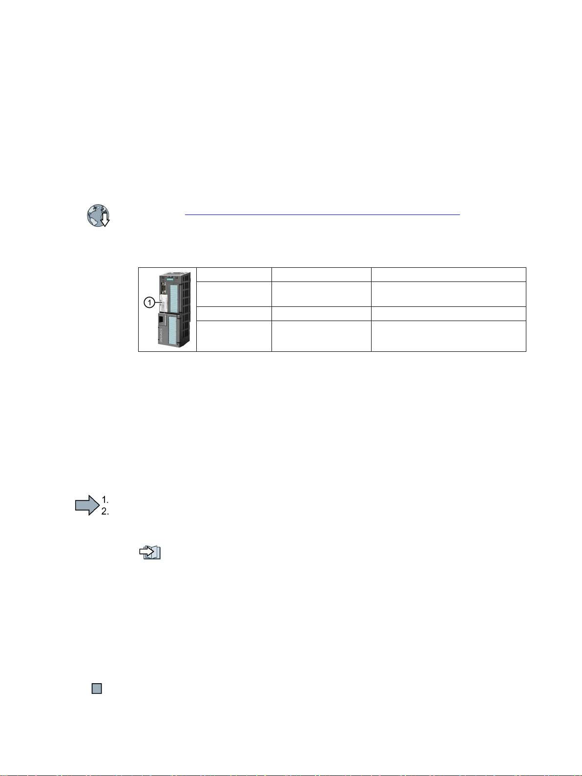
The fieldbus interface of the Control Unit depends on the Article No. You can find the
designation, the article number, the hardware version (e.g. 02) and the firmware version
(e.g. 4.6) on the Control Unit rating plate
CU230P-2 HVAC 6SL3243-0BB30-1HA3 USS, Modbus RTU, BACnet MS/TP,
①.
CU230P-2 PN 6SL3243-0BB30-1FA0 PROFINET IO, EtherNet/IP
● Compact Operating Instructions in German and English
● The inverter contains open-source software (OSS). OSS comprises open source text and
satisfies special license terms.
The OSS license terms are saved in the inverter. You can transfer the OSS license terms
to a PC using a memory card where you can read them.
To transfer OSS license terms to a PC, proceed as follows:
1. Switch off the inverter power supply.
2. Insert an empty memory card into the card slot of the inverter.
Overview of the interfaces (Page 10)
3. Switch on the inverter power supply.
4. The inverter writes file "Read_OSS.ZIP" to the memory card within approximately
30 seconds.
CU230P-2 Control Units
6 Compact Operating Instructions, 01/2017, A5E38815802B AA
5. Switch off the inverter power supply.
6. Withdraw the memory card from the inverter.
7. Insert the memory card into the card reader of a PC.
8. Please read the license terms.
You have transferred the OSS license terms to a PC.
Page 7
3
3.1
Plugging the Control Unit onto the Power Module
Permissible Power Modules
You may operate the Control Unit with the following Power Modules:
•
•
•
•
•
Installing the Control Unit - General
Inserting the Control Unit
1.
2.
Power Module until you hear that it
Removing the Control Unit
Special features for the PM330 Power Module
To insert or detach the Control Unit, you must open the left
hand cov
Close the cover before you commission the inverter.
PM230
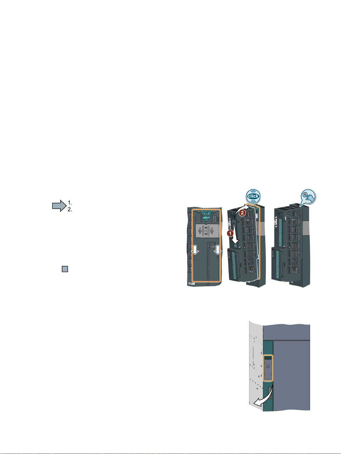
Each Power Module has an appropriate holder for the Control Unit and a release
mechanism.
Proceed as follows to plug the Control
Unit onto a Power Module:
Place the two catches of the
Control Unit in the matching
grooves of the Power Module.
Press the Control Unit onto the
latches.
You have now plugged the Control
Unit onto the Power Module.
PM240P-2
PM240-2
PM250
PM330
Remove the Control Unit from the Power Module by pressing the release mechanism.
CU230P-2 Control Units
Compact Operating Instructions, 01/2017, A5E38815802B AA
er of the Power Module.
-
7
Page 8
Installing
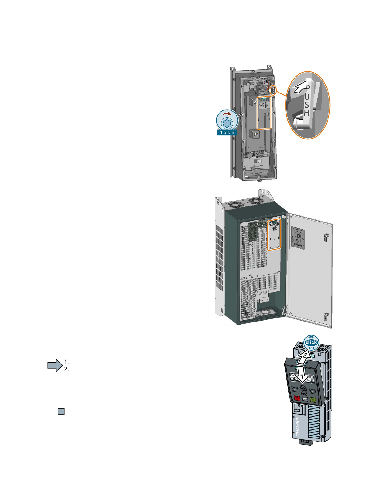
Special features for the PM230 Power Module IP55, FSA … FSC
To insert or detach the
release eight or ten fixing screws of the cover
and then remove the cover.
The Power Module release mechanism is
shown in the diagram.
Attach the cover again before you commission
the inverter. Do not damage the seal of the
cover when attaching it.
Installing the Control Unit, PM230 IP55 - FSD … FSF
To insert or detach the Control Unit, you must
open the front door of the Power Module.
Clos
verter. Check to ensure that the seals are not
damaged.
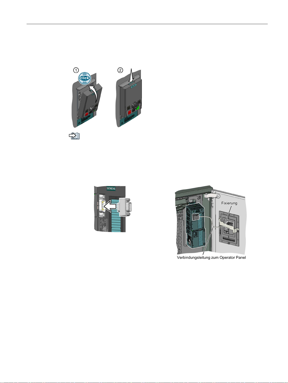
Plugging on an operator panel
Procedure
1.
2.
3.1 Plugging the Control Unit onto the Power Module
Control Unit, you must
e the door before you commission the in-
To plug an Operator Panel on the Control Unit, proceed as follows:
Locate the lower edge of the Operator Panel into the matching recess
of the Control Unit.
Plug the Operator Panel onto the inverter until the latch audibly
engages.
You have plugged an operator panel onto the Control Unit.
The operator panel is ready for operation when you connect the inverter to the power supply.
CU230P-2 Control Units
8 Compact Operating Instructions, 01/2017, A5E38815802B AA
Page 9
Installing
Mounting the operator panel or dummy cover on the IP55 Power Module
①
Attaching the operator panel or dummy cover:
Press the operator panel or dummy cover onto the
inverter as shown until you hear it click into place.
②
Removing the operator panel or dummy cover:
Use a suitable screwdriver to pres
downwards.
Connecting cable
3.1 Plugging the Control Unit onto the Power Module
Either an operator panel or the dummy cover must be plugged on for the inverter to achieve
degree of protection IP55.
s the interlock
Tools to commission the converter (Page 33)
The following accessory is included in the Power Module scope of supply to connect the
Control Unit with the operator panel:
● An adapter, required for PM230 IP55 Power Modules, FSA … FSC
● A connecting cable and a bar to fix the connector, required for PM230 IP55 Power
Modules, FSD … FSF
Adapter
CU230P-2 Control Units
Compact Operating Instructions, 01/2017, A5E38815802B AA
9
Page 10
Installing
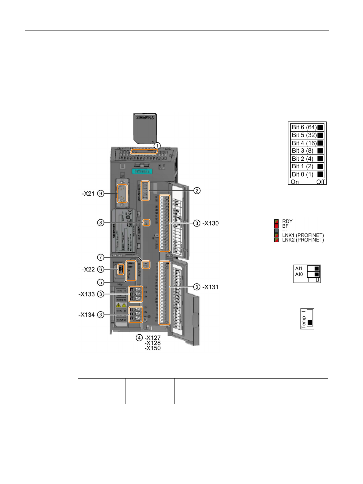
3.2
Overview of the interfaces
Interfaces at the front of the Control Unit
①
Memory card slot
②
Selecting the
fieldbus address:
•
•
•
③
Terminal strips
④
Fieldbus interfaces at the lower
side
⑤
Status LED
⑥
USB interface for connection to a
PC
⑦
Switch for AI
AI
•
•
⑧
Switch for AI
Current or te
per
⑨
Connection to the operator panel
Digital inputs DI
Digital outputs DO
Analog inputs AI
Analog outputs AO
Input for motor tem-
perature sensor
6 3 4 2 1
3.2 Overview of the interfaces
To access the interfaces at the front of the Control Unit, you must lift the Operator Panel (if
one is being used) and open the front doors.
CU230P-2 DP
CU230P-2
HVAC
CU230P-2 BT
Table 3- 1 Number of inputs and outputs
1 (U/I)
I 0/4 mA … 20 mA
U -10/0 V … 10 V
ature input
0 and
2
m-
CU230P-2 Control Units
10 Compact Operating Instructions, 01/2017, A5E38815802B AA
Page 11
Installing
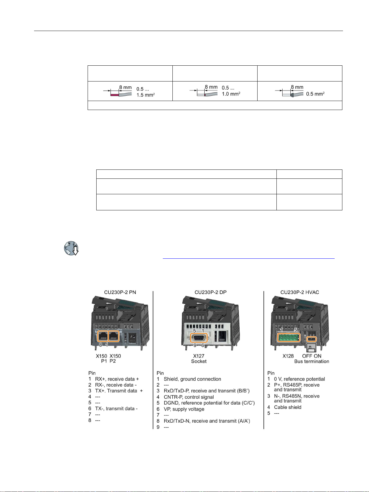
Cables with twin end sleeves are not permissible.
EMC-compliant wiring
Shield connection kit
Article number
interfaces except for PROFINET.
Interfaces at the lower side of the CU230P-2 Control Unit
3.2 Overview of the interfaces
Table 3- 2 Permissible cables and wiring options
Solid or flexible conductors Finely stranded conductor with
Measures to ensure EMC-compliant wiring of the Control Unit:
● Use the shield connection kit of the Control Unit to connect the shield and provide strain
relief for cables/conductors.
● If you use shielded cables, then you must connect the shield to the mounting plate of the
control cabinet or with the shield support of the inverter through a good electrical
connection and a large surface area.
Additional information about EMC-compliant wiring is available on the Internet:
Finely stranded conductor with
non-insulated end sleeve
Shield connection kit 1 for the CU230P-2 Control Units with all fieldbus
Shield connection kit 3 for the CU230P-2 and CU240E-2 Control Units
with PROFINET interface.
partially insulated end sleeve
6SL3264-1EA00-0FA0
6SL3264-1EA00-0HB0
EMC installation guideline (http://support.automation.siemens.com/WW/view/en/60612658)
CU230P-2 Control Units
Compact Operating Instructions, 01/2017, A5E38815802B AA
11
Page 12
Installing
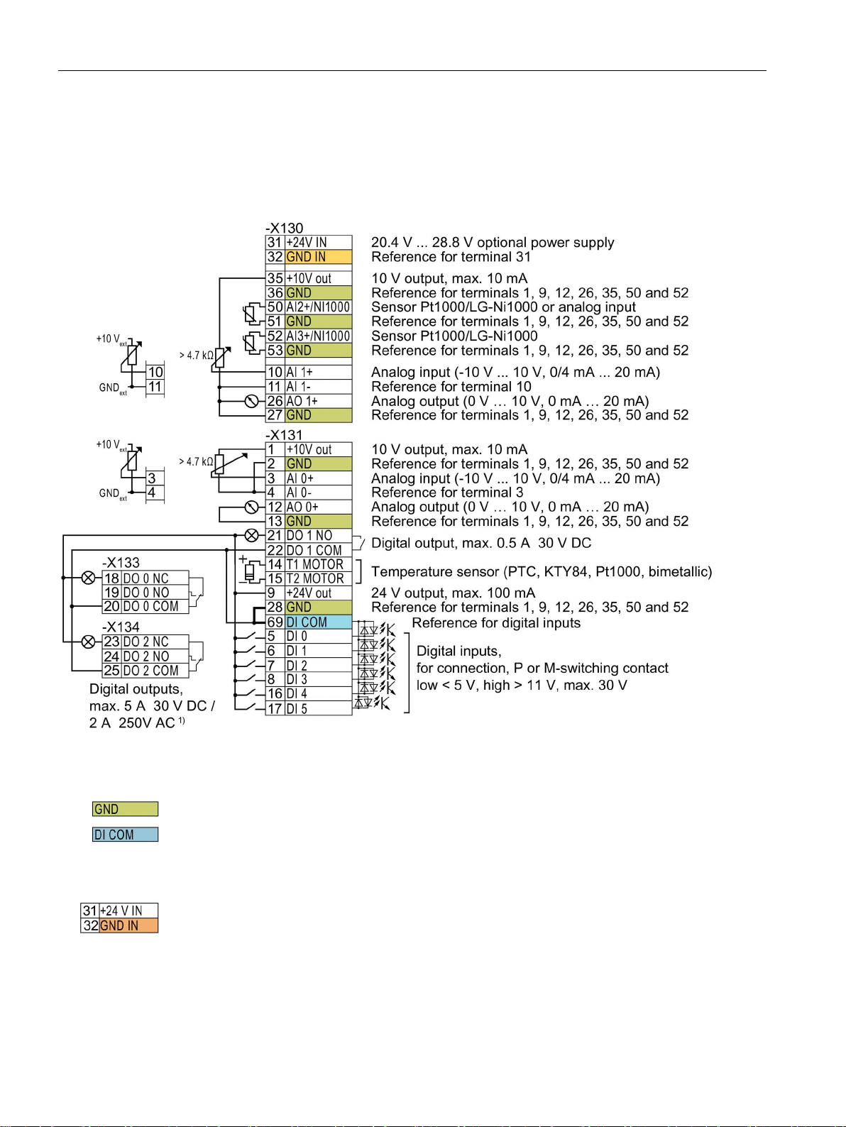
3.3
Terminal strips
Terminal strips with wiring example
The following applies to systems compliant with UL: Maximum current, 3 A 30 VDC or 2 A 250 VAC
3.3 Terminal strips
1)
Figure 3-1 Wiring the digital inputs with p-switching contacts and an internal 24 V power supply (terminal 9)
All terminals labelled with reference potential "GND" are connected internally in the inverter.
Reference potential "DI COM" is electrically isolated from "GND". The Control Unit is
delivered with a jumper between terminals 28 and 69.
→ If, as shown above, you wish to use the 24-V supply from terminal 9 as supply for the
digital inputs, then it is mandatory that this jumper is used.
When an optional 24 V power supply is connected at terminals 31, 32, even when the Power
Module is disconnected from the line supply, the Control Unit remains in operation. The
Control Unit thus maintains fieldbus communication, for example.
→ At terminals 31, 32, only connect a power supply that is in accordance with SELV (Safety
Extra Low Voltage) or PELV (Protective Extra Low Voltage).
CU230P-2 Control Units
12 Compact Operating Instructions, 01/2017, A5E38815802B AA
Page 13
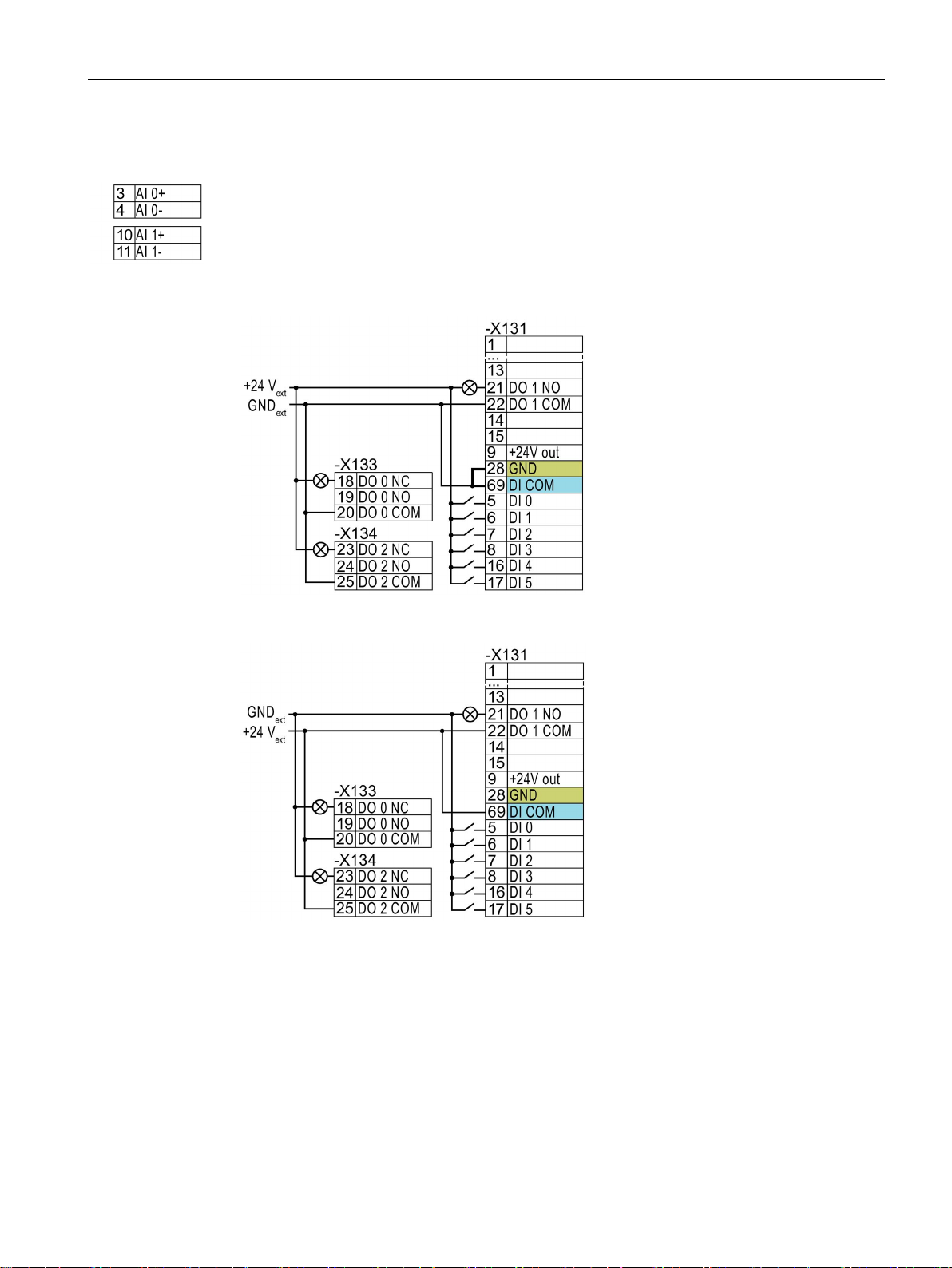
→ if you also wish to use the power supply at terminals 31, 32 for the digital inputs, then you
Additional options for wiring the digital inputs
power supply
You must remove the jumper between
terminals 28 and 69 if it is necessary to
have electrical isolation between the
external power supply and the internal
inverter power supply.
power supply
Remove the jumper between terminals
28 and 69.
must connect "DI COM" and "GND IN" with one another at the terminals.
You may use the internal 10 V power supply or an external power supply for the analog
inputs.
→ When you use the internal 10 V power supply, you must connect AI 0 or AI 1 with "GND".
Installing
3.3 Terminal strips
Connecting P-switching contacts with an external
Connecting M-switching contacts with an external
CU230P-2 Control Units
Compact Operating Instructions, 01/2017, A5E38815802B AA
13
Page 14
Installing
3.4
Factory interface settings
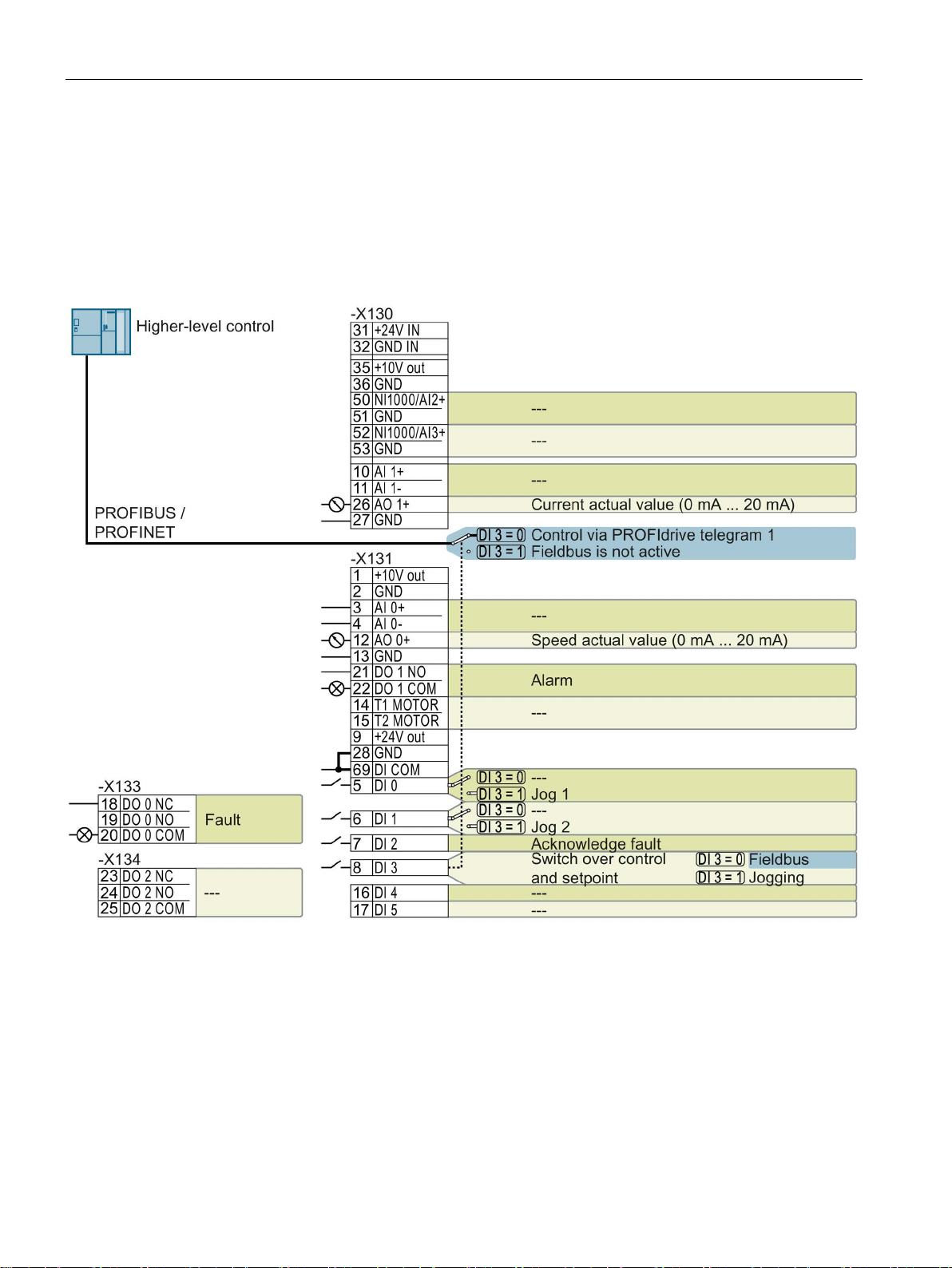
Control Units with PROFIBUS or PROFINET interface
--- No function.
DO x: p073x
AO 0: p0771[0]
DI x: r0722.x
Speed setpoint (main setpoint): p1070[0] = 2050[1]
3.4 Factory interface settings
The factory setting of the interfaces depends on the Control Unit.
The function of the fieldbus interface and digital inputs DI 0, DI 1 depends on DI 3.
Figure 3-2 Factory setting of the CU230P-2 DP and CU230P-2 PN Control Units
CU230P-2 Control Units
14 Compact Operating Instructions, 01/2017, A5E38815802B AA
Page 15
Installing
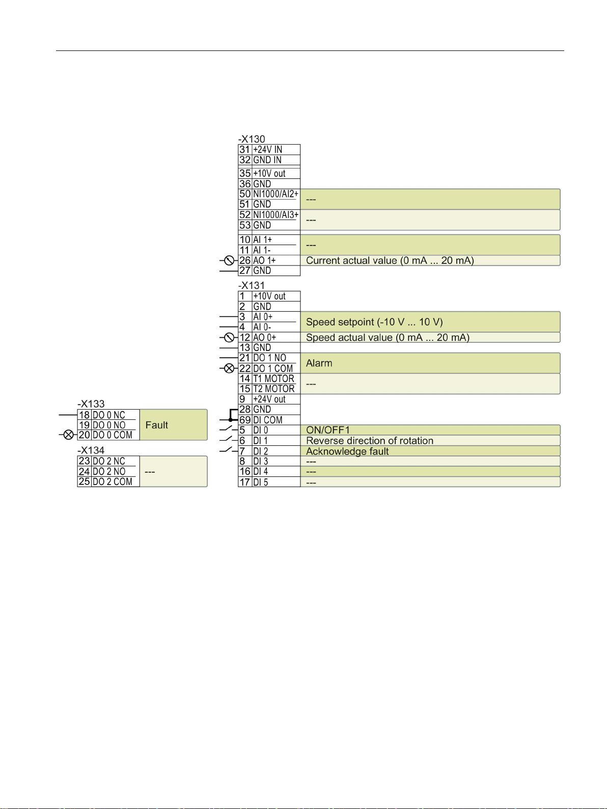
Control Units with USS interface
--- No function.
DO x: p073x
AO 0: p0771[0]
DI x: r0722.x
AI 0: r0755[0]
Speed setpoint (main setpoint): p1070[0] = 755[0]
Changing the function of the terminals
3.4 Factory interface settings
The fieldbus interface is not active.
Figure 3-3 Factory setting of CU230P-2 HVAC Control Units
The function of the terminals and fieldbus interface can be adjusted.
In order that you do not have to successively change terminal for terminal, several terminals
can be jointly set using default settings ("p0015 Macro drive unit").
The terminal settings made in the factory described above correspond to the following
default settings:
● Default setting 12 (p0015 = 12): "Standard I/O with analog setpoint"
● Default setting 7 (p0015 = 7): "Fieldbus with data set switchover"
CU230P-2 Control Units
Compact Operating Instructions, 01/2017, A5E38815802B AA
15
Page 16
Installing
3.5
Default setting of the interfaces
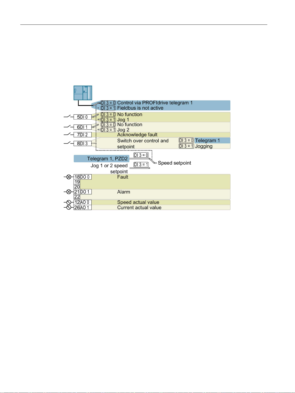
Default setting 7: "Fieldbus with data set switchover"
DO 0: p0730, DO 1: p0731
AO 0: p0771[0], AO 1: p0771[1]
DI 0: r0722.0, …, DI 3: r0722.3
Jog 2 speed setpoint: p1059, factory setting: -150 rpm
Designation in the BOP-2: FB cdS
3.5 Default setting of the interfaces
Factory setting for inverters with PROFIBUS or PROFINET interface
Speed setpoint (main setpoint): p1070[0] = 2050[1]
Jog 1 speed setpoint: p1058, factory setting: 150 rpm
CU230P-2 Control Units
16 Compact Operating Instructions, 01/2017, A5E38815802B AA
Page 17

Installing
Default setting 9: "Standard I/O with MOP"
DO 0: p0730, DO 1: p0731
AO 0: p0771[0], AO 1: p0771[1]
DI 0: r0722.0, …, DI 3: r0722.3
Speed setpoint (main setpoint): p1070[0] = 1050
Designation in the BOP-2: Std MoP
Default setting 12: "Standard I/O with analog setpoint"
DO 1: p0731
AO 1: p0771[1]
Speed setpoint (main setpoint): p1070[0] = 755[0]
Designation in the BOP-2: Std ASP
3.5 Default setting of the interfaces
Motorized potentiometer, setpoint after the ramp-function generator: r1050
Factory setting for inverters with USS, Modbus, BACnet, MS/TP or P1 interface
DO 0: p0730,
AO 0: p0771[0],
DI 0: r0722.0, …, DI 2: r0722.2 AI 0: r0755[0]
CU230P-2 Control Units
Compact Operating Instructions, 01/2017, A5E38815802B AA
17
Page 18

Installing
Default setting 14: "Process industry with fieldbus"
DO 0: p0730, DO 1: p0731
AO 0: p0771[0], AO 1: p0771[1]
DI 0: r0722.0, …, DI 5: r0722.5
Speed setpoint (main setpoint): p1070[0] = 2050[1], p1070[1] = 1050
Designation in the BOP-2: Proc Fb
3.5 Default setting of the interfaces
Motorized potentiometer, setpoint after the ramp-function generator: r1050
CU230P-2 Control Units
18 Compact Operating Instructions, 01/2017, A5E38815802B AA
Page 19

Installing
Default setting 15: "Process industry"
DO 1: p0731
AO 1: p0771[1]
Speed setpoint (main setpoint): p1070[0] = 755[0], p1070[1] = 1050
Designation in the BOP-2: Proc
Default setting 17: "2-wire (forward/backward 1)"
DO 1: p0731
AO 1: p0771[1]
Speed setpoint (main setpoint): p1070[0] = 755[0]
Designation in the BOP-2: 2-wIrE 1
3.5 Default setting of the interfaces
DO 0: p0730,
Motorized potentiometer, setpoint after the ramp-function generator: r1050
AO 0: p0771[0],
DO 0: p0730,
AO 0: p0771[0],
DI 0: r0722.0, …, DI 5: r0722.5 AI 0: r0755[0]
DI 0: r0722.0, …, DI 2: r0722.2 AI 0: r0755[0]
CU230P-2 Control Units
Compact Operating Instructions, 01/2017, A5E38815802B AA
19
Page 20

Installing
Default setting 18: "2-wire (forward/backward 2)"
DO 1: p0731
AO 1: p0771[1]
Speed setpoint (main setpoint): p1070[0] = 755[0]
Designation in the BOP-2: 2-wIrE 2
Default setting 19: "3-wire (enable/forward/backward)"
DO 1: p0731
AO 1: p0771[1]
Speed setpoint (main setpoint): p1070[0] = 755[0]
Designation in the BOP-2: 3-wIrE 1
3.5 Default setting of the interfaces
DO 0: p0730,
AO 0: p0771[0],
DI 0: r0722.0, …, DI 2: r0722.2 AI 0: r0755[0]
DO 0: p0730,
CU230P-2 Control Units
AO 0: p0771[0],
DI 0: r0722.0, …, DI 4: r0722.4 AI 0: r0755[0]
20 Compact Operating Instructions, 01/2017, A5E38815802B AA
Page 21

Installing
Default setting 20: "3-wire (enable/on/reverse)"
DO 1: p0731
AO 1: p0771[1]
Speed setpoint (main setpoint): p1070[0] = 755[0]
Designation in the BOP-2: 3-wIrE 2
Default setting 21: "USS fieldbus"
DO 0: p0730, DO 1: p0731
AO 0: p0771[0], AO 1: p0771[1]
DI 2: r0722.2
Speed setpoint (main setpoint): p1070[0] = 2050[1]
Designation in the BOP-2: FB USS
3.5 Default setting of the interfaces
DO 0: p0730,
AO 0: p0771[0],
DI 0: r0722.0, …, DI 4: r0722.4 AI 0: r0755[0]
CU230P-2 Control Units
Compact Operating Instructions, 01/2017, A5E38815802B AA
21
Page 22

Installing
Default setting 101: "Universal application"
DO 2: p0732
Designation in the BOP-2: P_F 6PA
3.5 Default setting of the interfaces
DO 0: p0730, …,
Additional settings:
• Fixed speed setpoint 1: p1001 = 800 rpm
• Fixed speed setpoint 2: p1002 = 1000 rpm
• Fixed speed setpoint 3: p1003 = 1200 rpm
• If several of the DI 3 ... DI 5 = high, the inverter adds the corresponding fixed speeds.
• Fixed speed setpoint 15 for essential service mode (ESM): p1015 = 1500 rpm
• "Flying restart" is enabled: p1200 = 1
• Automatic restart is active. After a power failure, the inverter automatically acknowledges possible
faults and switches on the motor: p1210 = 26
AO 0: p0771[0], AO 1: p0771[1] DI 0: r0722.0, …, DI 5: r0722.5 AI 0: r0755[0]
CU230P-2 Control Units
22 Compact Operating Instructions, 01/2017, A5E38815802B AA
Page 23

Installing
Default setting 103: "Pump pressure control"
DO 0: p0730, …, DO 2: p0732
AO 0: p0771[0], AO 1: p0771[1]
DI 0: r0722.0
AI 0: r0755[0]
Designation in the BOP-2: P_F dPc
3.5 Default setting of the interfaces
Additional settings:
• Differential pressure control using the technology controller
• Technological unit: p0595 = 1 (%), reference variable: p0596 = 1
• Default setting of the technology controller:
– Enable: p2200 = 1
– Fixed value 1: p2201 = 50 %
– Ramp-up/down time for setpoint: p2257 = p2258 = 30 s
– Ramp-up/down time for controller output: p2293 = 30 s
– Upper and lower limits, actual value: p2267 = 120 %, p2268 = -10 %
– Actual value filter time constant: p2265 = 10 s
– Proportional gain K
p2285 (T
) = 30 s, p2274 (TD) = 0 s
I
• "Flying restart" is enabled: p1200 = 1
• Automatic restart is active. After a power failure, the inverter automatically acknowledges possible
faults and switches on the motor: p1210 = 26
, integral time TI, differentiation time constant TD: p2280 (KP) = 1,
P
CU230P-2 Control Units
Compact Operating Instructions, 01/2017, A5E38815802B AA
23
Page 24

Installing
Default setting 104: "ESM stairwell pressure control"
DO 0: p0730, …, DO 2: p0732
AO 0: p0771[0], AO 1: p0771[1]
DI 0: r0722.0
AI 0: r0755[0]
Designation in the BOP-2: P_F Stw
3.5 Default setting of the interfaces
Additional settings:
• Pressure control using the technology controller
• Analog inputs smoothing time constant: p0753 = 500 ms
• Technological unit: p0595 = 1 (%), reference variable: p0596 = 1
• Default setting of the technology controller:
– Enable: p2200 = 1
– Fixed value 1: p2201 = 40 %
– Ramp-up/down time for setpoint: p2257 = p2258 = 30 s
– Ramp-up/down time for controller output: p2293 = 30 s
– Upper and lower limits, actual value: p2267 = 120 %, p2268 = -10 %
– Actual value filter time constant: p2265 = 10 s
– Proportional gain K
p2285 (T
) = 25 s, p2274 (TD) = 0 s
I
– Technology controller minimum limiting p2292 = 30 %
– Technology controller output signal start value p2302 = 35 %
• "Flying restart" is enabled: p1200 = 1
• Automatic restart is active. After a power failure, the inverter automatically acknowledges possible
faults and switches on the motor: p1210 = 26
, integral time TI, differentiation time constant TD: p2280 (KP) = 1.2,
P
CU230P-2 Control Units
24 Compact Operating Instructions, 01/2017, A5E38815802B AA
Page 25

Installing
Default setting 105: "Fan pressure control + ESM with fixed setpoint"
DO 2: p0732
Designation in the BOP-2: P_F Pc5
3.5 Default setting of the interfaces
DO 0: p0730, …,
AO 0: p0771[0], AO 1: p0771[1] DI 0: r0722.0, DI 1: r0722.1 AI 0: r0755[0]
Additional settings:
• Pressure control using the technology controller
• Analog inputs smoothing time constant: p0753 = 500 ms
• Technological unit: p0595 = 1 (%), reference variable: p0596 = 1
• Fixed speed setpoint 15 for essential service mode (ESM): p1015 = 1350 rpm
• Default setting of the technology controller:
– Enable: p2200 = 1
– Fixed value 1: p2201 = 40 %
– Ramp-up/down time for setpoint: p2257 = p2258 = 30 s
– Ramp-up/down time for controller output: p2293 = 30 s
– Upper and lower limits, actual value: p2267 = 120 %, p2268 = -10 %
– Actual value filter time constant: p2265 = 10 s
– Proportional gain K
p2285 (T
) = 35 s, p2274 (TD) = 0 s
I
, integral time TI, differentiation time constant TD: p2280 (KP) = 1.1,
P
– Technology controller minimum limiting p2292 = 20 %
– Technology controller output signal start value p2302 = 50 %
• "Flying restart" is enabled: p1200 = 1
• Automatic restart is active. After a power failure, the inverter automatically acknowledges possible
faults and switches on the motor: p1210 = 26
CU230P-2 Control Units
Compact Operating Instructions, 01/2017, A5E38815802B AA
25
Page 26

Installing
Default setting 106: "Cooling tower with active sensor + hibernation"
DO 0: p0730, …, DO 2: p0732
AO 0: p0771[0], AO 1: p0771[1]
DI 0: r0722.0
AI 0: r0755[0]
Designation in the BOP-2: P_F ctF1
3.5 Default setting of the interfaces
Additional settings:
• Temperature control using the technology controller
• Analog inputs smoothing time constant: p0753 = 100 ms
• Technological unit: p0595 = 1 (%), reference variable: p0596 = 1
• Default setting of the technology controller:
– Enable: p2200 = 1
– Fixed value 1: p2201 = 26 %
– Ramp-up/down time for setpoint: p2257 = p2258 = 30 s
– Ramp-up/down time for controller output: p2293 = 30 s
– Upper and lower limits, actual value: p2267 = 120 %, p2268 = -10 %
– Actual value filter time constant: p2265 = 10 s
– Proportional gain K
p2285 (T
) = 25 s, p2274 (TD) = 0 s
I
– Technology controller system deviation inversion: p2306 = 1
• Default setting hibernation mode:
– Activated: p2398 = 1
– Start speed: p2390 = 50 rpm
– Delay time: p2391 = 60 s
– Restart value with technology controller: p2392 = 1 %
– Restart speed relative w/o technology controller: p2393 = 100 rpm
• "Flying restart" is enabled: p1200 = 1
• Automatic restart is active. After a power failure, the inverter automatically acknowledges possible
faults and switches on the motor: p1210 = 26
, integral time TI, differentiation time constant TD: p2280 (KP) = 1.2,
P
CU230P-2 Control Units
26 Compact Operating Instructions, 01/2017, A5E38815802B AA
Page 27

Installing
Default setting 107: "Cooling tower with LG-Ni1000 sensor + hibernation"
DO 0: p0730, …, DO 2: p0732
AO 0: p0771[0], AO 1: p0771[1]
DI 0: r0722.0
AI 3: r0755[3]
Designation in the BOP-2: P_F ctF2
3.5 Default setting of the interfaces
Additional settings:
• Temperature control using the technology controller
• Analog inputs smoothing time constant: p0753 = 100 ms
• Technological unit: p0595 = 1 (%), reference variable: p0596 = 1
• Default setting of the technology controller:
– Enable: p2200 = 1
– Fixed value 1: p2201 = 26 %
– Ramp-up/down time for setpoint: p2257 = p2258 = 30 s
– Ramp-up/down time for controller output: p2293 = 30 s
– Upper and lower limits, actual value: p2267 = 120 %, p2268 = -100 %
– Actual value filter time constant: p2265 = 10 s
– Proportional gain K
p2285 (T
) = 25 s, p2274 (TD) = 0 s
I
– Technology controller minimum limiting p2292 = 20 %
– Technology controller system deviation inversion: p2306 = 1
• Default setting hibernation mode:
– Activated: p2398 = 1
– Start speed: p2390 = 50 rpm
– Delay time: p2391 = 60 s
– Restart value with technology controller: p2392 = 1 %
– Restart speed relative w/o technology controller: p2393 = 100 rpm
• "Flying restart" is enabled: p1200 = 1
• Automatic restart is active. After a power failure, the inverter automatically acknowledges possible
faults and switches on the motor: p1210 = 26
, integral time TI, differentiation time constant TD: p2280 (KP) = 1.2,
P
CU230P-2 Control Units
Compact Operating Instructions, 01/2017, A5E38815802B AA
27
Page 28

Installing
Default setting 108: "USS fieldbus"
DO 0: p0730, …, DO 2: p0732
AO 0: p0771[0], AO 1: p0771[1]
DI 2: r0722.2
Designation in the BOP-2: P_F USS
Default setting 109: "Modbus RTU field"
DO 0: p0730, …, DO 2: p0732
AO 0: p0771[0], AO 1: p0771[1]
DI 2: r0722.2
Designation in the BOP-2: P_F Mod
3.5 Default setting of the interfaces
CU230P-2 Control Units
28 Compact Operating Instructions, 01/2017, A5E38815802B AA
Page 29

Installing
Default setting 110: "BACnet MS/TP fieldbus"
DO 0: p0730, …, DO 2: p0732
AO 0: p0771[0], AO 1: p0771[1]
DI 2: r0722.2
Designation in the BOP-2: P_F bAc
Default setting 111: "Fixed setpoints"
DO 0: p0730, …, DO 2: p0732
AO 0: p0771[0], AO 1: p0771[1]
DI 0: r0722.0, …, DI 3: r0722.3
Designation in the BOP-2: P_F _F55
3.5 Default setting of the interfaces
Additional settings:
• Fixed speed setpoint 1: p1001 = 300 rpm
• Fixed speed setpoint 2: p1002 = 600 rpm
• Fixed speed setpoint 3: p1003 = 900 rpm
• Fixed speed setpoint 4: p1004 = 1200 rpm
• If several of the DI 0 ... DI 3 = high, the inverter adds the corresponding fixed speeds.
• "Flying restart" is enabled: p1200 = 1
• Automatic restart is active. After a power failure, the inverter automatically acknowledges possible
faults and switches on the motor: p1210 = 26
CU230P-2 Control Units
Compact Operating Instructions, 01/2017, A5E38815802B AA
29
Page 30

Installing
Default setting 112: "CO2 sensor, 2 PID setpoints"
DO 2: p0732
Designation in the BOP-2: P_F_CO2
3.5 Default setting of the interfaces
DO 0: p0730, …,
AO 0: p0771[0], AO 1: p0771[1] DI 0: r0722.0, DI 2: r0722.2 AI 0: r0755[0]
Additional settings:
• CO
• Analog inputs smoothing time constant: p0753 = 500 ms
• Technological unit: p0595 = 1 (%), reference variable: p0596 = 1
• Default setting of the technology controller:
• "Flying restart" is enabled: p1200 = 1
• Automatic restart is active. After a power failure, the inverter automatically acknowledges possible
control using the technology controller
2
– Enable: p2200 = 1
– Fixed value 1: p2201 = 50 %
– Fixed value 3: p2203 = 10 %
– Technology controller setpoint 1: p2253 = r2224 (active fixed value)
– Ramp-up/down time for setpoint: p2257 = p2258 = 30 s
– Upper and lower limits, actual value: p2267 = 120 %, p2268 = -10 %
– Actual value filter time constant: p2265 = 10 s
– Technology controller system deviation inversion: p2306 = 1
faults and switches on the motor: p1210 = 26
CU230P-2 Control Units
30 Compact Operating Instructions, 01/2017, A5E38815802B AA
Page 31

Installing
Default setting 113: "Temperature-dependent pressure setpoint"
DO 2: p0732
Designation in the BOP-2: P_F_tP5
3.5 Default setting of the interfaces
DO 0: p0730, …,
AO 0: p0771[0], AO 1: p0771[1] DI 0: r0722.0 AI 0: r0755[0], AI 2: r0755[2]
Additional settings:
• Temperature control using the technology controller
• Technological unit: p0595 = 1 (%), reference variable: p0596 = 1
• Default setting of the technology controller:
– Enable: p2200 = 1
– Upper and lower limits, setpoint: p20229 = 0.5 , p20230 = 0.2
– Ramp-up/down time for setpoint: p2257 = p2258 = 30 s
– Ramp-up/down time for controller output: p2293 = 30 s
– Upper and lower limits, actual value: p2267 = 120 %, p2268 = -10 %
– Actual value filter time constant: p2265 = 10 s
– Technology controller minimum limiting p2292 = 20 %
• "Flying restart" is enabled: p1200 = 1
• Automatic restart is active. After a power failure, the inverter automatically acknowledges possible
faults and switches on the motor: p1210 = 26
CU230P-2 Control Units
Compact Operating Instructions, 01/2017, A5E38815802B AA
31
Page 32

Installing
Default setting 114: "P1 fieldbus"
DO 0: p0730, …, DO 2: p0732
AO 0: p0771[0], AO 1: p0771[1]
DI 2: r0722.2
Designation in the BOP-2: p_f_P1
Default setting 120: "PID settings for pumps and fans"
3.5 Default setting of the interfaces
The default setting restores the function of the terminal strip to the factory setting.
Technology controller setting:
● Ramp-up/down time for setpoint: p2257 = p2258 = 30 s
● Ramp-up/down time for controller output: p2293 = 30 s
● Actual value upper limit: p2267 = 120%
● Actual value filter time constant: p2265 = 10 s
Designation in the BOP-2: P_F_PID
CU230P-2 Control Units
32 Compact Operating Instructions, 01/2017, A5E38815802B AA
Page 33

4
4.1
Tools to commission the converter
Operator panel
Intelligent Operator Panel (IOP)
Operator Panel BOP-2
PC tools
STARTER
Startdrive
An operator panel is used to commission, troubleshoot and control the inverter, as well as to
back up and transfer the inverter settings.
The
handheld with a connecting cable to the inverter. The graphics-capable plain text display of
the IOP enables intuitive operation and diagnostics of the inverter.
The IOP is available in two versions:
● With European languages
● With Chinese, English and German
is available for snapping onto the inverter, or as
Additional information about the compatibility of the IOP and inverters is available in the
Internet:
Compatibility of the IOP and Control Units
(http://support.automation.siemens.com/WW/view/en/67273266)
The
diagnostics and operating the inverter.
Operating Instructions of the BOP-2 and IOP operator panels:
Overview of the manuals (Page 49)
the inverter, as well as to back up and transfer the inverter settings. You can connect the PC
with the inverter via USB or via the PROFIBUS / PROFINET fieldbus.
Connecting cable (3 m) between PC and inverter: Article number 6SL3255-0AA00-2CA0
STARTER DVD: Article number 6SL3072-0AA00-0AG0
Startdrive DVD: Article number 6SL3072-4CA02-1XG0
STARTER (http://support.automation.siemens.com/WW/view/en/26233208)
and
for snapping onto the inverter has a two-line display for
are PC tools that are used to commission, troubleshoot and control
Startdrive (http://support.automation.siemens.com/WW/view/en/68034568)
STARTER videos (http://www.automation.siemens.com/mcms/mc-drives/en/low-voltage-
inverter/sinamics-g120/videos/Pages/videos.aspx)
Startdrive tutorial (http://support.automation.siemens.com/WW/view/en/73598459)
CU230P-2 Control Units
Compact Operating Instructions, 01/2017, A5E38815802B AA
33
Page 34

Commissioning
4.2
Commissioning with BOP-2 operator panel
4.2.1
Start quick commissioning and select the application class
Starting quick commissioning
Preconditions
Procedure
4.2 Commissioning with BOP-2 operator panel
● The power supply is switched on.
● The operator panel displays setpoints and actual values.
Proceed as follows to carry out quick commissioning:
Press the ESC key.
Press one of the arrow keys until the BOP-2 displays the "SETUP" menu.
To start quick commissioning, in the "SETUP" menu, press the OK key.
If you wish to restore all of the parameters to the factory setting before the quick
commissioning, proceed as follows:
1. Press the OK key.
2. Switchover the display using an arrow key: nO → YES
3. Press the OK key.
You must select the application class if you are not using a PM230, but instead, a PM240-2,
PM240P-2 or PM330 Power Module. The next steps after having selected an application
class are described in the operating instructions.
Overview of the manuals (Page 49)
Select the motor standard.
● KW 50HZ: IEC
● HP 60HZ: NEMA
● KW 60HZ: IEC 60 Hz
Set the inverter supply voltage.
Select the motor type. If a 5-digit motor code is stamped on the motor rating plate, select the
corresponding motor type with motor code.
Motors without motor code stamped on the rating plate:
● INDUCT: Third-party induction motor
● 1L… IND: 1LE1, 1LG6, 1LA7, 1LA9 induction motors
CU230P-2 Control Units
34 Compact Operating Instructions, 01/2017, A5E38815802B AA
Page 35

Commissioning
4.2 Commissioning with BOP-2 operator panel
Motors with motor code stamped on the rating plate:
● 1LE1 IND 100: 1LE1 . 9
● 1PC1 IND: 1PC1
● 1PH8 IND: Induction motor
● 1FP1: Reluctance motor
Depending on the inverter, the motor list in BOP-2 can deviate from the list shown above.
If you have selected a motor type with motor code, you must now enter the motor code. The
inverter assigns the following motor data corresponding to the motor code.
If you do not know the motor code, then you must set the motor code = 0, and enter motor
data from p0304 and higher from the rating plate.
87 Hz motor operation The BOP-2 only indicates this step if you selected IEC as the motor
standard (EUR/USA, P100 = KW 50HZ).
Rated motor voltage
Rated motor current
Rated motor power
Rated motor frequency
Rated motor speed
Motor cooling:
● SELF: Natural cooling
● FORCED: Forced-air cooling
● LIQUID: Liquid cooling
● NO FAN: Without fan
Select the appropriate application:
● VEC STD: In all applications, which do not fit the other setting options.
● PUMP FAN: Applications involving pumps and fans
● SLVC 0HZ: Applications with short ramp-up and ramp-down times. However, this setting
is not suitable for hoisting gear and cranes/lifting gear.
● PUMP 0HZ: Setting only for steady-state operation with slow speed changes. We
recommend setting VEC STD if load surges in operation cannot be ruled out.
The selection option depends on the Power Module being used. There is no selection option
for PM230 Power Modules.
CU230P-2 Control Units
Compact Operating Instructions, 01/2017, A5E38815802B AA
35
Page 36

Commissioning
Select a suitable control mode
Control mode
U/f control with linear or square-law characteris-
tic
Flux current control (FCC)
Vector control without encoder
Closed-loop control characteristics
Typical correction time after a speed change:
Application examples
Motors that can be
operated
Power Modules
that can be operated
Max. output frequency
150 Hz with PM330 Power Module
Commissioning
4.2 Commissioning with BOP-2 operator panel
Select the control mode:
● VF LIN: U/f control with linear characteristic
● VF LIN F: Flux current control (FCC)
● VF QUAD: U/f control with square-law characteristic
● SPD N EN: Sensorless vector control
•
100 ms … 200 ms
• Typical correc-
tion time after a
load surge:
500 ms
• The control
mode is suitable
to address the
following requirements:
– Motor power
ratings < 45 kW
– Ramp-up time 0 → Rated speed (de-
pendent on the rated motor power):
1 s (0.1 kW) … 10 s (45 kW)
– Applications with increasing load torque
without load surges
• The control mode is insensitive with respect
to inaccurate motor data settings
• Typical correction time after a speed change:
< 100 ms
• Typical correction
time after a load
surge: 200 ms
• The vector control
controls and limits
the motor torque
• Torque accuracy
that can be
achieved: ± 5 % for
15 % … 100 % of
the rated speed
• We recommend vector control for the following
applications:
– Motor power ratings > 11 kW
– For load surges 10 % … >100 % of the rat-
ed motor torque
• The vector control is necessary for a ramp-up
time 0 → Rated speed (dependent on the rated
motor power):
< 1 s (0.1 kW) … < 10 s (250 kW).
CU230P-2 Control Units
36 Compact Operating Instructions, 01/2017, A5E38815802B AA
• Pumps, fans, and compressors with flow
characteristic
• Contrary to vector control, no speed control-
ler has to be set
• Pumps and compressors with displacement
machines
Induction motors Induction, synchronous and reluctance motors
No restrictions
550 Hz 240 Hz
Page 37

Commissioning
CAUTION
Material damage caused by the motor unexpectedly accelerating
4.2 Commissioning with BOP-2 operator panel
Select the default setting for the interfaces of the inverter that is suitable for your application.
Default setting of the interfaces (Page 16)
Figure 4-1 Minimum and maximum motor frequency
Depending on the particular Power Module, the inverter sets the minimum frequency p1080
to 20% of the maximum frequency. Also for a setpoint = 0, for p1080 > 0, after the motor is
switched on it accelerates to the minimum frequency. Material damage can occur if the
motor unexpectedly accelerates.
• If the application requires a minimum frequency = 0, then set p1080 = 0.
Scaling of analog input 0
Figure 4-2 Ramp-up and ramp-down time of the motor
Ramp-down time for the OFF3 command
Motor data identification: Select the method which the inverter uses to measure the data of
the connected motor:
● OFF: Motor data is not measured.
● STIL ROT: Recommended setting: Measure the motor data at standstill and with the
motor rotating. The inverter switches off the motor after the motor data identification has
been completed.
CU230P-2 Control Units
Compact Operating Instructions, 01/2017, A5E38815802B AA
37
Page 38

Commissioning
4.2.2
Identifying the motor data and optimizing the closed-loop control
WARNING
Risk of death due to machine motion while motor data identification is active
Preconditions
4.2 Commissioning with BOP-2 operator panel
● STILL: Measure the motor data at standstill. The inverter switches off the motor after the
motor data identification has been completed.
Select this setting if one of the following cases is applicable:
– You have selected the control mode "SPD N EN". However, the motor cannot rotate
freely – for example, if the traversing range is mechanically limited.
– You have selected U/f control as control mode, e.g. "VF LIN" or "VF QUAD".
● ROT: Measure the motor data with the motor rotating. The inverter switches off the motor
after the motor data identification has been completed.
Complete quick commissioning:
Switchover the display using an arrow key: nO → YES
Press the OK key.
You have completed quick commissioning.
The inverter has several techniques to automatically identify the motor data and optimize the
speed control.
To start the motor data identification routine, you must switch-on the motor via the terminal
strip, fieldbus or from the operator panel.
For the stationary measurement, the motor can make several rotations. The rotating
measurement accelerates the motor up to its rated speed. Secure dangerous machine
parts before starting motor data identification:
• Before switching on, ensure that nobody is working on the machine or located within its
working area.
• Secure the machine's work area against unintended access.
• Lower hanging/suspended loads to the floor.
● You selected a method of motor data identification during quick commissioning, e.g.
measuring motor data while the motor is stationary.
When quick commissioning is complete, the inverter issues alarm A07991.
● The motor has cooled down to the ambient temperature.
An excessively high motor temperature falsifies the motor data identification results.
CU230P-2 Control Units
38 Compact Operating Instructions, 01/2017, A5E38815802B AA
Page 39

Commissioning
Procedure when using the BOP-2 operator panel
4.2 Commissioning with BOP-2 operator panel
To start the motor data identification, proceed as follows:
Press the HAND/AUTO key.
The BOP-2 displays the symbol indicating manual operation.
Switch on the motor.
During motor data identification, "MOT-ID" flashes on the BOP-2.
If the inverter again outputs alarm A07991, then it waits for a new ON command to start the
rotating measurement.
If the inverter does not output alarm A07991, switch off the motor as described below, and
switch over the inverter control from HAND to AUTO.
Switch on the motor to start the rotating measurement.
During motor data identification, "MOT-ID" flashes on the BOP-2.
The motor data identification can take up to 2 minutes depending on the rated motor power.
Depending on the setting, after motor data identification has been completed, the inverter
switches off the motor - or it accelerates it to the setpoint.
If required, switch off the motor.
Switch the inverter control from HAND to AUTO.
You have completed the motor data identification.
CU230P-2 Control Units
Compact Operating Instructions, 01/2017, A5E38815802B AA
39
Page 40

Commissioning
4.3
Connecting the inverter to the fieldbus
Where can I find instructions for the fieldbus connection of the inverter?
Description files for fieldbuses
Alternative for the download for GSD and GSDML
4.3.1
PROFINET and PROFIBUS
Examples for telegrams via PROFIBUS and PROFINET
Telegram 1:
STW1
Control word 1
ZSW1
Status word 1
PZD01/02
Process data 16-bit
NSOLL_A
Speed setpoint
NIST_A
Speed actual value
4.3 Connecting the inverter to the fieldbus
Instructions for connecting to a fieldbus can be downloaded from the Internet:
● Application examples (http://support.automation.siemens.com/WW/view/en/60733299)
● Operating Instructions: CU230P-2 operating instructions
(https://support.industry.siemens.com/cs/ww/en/view/109478827)
● "Fieldbuses" function manual: Manuals for the Control Unit
(http://support.automation.siemens.com/WW/view/en/30563628/133300)
The description files are electronic device data sheets which contain all the required
information of a higher-level controller. You can configure and operate the inverter on a
fieldbus with the appropriate description file.
Generic Station Description for PROFIBUS: GSD
(http://support.automation.siemens.com/WW/view/en/23450835)
GSD Markup Language for PROFINET: GSDML
(http://support.automation.siemens.com/WW/view/en/26641490)
Ethernet/IP: EDS (http://support.automation.siemens.com/WW/view/en/78026217)
BACnet MS/TP: PICS (http://www.big-
eu.org/uploads/tx_teproddb/catalog_pdf/PICS_CU230P-2_HVAC_v46_HF.docx)
GSD and GSDML are saved in the inverter. If you insert a memory card in the inverter and
set p0804 = 12, then the inverter writes the GSD or the GSDML to the memory card. You
can then transfer the file to your programming device or PC using the memory card.
CU230P-2 Control Units
40 Compact Operating Instructions, 01/2017, A5E38815802B AA
Page 41

Commissioning
Te
STW1
Control word 1
IAIST_GLATT
Smoothed current actual
value
ZSW1
Status word 1
MIST_GLATT
Smoothed torque
PZD01/02
Process data 16-bit
PIST_GLATT
Smoothed active power
NSOLL_A
Speed setpoint
MELD_NAMUR
Control word according to
the VIK
NIST_A_GLATT
Smoothed actual speed value
Control word 1 (STW1), PZD receive word 1 (word: r2050[0], bits: r2090.00 … r2090.15)
Bit
Meaning
Explanation
inverter switches off the motor at standstill.
0 = OFF2
Switch off the motor immediately, the motor then coasts down to a standstill.
1 = No OFF2
Precondition in order to be able to switch on the motor using bit 0 (ON command).
0 = Quick stop (OFF3)
The motor brakes with the OFF3 ramp-down time p1135 down to standstill.
1 = No quick stop (OFF3)
Precondition in order to be able to switch on the motor using bit 0 (ON command).
0 = Inhibit operation
Switch off the motor immediately → motor coasts down to a standstill.
1 = Enable operation
Precondition in order to be able to switch on the motor using bit 0 (ON command).
0 = Disable RFG
The inverter immediately sets its ramp-function generator output to 0.
1 = Do not disable RFG
The ramp-function generator can be enabled.
0 = Stop RFG
The output of the ramp-function generator stops at the actual value.
1 = Enable RFG
The output of the ramp-function generator follows the setpoint.
generator.
1 = Enable setpoint
Motor accelerates with the ramp-up time p1120 to the setpoint.
"closing lockout" state.
8, 9
Reserved
0 = No control via PLC
The inverter ignores the process data from the fieldbus.
1 = Control via PLC
Control via fieldbus, the inverter accepts the process data from the fieldbus.
12
Not used
14
1 = MOP down
Reduce the setpoint saved in the motorized potentiometer.
15
Reserved
Changes over between settings for different operation interfaces (command data sets).
4.3 Connecting the inverter to the fieldbus
legram 20:
-NAMUR definition
0 0 = OFF1 The motor brakes with the ramp-down time p1121 of the ramp-function generator. The
0 → 1 = ON The inverter goes into the "ready" state. If, in addition bit 3 = 1, then the inverter
1
2
3
4
switches on the motor.
5
6 0 = Inhibit setpoint The inverter brakes the motor with the ramp-down time p1121 of the ramp-function
7 0 → 1 = Acknowledge faults Acknowledge fault. If the ON command is still active (bit 0 = 1), the inverter switches to
10
11 1 = Direction reversal Invert setpoint in the inverter.
13 1 = MOP up Increase the setpoint saved in the motorized potentiometer.
CU230P-2 Control Units
Compact Operating Instructions, 01/2017, A5E38815802B AA
41
Page 42

Commissioning
Status word 1 (ZSW1), PZD send word 1 (word: p2051[0], bits: p2080[0] … p2080[15])
Bit
Meaning
Comments
0
1 = Ready to start
Power supply switched on; electronics initialized; pulses locked.
2
1 = Operation enabled
Motor follows setpoint. See control word 1, bit 3.
4
1 = OFF2 inactive
Coast down to standstill is not active.
5
1 = OFF3 inactive
Quick stop is not active.
6
1 = Closing lockout active
It is only possible to switch on the motor after an OFF1 followed by ON.
7
1 = Alarm active
Motor remains switched on; no acknowledgement is necessary.
tolerance range
9
1 = Master control requested
The automation system is requested to accept the inverter control.
or exceeded
11
1 = torque limit reached
Comparison value for current or torque has been reached or exceeded.
12
1 = Holding brake open
Signal to open and close a motor holding brake.
ture
1 = Motor rotates clockwise
Internal inverter actual value > 0
clockwise
overload
Fault word according to the VIK-NAMUR definition (MELD_NAMUR), PZD send word 16 (word:
p2051[5], bits: r3113.00 … r3113.15)
Bit
Meaning
0 = Control Unit has a no fault
1
1 = line fault: Phase failure or inadmissible voltage
2
1 = DC link overvoltage
3
1 = Power Module fault, e.g. overcurrent or overtemperature
4
1 = inverter overtemperature
5
1 = ground fault/phase fault in the motor cable or in the motor
6
1 = motor overload
7
1 = communication error to the higher-level control
8
1 = error in a safe monitoring channel
10
1 = internal communication error in the inverter
11
1 = line fault
15
1 = other fault
4.3 Connecting the inverter to the fieldbus
1 1 = Ready Motor is switched on (ON/OFF1 = 1), no fault is active. With the command "Enable
3 1 = Fault active The inverter has a fault. Acknowledge fault using STW1.7.
8 1 = Speed deviation within the
10 1 = Comparison speed reached
13 0 = Alarm, motor overtempera-
14
0 = Motor rotates counter-
operation" (STW1.3), the inverter switches on the motor.
Setpoint / actual value deviation within the tolerance range.
Speed is greater than or equal to the corresponding maximum speed.
--
Internal inverter actual value < 0
15 0 = Alarm, inverter thermal
0
1 = Control Unit fault
CU230P-2 Control Units
42 Compact Operating Instructions, 01/2017, A5E38815802B AA
Page 43

Commissioning
4.3.2
Modbus RTU
Settings for Modbus RTU
Parameter
Explanation
Macro drive unit
Fieldbus interface baud rate
8: 38400 baud
13: 187500 baud
Fieldbus interface address
switched on again.
Fieldbus
interface
times
[2] dead time between two telegrams
Fieldbus
interface
error statistics
[7] number of length errors
Fieldbus interface protocol selection
p0015 = 109 sets p2013 = 2 → Modbus RTU
Fieldbus interface Modbus
parity
2: Even parity
4.3 Connecting the inverter to the fieldbus
p0015 = 109
p2020
p2021
p2024
r2029
Set communication via Modbus RTU
Default setting of the interfaces (Page 16)
4: 2400 baud
p0015 = 109 sets p2020 = 6
Valid USS addresses: 1 … 247.
The parameter is only active if address 0 is set at the Control Unit address switch.
A change only becomes active after the inverter power supply is switched off and
[0] Maximum permissible telegram processing time of the Modbus
slave
[0] number of error-free telegrams
[1] number of rejected telegrams
[2] number of framing errors
[3] number of overrun errors
5: 4800 baud
6: 9600 baud
7: 19200 baud
9: 57600 baud
10: 76800 baud
11: 93750 baud
12: 115200 baud
[4] number of parity errors
[5] number of starting character
errors
[6] number of checksum errors
p2030 = 2
p2031
CU230P-2 Control Units
Compact Operating Instructions, 01/2017, A5E38815802B AA
0: No parity
1: Odd parity
43
Page 44

Commissioning
4.3.3
BACnet MS/TP
Settings for BACnet MS/TP
Parameter
Explanation
Macro drive unit
Fieldbus interface baud rate
8: 38400 baud
13: 187500 baud
Fieldbus interface address
switched on again.
Fieldbus interface times
timeout)
Fieldbus SS BACnet settings
[3] = maximum master address
Fieldbus interface BACnet COV increment
or and ConfirmedCOVNotification.
Fieldbus
interface
error statistics
[7] number of length errors
Fieldbus interface protocol selection
p0015 = 110 sets p2013 = 5 → BACnet MS/TP
4.3 Connecting the inverter to the fieldbus
p0015 = 110
p2020
p2021
p2024
p2025
p2026
Set communication via BACnet MS/TP
Default setting of the interfaces (Page 16)
4: 2400 baud
p0015 = 110 sets p2020 = 6
Valid USS addresses: 1 … 127.
The parameter is only active if address 0 is set at the Control Unit address switch.
A change only becomes active after the inverter power supply is switched off and
Change in value at which point the inverter sends and UnConfirmedCOVNotification
5: 4800 baud
6: 9600 baud
7: 19200 baud
[0] maximum permissible processing time (APDU
[0] = device object instance number
[1] = info maximum number frames
[2] = APDU number of retries
9: 57600 baud
10: 76800 baud
11: 93750 baud
12: 115200 baud
r2029
p2030 = 5
CU230P-2 Control Units
44 Compact Operating Instructions, 01/2017, A5E38815802B AA
[0] number of error-free telegrams
[1] number of rejected telegrams
[2] number of framing errors
[3] number of overrun errors
[4] number of parity errors
[5] number of starting character
errors
[6] number of checksum errors
Page 45

Commissioning
Control word
Parameter
BACNet
Meaning
r2090
.00
p0840
BV20
ON/OFF1
Switch on motor
(OFF3)
RFG
follows the setpoint
to the setpoint
faults
.09
PLC
process data from the fieldbus
.11
p1113
BV21
Direction reversal
Invert setpoint in the inverter
.12
---
N/A
Reserved
potentiometer
potentiometer
.15
---
N/A
Reserved
4.3 Connecting the inverter to the fieldbus
.01 p0844 BV27 No OFF2 Precondition in order to be able to switch on
.02 p0848 BV28 No quick stop
.03 p0852 BV26 Enable operation
.04 p1140 BV26 Do not disable
.05 p1141 BV26 Enable RFG The output of the ramp-function generator
.06 p1142 BV26 Enable setpoint Motor accelerates with the ramp-up time p1120
.07 p2103 BV22 Acknowledge
.08,
--- N/A Reserved
.10 p0854 BV93 Master control by
.13 p1035 N/A MOP raise Increase the setpoint saved in the motorized
the motor (ON command).
The ramp-function generator can be enabled
Control via fieldbus, the inverter accepts the
.14 p1036 N/A MOP lower Reduce the setpoint saved in the motorized
CU230P-2 Control Units
Compact Operating Instructions, 01/2017, A5E38815802B AA
45
Page 46

Commissioning
4.4
Frequently required parameters
Parameter
Explanation
Macro drive unit
r0018
Control Unit firmware version
Application class
2: Dynamic Drive Control
IEC/NEMA mot stds
2: NEMA motor (60 Hz, SI units)
p0304
Rated motor voltage [V]
p0305
Rated motor current [A]
p0307
Rated motor power [kW] or [hp]
p0310
Rated motor frequency [Hz]
p0311
Rated motor speed [rpm]
Motor temperature sensor type
Terminal 14
T1 motor (+)
Terminal 15
T2 motor (-)
p0625
Motor ambient temperature during commissioning [° C]
p0640
Current limit [A]
r0722
Digital inputs status
.1
Terminal 6
DI 1
p2200 technology controller enable
.2
Terminal 7
DI 2
.3
Terminal 8
DI 3
.4
Terminal 16
DI 4
.5
Terminal 17
DI 5
.11
Terminal 3, 4
AI 0
Signal source for terminal DO 0
Selection of the possible settings:
Terminals 18, 20 (NC contact)
upper limit
Signal source for terminal DO 1
Terminals 21, 22 (NO contact)
Signal source for terminal DO 2
4.4 Frequently required parameters
p0015
Set defaults for inputs and outputs via a macro.
p0096
p0100
p0601
.0 Terminal 5 DI 0 Selection of the possible settings:
.12 Terminal 10, 11 AI 1
0: Expert
1: Standard Drive Control
0: Europe 50 [Hz]
1: NEMA motor (60 Hz, US units)
0: No sensor (factory setting)
1: PTC (→ P0604)
p0840 ON/OFF (OFF1)
p0844 no coast down (OFF2)
p0848 no quick stop (OFF3)
p0855 unconditionally release holding brake
p1020 fixed speed setpoint selection bit 0
p1021 fixed speed setpoint selection bit 1
p1022 fixed speed setpoint selection bit 2
p1023 fixed speed setpoint selection bit 3
p1035 motorized potentiometer raise setpoint
p1036 motorized potentiometer lower setpoint
p2103 acknowledge faults
p1055 jog bit 0
p1056 jog bit 1
2: KTY84 (→ P0604)
4: Bimetal
p1110 inhibit negative direction
p1111 inhibit positive direction
p1113 setpoint inversion
p1122 bypass ramp-function generator
p1140 enable/inhibit ramp-function
generator
p1141 continue/freeze rampfunction generator
p1142 enable/inhibit setpoint
p1230 DC braking activation
p2103 acknowledge faults
p2106 external fault 1
p2112 external alarm 1
p0730
Terminals 19, 20 (NO contact)
p0731
p0732
Terminals 24, 25 (NO contact)
Terminals 23, 25 (NC contact)
CU230P-2 Control Units
46 Compact Operating Instructions, 01/2017, A5E38815802B AA
52.0 ready for switching on
52.1 ready for operation
52.2 operation enabled
52.3 fault present
52.4 coast down active (OFF2)
52.5 quick stop active (OFF3)
52.7 alarm present
52.14 motor rotates forwards
53.0 DC braking active
53.1 n_act > p2167 (n_off)
53.2 n_act ≤ p1080 (n_min)
53.3 I_act > p2170
53.4 n_act > p2155
53.5 n_act ≤ p2155
53.6 n_act ≥ n_set
53.10 technology controller output at
lower limit
53.11 technology controller output at
Page 47

Commissioning
Parameter
Explanation
r0755
Analog inputs actual value [%]
[0]
Terminals 3, 4
AI 0
[1]
Terminals 10, 11
AI 1
[3]
Terminals 52, 53
AI 3
Analog input type
10: Temperature sensor DIN Ni 1k (6180 ppm / K)
[0]
AI 0
[1]
AI 1
[2]
AI 2
p0771
Analog outputs signal source
Selection of the possible settings:
[0]
Terminals 12, 13
AO 0
absolute value)
p0776
Analog outputs, type
[0]
AO 0
[1]
AO 1
p0922
PROFIdrive telegram selection
p1001
Fixed speed setpoint 1
p1002
Fixed speed setpoint 2
Fixed speed setpoint 3
p1004
Fixed speed setpoint 4
p1058
Jog 1 speed setpoint
p1059
Jog 2 speed setpoint
Main setpoint
Selection of the possible settings:
1024: Fixed setpoint
p1080
Minimum speed [rpm]
p1082
Maximum speed [rpm]
p1120
Ramp-function generator ramp-up time [s]
p1121
Ramp-function generator ramp-down time [s]
Open-loop/closedloop control operating mode
Selection of the possible settings:
20: Speed control (without encoder)
p1310
Starting (voltage boost) permanent
Pulse frequency setpoint
4.4 Frequently required parameters
[2] Terminals 50, 51 AI 2
p0756
[3] AI 3
[1] Terminals 26, 27 AO 1
0: Unipolar voltage input (0 V …+10 V)
1: Unipolar voltage input monitored (+2 V... +10 V)
2: Unipolar current input (0 mA …+20 mA)
3: Unipolar current input monitored (+4 mA …+20 mA)
4: Bipolar voltage input (-10 V …+10 V)
6: LG-Ni1000 temperature sensor
7: PT1000 temperature sensor
8: No sensor connected
0: Analog output locked
21: Speed actual value
24: Output frequency, smoothed
0: Current output (0 mA … +20 mA)
1: Voltage output (0 V … +10 V)
2: Current output (+4 mA ... +20 mA)
25: Output voltage, smoothed
26: DC-link voltage smoothed
27: Actual current value (smoothed
p1003
p1070
p1300
p1800
0: Main setpoint = 0
755[0]: Analog input 0
0: U/f control with linear characteristic
1: U/f control with linear characteristic and FCC
1050: Motorized potentiometer
2050[1]: PZD 2 from the fieldbus
2: U/f control with parabolic characteristic
CU230P-2 Control Units
Compact Operating Instructions, 01/2017, A5E38815802B AA
47
Page 48

Commissioning
Parameter
Explanation
Motor data identification and rotating measurement
ule)
Fieldbus interface protocol
selection
The possible settings depend on the Control Unit:
3: PROFIBUS
10: EtherNet/IP
Words received via fieldbus (16 bit)
r2050[0]: PZD01 … r2050[11]: PZD12
Words sent via fieldbus (16 bit)
p2051[0]: PZD01 … p2051[16]: PZD17
Binector-connector converter, status word 1
p2080[0]: Bit 0 … p2080[15]: Bit 15
PROFIdrive PZD1 receive bit-by-bit (control word 1)
r2090.00: Bit 0 … r2090.15: Bit 15
p2200
Technology controller enable
1: Technology controller is enabled
p2215
Technology controller fixed value 1 ... 15
p2223
Technology controller fixed value selection bit 0 ... 3
r2224
Technology controller fixed value active
p2253
Technology controller setpoint 1
p2254
Technology controller setpoint 2
p2257
Technology controller ramp-up time
p2258
Technology controller ramp-down time
p2264
Technology controller actual value
p2265
Technology controller actual value filter time constant
p2267
Technology controller upper limit actual value
p2268
Technology controller lower limit actual value
Technology controller actual
value inversion (sensor type)
es with increasing motor speed)
p2274
Technology controller differentiation time constant
p2280
Technology controller proportional gain
p2285
Technology controller integral time
p2293
Technology controller ramp-up/ramp-down time
4.4 Frequently required parameters
p1900
0: Locked
1: Identify motor data and optimize the speed controller
2: Identify motor data (at standstill)
3: Optimize the speed controller (rotating in operation)
11: Ident. motor data and opt. speed controller, change to operation (not available with PM230 or PM250
Power Module)
12: Identify motor data (at standstill), change to operation (not available with PM230 or PM250 Power Mod-
p2030
0: No protocol
1: USS
2: Modbus RTU
5: BacNet
7: PROFINET
8: P1
r2050
p2051
p2080
r2090
p2201 …
p2220 …
p2271
CU230P-2 Control Units
48 Compact Operating Instructions, 01/2017, A5E38815802B AA
0: No inversion
1: invert actual value signal (this should be set if the actual value decreas-
Page 49

5
5.1
Overview of the manuals
Manuals with additional information that can be downloaded:
● CU230P-2 Compact Operating Instructions
(https://support.industry.siemens.com/cs/ww/en/view/109482992)
Commissioning the inverter (this manual)
● CU230P-2 operating instructions
(https://support.industry.siemens.com/cs/ww/en/view/109482995)
Installing, commissioning and maintaining the inverter. Advanced commissioning
● EMC installation guideline
(http://support.automation.siemens.com/WW/view/en/60612658)
EMC-compliant control cabinet design, potential equalization and cable routing
● CU230P-2 List Manual (https://support.industry.siemens.com/cs/ww/en/view/109482956)
Parameter lists, alarms and faults. Graphic function diagrams
● "Fieldbus" function manual
(https://support.industry.siemens.com/cs/ww/en/view/109483004)
Configuring fieldbuses.
● BOP-2 operating instructions
(https://support.industry.siemens.com/cs/ww/en/view/109483379)
Using the operator panel.
● IOP operating instructions
(https://support.industry.siemens.com/cs/ww/en/view/109478559)
Using the operator panel, installing the door mounting kit for IOP
CU230P-2 Control Units
Compact Operating Instructions, 01/2017, A5E38815802B AA
49
Page 50

More information
5.2
Technical support
5.2 Technical support
● Application manual IOP (https://support.industry.siemens.com/cs/ww/en/view/109483443)
The commissioning wizards in the IOP
● Power Module Installation Manual
(https://support.industry.siemens.com/cs/ww/en/ps/13224/man)
Installing Power Modules, reactors and filters. Technical specifications, maintenance
● Accessories manual (https://support.industry.siemens.com/cs/ww/en/ps/13225/man)
Installation descriptions for inverter components, e.g. line reactors or line filters. The
printed installation descriptions are supplied together with the components.
+49 (0)911 895 7222
+44 161 446 5545
+39 (02) 24362000
+34 902 237 238
+33 (0) 821 801 122
You can find additional telephone numbers for Technical Support in the Internet:
Product support (http://www.siemens.com/automation/service&support)
CU230P-2 Control Units
50 Compact Operating Instructions, 01/2017, A5E38815802B AA
Page 51

Page 52

 Loading...