

Page 1
© Siemens AG 2016
Fuse Systems
SENTRON
Configuration
Manual
Edition
10/2015
siemens.com/lowvoltage
Page 2

© Siemens AG 2016
Page 3
Fuse Systems
© Siemens AG 2016
2 Introduction
NEOZED fuse systems
8 NEOZED fuse links
15 DIAZED fuse systems
Cylindrical fuse systems
24 Cylindrical fuse links and cylindrical
fuse holders
32 Fuse holders in size
10 x 38 mm and Class CC
36 Class CC fuse systems
40 Busbar systems
3NA, 3ND LV HRC fuse systems
45 LV HRC fuse links
68 LV HRC signal detectors
69 LV HRC fuse bases and accessories
SITOR seimconductor fuses
78 LV HRC design
147 Cylindrical fuse design
168 NEOZED and DIAZED design
172 Configuration
Photovoltaic fuses
186 Introduction
186 PV cylindrical fuses
191 PV cumulative fuses
For further technical
product information:
Siemens Industry Online Support:
www.siemens.com/lowvoltage/productsupport
Entry type:
Application example
Certificate
Characteristic
Download
FAQ
Manual
Product note
Software archive
Technical data
Siemens · 10/2015
Page 4
© Siemens AG 2016
Fuse Systems
Introduction
■
Overview
Devices Page Application Standards Used in
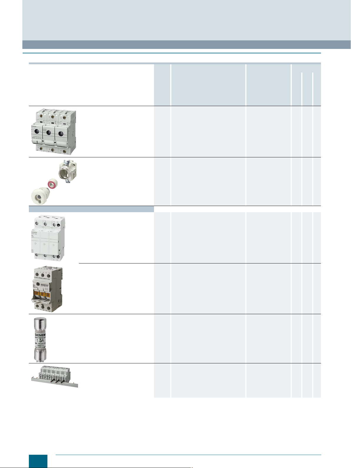
NEOZED fuse systems 8 MINIZED switch disconnectors, bases,
DIAZED fuse systems
fuse links from 2 A to 63 A of operational class gG and accessories.
Everything you need for a complete
system.
15 Fuse links from 2 A to 100 A in various
operational classes, base versions with
classic screw base connections.
A widely used fuse system.
Fuse system:
IEC 60269-3;
DIN VDE 0636-3
Safety switching
devices
IEC/EN 60947-3
DIN VDE 0638;
DIN EN 60947-3
(VDE 0660-107)
IEC 60269-3;
DIN VDE 0635;
DIN VDE 0636-3;
CEE 16
Non-residential
buildings
Residential
buildings
✓ ✓ ✓
✓ ✓ ✓
Industry
Cylindrical fuse systems
Cylindrical fuse links and cylindrical
fuse holders
Fuse holders in size 10 x 38 mm and
Class CC
Class CC fuse systems
Busbar systems
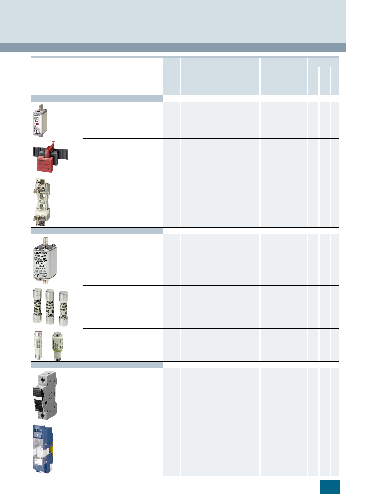
24 Line protection or protection of
switching devices.
The fuse holders with touch protection
ensure the safe "no-voltage"
replacement of fuse links.
Auxiliary switches can be retrofitted.
32 For installing fused loaded motor starter
combinations.
36 These comply with American standard
and have UL and CSA approval, for
customers exporting OEM products
and mechanical engineers.
Modern design with touch protection
according to BGV A3 for use in "branch
circuit protection".
40 Busbars for NEOZED fuse bases,
NEOZED fuse disconnectors, MINIZED
switch disconnectors, DIAZED fuse
systems and for the cylindrical fuse
systems.
Compact cylindrical fuse holders for
busbars.
IEC 60269-1, -2, -3;
NF C 60-200;
NF C 63-210, -211;
NBN C 63269-2,
CEI 32-4, -12
Fuse holders:
File No. E171267
IEC 60269-1, -2;
IEC 60947-4;
UL 4248-1,
File No. E171267
CSA 250269, 6225-01
Auxiliary switches:
UL 508,
File No. E334003
Fuse holders:
UL 4248-1, E171267
CSA 22.2
Fuse links:
UL 248-4,
File No. E258218,
CSA 231237, 1422-02
and 1422-82
DIN EN 60439-1
(VDE 0660-500)
UL 4248-1, E337131
✓ ✓ ✓
✓ -- ✓
✓ ✓ ✓
✓ ✓ ✓
2
Siemens · 10/2015
Page 5
© Siemens AG 2016
Fuse Systems
Introduction
Devices Page Application Standards Used in
Non-residen-
tial buildings
3NA, 3ND LV HRC fuse systems
LV HRC fuse links 45 Fuse links from 2 A to 1250 A for
selective line protection and system
protection in non-residential buildings,
industry and power utilities.
IEC 60269-1, -2;
EN 60269-1;
DIN VDE 0636-2;
CSA 16325 - 1422-02
✓ ✓ ✓
Residential
buildings
Industry
LV HRC signal detectors 68 Signal detectors for when a fuse is
LV HRC fuse bases and
accessories
SITOR semiconductor fuses
LV HRC design 78 Fuse links in LV HRC design and a
Cylindrical fuse design
NEOZED and DIAZED design
tripped on all LV HRC fuse links with
combination or front indicators with
non-insulated grip lugs.
Plus the comprehensive accessory
range required for LV HRC fuse
systems.
69 Fuse bases for screw or snap-on
mounting onto standard mounting rails,
available as 1-pole or 3-pole version.
huge variety of models support a wide
range of applications from 500 V to
1500 V and 150 A to 1600 A.
Fuses with slotted blade contacts,
bolt-on links or female thread, and
special designs.
147 Fuse links, fuse holders – usable as
fuse switch disconnectors and fuse
bases up to 600/690 V AC and
400/700 V DC from 1 A to 100 A
in the sizes 10 × 38 mm, 14 × 51 mm
and 22 × 58 mm.
168 NEOZED fuse links for 400 V AC and
250 V DC and DIAZED for 500 V AC
and 500 V DC.
-- ✓ ✓ ✓
IEC 60269-1, -2;
EN 60269-1;
DIN VDE 0636-2
UL 4248-1,
File No. E171267-IZLT2
(only downstream from
branch circuit protection)
CSA C22.2
No. 4248.1-07
UL 4248-13, File No.
E167357-JFHR2
Fuse links:
UL 4248-13, File No.
E167357-JFHR2
CSA 248170, 1422-30
Fuse holders:
UL 4248-1, File No.
E171267- IZLT
CSA 248170, 6225-01
-- -- -- ✓
✓ ✓ ✓
-- -- ✓
-- -- ✓
Photovoltaic fuses
PV cylindrical fuses 186 Fuses with a rated voltage of
PV cumulative fuses
1000 V DC and operational class gPV
for the protection of photovoltaic
modules, their connecting cables
and other components.
191 Fuses with a rated voltage of 1000 V
and 1500 V DC, a rated current of 63 A
to 630 A and operational class gPV for
the protection of connecting cables and
other components.
IEC 60269-6 ✓ ✓ ✓
IEC60269-6 ✓ ✓ ✓
Siemens · 10/2015
3
Page 6
Fuse Systems
Introduction
■
Overview
Rated voltage U
The rated voltage is the designated voltage of the fuse and is
used to determine its test conditions and operational voltage
limits.
For LV HRC and SITOR fuse links, the rated voltage is always the
rms value of an AC voltage.
For wind power plants and some industrial applications, a higher
voltage tolerance is demanded of the LV HRC and SITOR fuses
than the tolerance of +5 % defined in the standard. On request,
you can obtain a manufacturer's declaration for the rated voltage
of 690 V +10 %.
In the case of NEOZED and DIAZED fuse links, a distinction is
made between AC and DC voltage values.
Rated current I
The rated current of a fuse link is the designated current of the
fuse link and is the current up to which it can be continuously
loaded under prescribed conditions without adverse affects.
Rated frequency
The rated frequency is the frequency for which the fuse link
is rated with regard to power dissipation, current, voltage,
characteristic curve and breaking capacity.
Selectivity
Several fuses are usually connected in series in a system. Selectivity ensures that only the faulty electric circuit and not all operating processes are interrupted in a system in serious cases.
Siemens fuses of operational class gG, at an operational voltage
of up to 400 V AC and a ratio of 1:1.25, are interselective, i.e.
from rated current level to rated current level. This is achieved by
means of the considerably smaller band of scatter of ± 5 % of
the time/current characteristics, which far exceeds the demand
for a ratio of 1:1.6 specified in the standard.
It is therefore possible to use smaller conductor cross-sections
due to the lower rated currents.
Breaking capacity
The rated breaking capacity is the highest prospective shortcircuit current I
conditions.
A key feature of these fuses is their high rated breaking capacity
with the smallest footprint. The basic demands and circuit data
for tests – voltage, power factor, actuating angle, etc. – are
specified in both national (DIN VDE 0636) and international
(IEC 60269) regulations.
However, for a constant fail-safe breaking capacity, from the
smallest non-permissible overload current through to the highest
short-circuit current, a number of quality characteristics need to
be taken into account when designing and manufacturing fuse
links. These include the design of the fuse element with regard
to dimensions and punch dimension and its position in the
fuse body, as well as its compressive strength and the thermal
resistance of the body. The chemical purity, particle size and
the density of the quartz sand also play a key role.
The rated breaking capacity for AC voltage for NEOZED fuses –
and the majority of DIAZED fuses – is 50 kA, and in the case of
our LV HRC fuses (NH type), it is even 120 kA. The various type
ranges of SITOR semiconductor fuses have different switching
capacities ranging from 50 to 100 kA.
.
n
n
that the fuse link can blow under prescribed
p
© Siemens AG 2016
Faster arcing and precise arc quenching are the requirements for a
reliable breaking capacity.
Operational classes
Fuses are categorized according to function and operational
classes. The first letter defines the function class and the second
the object to be protected:
1st letter
a = Partial range protection
Fuse links that carry currents at least up to their specified rated
current and can switch currents above a specific multiple of their
rated current up to their rated breaking current.
g = Full range protection
Fuse links that can continuously carry currents up to at least their
specified rated current and can switch currents from the smallest melting current through to the breaking current. Overload
and short-circuit protection.
2nd letter
G = Cable and line protection
M = Switching device protection in motor circuits
R, S = Semiconductor protection/thyristor protection
L = Cable and line protection
B = Mine equipment protection
Tr = Transformer protection
The designations "slow" and "quick" still apply to DIAZED fuses.
These are defined in IEC/CEE/DIN VDE.
In the case of "quick" characteristics, the fuse blows in the breaking range faster than those of operational class gG.
In the case of DIAZED fuse links for DC railway network protection, the "slow" characteristic is particularly suitable for switching
off direct currents with greater inductance. Both characteristics
are also suitable for the protection of cables and lines.
Full range fuses (gG, gR, quick, slow) reliably break the
current in the event of non-permissible overload and shortcircuit currents.
Partial range fuses (aM, aR) exclusively serve short-circuit
protection.
(
accompanied fuses):
(
general purpose fuses):
(general applications)
(for protection of motor circuits)
(for protection of rectifiers)
(in acc. with the old, no longer valid DIN VDE)
4
Siemens · 10/2015
Page 7
t
v
i
2
dt
I
p
2
------------=
I201_06997b
P
c
sL
U
t
tt
t
c
:
Maximum let-through current
t
s
:
Pre-arcing time
t
L
:
Arcing time
P
:
Peak short-circuit current
Us: Arc voltage
© Siemens AG 2016
The following operational classes are included in the product
range:
gG (DIN VDE/IEC) = Full-range cable and line protection
aM (DIN VDE/IEC) = Partial-range switching device
protection
aR (DIN VDE/IEC) = Partial-range semiconductor protection
gR (DIN VDE/IEC) = Full-range semiconductor protection
gS (DIN VDE/IEC) = Full-range semiconductor protection
and cable and line protection
quick (DIN VDE/IEC/CEE) = Full-range cable and
line protection
slow (DIN VDE) = Full range cable and line protection
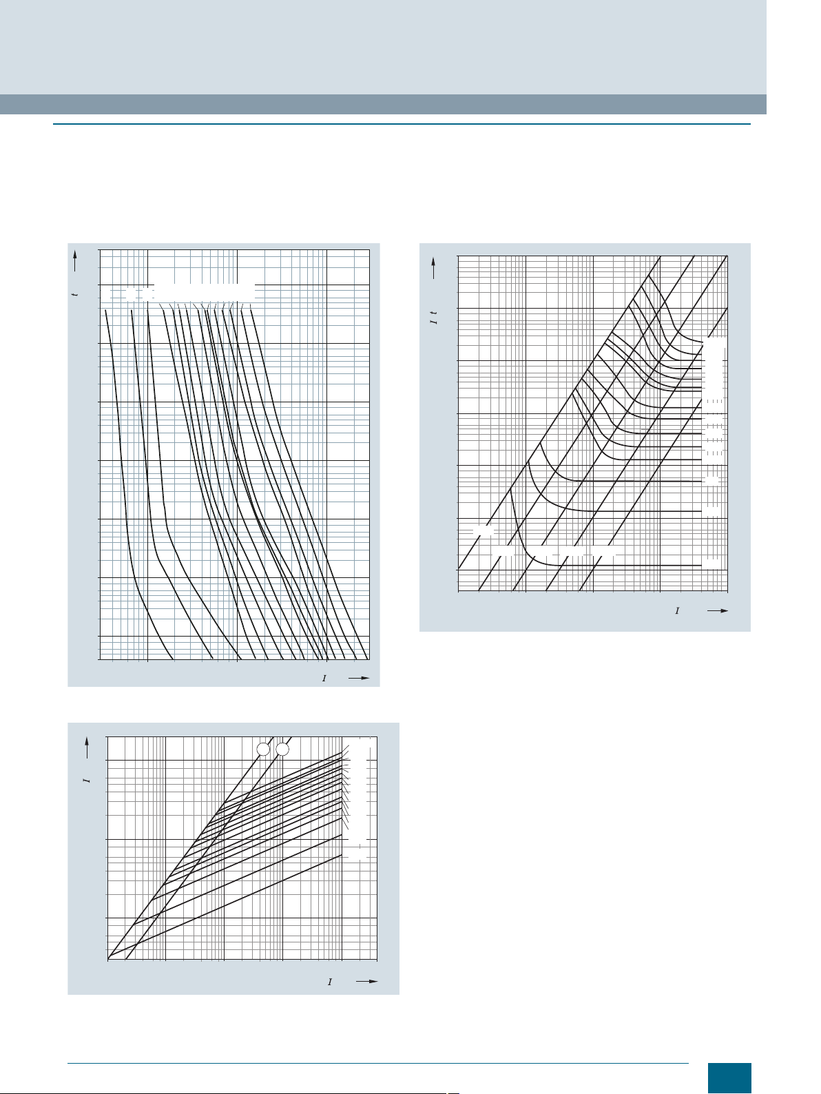
Characteristic curves (time/current characteristic curves)
The time/current characteristic curve specifies the virtual time
(e.g. the melting time) as a function of the prospective current
under specific operating conditions.
Melting times of fuse links are presented in the time/current
diagrams with logarithmic subdivision as a function of their currents. The melting time characteristic curve extends from the
lowest melting current, which still just causes the melting conductor to melt asymptotically to the I
values in the range of higher short-circuit currents, which specifies the constant melting heat value I
the time/current characteristics diagrams omit the I
9
10
[s]
t
5
10
a
2
t line of equal Joulean heat
2
t. For the sake of simplicity,
2
t lines (c).
Fuse Systems
Introduction
Virtual time t
The virtual time is the time span calculated when an I2t value is
divided by the square of the prospective current:
The time/current characteristic curve specifies the prospective
current I
Prospective short-circuit current I
The prospective short-circuit current is the rms value of the
line-frequency AC component, or the value of direct current to
be expected in the event of a short-circuit occurring downstream
of the fuse, were the fuse to be replaced by a component of
negligible impedance.
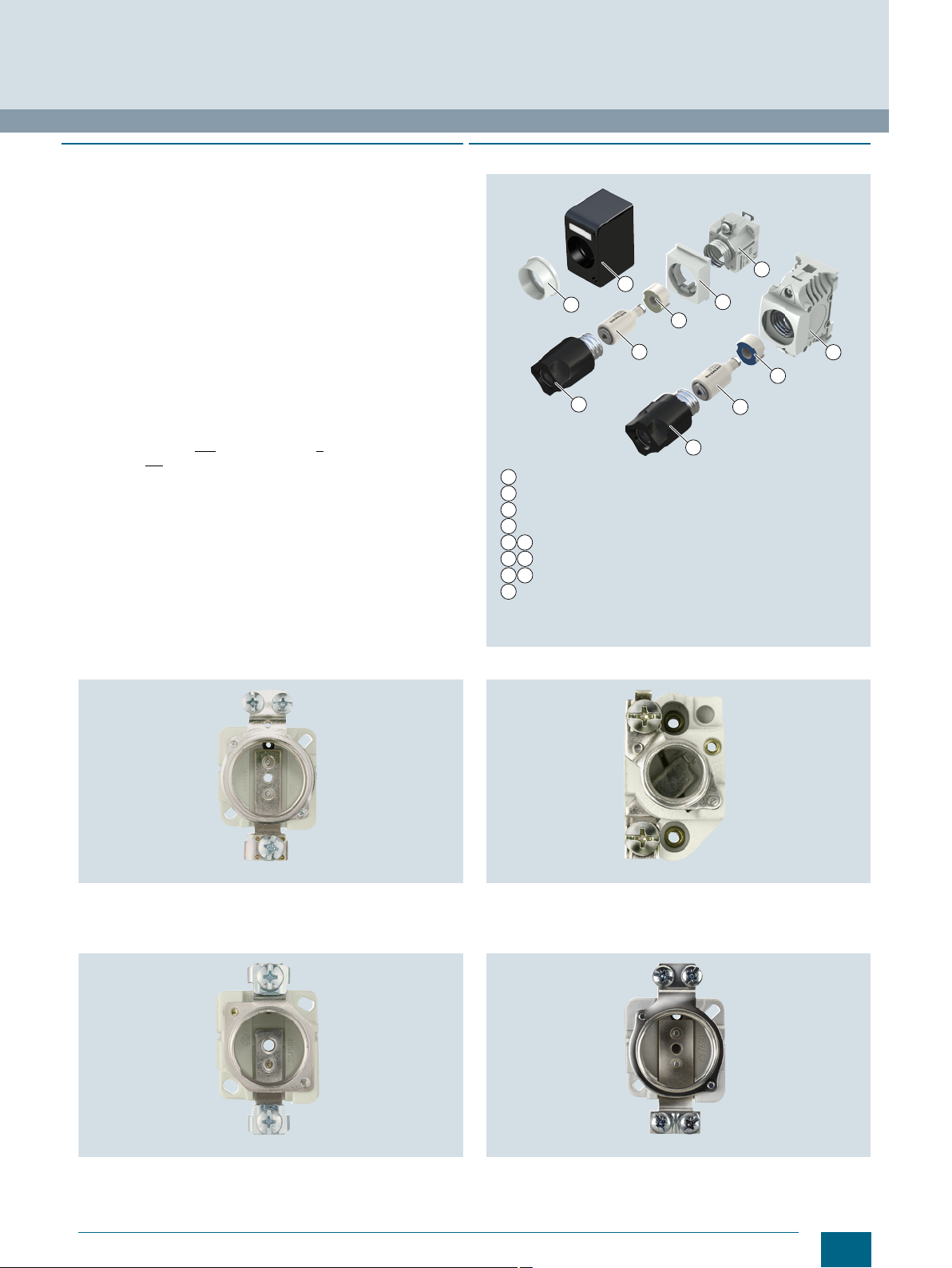
Let-through current characteristic curves
The let-through current characteristic curve specifies the value
of the let-through current at 50 Hz as a function of the prospective current.
The let-through current I
of the current reached during a switching operation of a fuse.
The fuse element of the fuse links melts so quickly at very high
currents that the surge short-circuit current I
occurring. The highest instantaneous value of the current
reached during the breaking cycle is called the let-through
current I
diagrams, otherwise known as let-through current diagrams.
v
and the virtual melting time tvs.
p
p
is the maximum instantaneous value
c
is prevented from
p
. The current limits are specified in the current limiting
c
1
10
1234
10 10 10 10
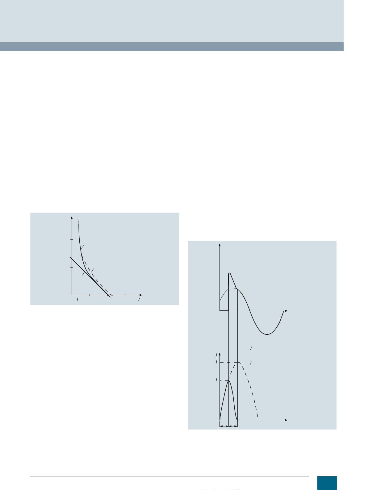
General representation of the time/current characteristic curve of a fuse
link of operational class gL/gG
I
: Smallest melting current
min
a: Melting time/current characteristic
b: Breaking time characteristic curve
2
c: I
t line
min
b
c
I201_06996a
[A]
The curve of the characteristic depends on the outward heat
transfer from the fuse element. DIN VDE 0636 specifies tolerance-dependent time/current ranges within which the characteristic curves of the fuse must lie. Deviations of ± 10 % are permissible in the direction of the current axis. With Siemens LV HRC
fuse links of operational class gG, the deviations work out at
less than ± 5 %, a mark of our outstanding production accuracy.
For currents up to approx. 20 I
teristic curves are the same as the breaking time characteristic
curves. In the case of higher short-circuit currents, the two
characteristic curves move apart, influenced by the respective
arc quenching time.
The difference between both lines (= arc quenching time) also
, the melting time/current charac-
n
depends on the power factor, the operational voltage and the
breaking current.
The Siemens characteristic curves show the mean virtual melting time characteristic curves recorded at an ambient temperature of (20 ± 5) °C. They do not apply to preloaded fuse links.
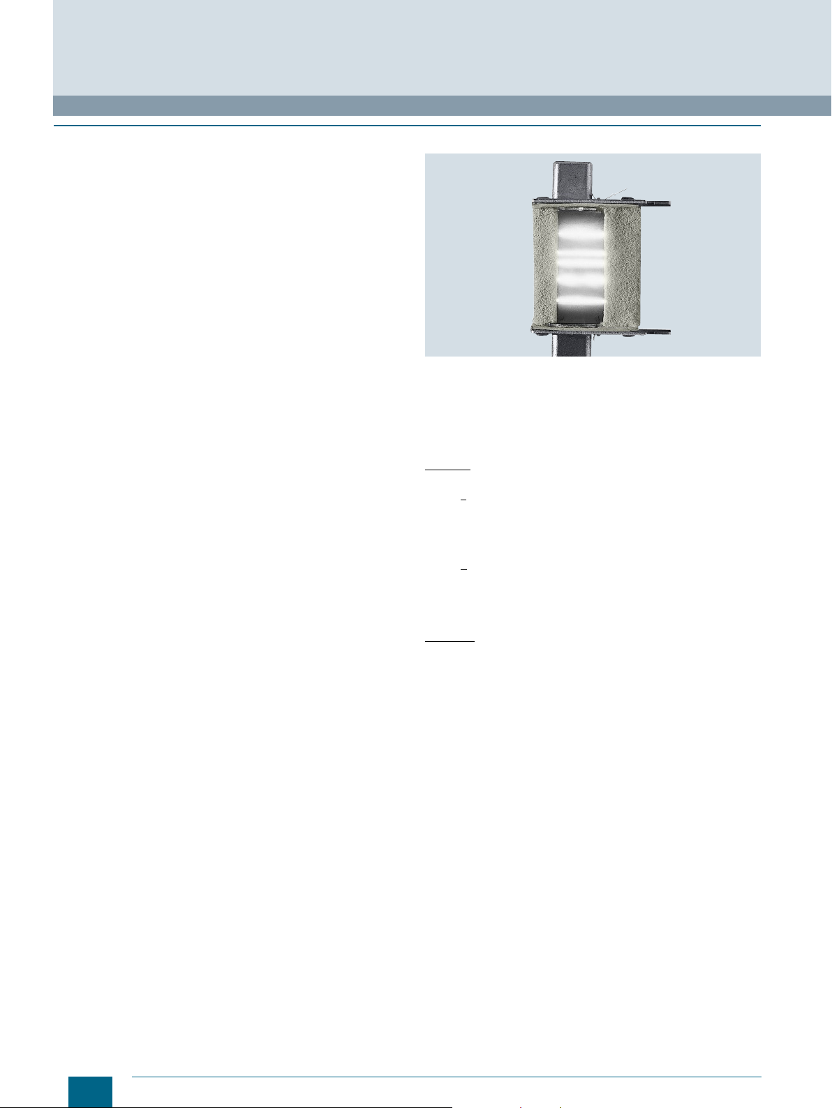
Oscillograph of a short-circuit current breaking operation through
a fuse link
Siemens · 10/2015
5
Page 8
I2ti2td
t
0
t
1
=
© Siemens AG 2016
Fuse Systems
Introduction
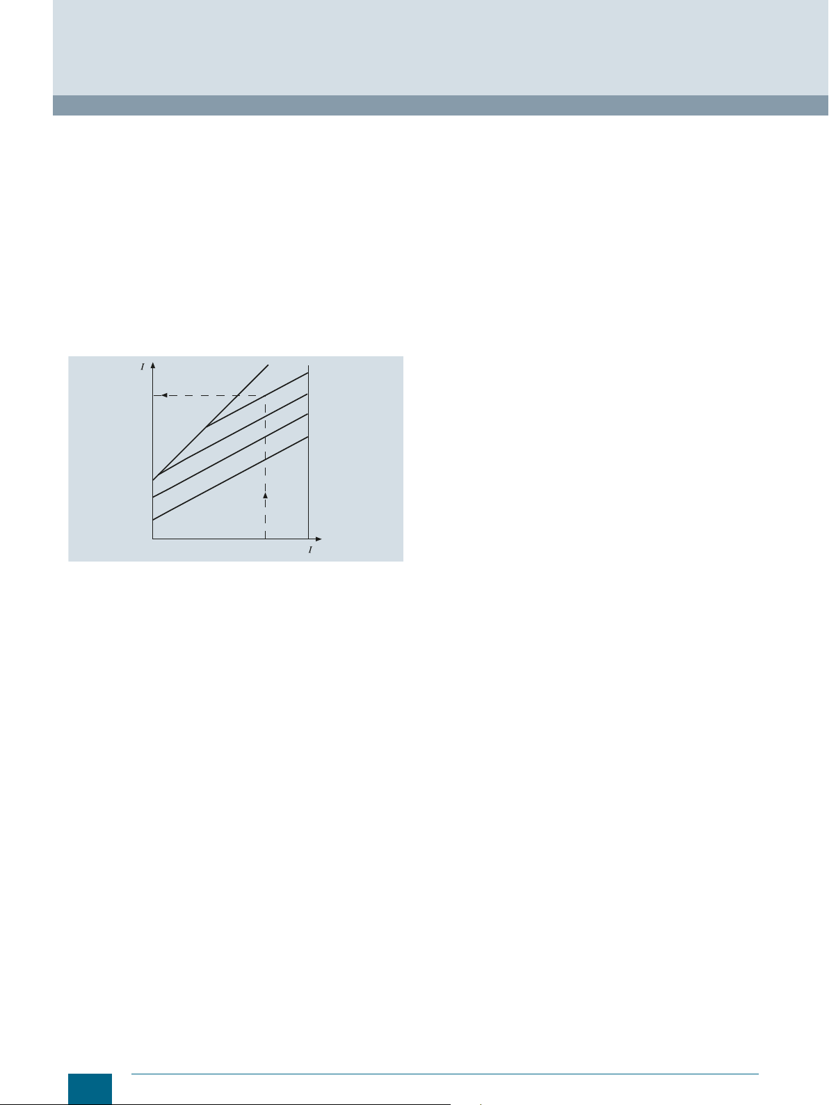
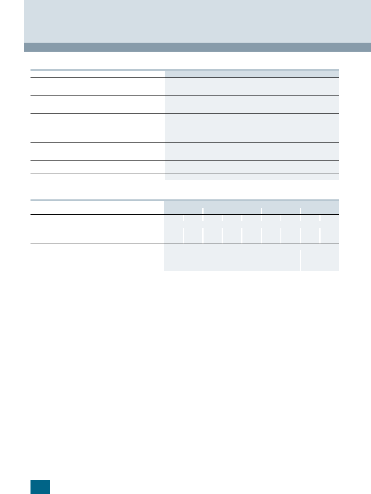
Current limiting
As well as a fail-safe rated breaking capacity, the current-limiting
effect of a fuse link is of key importance for the cost effectiveness
of a system. In the event of short-circuit breaking by a fuse, the
short-circuit current continues to flow through the network until
the fuse link is switched off. However, the short-circuit current
is only limited by the system impedance.
The simultaneous melting of all the bottlenecks of a fuse element
produce a sequence of tiny partial arcs that ensure a fast breaking operation with strong current limiting. The current limitation is
also strongly influenced by the production quality of the fuse –
which in the case of Siemens fuses is extremely high. For example, an LV HRC fuse link, size 2 (224 A) limits a short-circuit current with a possible rms value of approximately 50 kA to a letthrough current with a peak value of approx. 18 kA. This strong
current limitation provides constant protection for the system
against excessive loads.
c
100 A
50 A
10 A
6 A
Rated power dissipation
Rated power dissipation is the power loss during the load of
a fuse link with its rated current under prescribed conditions.
The cost effectiveness of a fuse depends largely on the rated
power dissipation (power loss). This should be as low as possible and have low self-heating. However, when assessing the
power loss of a fuse, it must also be taken into account that there
is a physical dependence between the rated breaking capacity
and the rated power dissipation. On the one hand, fuse elements
need to be very thick in order to achieve the lowest possible
resistance value, on the other, a high rated breaking capacity
requires the thinnest possible fuse elements in order to achieve
reliable arc quenching.
Siemens fuses have the lowest possible rated power dissipation while also providing the highest possible load breaking
reliability.
These values lie far below the limit values specified in the r
egulations. This means a low temperature rise, reliable breaking
capacity and high cost effectiveness.
2
I
t value
2
t value (joule integral) is the integral of the current squared
The I
over a specific time interval:
I201_06998a
eff
Current limiting diagram
Let-through current diagram of LV HRC fuse links, size 00
Operational class gL/gG
Rated currents 6 A, 10 A, 50 A, 100 A
Legend
= Virtual melting time
t
vs
I
= Max. let-through current
c
=rms value of the prospective short-circuit current
I
rms
2
I
ts= Melting I2t value
2
I
ta=Breaking I2t value
= Rated current
I
n
P
= Rated power dissipation
v
= Temperature rise
k
= Correction factor for I2t value
A
= Recovery voltage
U
w
Û
= Peak arc voltage
s
I
= Peak short-circuit current
p
$ = Peak short-circuit current with largest DC component
% = Peak short-circuit current without DC component
U =Voltage
i =Current
t
= Melting time
s
= Arc quenching time
t
L
Specifies the I
the breaking cycle ((I
2
I
t value). The melting I2t value, also known as the total I2t value
or breaking I
2
t values for the melting process (I2ts) and for
2
tA, , – sum of melting and quenching
2
t value, is particularly important when dimension-
ing SITOR semiconductor fuses. This value depends on the
voltage and is specified with the rated voltage.
Peak arc voltage Û
s
The peak arc voltage is the maximum value of the voltage
that occurs at the connections of the fuse link during the arc
quenching time.
Residual value factor RV
The residual value factor is a reduction factor for determining the
permissible load period of the fuse link with currents that exceed
the permissible load current I
is applied when dimensioning SITOR semiconductor fuses.
’ (see rated current In). This factor
n
Varying load factor VL
The varying load factor is a reduction factor for the rated current
with varying load states. This factor is applied when dimensioning SITOR semiconductor fuses.
Recovery voltage U
w
The recovery voltage (rms value) is the voltage that occurs at the
connections of a fuse link after the power is cut off.
6
Siemens · 10/2015
Page 9
■
More information
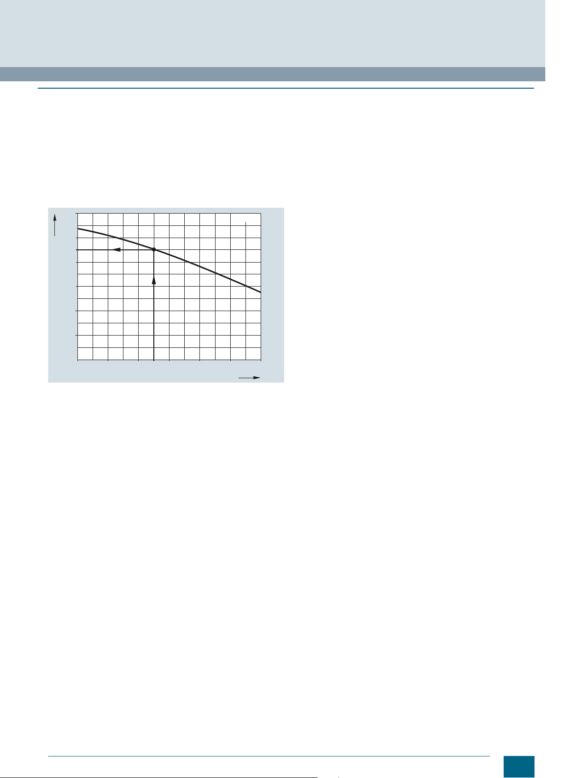
Load capability with increased ambient temperature
The time/current characteristic curve of the NEOZED/DIAZED
and LV HRC fuse links is based on an ambient temperature of
20 °C ± 5 °C in accordance with DIN VDE 0636. When used in
higher ambient temperatures (see diagram) a reduced load-car-
rying capacity must be planned for. At an ambient temperature
of 50 °C, for example, an LV HRC fuse link should be dimensioned for only 90 % of the rated current. While the short-circuit
behavior is not influenced by an increased ambient temperature,
it is influenced by overload and operation at rated value.
120
100
90
80
60
40
Current carrying capacity [%]
20
0
Influence of the ambient temperature on the load capability of
NEOZED/DIAZED and LV HRC fuses of operational class gG with
natural convection in the distribution board.
5020 40 60 80 100 1200
Ambient temperature [°C]
I201_06648c
© Siemens AG 2016
Assignment of cable and line protection
When gG fuses are assigned for cable and line protection
against overloading, the following conditions must be met in
order to comply with DIN VDE 0100 Part 430:
(1) I
= In = Iz (rated current rule)
B
= 1.45 × Iz (tripping rule)
(2) I
2
: Operational current of electrical circuit
I
B
: Rated current of selected protective device
I
n
: Permissible current carrying capacity of the cable or line
I
z
under specified operating conditions
I
: Tripping current of the protective device under specified
2
operating conditions ("high test current").
These days, the factor 1.45 has become an internationally
accepted compromise of the protection and utilization ratio of a
line, taking into account the breaking response of the protective
device (e.g. fuse).
In compliance with the supplementary requirements for
DIN VDE 0636, Siemens fuse links of operational class gG
comply with the following condition:
"Load breaking switching with I
test duration under special test conditions in accordance with
the aforementioned supplementary requirements of
DIN VDE 0636".
This therefore permits direct assignment.
Fuse Systems
Introduction
=1.45 × In during conventional
2
Siemens · 10/2015
7
Page 10
Fuse Systems
NEOZED Fuse Systems
NEOZED fuse links
■
Overview
The NEOZED fuse system is primarily used in distribution technology and industrial switchgear assemblies. The system is easy
to use and is also approved for domestic installation.
The MINIZED switch disconnectors are primarily used in switchgear assemblies and control engineering. They are approved for
switching loads as well as for safe switching in the event of short
circuits. The MINIZED D02 is also suitable for use upstream of
the meter in household applications in compliance with the
recommendations of VDEW according to TAB 2007.
© Siemens AG 2016
Due to its compact design, the MINIZED D01 fuse switch
disconnector is primarily used in control engineering.
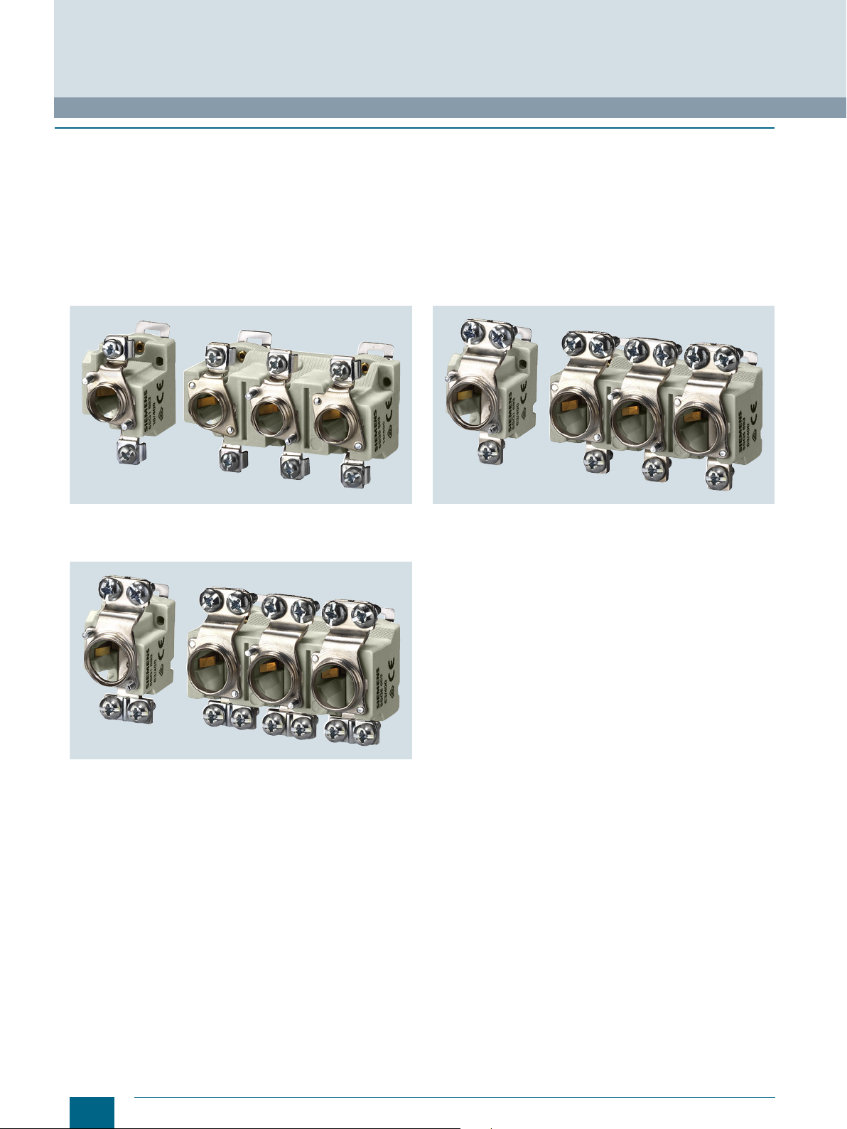
The NEOZED fuse bases are the most cost-effective solution for
using NEOZED fuses. All NEOZED bases must be fed from the
bottom to ensure that the threaded ring is insulated during removal of the fuse link. The terminals of the NEOZED bases are
available in different versions and designs to support the various
installation methods.
Fuse bases D01 with terminal version BB
• Incoming feeders, clamp-type terminal B
• Outgoing feeders, clamp-type terminal B
Fuse bases D02, with terminal version SS
• Incoming feeders, saddle terminal S
• Outgoing feeders, saddle terminal S
Fuse bases D02, with terminal version KS
• Incoming feeders, screw head contact K
• Outgoing feeders, saddle terminal S
8
Siemens · 10/2015
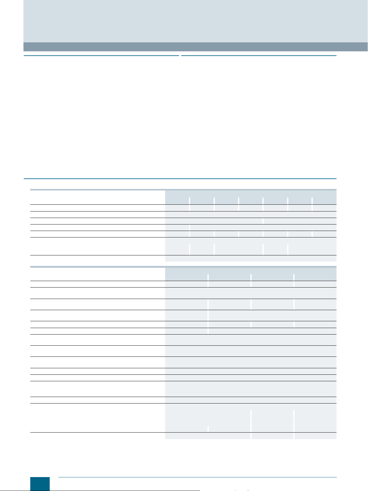
Page 11
■
Technical specifications
Standards
Operational class
Rated voltage U
Rated current I
Rated breaking capacity kA AC
Non-interchangeability
Resistance to climate °C
Ambient temperature °C
n
n
NEOZED fuse links
5SE2
IEC 60269-3; DIN VDE 0636-3
gG
VAC 400
VDC
A 2...100
kA DC
250
50
8
Using adapter sleeves
Up to 45 at 95 % rel. humidity
-5 to +40, humidity 90 % at 20
© Siemens AG 2016
Fuse Systems
NEOZED Fuse Systems
NEOZED fuse links
MINIZED
switch disconnectors
D02
5SG71
Standards
Main switch characteristic,
EN 60204-1
Insulation characteristic
EN 60664-1
Rated voltage U
•1P VDC
• 2P in series V DC
Rated current I
Rated insulation voltage VAC
Rated impulse withstand voltage KV AC
Overvoltage category
Utilization category acc. to VDE 0638
•AC-22 A 63 16 --
Utilization category acc. to EN 60947-3
•AC-22A A -- 16 --
•AC-22B A
•AC-23B A
• DC-22 B A
Sealable
When switched on
Mounting position
Reduction factor of I
• Side-by-side mounting 0.9 --
• On top of one another, with vertical standard
mounting rail
Degree of protection acc. to IEC 60529
Terminals
With touch protection acc. to BGV A3
Ambient temperature °C
Terminal versions
Conductor cross-sections
• Solid and stranded mm
• Flexible, with end sleeve mm
• Finely stranded, with end sleeve mm
Tightening torque Nm
1)
Degree of protection IP20 is tested according to regulations using a
straight test finger (from the front), with the device mounted and equipped
with a cover, housing or some other enclosure.
n
n
with 18 pole
n
VAC 230/400, 240/415 400
A 63 16 16 63 100 16/63 16/63
DIN VDE 0638;
EN 60947-3
(VDE 0660-107)
IEC/EN 60947-3
Yes -- --
Yes -- --
65 48 250
130 110 250
500 400 --
6 2.5 --
IV IV --
63 -- --
35 -- --
63 -- --
Yes Yes, with sealable screw caps
Any, preferably vertical
0.87 --
IP20, with connected conductors
Yes No Ye s
-5 to +40, humidity 90 % at 20
-- -- B K, S K/S -- --
2
1.5 ... 35 1.5 ... 16 1.5 ... 4 1.5 ... 25 10 ... 50 0.75 ... 35 1.5 ... 35
2
1.5 ... 35 1.5 1.5 1.5 10 -- --
2
-- -- 0.75 ... 25 -- -- -- --
2.5 ... 3 2.5 1.2 2 3.5/2.5 3.5 3
MINIZED fuse
switch disconnectors
D01
5SG76
Fuse bases,
made of ceramic
D01
5SG15
5SG55
IEC 60269-3; DIN VDE 0636-3
1)
D02
5SG16
5SG56
D03
5SG18
Comfort
bases
D01/02
5SG1. 01
5SG5.01
Fuse bases
5SG1. 30
5SG1. 31
5SG5.30
Siemens · 10/2015
9
Page 12

214
3
54
214
3
81
6
5
214
3
108
65N
N
70
44
45
5
90
I2_12122
81
27
79
70
44
55
5
90
45
I201_17072
246
135
I201_07988a
18 36 54 72
644
64
107
45
88
70
83
45
64
446,2
I2_12123
I201_07536b
71,5
58,7
45
26,6 79,8
4
44
47,2
59,2
Protective
caps
© Siemens AG 2016
Fuse Systems
NEOZED Fuse Systems
NEOZED fuse links
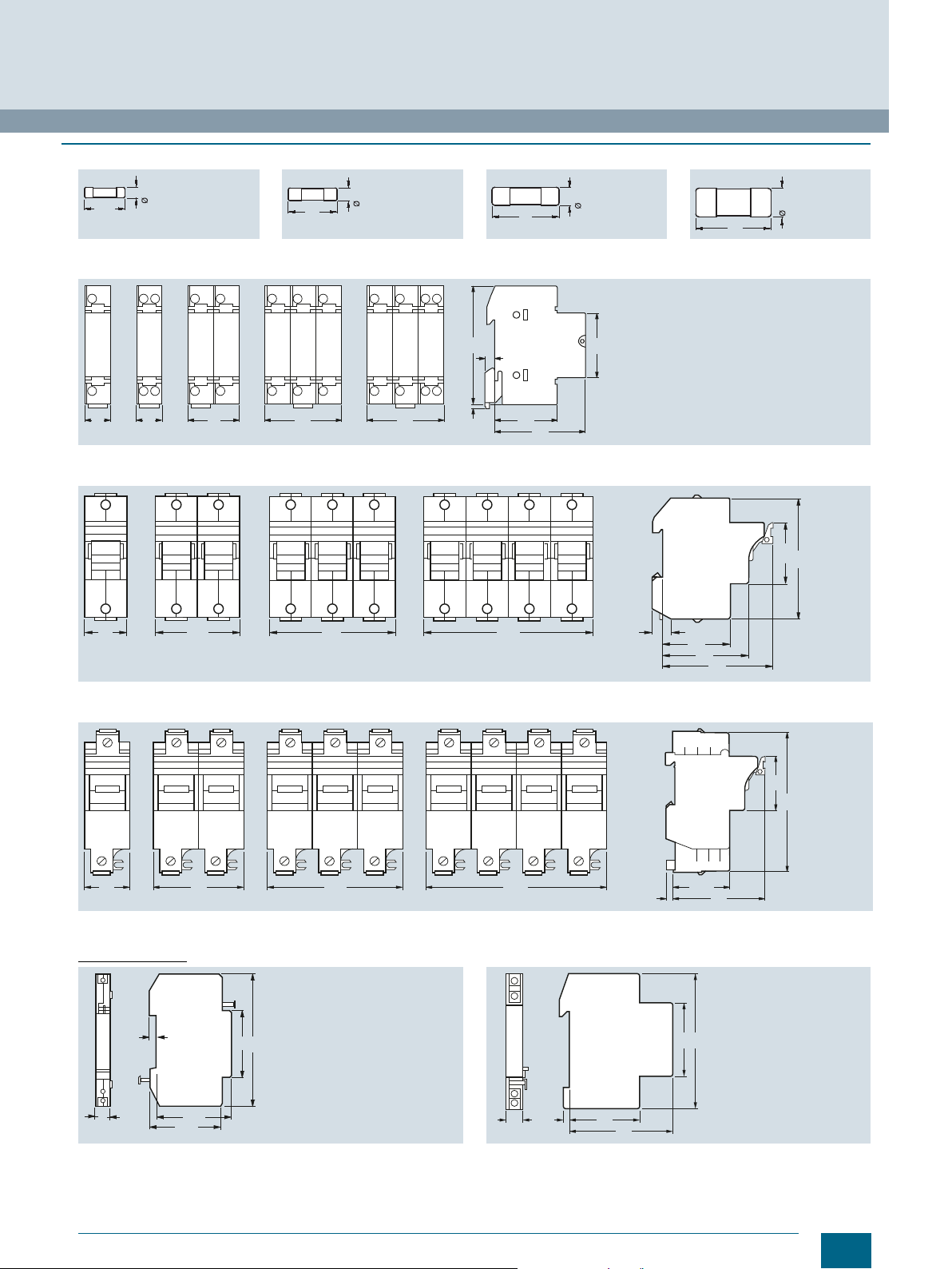
■
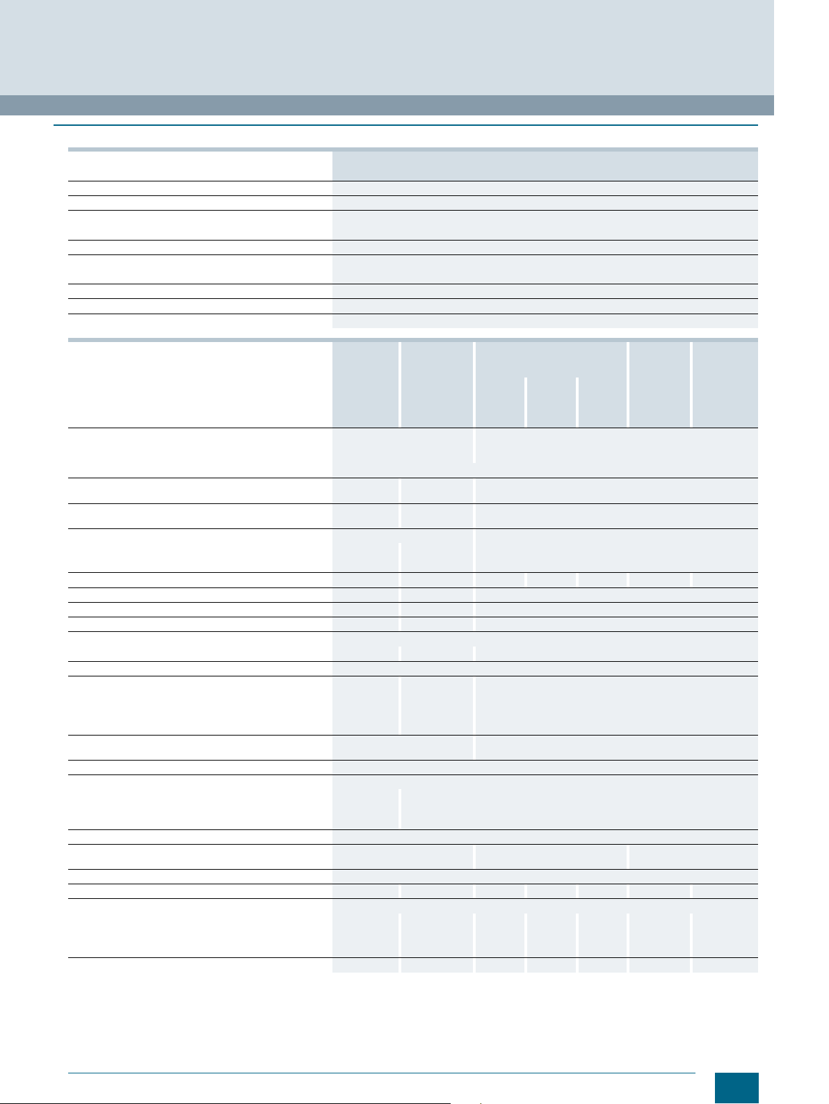
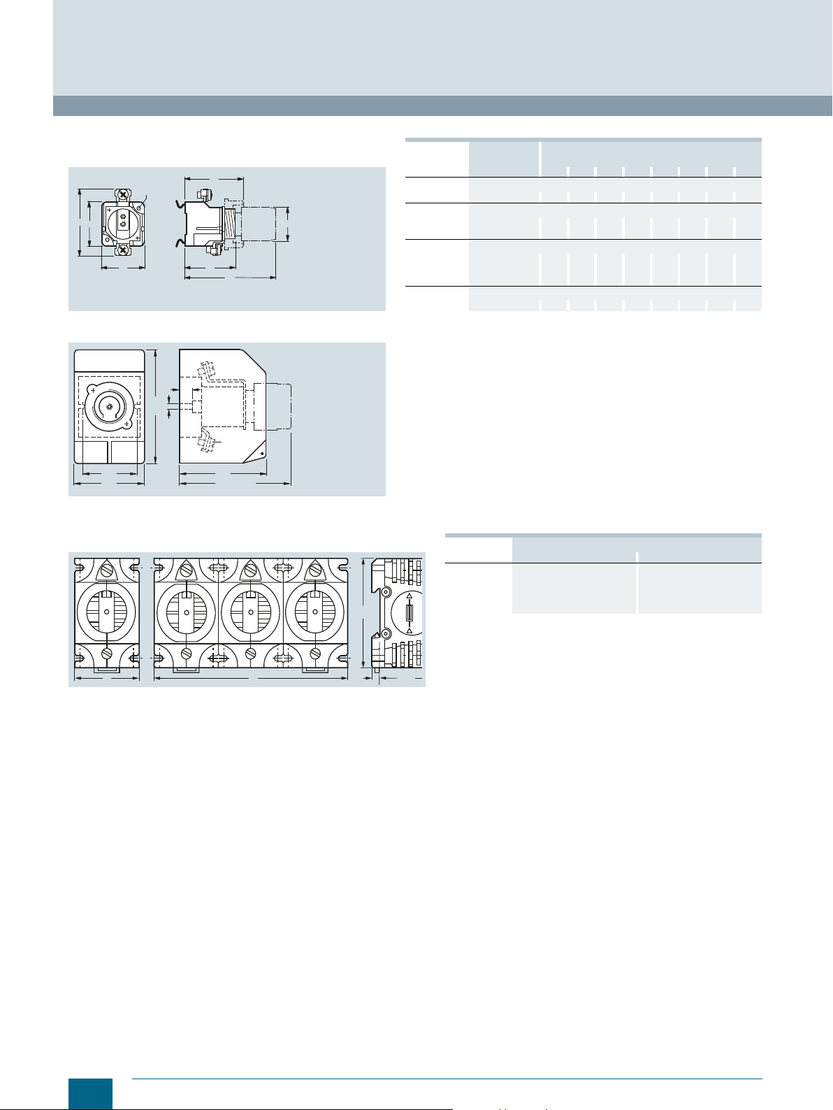
Dimensional drawings
5SG71.3 MINIZED D02 switch disconnectors, with draw-out technology
1P 1P+N 2P 3P 3P+N
Locking cap for MINIZED D02 switch disconnectors
5SG76 MINIZED D01 fuse switch disconnectors, with draw-out technology
1P 1P+N, 2P 3P 3P+N
Fuse bases with touch protection BGVA3 (VBG4), molded plastic
Sizes D01/D02, with combined terminal, can be busbar mounted With cover
5SG1301,
5SG1701
10
5SG5301,
5SG5701
Siemens · 10/2015
5SG1330,
5SG1331,
5SG1730,
5SG1731
5SG5330,
5SG5730
Page 13
NEOZED fuse bases made of ceramic
a
i
e
c
d
b
h
g
k
I201_06258b
screw cap
touch
protection
cover
I2_07537
71,5
45
26,6
79,8
16
I201_06206
45
21
1227
70
18
I201_06207
60
45
45
13
Sizes D01/D02/D03
5SG15 5SG55
© Siemens AG 2016
Fuse Systems
NEOZED Fuse Systems
NEOZED fuse links
Typ e Versio n Size Connection
Snap-on with cover
5SG1553
5SG1653
5SG1693
5SG5553
5SG5653
5SG5693
Snap-on without cover
5SG1595
5SG1655
5SG1695
5SG1812
5SG5555
5SG5655
5SG5695
Screw-on without cover
5SG1590
5SG1650
5SG1810
5SG5550
5SG5650
5SG5690
Legend
Connection type:
K = Screw head contact
B = Clamp-type terminal
S = Saddle terminal
1-pole D01 BB 26.8 36 40 56 70 23/26.5 54 -- --
3-pole D01 BB 80.8 36 40 56 70 23/26.5 54 -- --
1-pole D01 BB 26.8 36 40 56 70 23/26.5 54 -- --
3-pole D01 BB 80.8 36 40 56 70 23/26.5 54 -- --
1-pole D01 BB 26.8 36 40 56 70 23/26.5 54 20 22
3-pole D01 BB 80.8 36 40 56 70 23/26.5 54 74 22
D02 SS 26.8 36 41 56 70 23/26.5 59 -- -D02 KS 26.8 36 41 56 70 23/26.5 60 -- --
D02 SS 80.8 36 41 56 70 23/26.5 59 -- -D02 KS 80.8 36 41 56 70 23/26.5 60 -- --
D02 SS 26.8 36 41 56 70 23/26.5 59 -- -D02 KS 26.8 36 41 56 70 23/26.5 60 -- -D03 KS 44.9 50 44 54.5 76 44 86 -- --
D02 SS 80.8 36 41 56 70 23/26.5 59 -- -D02 KS 80.8 36 41 56 70 23/26.5 60 -- --
D02 SS 26.8 36 41 56 70 23/26.5 59 20 22
D03 KS 44.9 50 46 54.5 76 44 86 32 32
D02 SS 80.8 36 41 56 70 23/26.5 59 74 22
D02 KS 80.8 36 41 56 70 23/26.5 60 74 22
type
Dimensions
a b c d e g
BB = Clamp-type terminal at incoming feeder
SS = Saddle terminal at incoming feeder
KS = Screw head contact at incoming feeder
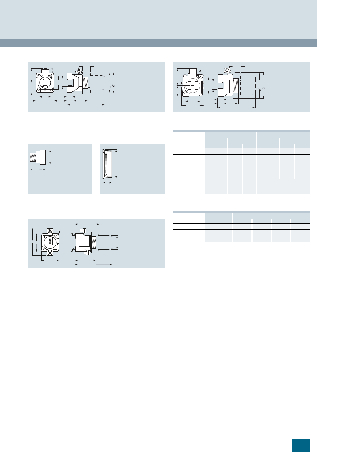
NEOZED covers made of molded plastic
NEOZED covers for NEOZED fuse bases, made of molded plastic
Clamp-type terminal at outgoing feeder
Saddle terminal at outgoing feeder
Saddle terminal at outgoing feeder
Not sealed/
sealed
h i k
5SH5244 (A1) 5SH5245 (A2)
NEOZED covers for NEOZED fuse bases, made of ceramic
I201_06209
81
5SH5251 (A4) and 5SH5253 (A10) 5SH5252 (A5) and 5SH5254 (A11) 5SH5233 (A6)
45
70
12
21
Siemens · 10/2015
11
Page 14
a
b
Size
n
A
D01/E14 2 ... 16
D02/E18 20 ... 63
D03/M30 80 ... 100
2
1
214
3
1212N
N
123456N
N
© Siemens AG 2016
Fuse Systems
NEOZED Fuse Systems
NEOZED fuse links
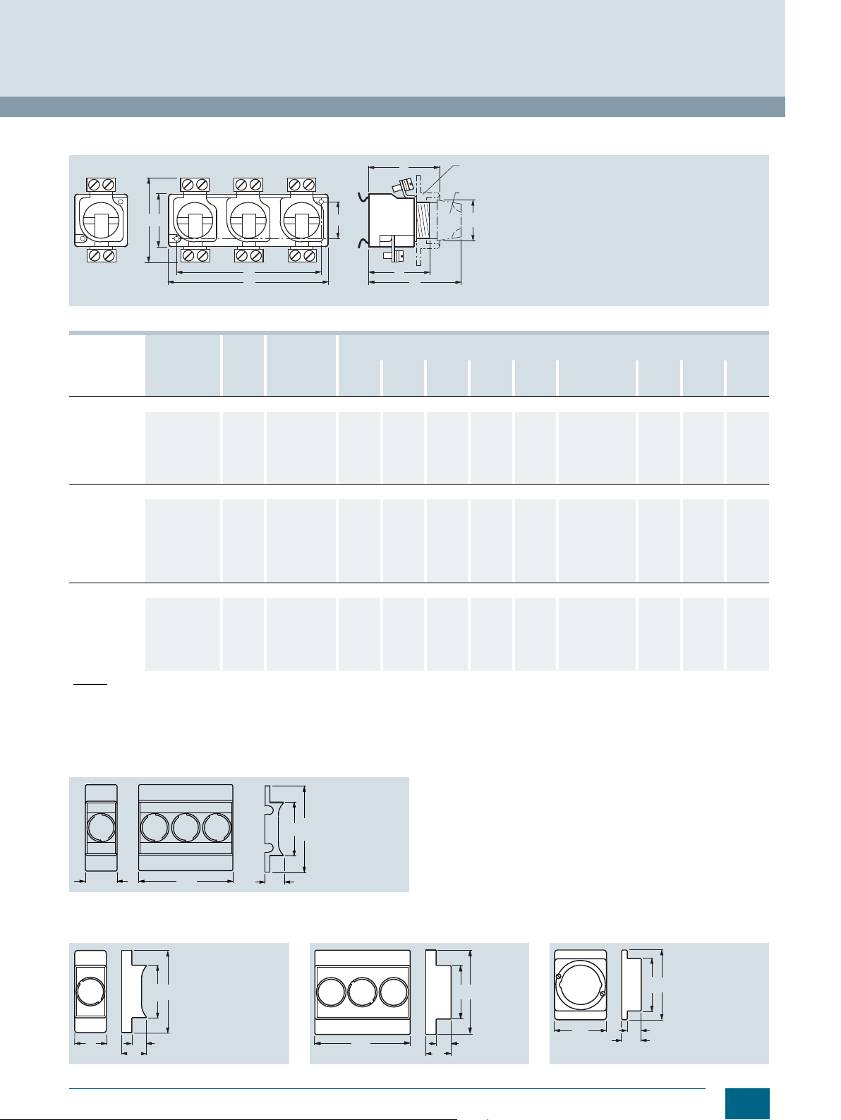
NEOZED screw caps
5SH4 Typ e Size Sealable For mounting
5SH4116 D01 -- 70 27.5 24
5SH4163
5SH4316
5SH4363
5SH4100
5SH4317
5SH4362
D02 -- 70 27.5 24
D01 ✔ 70 33 26.5
D02 ✔ 76 33 26.5
D03 -- 70 37 44
D01 -- 70 29.5 25
D02 -- 70 30.5 25
NEOZED fuse links
Size/thread Rated current in A Dimension
D01/E14 2...16 9.8 11 6 36
D02/E18
D03/M30
20 ... 63 13.8 15.3 10 36
80 ... 100 20.8 22.5 36 43
d
2min
depth
Dimension
d
3
Dimensions
a b
Dimension
d
4max
Dimension
h
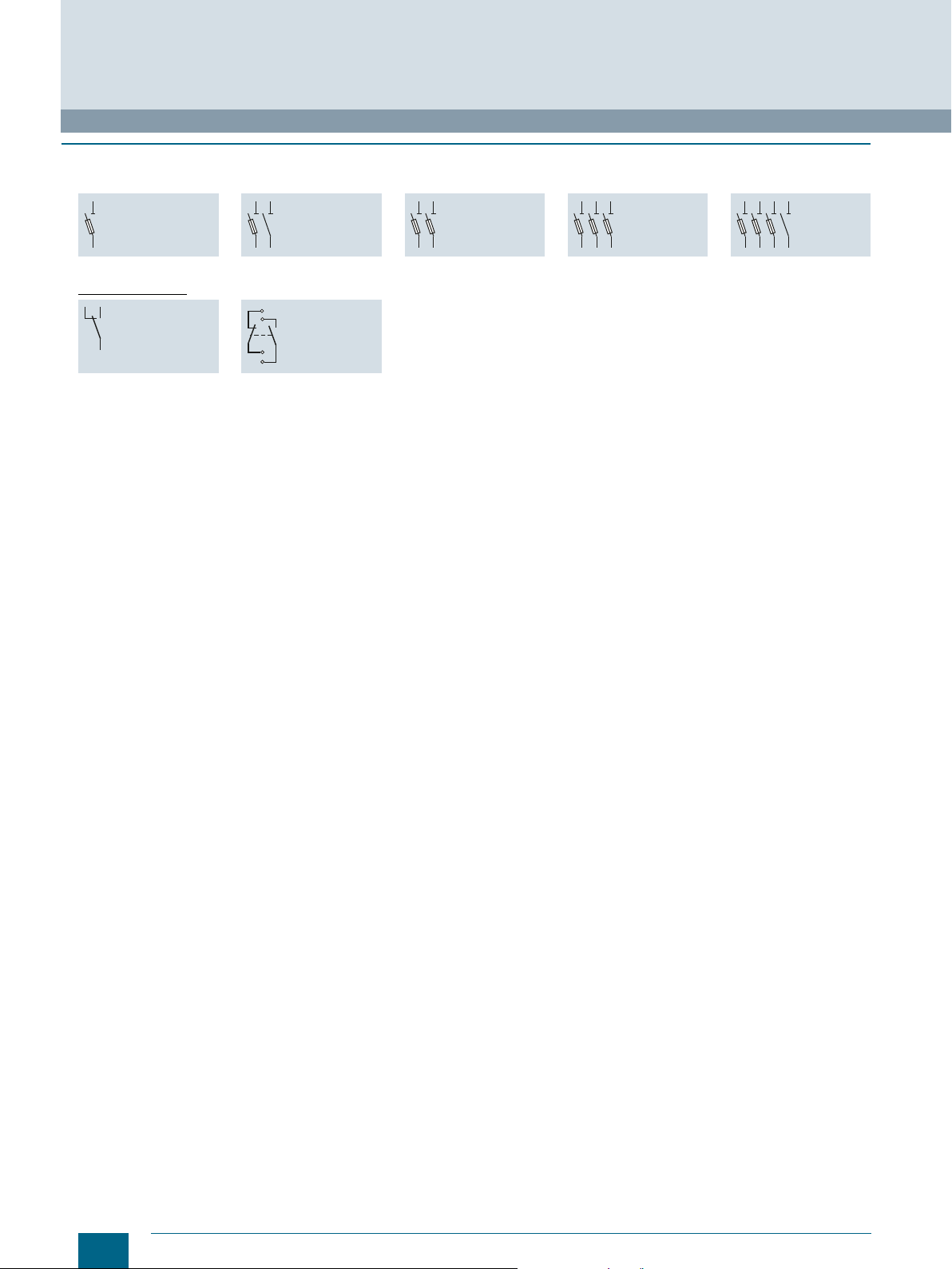
■
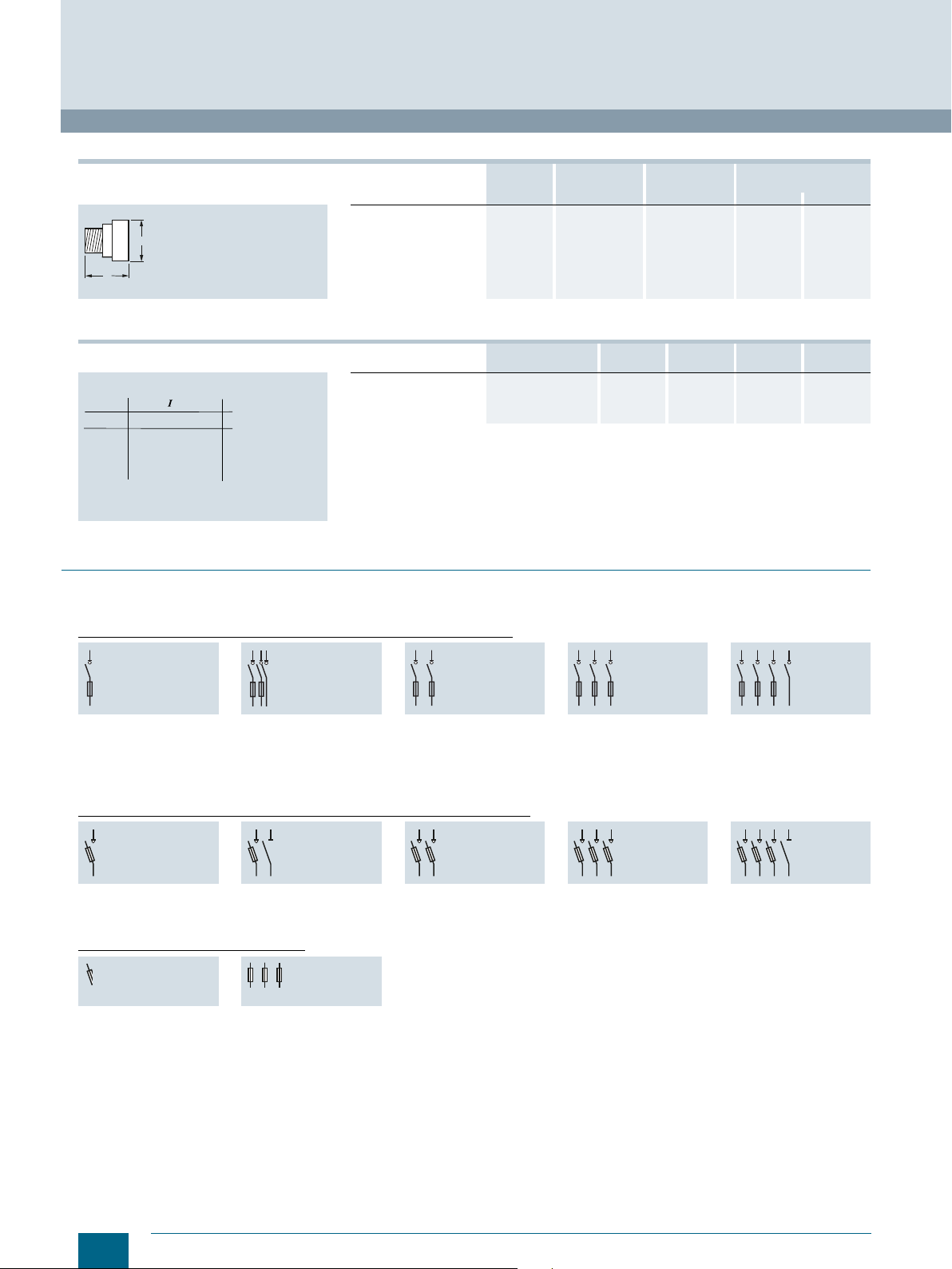
Circuit diagrams
Graphical symbols
5SG71.3 MINIZED D02 switch disconnectors, with draw-out technology
N
1
1
2
2
N
5SG7113 5SG7153 5SG7123 5SG7133
1P 1P+N 2P 3P 3P+N
5
21436
5SG7133-8BA25
5SG7133-8BA35
5SG7133-8BA50
5SG76 MINIZED D01 fuse switch disconnectors, with draw-out technology
123
4
5SG7610 5SG7650 5SG7620 5SG7630 5SG7660
1P 1P+N 2P 3P 3P+N
12345
6
NEOZED fuse bases/fuses in general
5SG1 5SG5
1P 3P
21436
5SG7163
5
N
N
12
Siemens · 10/2015
Page 15
■
p
[A]
[s]
I201_10887
46810
1
24
6810
2
24681032
4
6
10
-2
2
4
6
2
4
6
10
0
2
4
6
10
1
10
-1
2
4
6
2
4
6
10
3
2
4
6
10
4
10
2
2
4
2 A
4 A
6 A
10 A
13 A
16 A
20 A
25 A
32 A
35 A
50 A
40 A
63 A
80 A
100 A
vs
1 0
1
2
64 1 0
2
8
2
64 8 2 64
4
6
1 0
2
4
6
1 0
c
e f f
[ A ]
[ A ]
I 2 _ 1 0 8 8 8
2
4
6
1 0
2
2 4
2
3
4
1 0
3
8
1 0
4
6 8
1 0
5
2 4
1
2
4 A
2 A
1 0 0 A
8 0 A
6 3 A
5 0 A
4 0 A
3 5 A
3 2 A
2 5 A
2 0 A
1 6 A
1 3 A
1 0 A
6 A
2 6 1 01 0 4
0
2
64 1 0
1
8 2 64 1 028
3
8 2 6 1 0448
1 0
2
4
6
1 0
2
4
6
1 0
2
4
6
1 0
2
4
6
1 0
2
4
6
1 0
2
4
6
1 0
I 2 _ 1 0 8 8 9
0
1
2
3
4
5
6
e f f
[ A ]
2
s
[ A s ]
2
6
4
1 00s
1 0
- 1
s 1 0
- 2
s
1 0
- 3
s
1 0
- 4
s
8 0 A
6 3 A
5 0 A
4 0 A
3 5 A
2 5 A
2 0 A
1 6 A
1 3 A
1 0 A
6 A
4 A
2 A
3 2 A
1 0 0 A
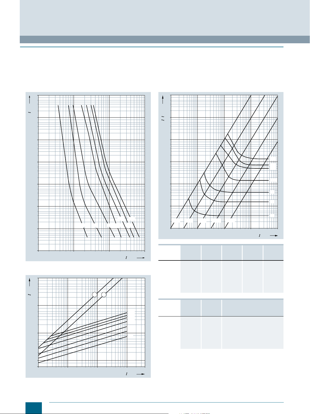
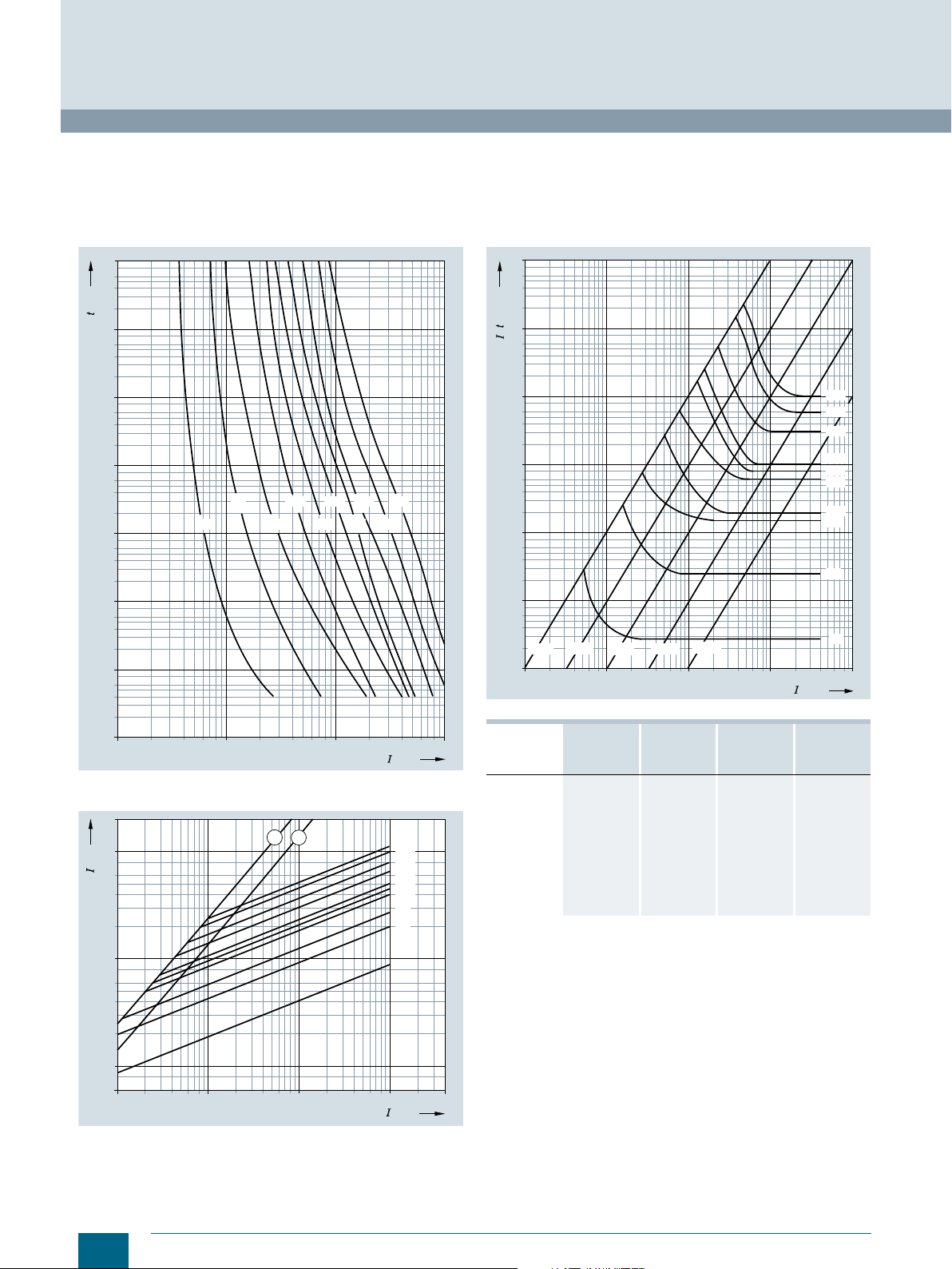
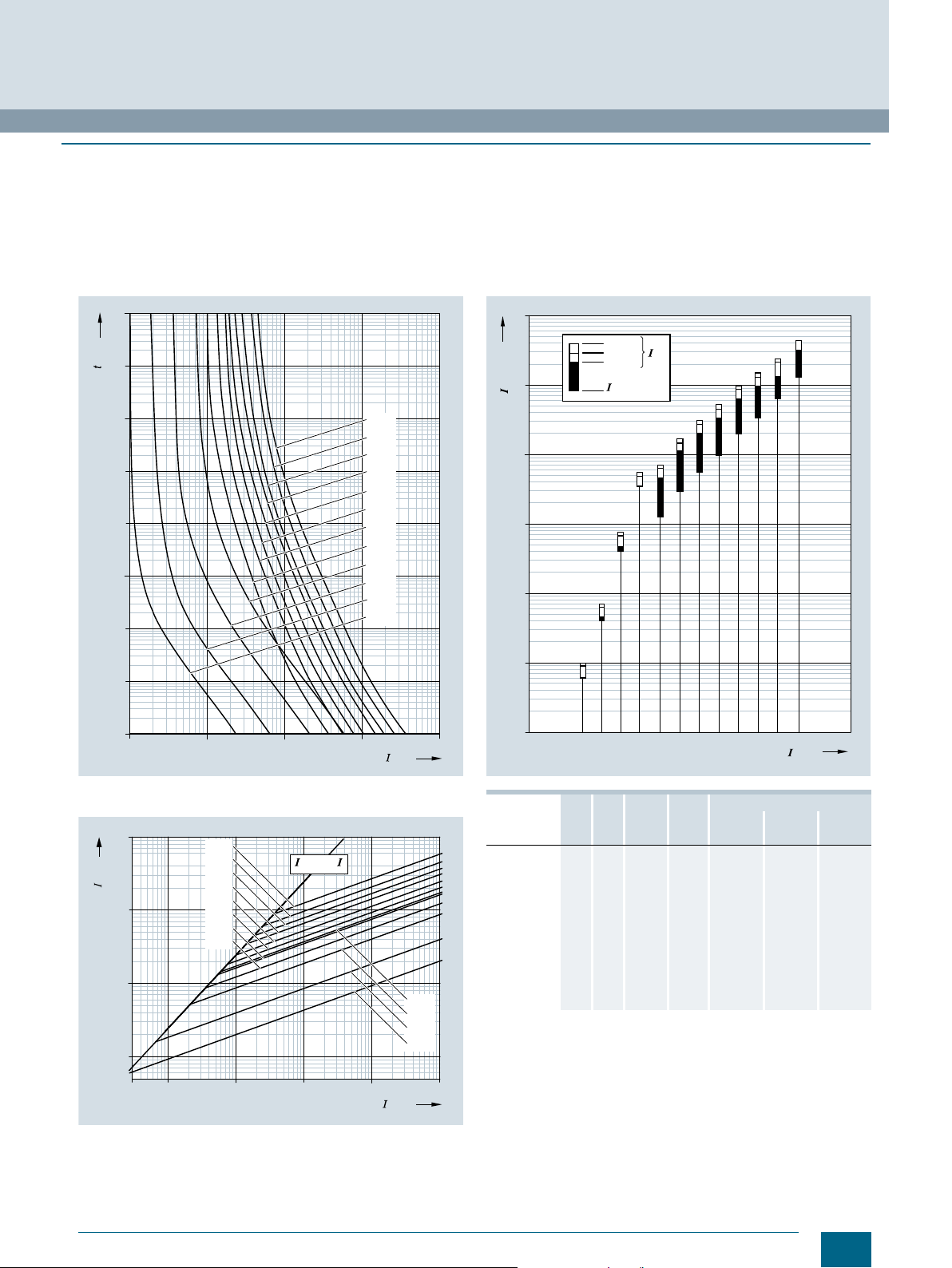
Characteristic curves
Series 5SE2
Sizes: D01, D02, D03
Operational class: gG
Rated voltage: 400 V AC/250 V DC
Rated current: 2 ... 100 A
Time/current characteristics diagram
© Siemens AG 2016
Fuse Systems
NEOZED Fuse Systems
NEOZED fuse links
Melting I2t values diagram
Current limiting diagram
Peak short-circuit current with largest DC component
$
% Peak short-circuit current without DC component
Ta bl e see page 14.
Siemens · 10/2015
13
Page 16

Fuse Systems
NEOZED Fuse Systems
NEOZED fuse links
Series 5SE2
Sizes: D01, D02, D03
Operational class: gG
Rated voltage: 400 V AC/250 V DC
Rated current: 2 ... 100 A
Typ e I
5SE2302
5SE2304
5SE2306
5SE2310
5SE2013-2A
5SE2316
5SE2320
5SE2325
5SE2332
5SE2335
5SE2340
5SE2350
5SE2363
5SE2280
5SE2300
n
A W K A2s A2s A2s A2s
2 1.6 19 1.2 1.4 2.9 3.9
4 1.3 14 12.5 13.6 22 30
6 1.7 19 46.7 48 58 75
10 1.3 16 120 136 220 280
13 2.0 23 220 244 290 370
16 2.1 24 375 410 675 890
20 2.4 26 740 810 1250 1650
25 3.2 33 1210 1300 1900 2600
32 3.6 34 2560 2800 4300 5500
35 3.8 36 3060 3500 5100 6500
40 4.0 37 4320 4800 7900 9500
50 4.2 38 6750 7400 10500 13000
63 5.3 45 10000 10900 16000 20500
80 5.3 43 13000 15400 25000 34500
100 6.4 47 22100 30000 46000 60000
P
v
© Siemens AG 2016
I2t
1ms 4ms 230 V AC 400 V AC
s
I2t
a
(t < 4ms)
14
Siemens · 10/2015
Page 17
■
Overview
The DIAZED fuse system is one of the oldest fuse systems in
the world. It was developed by Siemens as far back as 1906.
It is still the standard fuse system in many countries to this day.
It is particularly widely used in the harsh environments of industrial applications.
The series is available with rated voltages from 500 V to 750 V.
All DIAZED bases must be fed from the bottom to ensure an
insulated threaded ring when the fuse link is being removed.
Reliable contact of the fuse links is only ensured when used
together with DIAZED screw adapters.
The terminals of the DIAZED bases are available in different versions and designs to support the various installation methods.
The high-performing EZR bus-mounting system for screw fixing
is an outstanding feature. The busbars, which are particularly
suited for bus-mounting bases, have a load capacity of up to
150 A with lateral infeed.
DIAZED stands for Dia
system mit Ed
isongewinde (diametral two-step fuse system with
metral gestuftes zweiteiliges Sicherungs-
Edison screw).
© Siemens AG 2016
■
Benefits
1
2
3
4
5 9
6 10
7 11
8
Fuse Systems
DIAZED fuse systems
1
2
5
6
7
11
DIAZED cap for fuse bases
DIAZED collar for fuse bases
DIAZED fuse bases
DIAZED cover for fuse bases
DIAZED screw adapter
DIAZED fuse link
DIAZED screw cap
DIAZED fuse base (with touch protection BGV A3)
3
4
9
10
i201_18300
8
DIII fuse bases with terminal version BS
• Outgoing feeders (top), saddle terminal S
• Incoming feeders (bottom), clamp-type terminal B
DIII fuse bases with terminal version BB
• Outgoing feeders (top), clamp-type terminal B
• Incoming feeders (bottom), clamp-type terminal B
NDZ fuse bases with terminal version KK
• Outgoing feeders (top), screw head contact K
• Incoming feeders (bottom), screw head contact K
DIII fuse bases with terminal version SS
• Outgoing feeders (top), saddle terminal S
• Incoming feeders (bottom), saddle terminal S
Siemens · 10/2015
15
Page 18
© Siemens AG 2016
Fuse Systems
DIAZED fuse systems
■
Technical specifications
5SA, 5SB, 5SC, 5SD
Standards
Operational class Acc. to IEC 60269;
Characteristic Acc. to DIN VDE 0635
Rated voltage U
Rated current I
Rated breaking capacity kA AC
Overvoltage category
Mounting position
Non-interchangeability
Degree of protection Acc. to IEC 60529
Resistance to climate °C Up to 45, at 95 % rel. humidity
Ambient temperature °C
1)
Degree of protection IP20 is tested according to regulations using a
straight test finger (from the front), with the device mounted and equipped
with a cover, housing or some other enclosure.
n
n
DIN VDE 0636
V AC 500, 690, 750
V DC
A 2...100
kA DC
IEC 60269-3; DIN VDE 0635; DIN VDE 0636-3; CEE 16
gG
Slow and quick
500, 600, 750
50, 40 at E16
8, 1.6 at E16
III
II (DIAZED fuse bases made of molded plastic for use at 690 V AC / 600 V DC)
Any, preferably vertical
Using screw adapter or adapter sleeves
IP20, with connected conductors
-5 to +40, humidity 90 % at 20
1)
Terminal version
B K S R
Size
Conductor cross-sections
• Rigid, min. mm
• Rigid, max. mm
• Flexible, with end sleeve mm
Tightening torque
• Screw M4 Nm 1.2 --
• Screw M5 Nm
• Screw M6 Nm
• Screw M8 Nm
DII DIII NDz DII DIII DIII DIV DII DIII
2
1.5 2.5 1.0 1.5 2.5 2.5 10 1.5 1.5
2
10 25 6 10 25 25 50 35 35
2
10 25 6 10 25 25 50 35 35
2.0 --
2.5 3.0
3.5 --
16
Siemens · 10/2015
Page 19
49
I201_06251a
13,2
d
I201_06247
d
49
22,5
49
I201_06248
d
28
34,5
57
d
I201_06682
70
I201_06329a
ød
ø28
© Siemens AG 2016
■
Dimensional drawings
DIAZED fuse links
5SA1, 5SA2 Size/thread TNDz/E16, NDz/E16
Rated current in A 2 4 6 10 16 20 25
Dimension d
5SB1, 5SB2 Size/thread DII/E27
Rated current in A 2 4 6 10 16 20 25
Dimension d
5SB3, 5SB4 Size/thread DIII/E33
Rated current in A 32 35 50 63
Dimension d
6 6 6 8 10 12 14
6 6 6 8 10 12 14
16 16 18 20
Fuse Systems
DIAZED fuse systems
5SC1, 5SC2 Size/thread DIV/R1¼"
Rated current in A 80 100
Dimension d
5SD6, 5SD8 Size/thread DIII/E33
Rated current in A 2 4 6 10 16 20 25 35 50 63
Dimension d
5 7
6 6 6 8 10 12 14 16 18 20
Siemens · 10/2015
17
Page 20
Fuse Systems
I201_06242
a
b
h
Øi
c
g
d
e
80
max.113
12
5
105
50
65
M6
I2_06443a
I201_11344
a
b
43,6
6
80
DIAZED fuse systems
DIAZED fuse bases made of ceramic
5SF1
5SF4230
© Siemens AG 2016
Version
Typ e a b c d e g h i
NDz/25 A
5SF1012 KK 29 49 44.6 55 75 32 49 --
DII/25 A
5SF1005 BB 38.4 41 46.6 53 83 34 63 --
5SF1024
DIII/63 A
5SF1205 BS 45.5 46 47 54 83 43 78 --
5SF1215
5SF1224
DIV/100 A
5SF1401 Flat terminal 68 68 -- 79 110 65 116 6.5
Connection
type
Dimensions
BB 38.4 41 46.6 53 83 34 63 4.3
SS 45.5 46 47 54 83 43 78 -BS 45.5 46 47 54 83 43 78 4.3
DIAZED fuse bases made of molded plastic
5SF1, 5SF5 Typ e Dimensions
5SF1060
5SF1260
5SF5068
5SF5268
a b
40 -50 --
-- 120
-- 150
18
Siemens · 10/2015
Page 21
41,5
45
18
11
14
max.83
31
16
27
max.38,5
30
20,5
31
5
I2_06444a
34
max.49
3722
5,3
34
51,5
55
18
11
14
max.83
31
I2_06445a
16
a
I201_06257
b
I201_13741a
b
a
I201_06242
a
b
h
Øi
c
g
d
e
© Siemens AG 2016
Fuse Systems
DIAZED fuse systems
DIAZED EZR bus-mounting bases
5SF6005 5SF6205
DIAZED screw caps/cover rings made of molded plastic/ceramic
Screw caps Cover rings Screw caps Cover rings
5SH1 5SH3 Size/thread
NDz/E16
DII/E27 5SH1221 42 33 5SH3401 17.5 39.5
DIII/E33 5SH1231 42 40 5SH3411 17.5 49.5
Typ e Dimensions Typ e Dimensions
a b a b
5SH1112 36 24
5SH112 45.5 34 5SH332 17.5 41.5
5SH122 43 39
5SH113 45.5 43 5SH334 19 51.5
5SH123 47 45
5SH1161 48 48
5SH1170 68 43
DIAZED caps made of molded plastic
5SH2 Size/thread Ty pe Dimensions
NDz/E16 5SH201 33 68 51.7 75
DII/E27
DIII/E33
5SH202 43 74.7 53.6 83
5SH222 51 90.5 53.6 83
a
max
b
max
c
max
d
max
Siemens · 10/2015
19
Page 22
Fuse Systems
210
0
10
-3
2
4
6
10
-2
6410
1
82 64
10
2
824
2
4
6
10
-1
2
4
6
10
0
2
4
6
10
1
2
4
6
10
2
2
4
6
10
3
2
4
6
10
4
I2_06069c
6
10
3
8
2 A
vs
[A]
[s]
4 A 6 A 10 A 20 A
16 A 25 A
ef
ef
10
2
2
6410
3
8
2
4
6
2
4
6
10
I2_07032b
5
2 A
c
[A]
[A]
10
2
6
10
3
2
4
6
10
4
2
6410
4
8
2
6410
5
8
2
4
4 A
6 A
10 A
16 A
20 A
25 A
1
2
261010 4
0
2
6410
1
82 6410
2
8
3
82 610448
10
2
4
6
10
2
4
6
10
2
4
6
10
2
4
6
10
2
4
6
10
2
4
6
10
I2_07545c
0
1
2
3
4
5
6
25 A
20 A
16 A
2 A
[A]
2
s
[A s]
2
100s
10-1s
10-2s
10-3s
10-4s
4 A
6 A
10 A
ef
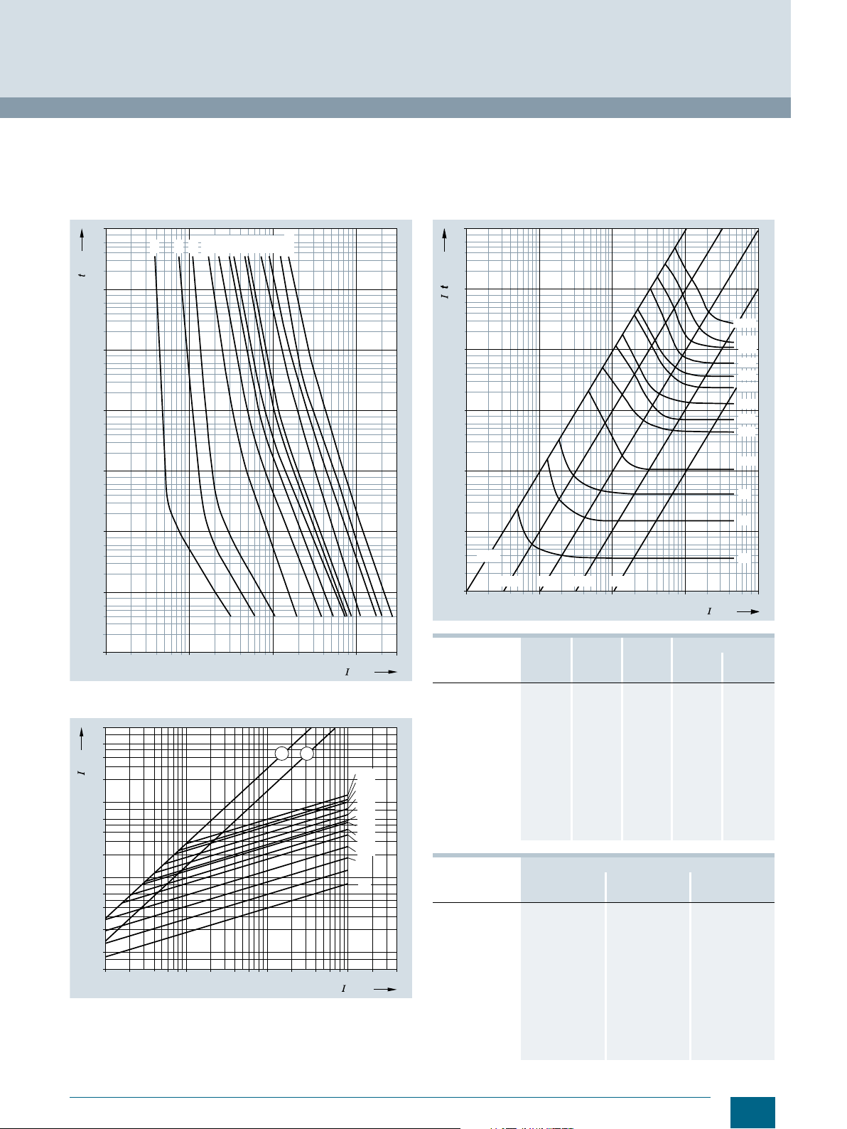
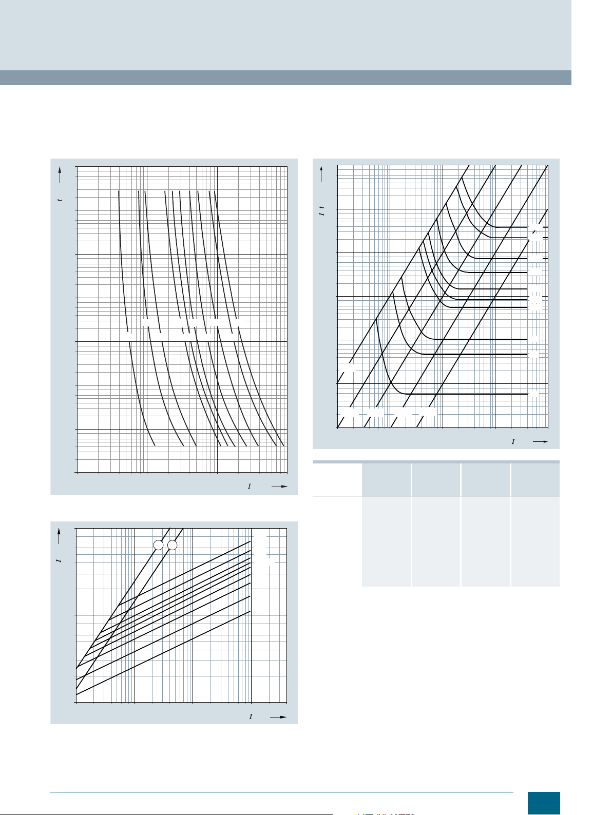
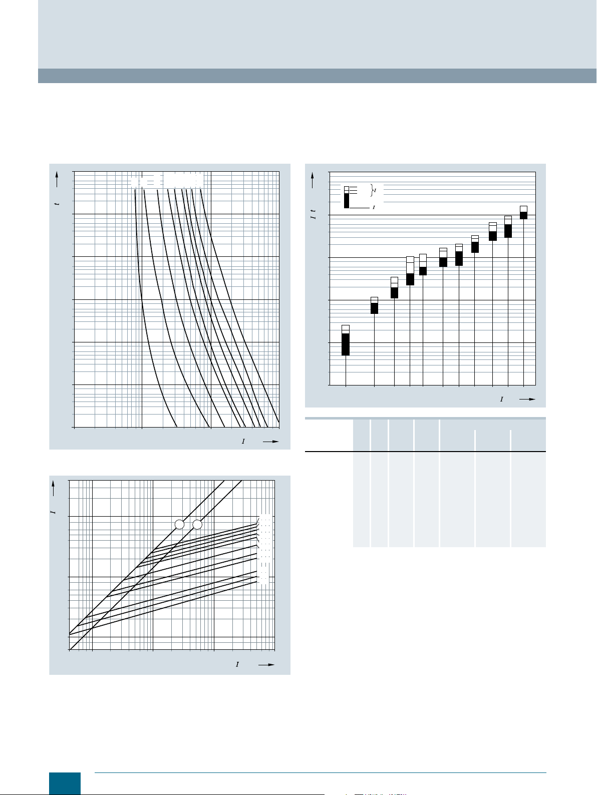
DIAZED fuse systems
■
Characteristic curves
Series 5SA2
Size: E16
Characteristics: Slow
Rated voltage: 500 V AC/500 V DC
Rated current: 2 ... 25 A
Time/current characteristics diagram
© Siemens AG 2016
Melting I2t values diagram
Current limiting diagram
$
Peak short-circuit current with largest DC component
% Peak short-circuit current without DC component
20
Siemens · 10/2015
Typ e I
A W K A2s A2s
5SA211
5SA221
5SA231
5SA251
5SA261
5SA271
5SA281
10 1.4 17 200 190
16 2.4 30 290 550
20 2.6 36 470 1990
25 3.4 34 1 000 2090
Typ e I2t
230 V AC 320 V AC 500 V AC
A2s A2s A2s
5SA211
5SA221
5SA231
5SA251
5SA261
5SA271
5SA281
1200 1350 1620
2400 2600 3450
n
2 0.85 15 1.2 2.3
4 1.3 17 8.5 13
6 1.9 14 40 80
a
22 26 34
66 76 100
240 270 340
890 950 1 090
P
v
6.6 7.8 0.7
I2t
1ms 4ms
s
Page 23
Series 5SB2, 5SB4, 5SC2
210
0
10
-3
2
4
6
10
-2
6410
1
82 64
10
2
824
2
4
6
10
-1
2
4
6
10
0
2
4
6
10
1
2
4
6
10
2
2
4
6
10
3
2
4
6
10
4
6
10
3
8
vs
[A]
[s]
2
I2_07551a
2 A
4 A
6 A
10 A
16 A
20 A
25 A
32 A
35 A
50 A
63 A
80 A
100 A
ef
10
2
2
6410
3
8
2
4
6
2
4
6
10
I2_06055b
5
2 A
c
[A]
[A]
10
2
6
10
3
2
4
6
10
4
2
6410
4
8
2
6410
5
8
2
4
4 A
6 A
10 A
16 A
20 A
25 A
32 A
50 A
63 A
80 A
100 A
1
2
35 A
ef
Size: DII, DIII, DIV
Operational class: gG
Rated voltage: 500 V AC/500 V DC
Rated current: 2 ... 100 A
Time/current characteristics diagram
© Siemens AG 2016
Melting I2t values diagram
6
10
6
4
2
2
[A s]
s
5
10
2
6
4
2
4
10
6
4
2
3
10
6
4
2
2
10
6
4
2
1
10
6
4
2
0
10
0
100s
2
10-1s
10-2s
1
6410
82 6410
10-3s
Fuse Systems
DIAZED fuse systems
10-4s
2
261010 4
8
82 610448
I2_07552a
100 A
80 A
63 A
50 A
35 A
32 A
25 A
20 A
16 A
10 A
6 A
4 A
2 A
3
[A]
ef
Typ e I
Current limiting diagram
$ Peak short-circuit current with largest DC component
% Peak short-circuit current without DC component
5SB211
5SB221
5SB231
5SB251
5SB261
5SB271
5SB281
5SB4010
5SB411
5SB421
5SB431
5SC211
5SC221
Typ e I2t
5SB211
5SB221
5SB231
5SB251
5SB261
5SB271
5SB281
5SB4010
5SB411
5SB421
5SB431
5SC211
5SC221
n
A W K A2s A2s
10 1.6 20 120 140
16 2.4 23 500 580
20 2.6 26 750 1100
25 3.4 38 1600 2000
32 3.6 23 2300 2500
35 3.7 25 3450 3000
50 5.7 41 6500 5200
63 6.9 48 11000 12 000
80 7.5 33 14600 16 400
100 8.8 46 28600 30 000
230 V AC 320 V AC 500 V AC
A2s A2s A2s
1200 1450 1 620
2400 3150 3 450
3450 4150 4 850
5200 6200 7 200
9750 12350 14500
16500 22200 26500
23000 28500 32500
44000 56000 65000
P
v
2 2.6 15 3.7 3.9
4 2.0 13 15 16
6 2.2 14 42 45
a
6.6 8.8 10.7
22 28 34
66 85 100
240 300 340
890 1 060 1090
I2t
s
1ms 4ms
Siemens · 10/2015
21
Page 24
ef
10
2
2
6410
3
8
2
4
6
I2_07101a
2 A
c
[A]
[A]
10
2
6410
4
8
2
6410
5
8
2
4
4 A
6 A
10 A
16 A
20 A
25 A
2
10
3
6
2
4
10
4
6
2
63 A
50 A
35 A
1
2
261010 4
0
2
6410
1
82 6410
2
8
3
82 610448
10
2
4
6
10
2
4
6
10
2
4
6
10
2
4
6
10
2
4
6
10
2
4
6
10
I2_06425b
0
1
2
3
4
5
6
2 A
[A]
2
s
[A s]
2
100s
10-1s
10-2s
10-3s
10-4s
25 A
20 A
16 A
4 A
6 A
10 A
35 A
50 A
63 A
ef
© Siemens AG 2016
Fuse Systems
DIAZED fuse systems
Series 5SD8
Size: DIII
Operational class: gG
Rated voltage: 690 V AC/600 V DC
Rated current: 2 ... 63 A
Time/current characteristics diagram
4
10
6
4
[s]
vs
2
3
10
6
4
2
2
10
6
4
2
1
10
6
4
2
0
10
6
4
2
-1
10
6
4
2
-2
10
6
4
2
-3
10
0
210
4 A 10 A 20 A 30 A 63 A
2 A 6 A 16 A 25 A 50 A
1
6410
82 64
2
10
824
6
8
[A]
ef
Current limiting diagram
$
Peak short-circuit current with largest DC component
% Peak short-circuit current without DC component
22
Siemens · 10/2015
Melting I2t values diagram
I2_06412c
Typ e I
3
10
5SD8002
5SD8004
5SD8006
5SD8010
5SD8016
5SD8020
5SD8025
5SD8035
5SD8050
5SD8063
n
P
v
I2t
s
I2t
a
4ms 242 V AC
A W A2s A2s
2 1 4.4 7
4 1.2 40 62
6 1.6 88 140
10 1.4 240 380
16 1.8 380 600
20 2 750 1 200
25 2.3 2000 3 200
35 3.1 3300 5 100
50 4.6 7000 11 000
63 5.5 9500 15 000
Page 25
21 0
0
1 0
- 3
2
4
6
1 0
- 2
64 1 018 2 64
1 0
2
8 2 4
2
4
6
1 0
- 1
2
4
6
1 0
0
2
4
6
1 0
1
2
4
6
1 0
2
2
4
6
1 0
3
2
4
6
1 0
4
I 2 _ 0 6 0 4 8 a
6
1 0
3
8
v s
e f f
[ A ]
[ s ]
2 A 6 A 5 0 A2 5 A1 6 A
4 A 1 0 A 2 0 A 3 0 A 6 3 A
10
2
2
6410
3
8
2
4
I2_06411a
2 A
c
[A]
[A]
10
2
6410
4
8
2
6410
5
8
2
4
4 A
6 A
10 A
16 A
20/25 A
2
10
3
6
2
4
10
4
6
63 A
50 A
35 A
1
2
ef
261010 4
0
2
6410
1
82 6410
2
8
3
82 610448
10
2
4
6
10
2
4
6
10
2
4
6
10
2
4
6
10
2
4
6
10
2
4
6
10
I2_06077b
-1
0
1
2
3
4
5
[A]
2
s
[A s]
2
6 A
2 A
4 A
10 A
16 A
20 A
25 A
35 A
50 A
63 A
10-1s
10-2s
10-3s
10-4s
100s
ef
© Siemens AG 2016
Series 5SD6
Size: DIII
Operational class: Quick (railway network protection)
Rated voltage: 750 V AC/750 V DC
Rated current: 2 ... 63 A
Time/current characteristics diagram
Fuse Systems
DIAZED fuse systems
Melting I2t values diagram
Typ e I
Current limiting diagram
Peak short-circuit current with largest DC component
$
% Peak short-circuit current without DC component
5SD601
5SD602
5SD603
5SD604
5SD605
5SD606
5SD607
5SD608
5SD610
5SD611
n
A W A2s A2s
2 2.8 0.7 2
4 4 4.5 13
6 4.8 10 29
10 4.8 50 135
16 5.9 78 220
20 6.3 125 380
25 8.3 265 800
35 13 550 1600
50 16.5 1800 5 500
63 18 3100 9 600
P
v
I2t
s
I2t
a
4ms 500 V AC
Siemens · 10/2015
23
Page 26
Fuse Systems
Cylindrical Fuse Systems
Cylindrical fuse links and cylindrical fuse holders
■
Overview
Cylindrical fuses are standard in Europe. There are a range of
different cylindrical fuse links and holders that comply with the
standards IEC 60269-1, -2 and -3, and which are suitable for use
in industrial applications. In South West Europe they are also
approved for use in residential buildings.
The cylindrical fuse holders are also approved according to
UL 512. The cylindrical fuse holders are tested and approved as
fuse disconnectors according to the switching device standard
IEC 60947-3. They are not suitable for switching loads.
Cylindrical fuse holders can be supplied with or without signal
detectors. In the case of devices with signal detector, a small
electronic device with LED is located behind an inspection
window in the plug-in module. If the inserted fuse link is tripped,
this is indicated by the LED flashing.
The switching state of the fuse holder can be signaled over a
laterally retrofitted auxiliary switch, which enables the integration
of the fuses in the automation process.
■
Technical specifications
Size mm × mm
Standards
Operational class
Rated voltages U
Rated current I
Rated breaking capacity
• 500 V versions kA AC
• 400 V versions kA AC
Mounting position
n
n
VAC 400 400 or 500
A 2...20 0.5 ... 32 4...50 8...100 0.5 ... 32 2...50 10 ... 100
© Siemens AG 2016
■
Benefits
• Devices with pole number 1P+N are available in a single
modular width. This reduces the footprint by 50 %
• The sliding catch for type ranges 8 x 32 mm and 10 x 38 mm
enables the removal of individual devices from the assembly
• Space for a spare fuse in the plug-in module enables the
fast replacement of fuses. This saves time and money and
increases system availability
• A flashing LED signals that a fuse link has been tripped.
This enables fast detection during runtime
Cylindrical fuse links
3NW63.. 3NW60.. 3NW61.. 3NW62.. 3NW80.. 3NW81.. 3NW82..
8×32 10 × 38 14 × 51 22 × 58 10 × 38 14 × 51 22 × 58
IEC 60269-1, -2, -3; NF C 60-200; NF C 63-210, -211; NBN C 63269-2, CEI 32-4, -12
gG aM
-- 120 100
20 120 120
Any, preferably vertical
20
120 100
20
Cylindrical fuse holders
3NW73.. 3NW70.. 3NW71.. 3NW72..
Size mm × mm
Standards
Approvals Acc. to UL
Rated voltage U
Rated current I
Rated breaking capacity kA
Breaking capacity
• Utilization category AC-20B (switching without load), DC-20B
No-voltage changing
of fuse links
Sealable
when installed
Mounting position
Degree of protection Acc. to IEC 60529
Terminals with touch protection
according to BGV A3 at incoming
and outgoing feeder
Ambient temperature °C -5 to +40, humidity 90 % at +20
Conductor cross-sections
• Rigid mm
•Stranded mm
• Finely stranded, with end sleeve mm
• AWG (American Wire Gauge) AWG
Tightening torque Nm
1)
Degree of protection IP20 is tested according to regulations using a
straight test finger (from the front), with the device mounted and equipped
with a cover, housing or some other enclosure.
2)
Max. cross-section 10 mm2 with K28 crimper from Klauke.
n
n
Acc. to CSA
Acc. to UL/CSA V AC
VAC 400 690
AAC 20 32 50 100
2
2
2
8×32 10 × 38 14 × 51 22 × 58
IEC 60269-1, -2, -3; NF C 60-200, NF C 63-210, -211; NBN C 63269-2-1; CEI 32-4, -12;
UL 4248-1
-- U U --
-- s s --
400 600
20 100
Ye s
Ye s
Any, preferably vertical
IP20, with connected conductors
Ye s
0.5 ... 10 2.5 ... 10 4...10
0.5 ... 10 2.5 ... 25 4...50
2)
0.5 ... 10
-- 10 ... 20 6...10 --
1.2 2.0 2.5
1)
2.5 ... 16 4...35
24
Siemens · 10/2015
Page 27
31,5
8,5
I2_06702c
58
22,2
I2_06704c
I201_12124
18 18 36 54 54 44
64
45
81
7
2
55
43
90
45
27
54
81 108
I201_07853b
7
70
70
43
45
7
117
I201_07869c
144
108
72
36
48,5
5
45
90
9
I201_10891
49,8
© Siemens AG 2016
Cylindrical Fuse Systems
Cylindrical fuse links and cylindrical fuse holders
■
Dimensional drawings
I2_06703c
38
Size
8 × 32 mm 10 × 38 mm 14 × 51 mm 22 × 58 mm
3NW70, 3NW73
1P 1P + N 2P 3P 3P+N
10,3
I2_06701c
14,3
51
Fuse Systems
3NW71
1P 1P+N/2P 3P 3P+N
3NW72
1P 1P+N/2P 3P 3P+N
Auxiliary switches
3NW7901
3NW7902
I201_15459
45
83
4469
64
3NW7903
Siemens · 10/2015
25
Page 28
Fuse Systems
2
1
22 14
13/21
22
12
21
11
Cylindrical Fuse Systems
Cylindrical fuse links and cylindrical fuse holders
■
Circuit diagrams
Graphical symbols
21N
© Siemens AG 2016
214
21436
2
N
1P 1P+N 2P 3P 3P+N
3
5
Auxiliary switches
3NW7901
3NW7902
3NW7903
NN56341
26
Siemens · 10/2015
Page 29
■
2
4
6
2
4
6
2
4
6
2
4
6
2
4
6
2
4
6
2
4
6
2
4
6
2 4 6 8 2 4 6 8 2 4 6 8 2 4 6 8 10
1
10
2
10
3
10
-4
10
-3
10
-2
10
-1
10
0
10
1
10
2
10
3
10
4
10
4
32 A
25 A
20 A
16 A
12 A
10 A
8 A
6 A
4 A
2 A
1 A
0,5 A
[A]
p
[s]
vs
Prospective short-circuit current
Virtual pre-arcing time
I201_19158
Characteristic curves
3NW60 series
Size: 10 × 38 mm
Operational class: gG
Rated voltage: 500 V AC (0.5 ... 25 A),
400 V AC (32 A)
Rated current: 2 ... 32 A
Time/current characteristics diagram
© Siemens AG 2016
Melting I2t values diagram
10
s]
2
t [A
2
10
10
10
10
10
10
Fuse Systems
Cylindrical Fuse Systems
Cylindrical fuse links and cylindrical fuse holders
4
6
4
2
3
6
4
2
2
6
4
2
1
6
4
2
0
6
4
2
-1
6
4
2
-2
500 V
400 V
230 V
0,512
²t
s
²t
a
681012
4
162025 32
n
[A]
I201_19160a
Current limiting diagram
$
% Peak short-circuit current without DC component
4
10
6
4
[A]
c
2
3
10
6
4
2
Peak current
2
10
6
4
2
1
10
5
36 246 246 246 246
32 A
25 A
20 A
= 2,3
m
p
16 A
12 A
10 A
8 A
6 A
1
10
2
10
Prospective short-circuit current
3
10
10
Peak short-circuit current with largest DC component
Typ e InPv I2tsI2t
a
1ms 230 V AC 400 V AC 500 V AC
A W K A2s A2s A2s A2s
0.5 0.07 On req. 0.06 0.06 0.09 0.10
1 0.45 On req. 0.50 0.45 0.63 0.7
2 0.50 On req. 4 4.80 6.80 7.50
4 0.85 On req. 34 35.70 49.50 55
6 0.95 On req. 12.5 45.50 63 70
8 1.15 On req. 29 10 153 170
10 1.30 On req. 56 201 279 310
12 1.40 On req. 99 344 477 530
16 1.90 On req. 199 630 873 970
20 2.40 On req. 333 975 1350 1500
25 2.70 On req. 619 1560 2160 2400
32 2.80 On req. 1331 3250 4500 --
4 A
I201_19159
3NW6000-1
3NW6011-1
3NW6002-1
3NW6004-1
3NW6001-1
3NW6008-1
3NW6003-1
3NW6006-1
3NW6005-1
3NW6007-1
3NW6010-1
3NW6012-1
2 A
1 A
0,5 A
4
p
5
10
[A]
Siemens · 10/2015
27
Page 30
Fuse Systems
210
0
10
-2
2
4
6
10
-1
6410
1
82 64
10
2
824
2
4
6
10
0
2
4
6
10
1
2
4
6
10
2
2
4
6
10
3
2
4
6
10
4
I2_06603b
6
10
3
8
vs
[A]
[s]
4 A
6 A
10 A
16 A
20 A
25 A
32 A
40 A
50 A
ef
10
2
c
[A]
[A]
10
I201_06560c
2
468 2 10
3
4
6
8
2
10
4
468
210
5
46
8
2
4
6
6
10
3
2
4
2
4
6
10
4
1
2
4 A
6 A
8 A
10 A
12 A
16 A
20 A
25 A
32 A
40 A
50 A
rms
Cylindrical Fuse Systems
Cylindrical fuse links and cylindrical fuse holders
3NW61series
Size: 14 × 51 mm
Operational class: gG
Rated voltage: 500 V AC (4 ... 40 A),
400 V AC (50 A)
Rated current: 4 ... 50 A
Time/current characteristics diagram
© Siemens AG 2016
Melting I2t values diagram
10
6
4
2
2
[A s]
2
10
6
4
2
10
6
4
2
10
6
4
2
10
6
4
2
10
5
500 A
2
400 A
t
a
230 A
2
t
4
3
2
1
0
4
s
6
10 401650
8 12
20 25 32
[A]
n
I2_06599c
Current limiting diagram
Peak short-circuit current with largest DC component
$
% Peak short-circuit current without DC component
28
Siemens · 10/2015
Typ e InPv I2tsI2t
1ms 230 V AC 400 V AC 500 V AC
A W K A2s A2s A2s A2s
3NW6104-1
3NW6101-1
3NW6108-1
3NW6103-1
3NW6106-1
3NW6105-1
3NW6107-1
3NW6110-1
3NW6112-1
3NW6117-1
3NW6120-1
4 1.9 19 5 16 20 26
6 2.5 25 48 85 100 120
8 2.4 18 110 200 250 350
10 0.8 12 230 420 750 1050
12 1.0 16 390 600 800 1200
16 1.6 27 600 1000 1 400 1700
20 2.3 32.5 670 1400 1800 2100
25 2.2 31.5 1300 2300 2800 3200
32 3.2 39.5 2500 4100 5500 6500
40 4.5 48 3600 6100 8 000 9200
50 4.8 55 8000 12 200 16000 --
a
Page 31

3NW62 series
210
1
10
-2
2
4
6
10
-1
6410
2
82 64
10
3
824
2
4
6
10
0
2
4
6
10
1
2
4
6
10
2
2
4
6
10
3
2
4
6
10
4
I2_06604b
6
10
4
8
vs
[A]
[s]
16 A
20 A
25 A
32 A
40 A
50 A
63 A
80 A
100 A
12 A
10 A
8 A
ef
1 0
2
2
64 1 08
1 0
2
4
6
c
e f f
[ A ]
[ A ]
1 0
2
3
2
64 1 08
4
2
64 1 08
5
2
4
I 2 _ 0 6 5 5 8 b
4
1 0
6
2 0 A
1 6 A
2 5 A
3 2 A
2
4
2
3
4
4 0 A
5 0 A
6 3 A
8 0 A
1 0 0 A
1
2
1 2 A
1 0 A
8 A
10
2
4
6
10
2
4
6
10
2
4
6
10
2
4
6
10
I2_06600c
0
1
2
3
4
n
[A]
2
[A s]
2
t
500 A
400 A
230 A
2
a
t
2
s
2
4
6
10
5
16
8032100
40 50 63
20 25
12108
Size: 22 × 58 mm
Operational class: gG
Rated voltage: 500 V AC (8 ... 80 A),
400 V AC (100 A)
Rated current: 8 ... 100 A
Time/current characteristics diagram
© Siemens AG 2016
Fuse Systems
Cylindrical Fuse Systems
Cylindrical fuse links and cylindrical fuse holders
Melting I2t values diagram
Typ e InPv I2tsI2t
a
1ms 230 V AC 400 V AC 500 V AC
A W K A2s A2s A2s A2s
3NW6208-1
Current limiting diagram
Peak short-circuit current with largest DC component
$
% Peak short-circuit current without DC component
3NW6203-1
3NW6206-1
3NW6205-1
3NW6207-1
3NW6210-1
3NW6212-1
3NW6217-1
3NW6220-1
3NW6222-1
3NW6224-1
3NW6230-1
8 2.5 15 110 200 170 350
10 0.9 10.5 230 420 760 1050
12 1.1 12 390 600 800 1200
16 1.6 14.5 600 1000 1400 1700
20 2.4 22.5 670 1200 1800 2200
25 2.7 24 1300 2100 2 800 3300
32 3.2 28 2450 4400 6 100 7200
40 4.9 35 3600 6200 8 000 10 000
50 5.9 46 6800 11400 16 200 20600
63 6.8 48 12 500 18800 24 000 30 000
80 7.5 48 24 700 30500 43 000 52 500
100 8.4 55 46000 64700 80 000 --
Siemens · 10/2015
29
Page 32

Fuse Systems
210
0
10
-2
2
4
6
10
-1
6410
1
82 64
10
2
824
2
4
6
10
0
2
4
6
10
1
2
4
6
10
2
2
4
6
10
3
2
4
6
10
4
I2_06605b
6
10
3
8
vs
[A]
[s]
4 A 10 A 20 A
2 A 6 A 16 A
ef
10
2
2
64108
10
4
6
2
4
6
2
c
[A]
[A]
10
3
2
3
2
64108
4
2
64108
5
2
4
I2_06559b
4
10
4
6
1
2
2 A
4 A
10 A
16 A
20 A
6 A
ef
2
10
2
4
6
10
2
4
6
10
2
4
6
10
2
4
6
10
I2_06601c
0
1
2
3
4
n
[A]
2
[A s]
2
4 6 10 16 20
t
400 A
230 A
2
a
t
2
s
Cylindrical Fuse Systems
Cylindrical fuse links and cylindrical fuse holders
3NW630.-1 series
Size: 8 × 32 mm
Operational class: gG
Rated voltage: 400 V AC
Rated current: 2 ... 20 A
Time/current characteristics diagram
© Siemens AG 2016
Melting I2t values diagram
Typ e I
n
P
v
I2t
I2t
s
a
1ms 400 V AC
A W K A2s A2s
3NW6302-1
3NW6304-1
3NW6301-1
3NW6303-1
3NW6305-1
Current limiting diagram
Peak short-circuit current with largest DC component
$
% Peak short-circuit current without DC component
30
Siemens · 10/2015
3NW6307-1
2 2 27 1.6 6
4 1.5 19 5 21
6 1.5 20.5 48 85
10 0.7 15 230 530
16 1.1 29 600 1 400
20 1.7 34.5 790 1 800
Page 33

2
10
-3
2
4
6
10
-2
6410
1
864
10
2
824
2
4
6
10
-1
2
4
6
10
0
2
4
6
10
1
2
4
6
10
2
2
4
6
10
3
I2_06567b
6
10
3
8
vs
[A]
[s]
16 A
20 A
25 A
32 A
40 A
50 A
63 A
80 A
100 A
224
0,5 A
1 A
2 A
4 A
12 A
10 A
8 A
6 A
ef
ef
10
2
6
c
[A]
[A]
10
I2_06566b
2
468 2 10
3
46
8
2
10
4
4682 10
5
468 2
2
4
6
10
3
2
4
6
10
4
2
1
2
0,5 A
100 A
80 A
63 A
50 A
40 A
32 A
25 A
20 A
16 A
12 A
10 A
8 A
6 A
4 A
2 A
1 A
10
2
4
6
10
2
4
6
10
2
4
6
10
2
4
6
10
0
1
2
3
4
n
[A]
2
[A s]
2
1 100
2
4
6
10
5
2
I2_06995b
2
500 A
400 A
t
2
s
468101216
20 25 32 40 50 63 80
© Siemens AG 2016
3NW8 series
Size: 10 × 38 mm, 14 × 51 mm, 22 × 58 mm
Operational class: aM
Rated voltage: 500 V AC,
400 V AC (3NW8120-1, 3NW8230-1)
Rated current: 0.5 ... 100 A
Time/current characteristics diagram
Fuse Systems
Cylindrical Fuse Systems
Cylindrical fuse links and cylindrical fuse holders
Melting I2t values diagram
Current limiting diagram
$ Peak short-circuit current with largest DC component
% Peak short-circuit current without DC component
Typ e Size BK I
3NW8000-1
3NW8011-1
3NW8002-1
3NW8004-1
3NW8001-1
3NW8008-1
3NW8003-1
3NW8006-1
3NW8005-1
3NW8007-1
3NW8010-1
3NW8012-1
3NW8102-1
3NW8104-1
3NW8101-1
3NW8108-1
3NW8103-1
3NW8106-1
3NW8105-1
3NW8107-1
3NW8110-1
3NW8112-1
3NW8117-1
3NW8120-1
3NW8208-1
3NW8203-1
3NW8206-1
3NW8205-1
3NW8207-1
3NW8210-1
3NW8212-1
3NW8217-1
3NW8220-1
3NW8222-1
3NW8224-1
3NW8230-1
mm A V W
10 x 38 aM 0.5 500 0.1
14 x 51 2 690 1
22 x 58 8 690 No info.
n
1 0.1
2 0.1
4 0.3
6 0.4
8 0.6
10 0.6
12 0.8
165 0.9
20 1.1
25 400 1.2
32 1.8
4 0.3
6 0.3
8 0.5
10 0.6
12 0.6
16 1
20 1
25 1.3
32 1.9
40 2
50 500 3.7
10 No info.
12 No info.
16 0.9
20 1.1
25 1.4
32 2
40 2.5
50 2.6
63 4.1
80 4.9
100 500 5.6
U
n
Siemens · 10/2015
P
v
31
Page 34

Fuse Systems
Cylindrical Fuse Systems
Fuse holders in size 10 x 38 mm and Class CC
■
Overview
A key feature of our three-pole fuse holders is their ultra compact
design. With a width of only 45 mm, they are ideal for use with
fused motor starter combinations. Because the contactor and
the fuse holder have the same 45 mm width, they are easy to
mount on top of one another. The strong current-limiting fuses
ensure a type 2 protection level (coordination according to
IEC 60947-4, no damage protection) for the contactor.
The UL version has an SCCR value of 200 kA. The accessories
are generally UL-certified.
Customers can mount an auxiliary switch which signals the
switching state or prevents the fuse holder from switching off
under load by interrupting the contactor control, thus increasing
safety for the operator and process. Busbars and a matching
three-phase feeder terminal complete the product range.
© Siemens AG 2016
■
Benefits
• Compact design, especially for motor starter combinations
• For IEC fuses of size 10 x 38 mm up to 32 A and Class CC
UL fuses up to 30 A
• Meets the requirements of UL 508 with regard to clearances
• UL-approved microswitches, busbars and adapters for
60 mm busbar systems
• Optical signal detector for fast fault locating
Compact cylindrical fuse holder Class CC with signal detector and
mounted auxiliary switch
Installation configuration of a cylindrical fuse holder and a SIRIUS
contactor on busbar device adapter for the 60 mm busbar system
32
Siemens · 10/2015
Page 35

© Siemens AG 2016
Fuse Systems
Cylindrical Fuse Systems
Fuse holders in size 10 x 38 mm and Class CC
■
Technical specifications
Cylindrical fuse holders Fuse holders
3NW70..-1 3NW75..-1HG
Size mm × mm
Standards
Approvals
• Acc. to UL U, UL File Number E171267 u, UL File Number E171267
• Acc. to CSA
Rated voltage U
Rated current I
Rated short-circuit strength kA
Breaking capacity
• Utilization category AC-20B (switching without load) --
Rated impulse withstand voltage kV
Overvoltage category
Pollution degree
Max. power dissipation of the fuse link W
No-voltage changing of fuse links °C
Sealable when installed
Lockable with padlock
Mounting position
Current direction
Degree of protection Acc. to IEC 60529
Terminals with touch protection acc. to BGVA3
at incoming and outgoing feeder
Ambient temperature °C
Conductor cross-sections
• Finely stranded, with end sleeve mm
• AWG cables (American Wire Gauge) AWG
Tightening torque Nm
• Terminal screws
1)
Degree of protection IP20 is tested according to regulations using a
straight test finger (from the front), with the device mounted and equipped
with a cover, housing or some other enclosure.
n
n
VAC 690 600
AAC 32 30
lb.in
10 × 38 Class CC
IEC 60269; UL4248-1; CSA UL4248-1; CSA
s s
120 (at 500 V)
80 (at 690 V)
6
III
2
3
-5 to +40, humidity 90 % at +20
Ye s
Ye s
Any, preferably vertical
Any
IP20, with connected conductors
Ye s
-5 to +40, humidity 90 % at +20
2
1...4
18 ... 10
1.5
13
PZ2
1)
200
Auxiliary switches
3NW7903-1
Standards
Approvals
Utilization category
Rated voltage U
Rated current I
For cylindrical fuse holders
Pin spacing mm
Standards
Approvals
Busbar material
Partition material
Lamp wire resistance/1.5 mm
Insulation coordination
Rated operating voltage U
• Acc. to UL V AC -- 600
• Acc. to IEC V AC
Maximum busbar current I
• Acc. to UL A -- 65
• Acc. to IEC A
n
n
2
n
n
VAC 250 -- -- -- 24 120 240 240
VDC
A 5 2 0.5 0.25 4 3 1.5 5
°C 960
IEC 60947
U, s, UL 508, UL File Number E334003
AC-12 DC-13 AC-15 Acc. to UL
-- 24 120 240 -- -- -- --
Busbars
5ST260.
3NW70. .-1 3NW75. .-1HG
15
EN 609741 (VDE 0660-100), IEC 60947-1:2004, UL 508, CSA 22.2
u, UL 4248-1, UL File Number E337131
E-Cu 58 F25
PA6 6- V0
Overvoltage category III, degree of pollution 2
690 --
80 --
Siemens · 10/2015
33
Page 36

© Siemens AG 2016
Fuse Systems
Cylindrical Fuse Systems
Fuse holders in size 10 x 38 mm and Class CC
Terminals
5ST2600
For cylindrical fuse holders
Pin spacing mm
Standards
Approvals
Enclosure/cover material
Lamp wire resistance/1 mm
Temperature resistance PA66-V0, HDT B ISO 179,
UL 94-V0/1.5
Insulation coordination
Maximum operating voltage U
• Acc. to UL V AC -- 600
• Acc. to IEC V AC
Maximum electrical load I
• Acc. to UL A -- 65
• Acc. to IEC A
Rated current I
Conductor cross-sections
• Solid/stranded mm
• Finely stranded, with end sleeve mm
Tightening torque of clamping screw Nm
n
max
2
max
°C 960
°C
A 63
3NW70. .-1 3NW75. .-1HG
15
IEC 60999:2000, UL 508
u, UL 4248-1, UL File Number E337131
PA6 6- V0
200
Overvoltage category III, degree of pollution 2
690 --
80 --
2
2.5 ... 35
2
2.5 ... 25
2.5 ... 3.5
34
Siemens · 10/2015
Page 37

■
I202_01414
I202_01412
I202_01447
6
54321
22
14
13
21
Dimensional drawings
3NW703. -1
3NW753. -1HG
© Siemens AG 2016
Fuse Systems
Cylindrical Fuse Systems
Fuse holders in size 10 x 38 mm and Class CC
5ST260. 5ST2600
■
Circuit diagrams
Circuit diagrams
3NW703. -1
3NW753. -1HG
3NW7903-1
I202_01413
Siemens · 10/2015
35
Page 38

© Siemens AG 2016
Fuse Systems
Class CC fuse systems
■
Overview
Class CC fuses are used for "branch circuit protection".
The enclosed fuse holders are designed and tested to comply
with the US National Electrical Code NEC 210.20(A). This means
that when subject to continuous operation, only 80 % of the rated
current is permissible as operational current.
An operational current of 100 % of the rated current (30 A) is only
permissible short-time.
The devices are prepared for the inscription labels of the
ALPHA FIX terminal blocks 8WH8120-7AA15 and
8WH8120-7XA05.
There are three different series:
• Characteristic: slow 3NW1...-0HG
For the protection of control transformers, reactors, inductances. Significantly slower than the minimum requirements
specified by UL for Class CC Fuses of 12 s at 2 × I
■
Technical specifications
Standards
Approvals
Rated voltage U
Rated current I
Rated conditional short-circuit current kA
Breaking capacity
• Utilization category AC-20B (switching without load)
Max. power dissipation of the fuse link
• With cable, 6 mm
• With cable, 10 mm
Rated impulse withstand voltage kV
Overvoltage category
Pollution degree
No-voltage changing of fuse links
Sealable when installed
Mounting position
Current direction
Degree of protection acc. to IEC 60529 IP20
Terminals with touch protection acc. to BGVA3
at incoming and outgoing feeder
Ambient temperature °C
Conductor cross-sections
• Solid and stranded mm
• AWG conductor cross-section, solid and stranded AWG
Tightening torque Nm
n
n
2
2
.
n
Class CC fuse holders
3NW75.3-0HG
UL 4248-1; CSA C22.2
UL 4248-1; UL File Number E171267; CSA C22.2
V AC 600
A 30
W 3
W 4.3
2
200
6
II
2
Ye s
Ye s
Any
Any
Ye s
45
1.5 ... 16
15 ... 5
2.5 (22 lb.in)
• Characteristic: quick 3NW2...-0HG
For a wide range of applications, for the protection of lighting
installations, heating, control systems.
• Characteristic: slow, current-limiting 3NW3...-0HG
Slow for overloads and quick for short circuits. High current
limitation for the protection of motor circuits.
Note:
For class CC compact fuse holders for motor starter combinations, see page 32.
■
Benefits
• For switchgear assemblies and machine manufacturers
who export their systems to the USA or Canada
• Easier export due to UL and CSA approvals for typical
applications
• Modern design with touch protection to BGV A3 ensures
safe installation.
Standards
Approvals
Characteristic
Rated voltage VAC
VDC
Rated breaking capacity kA AC
36
Siemens · 10/2015
Class CC fuse links
3NW1...-0HG 3NW2...-0HG 3NW3...-0HG
UL 248-4; CSA C22.2
UL 248-4; UL File Number E258218; CSA C22.2
Slow Quick Slow, current limiting
600
--
200
600
--
600
150 (3 .... 15 A)
300 (< 3 A, > 15 A)
Page 39

■
38,1
Ø
10,3
Dimensional drawings
3NW1. . .-0HG
3NW2. . .-0HG
3NW3. . .-0HG
© Siemens AG 2016
3NW75. 3-0HG
Fuse Systems
Class CC fuse systems
I201_13727
45
81
7
543618
37
49
58
Siemens · 10/2015
37
Page 40

Fuse Systems
Prospective short-circuit current
Virtual melting time
I202_02185
0,6 A
0,8 A
1 A
1,5 A
2 A
3 A
4 A
5 A
6 A
7,5 A
2,5 A
210
0
64868 210
1
64810242
p
[
A]
10
2
4
6
8
-1
10
2
4
6
8
0
10
2
4
6
8
1
10
t
vs
[s]
2
8
6
10
2
4
2
[s]
p
[A]
210
0
6481012648102264810
3
1 A
2 A
3 A
5 A
8 A
10 A
15 A
20 A
30 A
-2
10
2
4
6
8
-1
10
2
4
6
8
0
10
2
4
6
8
1
10
2
2
10
2
4
6
8
3
10
4
6
8
I201_12162a
Prospective short-circuit current
Virtual melting time
t
vmt
210
0
648 210
1
648 210
2
6810
3
4
p
[A]
-2
10
2
4
6
8
-1
10
2
4
6
8
0
10
2
4
6
8
1
10
2
2
10
3
10
2
4
6
8
4
6
8
1 A
3 A
4 A
6 A
8 A
10 A
12 A
15 A
20 A
25 A
30 A
[s]
I201_12163a
Prospective short-circuit current
Virtual melting time
t
vmt
Class CC fuse systems
■
Characteristic curves
3NW1...-0HG series
Time/current characteristics diagram
© Siemens AG 2016
3NW2...-0HG series
Time/current characteristics diagram
3NW1...-0HG series
Time/current characteristics diagram
3
10
8
6
[s]
t
vs
10
4
2
2
8
6
4
8 A
10 A
15 A
20 A
2
1
10
Virtual melting time
8
6
4
2
0
10
8
6
4
2
-1
10
8
6
4
2
-2
10
0
210
648 210
1
Prospective short-circuit current
38
Siemens · 10/2015
30 A
6648 8210
2
3NW3...-0HG series
Time/current characteristics diagram
I202_02186
3
10
4
[A]
p
Page 41

3NW3...-0HG series
210
1
64810226424810
3
p
[A]
1
10
2
4
6
8
2
10
2
3
10
2
4
4
6
8
c
[A]
I201_12164
30 A
25 A
20 A
15 A
2,8 A
1,25 A
Current limiting diagram
© Siemens AG 2016
Fuse Systems
Class CC fuse systems
Siemens · 10/2015
39
Page 42

Fuse Systems
Busbar systems
■
Overview
Busbars with pin-type connections can be used for NEOZED
safety switching devices and fuse bases. Busbars in 10 mm
and 16 mm2 versions are available.
■
Benefits
© Siemens AG 2016
Busbars with fork plugs are used for the most frequently used
2
NEOZED fuse bases made of ceramic.
• Clear and visible conductor connection that can be easily
checked when using the NEOZED D02 comfort base and
which facilitates cable entry
• Bus-mounting of NEOZED fuse bases made of ceramic on
3-phase busbar with fork plug, which can be cut to length
• Bus-mounting of NEOZED fuse bases made of molded plastic
on 3-phase busbar with fork plug, which can be cut to length
• Bus-mounting of MINIZED D01 fuse switch disconnectors on
3-phase busbar with fork plug, can be cut to length
• Clear and visible conductor connection that can be easily
checked when using MINIZED D02 switch disconnectors.
This facilitates cable entry and saves time
40
Siemens · 10/2015
• Bus-mounting of cylindrical fuse holders 8 × 32 mm and
10 × 38 mm with three-phase pin busbar that can be cut
to length
Page 43

© Siemens AG 2016
Fuse Systems
Busbar systems
• Bus-mounting of SITOR cylindrical fuse holders
10 mm x 38 mm with the same terminal connection
as Class CC fuse holders with 3-phase pin busbar
• Bus mounting with infeed through a connection terminal
directly on the fuse holder up to a conductor cross-section
of 25 mm²
that can be cut to length
■
Technical specifications
5ST, 5SH
Standards
Busbar material
Partition material
Rated operational voltage U
Rated current I
• Cross-section 10 mm
• Cross-section 16 mm
Rated impulse withstand voltage U
Test pulse voltage (1.2/50) kV
Rated conditional short-circuit current I
Resistance to climate
• Constant atmosphere Acc. to DIN 50015 23/83; 40/92; 55/20
• Humid heat Acc. to
Insulation coordination
• Overvoltage category III
• Pollution degree
Maximum busbar current I
• Infeed at the start of the busbar
- Cross-section 10 mm
- Cross-section 16 mm
• Infeed at the center of the busbar
- Cross-section 10 mm
- Cross-section 16 mm
n
2
2
2
2
2
2
c
per phase
S
imp
cc
IEC 60068-2-30
VAC 400
A 63
A 80
kV 4
kA 25
A 63
A 80
A 100
A 130
EN 60439-1 (VDE 0660-500): 2005-01
SF-Cu F 24
Plastic Cycoloy 3600,
heat-resistant above 90 °C,
flame-retardant,
self-extinguishing,
free of dioxins and halogens
6.2
28 cycles
2
Siemens · 10/2015
41
Page 44

S
I201_13755
© Siemens AG 2016
Fuse Systems
Busbar systems
5ST37. . - .HG busbars acc. to UL 508
5ST37. .-0HG 5ST37 . .-2HG 5ST3770-0HG 5ST3770-1HG
Standards
Approvals
Operational voltage
• Acc. to IEC V AC 690
• Acc. to UL 489 V AC
Rated conditional short-circuit current kA
• Dielectric strength kV/mm
• Surge strength kV
Rated current A
Maximum busbar current I
• Infeed at the start of the busbar A 80 100 -- --
• Infeed at the center of the busbar A
per phase
S
Insulation coordination
• Overvoltage category III
• Pollution degree
Busbar cross-section mm
Infeed
Conductor cross-sections AWG
mm
Terminals
• Terminal tightening torque Nm -- -- 5 3.5
lbs/in
UL 508, CSA C22.2 No. 14-M 95
UL 508 File No. E328403
CSA
600
10 (RMS symmetrical 600 V for three cycles)
25
> 9.5
-- -- 115
160 200 -- --
2
2
Cu 18 25 -- --
Any
-- -- 10 ... 1/0 14 ... 1
2
-- -- 6 ... 35 1.5 ... 50
-- -- 50 35
Infeed at the start of the busbar Infeed along the busbar or midpoint infeed
321
S1
The sum of the output current per branch must not be greater than the
busbar current I
S1,2
/phase.
1
S
2 3
S2
I201_13754a
42
Siemens · 10/2015
Page 45

■
3,5
13
1,5
I201_13674
1
15
18
1
L1 L2
I201_13748
15
18
L1 L2 L3
11
L1 L2 L3
1,5 1,5
I201_13749
I201_13750
13
3,5
15,1
I201_13426a
52
6
6
960
1030
13
2
97
6
6
6
872
970
13
3
I201_13427a
I201_13825
1,5
15
5
2
1,5
12
3
12
I201_13827
Dimensional drawings
5ST37
Pin spacing in MW (modular width; 1 MW = 18 mm)
Dimensions of side views in mm (approx.)
© Siemens AG 2016
Fuse Systems
Busbar systems
5ST3700
5ST3701
Single-phase Single-phase Two-phase
5ST3708
5ST3710
Three-phase Three-phase
5ST3703 5ST3704
5ST3705
5ST3714
5ST2
Fork spacing in MW (modular width; 1 MW = 18 mm)
Dimensions of side views in mm (approx.)
5ST2186
5ST2190
Single-phase Two-phase Three-phase
5ST2187
5ST2191
5ST2188
5ST2192
Busbars for DIAZED EZR fuse bases
5SH3500 5SH3501
5SH5
Fork spacing in MW (modular width; 1 MW = 18 mm), dimensions of side views in mm (approx.)
1,5
17
I201_13826
15
5SH5517 5SH5320 5SH5321 5SH5322
Siemens · 10/2015
43
Page 46

2
1
I202_02123
1,5
15
5
L2L1
1
1,5
21
23
L1 L2 L3
11
23
21
L1 L2 L3
1,5 1,5
I202_02122
1,5
2,5
I202_02104
1,5
15
5
23
21
1,5
L1 L2
2
I202_02105
23
21
L1 L2 L3
21,5 1,5
I202_02106
14
59,5
1
I202_02107
24
22 9,5
I202_02108
18,5
60
8
3
16
28,5
I202_02110
85,2
14 3,8
5,7
R 0,5
24
23,8
71,2
17,8
© Siemens AG 2016
Fuse Systems
Busbar systems
5ST37 . . - . HG busbars acc. to UL 508
5ST37
Pin spacing in MW (modular width; 1 MW = 18 mm)
Dimensions of side views in mm (approx.)
5ST3701-0HG 5ST3703-0HG 5ST3705-0HG
5ST3710-0HG 5ST3714-0HG 5ST3701-2HG
5ST3705-2HG 5ST3710-2HG
5ST3748-0HG 5ST3750-0HG
30
5ST3770-0HG 5ST3770-1HG
5ST36 touch protection covers
Pin spacing in MW (modular width; 1 MW = 18 mm)
Dimensions of side views in mm (approx.)
I202_02111
40
18
5ST3655-0HG
44
Siemens · 10/2015
Page 47

■
Overview
LV HRC fuse systems (NH type) are used for installation systems
in non-residential, commercial and industrial buildings as well as
in switchgear assemblies of power utilities. They therefore protect essential building parts and systems.
LV HRC fuse systems (NH type) are fuse systems designed for
operation by experts. There are no constructional requirements
for non-interchangeability of rated current and touch protection.
The components and auxiliary equipment are designed in such
a way as to ensure the safe replacement of LV HRC fuse systems
or isolation of systems.
LV HRC fuse links are available in the sizes 000, 00, 0, 1, 2, 3, 4
and 4a.
LV HRC components:
© Siemens AG 2016
Fuse Systems
3NA, 3ND LV HRC Fuse Systems
LV HRC fuse links
LV HRC fuse links are available in the following operational
classes:
• gG for cable and line protection
• aM for short-circuit protection of switching devices in motor
circuits
• gR or aR for protection of power semiconductors
• gS: The new gS operational class combines cable and line
protection with semiconductor protection
LV HRC fuse links of size 000 can also be used in LV HRC fuse
bases, LV HRC fuse switch disconnectors, LV HRC fuse strips as
well as LV HRC in-line fuse switch disconnectors of size 00.
The fuse links 300 A, 355 A and 425 A comply with the standard
but do not have the VDE mark.
5
4
2
1
10 11 12
15 16 17 18 19
3
6
7
13
LV HRC fuse base from the SR60 busbar system
1
LV HRC fuse base for busbar mounting
2
LV HRC fuse base, 3-pole
3
LV HRC fuse base, 1-pole
4
LV HRC contact covers
5
LV HRC fuse link
6
LV HRC signal detector
8
9
14
7
LV HRC partition
8
LV HRC protective cover
9
LV HRC fuse bases with swivel mechanisms,
- for screw fixing on mounting plate
10
- for screw fixing on busbar system
11
- for claw fixing on busbar
12
LV HRC protective cover for LV HRC fuse bases with
13
swivel mechanism
14
LV HRC swivel mechanism
15
LV HRC fuse base cover
16
LV HRC isolating blade with insulated grip lugs
17
LV HRC isolating blade with non-insulated grip lugs
I201_13743a
18
LV HRC fuse puller with sleeve
19
LV HRC fuse puller
Siemens · 10/2015
45
Page 48

© Siemens AG 2016
Fuse Systems
3NA, 3ND LV HRC Fuse Systems
LV HRC fuse links
■
Technical specifications
LV HRC fuse links
Operational class Operational
gG aM
3NA6...-4 3NA6... 3NA3... 3NA6...-6 3NA3...-6 3ND1
3NA6...-4KK 3NA6...-7 3NA3...-7 3NA7...-6 3ND2
3NA383.-8 3NA7...
Standards IEC 60269-1, -2; EN 60269-1; DIN VDE 0636
Approvals
Rated voltage U
• Sizes 000 and 00 V AC 400 500 500 690
• Sizes 1 and 2 V AC
•Size 3 VAC
• Sizes 4 and 4a (IEC design) V AC
Rated current I
Rated breaking capacity kA AC
Contact pins
Resistance to climate °C
1)
Manufacturer's confirmation for 690 V +10 % rated voltage available on
request.
n
n
DIN VDE 0636-2; CSA 22.2 No.106, File Number 016325_0_00 (CSA approval of fuses 500 V for 600 V)
VDC
-- 250 250 250 250 --
400 500 500 690
VDC
-- 440 440 440 440 --
-- -- 500 -- 690
VDC
-- -- 440 -- 440 --
-- -- 500 -- -- --
VDC
-- -- 440 -- -- --
A 10 ... 400 2...400 2 ... 1250 2...315 2...500 6...630
120
kA DC
-- 25 --
Non-corroding, silver-plated
-20 ... +50 at 95% relative humidity
3NA7...-7
class
1)
1)
690
690
1)
1)
1)
500
690
690
46
Siemens · 10/2015
Page 49

■
210
1
10
-3
2
4
6
10
-2
6410
2
82 64
10
3
824
2
4
6
10
-1
2
4
6
10
0
2
4
6
10
1
2
4
6
10
2
2
4
6
10
3
2
4
6
10
4
I2_06088a
6
10
4
8
6 A
10 A
16 A
20 A
25 A
80 A
100 A
125 A
160 A
32 A
35 A
40 A
63 A
50 A
vs
[A]
[s]
ef
ef
10
2
2
64108
10
2
4
6
160 A
100 A
2
4
6
3
40 A
32 A
20 A
10 A
125 A
50 A
35 A
25 A
16 A
6 A
c
[A]
[A]
10
4
2
3
2
64108
4
2
64108
5
2
4
80 A
63 A
I2_06062a
1
2
ef
261010 4
1
2
6410
2
82 6410
3
8
4
82 610458
10
2
4
6
10
2
4
6
10
2
4
6
10
2
4
6
10
2
4
6
10
2
4
6
10
I2_06081b
1
2
3
4
5
6
7
160 A
125 A
80 A
63 A
50 A
40 A
32 A
25 A
20 A
16 A
100 A
6 A
10A
35 A
100s
10-1s
10-2s
10-3s
10-4s
[A]
2
s
[A s]
2
Characteristic curves
3NA30 series
Size: 0
Operational class: gG
Rated voltage: 500 V AC/440 V DC
Rated current: 6 ... 160 A
Time/current characteristics diagram
© Siemens AG 2016
Fuse Systems
3NA, 3ND LV HRC Fuse Systems
LV HRC fuse links
Melting I2t values diagram
Current limiting diagram
$
Peak short-circuit current with largest DC component
% Peak short-circuit current without DC component
Typ e I
3NA3001
3NA3003
3NA3005
3NA3007
3NA3010
3NA3012
3NA3014
3NA3017
3NA3020
3NA3022
3NA3024
3NA3030
3NA3032
3NA3036
Typ e I2t
3NA3001
3NA3003
3NA3005
3NA3007
3NA3010
3NA3012
3NA3014
3NA3017
3NA3020
3NA3022
3NA3024
3NA3030
3NA3032
3NA3036
n
A W K A2s A2s
10 1 9 120 130
16 1.9 11 370 420
20 2.3 13 670 750
25 2.7 15 1200 1380
32 3 13 2200 2400
35 3 17 3000 3300
40 3.4 17 4000 4500
50 4.5 24 6000 6800
63 5.8 27 7700 9800
80 7 34 12000 16000
100 8.2 37 24000 30600
125 10.2 38 36000 50 000
160 13.5 44 58000 85 000
230 V AC 400 V AC 500 V AC
A2s A2s A2s
14200 19000 26500
23100 30700 43000
40800 56200 80000
70000 91300 130000
120000 158 000 223 000
P
v
I2t
s
1ms 4ms
6 1.5 6 46 50
a
80 110 150
180 265 370
580 750 1000
1000 1370 1900
1800 2340 3300
3400 4550 6400
4900 6750 9300
6100 8700 12100
9100 11 600 16 000
Siemens · 10/2015
47
Page 50

ef
261010 4
1
2
6410
2
82 6410
3
8
4
82 610458
10
2
4
6
10
2
4
6
10
2
4
6
10
2
4
6
10
2
4
6
10
2
4
6
10
I2_06082b
1
2
3
4
5
6
7
10-2s
100s
10-1s
10-3s
10-4s
160 A
125 A
80 A
63 A
50 A
40 A
35 A
25 A
20 A
16 A
100 A
200 A
224 A
250 A
[A]
2
s
[A s]
2
© Siemens AG 2016
Fuse Systems
3NA, 3ND LV HRC Fuse Systems
LV HRC fuse links
3NA31, 3NA61, 3NA71 series
Size: 1
Operational class: gG
Rated voltage: 500 V AC/440 V DC
Rated current: 16 ... 250 A
Time/current characteristics diagram
4
10
6
4
[s]
vs
2
3
10
6
4
2
2
10
6
4
2
1
10
6
4
2
0
10
6
4
2
-1
10
6
4
2
-2
10
6
4
2
-3
10
16 A
20 A
25 A
1
210
80 A
50 A
40 A
63 A
35 A
2
6410
82 64
100 A
125 A
160 A
200 A
224 A
250 A
3
10
824
6
8
[A]
ef
Current limiting diagram
4
[A]
2
c
4
10
1
6
4
2
3
10
6
4
2
10
2
Peak short-circuit current with largest DC component
$
% Peak short-circuit current without DC component
48
Siemens · 10/2015
64108
3
2
64108
4
2
2
250 A
224 A
200 A
160 A
125 A
100 A
80 A
63 A
50 A
40 A
35 A
25 A
20 A
16 A
5
64108
ef
[A]
2
Melting I2t values diagram
I2_06063c
Typ e InPv I2t
4
10
3NA3105, 3NA6105, 3NA7105
3NA3107, 3NA6107, 3NA7107
3NA3110, 3NA6110, 3NA7110
3NA3114, 3NA6114, 3NA7114
3NA3117, 3NA6117, 3NA7117
3NA3120, 3NA6120, 3NA7120
3NA3122, 3NA6122, 3NA7122
3NA3124, 3NA6124, 3NA7124
I2_06053b
3NA3130, 3NA6130, 3NA7130
3NA3132, 3NA6132, 3NA7132
3NA3136, 3NA6136, 3NA7136
3NA3140, 3NA6140, 3NA7140
3NA3142, 3NA6142, 3NA7142
3NA3144, 3NA6144, 3NA7144
Typ e I2t
3NA3105, 3NA6105, 3NA7105
3NA3107, 3NA6107, 3NA7107
3NA3110, 3NA6110, 3NA7110
3NA3114, 3NA6114, 3NA7114
3NA3117, 3NA6117, 3NA7117
4
3NA3120, 3NA6120, 3NA7120
3NA3122, 3NA6122, 3NA7122
3NA3124, 3NA6124, 3NA7124
3NA3130, 3NA6130, 3NA7130
3NA3132, 3NA6132, 3NA7132
3NA3136, 3NA6136, 3NA7136
3NA3140, 3NA6140, 3NA7140
3NA3142, 3NA6142, 3NA7142
3NA3144, 3NA6144, 3NA7144
s
1ms 4ms
A W K A2s A2s
16 2.1 8 370 420
20 2.4 10 670 750
25 2.8 11 1200 1380
35 3.2 16 3000 3300
40 3.6 16 4000 4500
50 4.6 20 6000 6800
63 6 21 7700 9800
80 7.5 29 12 000 16000
100 8.9 30 24 000 30600
125 10.7 31 36000 50 000
160 13.9 34 58000 85 000
200 15 36 115 000 135 000
224 16.1 37 145 000 170000
250 17.3 39 205 000 230000
a
230 V AC 400 V AC 500 V AC
A2s A2s A2s
580 750 1 000
1000 1370 1 900
1800 2340 3 300
4900 6750 9 300
6100 8700 12 100
9100 11600 16 000
14200 19000 26500
23100 30700 43000
40800 56200 80000
70000 91300 130 000
120000 158000 223000
218000 285000 400000
299000 392000 550000
420000 551000 780000
Page 51

rms
I201_06042b
10
2
2
64108
10
160 A
100 A
2
4
6
3
125 A
50 A
c
[A]
[A]
10
4
2
3
2
64108
4
2
64108
5
2
4
80 A
63 A
4
200 A
250 A
6
1
2
261010 4
2
2
6410
3
82 6410
4
8
5
82 610468
10
2
4
6
10
2
4
6
10
2
4
6
10
2
4
6
10
2
4
6
10
2
4
6
10
I201_06043c
2
3
4
5
6
7
8
100s
10-1s
10-2s
10-3s
10-4s
160 A
125 A
80 A
63 A
50 A
100 A
200 A
250 A
[A]
2
s
[A s]
2
rms
© Siemens AG 2016
Fuse Systems
3NA, 3ND LV HRC Fuse Systems
LV HRC fuse links
3NA31..-6, 3NA61..-6, 3NA71..-6 series
Size: 1
Operational class: gG
Rated voltage: 690 V AC
Rated current: 50 ... 200 A
Time/current characteristics diagram
4
10
6
4
[s]
vs
2
3
10
6
4
2
2
10
6
4
2
1
10
6
4
2
0
10
6
4
2
-1
10
6
4
2
-2
10
6
4
2
-3
10
1
210
2
6410
82 64
Current limiting diagram
Peak short-circuit current with largest DC component
$
% Peak short-circuit current without DC component
1)
/440 V DC
250 A
200 A
160 A
125 A
100 A
80 A
63 A
50 A
3
10
824
rms
Melting I2ts values diagram
I201_06044b
Typ e InPv I2t
4
10
6
8
[A]
3NA3120-6, 3NA6120-6, 3NA7120-6
3NA3122-6, 3NA6122-6, 3NA7122-6
3NA3124-6, 3NA6124-6, 3NA7124-6
3NA3130-6, 3NA6130-6, 3NA7130-6
3NA3132-6, 3NA6132-6, 3NA7132-6
3NA3136-6, 3NA6136-6, 3NA7136-6
3NA3140-6, 3NA6140-6, 3NA7140-6
Typ e I2t
A W K A2s A2s
50 6.7 21 440 7 400
63 7.6 22 7600 10100
80 6.7 22 13500 17000
100 8.7 28 21 200 30 500
125 10.5 29 36 000 50000
160 13.8 33 58 000 85000
200 16.6 35 132000 144000
a
230 V AC 400 V AC 690 V AC
A2s A2s A2s
3NA3120-6, 3NA6120-6, 3NA7120-6
3NA3122-6, 3NA6122-6, 3NA7122-6
3NA3124-6, 3NA6124-6, 3NA7124-6
3NA3130-6, 3NA6130-6, 3NA7130-6
3NA3132-6, 3NA6132-6, 3NA7132-6
3NA3136-6, 3NA6136-6, 3NA7136-6
3NA3140-6, 3NA6140-6, 3NA7140-6
1)
Manufacturer's confirmation for 690 V +10 % rated voltage available on
request.
9100 11 200 1900
13600 17 000 24 000
24300 32 000 55 000
42400 52 000 75 000
69500 82 200 130000
120000 155000 223000
211000 240000 360000
Siemens · 10/2015
s
1ms 4ms
49
Page 52

Fuse Systems
26410
2
8
10
-3
2
4
6
10
-2
6410
3
82 6410
4
824
2
4
6
10
-1
2
4
6
10
0
2
4
6
10
1
2
4
6
10
2
2
4
6
10
3
2
4
6
10
4
I2_06085a
50 A
63 A
80 A
100 A
35 A
vs
[A]
[s]
125 A
160 A
200 A
224 A
250 A
300/315 A
355 A
400 A
ef
10
2
2
64108
10
160 A
100 A
2
4
6
3
125 A
50 A
35 A
c
[A]
[A]
10
4
2
3
2
64108
4
2
64108
5
2
4
80 A
63 A
I2_06060a
4
200 A
224 A
250 A
6
300/315 A
355 A
400 A
1
2
ef
ef
261010 4
2
2
6410
3
82 6410
4
8
5
82 610468
10
2
4
6
10
2
4
6
10
2
4
6
10
2
4
6
10
2
4
6
10
2
4
6
10
I2_06079b
3
1
4
5
6
7
8
9
160 A
125 A
80 A
63 A
50 A
100 A
35 A
100s
10-1s
10-2s
10-3s
10-4s
200 A
224 A
250 A
300/315 A
355 A
400 A
[A]
2
s
[A s]
2
3NA, 3ND LV HRC Fuse Systems
LV HRC fuse links
3NA32, 3NA62, 3NA72 series
Size: 2
Operational class: gG
Rated voltage: 500 V AC/440 V DC
Rated current: 35 ... 400 A
Time/current characteristics diagram
© Siemens AG 2016
Melting I2t values diagram
Typ e InPv I2t
s
1ms 4ms
Current limiting diagram
$ Peak short-circuit current with largest DC component
% Peak short-circuit current without DC component
50
Siemens · 10/2015
3NA3214, 3NA6214, 3NA7214
3NA3220, 3NA6220, 3NA7220
3NA3222, 3NA6222, 3NA7222
3NA3224, 3NA6224, 3NA7224
3NA3230, 3NA6230, 3NA7230
3NA3232, 3NA6232, 3NA7232
3NA3236, 3NA6236, 3NA7236
3NA3240, 3NA6240, 3NA7240
3NA3242, 3NA6242, 3NA7242
3NA3244, 3NA6244, 3NA7244
3NA3250, 3NA6250
3NA3252, 3NA6252, 3NA7252
3NA3254, 3NA6254
3NA3260, 3NA6260, 3NA7260
Typ e I2t
3NA3214, 3NA6214, 3NA7214
3NA3220, 3NA6220, 3NA7220
3NA3222, 3NA6222, 3NA7222
3NA3224, 3NA6224, 3NA7224
3NA3230, 3NA6230, 3NA7230
3NA3232, 3NA6232, 3NA7232
3NA3236, 3NA6236, 3NA7236
3NA3240, 3NA6240, 3NA7240
3NA3242, 3NA6242, 3NA7242
3NA3244, 3NA6244, 3NA7244
3NA3250, 3NA6250
3NA3252, 3NA6252, 3NA7252
3NA3254, 3NA6254
3NA3260, 3NA6260, 3NA7260
A W K A2s A2s
35 3.2 12 3000 3300
50 4.7 16 6000 6800
63 5.9 16 7700 9800
80 6.8 21 12 000 16 000
100 7.4 22 24 000 30 600
125 9.8 27 36 000 50 000
160 12.6 34 58 000 85000
200 14.9 33 115000 135 000
224 15.4 31 145000 170 000
250 17.9 38 205000 230 000
300 19.4 34 361000 433 000
315 21.4 35 361000 433 000
355 26.0 49 441000 538 000
400 27.5 52 529000 676 000
a
230 V AC 400 V AC 500 V AC
A2s A2s A2s
4900 6750 9 300
9100 11 600 16 000
14200 19000 26500
23100 30700 43000
40800 56200 80000
70000 91300 130 000
120000 158 000 223 000
218000 285 000 400 000
299000 392 000 550 000
420000 551 000 780 000
670000 901 000 1275000
670000 901 000 1275000
800000 1060000 1500000
1155 000 1515000 2150000
Page 53

3NA32..-6, 3NA62..-6, 3NA72..-6 series
ef
210
2
10
-3
2
4
6
10
-2
6410
3
82 64
10
4
824
2
4
6
10
-1
2
4
6
10
0
2
4
6
10
1
2
4
6
10
2
2
4
6
10
3
2
4
6
10
4
I2_07539a
6
10
5
8
250 A
224 A
200 A
160 A
125 A
100 A
80 A
300/315 A
vs
[A]
[s]
1 0
2
2
64 1 08
1 0
2
4
6
1 6 0 A
1 0 0 A
2
4
6
4
1 2 5 A
c
e f f
[ A ]
[ A ]
1 0
5
1 0
3
3
2
64 1 08
4
2
64 1 08
5
2
4
8 0 A
I 2 _ 0 7 5 4 0 a
2 0 0 A
2 2 4 A
2 5 0 A
1
2
3 1 5 A
Size: 2
Operational class: gG
Rated voltage: 690 V AC
1)
/440 V DC
Rated current: 80 ... 315 A
Time/current characteristics diagram
© Siemens AG 2016
Melting I2t values diagram
9
10
6
4
2
2
[A s]
s
8
2
10
6
4
2
7
10
6
4
2
6
10
6
4
2
5
10
6
4
2
4
10
6
4
2
3
10
Fuse Systems
3NA, 3ND LV HRC Fuse Systems
LV HRC fuse links
I2_07541a
100s
10-1s
10-2s
10-3s
10-4s
300/315 A
250 A
240 A
200 A
160 A
125 A
100 A
80 A
2
2
3
6410
82 6410
8
4
261010 4
5
82 610468
[A]
ef
Typ e InPv I2t
s
1ms 4ms
Current limiting diagram
Peak short-circuit current with largest DC component
$
% Peak short-circuit current without DC component
3NA3224-6, 3NA6224-6, 3NA7224-6
3NA3230-6, 3NA6230-6, 3NA7230-6
3NA3232-6, 3NA6232-6, 3NA7232-6
3NA3236-6, 3NA6236-6, 3NA7236-6
3NA3240-6, 3NA6240-6, 3NA7240-6
3NA3242-6, 3NA6242-6, 3NA7242-6
3NA3244-6, 3NA6244-6, 3NA7244-6
3NA3250-6, 3NA6250-6, 3NA7250-6
3NA3252-6, 3NA6252-6, 3NA7252-6
Typ e I2t
3NA3224-6, 3NA6224-6, 3NA7224-6
3NA3230-6, 3NA6230-6, 3NA7230-6
3NA3232-6, 3NA6232-6, 3NA7232-6
3NA3236-6, 3NA6236-6, 3NA7236-6
3NA3240-6, 3NA6240-6, 3NA7240-6
3NA3242-6, 3NA6242-6, 3NA7242-6
3NA3244-6, 3NA6244-6, 3NA7244-6
3NA3250-6, 3NA6250-6, 3NA7250-6
3NA3252-6, 3NA6252-6, 3NA7252-6
1)
Manufacturer's confirmation for 690 V +10 % rated voltage available on
request.
A W K A2s A2s
80 6.6 22 13 500 17 000
100 8.5 26 21200 30 500
125 9.8 29 36000 50 000
160 13.3 31 58 000 85000
200 16.1 33 132 000 144000
224 19.9 38 125 000 162000
250 23 44 180000 215 000
300 25.6 38 300 000 380000
315 28.2 42 300 000 380000
a
230 V AC 400 V AC 690 V AC
A2s A2s A2s
24300 32 000 55 000
42400 52 000 75 000
69500 82 200 130000
120000 155000 223000
211000 240000 360000
300000 300000 450000
453000 350000 525000
480000 625000 940000
480000 625000 940000
Siemens · 10/2015
51
Page 54

Fuse Systems
3NA, 3ND LV HRC Fuse Systems
LV HRC fuse links
3NA33 series
Size: 3
Operational class: gG
Rated voltage: 500 V AC/440 V DC
Rated current: 200 ... 630 A
Time/current characteristics diagram
4
10
6
4
[s]
vs
2
3
10
6
4
2
2
10
6
4
630 A
500 A
425 A
400 A
355 A
300/315 A
250 A
224 A
200 A
© Siemens AG 2016
Melting I2t values diagram
9
10
6
4
2
I2_06051a
2
[A s]
s
8
10
2
6
4
2
7
10
6
4
2
6
10
6
4
2
5
10
6
4
2
4
10
6
4
2
3
10
100s
10-1s
2
2
3
6410
82 6410
8
4
261010 4
10-2s
10-3s
10-4s
630 A
500 A
425 A
400 A
355 A
300/315 A
250 A
224 A
200 A
5
82 610468
[A]
ef
I2_06070b
Current limiting diagram
5
10
1
2
64108
630 A
500 A
425 A
400 A
355 A
300/315 A
250 A
224 A
200 A
5
[A]
6
c
4
2
4
10
6
4
3
10
2
$
Peak short-circuit current with largest DC component
64108
4
2
% Peak short-circuit current without DC component
Typ e I
P
n
v
I2t
s
1ms 4ms
A W K A2s A2s
3NA3340
3NA3342
3NA3344
3NA3350
3NA3352
3NA3354
I2_06061a
3NA3360
3NA3362
3NA3365
3NA3372
Typ e I2t
200 14.9 32 115000 135 000
224 15.4 31 145000 170 000
250 17.9 36 205000 230 000
300 19.4 19 361000 433 000
315 21.4 22 361000 433 000
355 26.0 26 441000 538 000
400 27.5 28 529000 676 000
425 26.5 34 650000 970 000
500 36.5 41 785000 1270000
630 44.0 50 1900000 2700000
a
230 V AC 400 V AC 500 V AC
A2s A2s A2s
3NA3340
3NA3342
3NA3344
3NA3350
3NA3352
3NA3354
3NA3360
3NA3362
3NA3365
6
2
64108
[A]
ef
3NA3372
218000 285 000 400 000
299000 392 000 550 000
420000 551 000 780 000
670000 901 000 1 275000
670000 901 000 1 275000
800000 1 060 000 1 500 000
1155 000 1515 000 2150 000
1515 000 1856 000 2270 000
1915 000 2260 000 2700 000
3630 000 4340 000 5400 000
52
Siemens · 10/2015
Page 55

3NA33..-6 series
210
2
10
-3
2
4
6
10
-2
6410
3
82 64
10
4
824
2
4
6
10
-1
2
4
6
10
0
2
4
6
10
1
2
4
6
10
2
2
4
6
10
3
2
4
6
10
4
I2_07542a
6
10
5
8
425 A
400 A
355 A
315 A
250 A
500 A
vs
[A]
[s]
ef
ef
10
10
2
4
6
5
c
[A]
[A]
10
4
4
2
648 64108
5
2
4
I2_07543a
250 A
355 A
1
2
315 A
400 A
425 A
500 A
ef
261010 4
2
2
6410
3
82 6410
4
8
5
82 610468
10
2
4
6
10
2
4
6
10
2
4
6
10
2
4
6
10
2
4
6
10
2
4
6
10
I2_07544a
3
4
5
6
7
8
9
100s
10-1s
10-2s
10-3s
10-4s
355 A
315 A
250 A
400 A
500 A
[A]
2
s
[A s]
2
425 A
Size: 3
Operational class: gG
Rated voltage: 690 V AC
1)
Rated current: 250 ... 500 A
Time/current characteristics diagram
© Siemens AG 2016
Fuse Systems
3NA, 3ND LV HRC Fuse Systems
LV HRC fuse links
/440 V DC
Melting I2t values diagram
Typ e I
Current limiting diagram
$
Peak short-circuit current with largest DC component
% Peak short-circuit current without DC component
3NA3344-6
3NA3352-6
3NA3354-6
3NA3360-6
3NA3362-6
3NA3365-6
Typ e I2t
3NA3344-6
3NA3352-6
3NA3354-6
3NA3360-6
3NA3362-6
3NA3365-6
1)
Manufacturer's confirmation for 690 V +10 % rated voltage available on
request.
P
n
A W K A2s A2s
250 23 44 180 000 215 000
315 28.2 42 300 000 380 000
355 32.5 40 380 000 470 000
400 33.2 42 540 000 675 000
425 35.3 44 625 000 765 000
500 43.5 52 810 000 1 000000
a
230 V AC 400 V AC 690 V AC
A2s A2s A2s
453000 350 000 525 000
480000 625 000 940 000
585000 760 000 1 150000
847000 1 100000 1 650 000
925000 1 200000 1 800 000
1300 000 1700 000 2500 000
I2t
v
Siemens · 10/2015
s
1ms 4ms
53
Page 56

Fuse Systems
ef
vs
210
2
10
-3
2
4
6
10
-2
6410
3
82 64
10
4
824
2
4
6
10
-1
2
4
6
10
0
2
4
6
10
1
2
4
6
10
2
2
4
6
10
3
2
4
6
10
4
I2_07549a
6
10
5
8
1250 A
1000 A
800 A
630 A
[A]
[s]
3NA, 3ND LV HRC Fuse Systems
LV HRC fuse links
3NA34 series
Size: 4 (IEC design)
Operational class: gG
Rated voltage: 500 V AC/440 V DC
Rated current: 630 ... 1250 A
Time/current characteristics diagram
© Siemens AG 2016
Melting I2t values diagram
10
10
6
4
2
2
[A s]
s
9
2
10
6
4
2
8
10
6
4
2
7
10
6
4
2
6
10
6
4
2
5
10
6
4
2
4
10
I2_07556b
100s
10-1s
10-2s
10-3s
10-4s
1250 A
1000 A
800 A
630 A
2
2
3
6410
82 6410
8
4
261010 4
5
82 610468
[A]
ef
Typ e I
P
n
v
I2t
s
1ms 4ms
Current limiting diagram
6
[A]
4
c
2
5
10
6
4
2
4
10
3
10
2
Peak short-circuit current with largest DC component
$
64108
4
2
% Peak short-circuit current without DC component
54
Siemens · 10/2015
64108
1
2
1250 A
1000 A
800 A
630 A
5
2
46810
[A]
ef
3NA3472
3NA3475
3NA3480
3NA3482
Typ e I2t
I2_07550a
3NA3472
3NA3475
3NA3480
3NA3482
6
A W K A2s A2s
630 47 37 1900000 2 700000
800 59 43 3480000 5 620000
1000 74 56 7920000 10400000
1250 99 65 11 880 000 18200 000
a
230 V AC 400 V AC 500 V AC
A2s A2s A2s
3630 000 4340 000 5400 000
7210 000 8510 000 10400000
13600 000 16 200000 19000 000
23900 000 29 100000 34800 080
Page 57

3NA36 series
210
2
10
-3
2
4
6
10
-2
6410
3
82 64
10
4
824
2
4
6
10
-1
2
4
6
10
0
2
4
6
10
1
2
4
6
10
2
2
4
6
10
3
2
4
6
10
4
I2_06049a
6
10
5
8
1250 A
1000 A
800 A
630 A
500 A
vs
[A]
[s]
ef
Size: 4a
Operational class: gG
Rated voltage: 500 V AC/440 V DC
Rated current: 500 ... 1250 A
Time/current characteristics diagram
© Siemens AG 2016
Melting I2t values diagram
10
10
6
4
2
2
[A s]
s
9
10
2
6
4
2
10
6
4
2
10
6
4
2
6
10
6
4
2
10
6
4
2
4
10
Fuse Systems
3NA, 3ND LV HRC Fuse Systems
LV HRC fuse links
s
10-4s
1250 A
1000 A
800 A
630 A
500 A
I2_06073b
0
s
10
10-1s
10-2s
8
7
5
2
2
3
6410
82 6410
8
4
261010 4
82 610468
-3
10
5
[A]
ef
Typ e I
P
n
v
I2t
s
1ms 4ms
Current limiting diagram
6
4
[A]
c
2
5
10
6
4
1
2
1250 A
1000 A
800 A
630 A
500 A
3NA3665
3NA3672
3NA3675
3NA3680
3NA3682
Typ e I2t
I2_06057a
3NA3665
3NA3672
3NA3675
3NA3680
3NA3682
A W K A2s A2s
500 43 30 785000 1270000
630 47 37 1900000 2700000
800 59 43 3480000 5620000
1000 74 56 7920 000 10400 000
1250 99 65 11 880 000 18200 000
a
230 V AC 400 V AC 500 V AC
A2s A2s A2s
1915000 2260000 2700000
3630000 4340000 5400000
7210000 8510000 10400 000
13600 000 16 200000 19000 000
23900 000 29 100000 34800 000
2
4
10
3
10
2
Peak short-circuit current with largest DC component
$
64108
4
2
64108
5
% Peak short-circuit current without DC component
2
46810
[A]
ef
6
Siemens · 10/2015
55
Page 58

Fuse Systems
26410
1
8
10
-3
2
4
6
10
-2
6410
2
82 6410
3
824
2
4
6
10
-1
2
4
6
10
0
2
4
6
10
1
2
4
6
10
2
2
4
6
10
3
2
4
6
10
4
I2_06197b
10 A
6 A
2 A
16 A
20 A
25 A
32 A
35 A
40 A
50 A
63 A
80 A
100 A
125 A
160 A
4 A
vs
[A]
[s]
ef
261010 4
1
2
6410
2
82 6410
3
8
4
82 610458
10
2
4
6
160 A
125 A
100 A
80 A
63 A
50 A
40 A
35 A
32 A
25 A
20 A
16 A
10 A
4 A
2 A
100s
10-1s
10-2s
10-3s
10-4s
10
2
4
6
10
2
4
6
10
2
4
6
10
2
4
6
10
2
4
6
10
I2_06080b
6 A
[A]
2
s
[A s]
2
0
1
2
3
4
5
6
ef
3NA, 3ND LV HRC Fuse Systems
LV HRC fuse links
3NA38, 3NA68, 3NA78 series
Size: 000, 00
Operational class: gG
Rated voltage: 500 V AC/250 V DC
Rated current: 2 ... 160 A
Time/current characteristics diagram
© Siemens AG 2016
Melting I2t values diagram
Table see page 57.
64108
3
1
64108
2
2
4
Current limiting diagram
2
4
10
[A]
c
6
4
2
3
10
6
4
2
2
10
2
10
$
% Peak short-circuit current without DC component
2
Peak short-circuit current with largest DC component
56
Siemens · 10/2015
160 A
125 A
100 A
80 A
63 A
50 A
40 A
35 A
64108
ef
32 A
25 A
20 A
16 A
10 A
6 A
4 A
2 A
5
[A]
2
I2_06056a
4
2
Page 59

3NA38, 3NA68, 3NA78 series
Size: 000, 00
Operational class: gG
Rated voltage: 500 V AC/250 V DC
Rated current: 2 ... 160 A
© Siemens AG 2016
Fuse Systems
3NA, 3ND LV HRC Fuse Systems
LV HRC fuse links
Typ e I
3NA3802, 3NA6802, 3NA7802
3NA3804, 3NA6804, 3NA7804
3NA3801, 3NA6801, 3NA7801
3NA3803, 3NA6803, 3NA7803
3NA3805, 3NA6805, 3NA7805
3NA3807, 3NA6807, 3NA7807
3NA3810, 3NA6810, 3NA7810
3NA3812, 3NA6812, 3NA7812
3NA3814, 3NA3814-7, 3NA6814, 3NA7814
3NA3817, 3NA6817, 3NA7817
3NA3820, 3NA3820-7, 3NA6820, 3NA7820
3NA3822, 3NA3822-7, 3NA6822, 3NA7822
3NA3824, 3NA3824-7, 3NA6824,
3NA6824-7, 3NA7824, 3NA7824-7
3NA3830, 3NA3830-7, 3NA6830,
3NA6830-7, 3NA7830, 3NA7830-7
3NA3832, 3NA6832, 3NA7832
3NA3832-8
3NA3836, 3NA6836, 3NA7836
3NA3836-8
n
A W K A2s A2s A2s A2s A2s
2 1.3 8 2 2 4 6 9
4 0.9 6 11 13 18 22 27
6 1.3 8 46 50 80 110 150
10 1 8 120 130 180 265 370
16 1.7 11 370 420 580 750 1 000
20 2 15 670 750 1000 1 370 1900
25 2.3 17 1200 1380 1800 2340 3300
32 2.6 18 2200 2400 3400 4 550 6 400
35 2.7 21 3000 3300 4900 6 750 9 300
40 3.1 24 4000 4500 6100 8 700 12 100
50 3.8 25 6000 6800 9100 11 600 16000
63 4.6 28 7700 9800 14 200 19000 26500
80 5.8 33 12 000 16000 23 100 30 700 43000
100 6.6 34 24000 30600 40800 56200 80000
125 8.9 44 36000 50000 70000 91300 130 000
125 7.2 30 46000 45000 97000 117000 134000
160 11.3 52 58000 85000 120000 158000 223 000
160 9 34 89000 84800 137000 166000 --
P
v
I2t
1ms 4ms 230 V AC 400 V AC 500 V AC
s
I2t
a
Siemens · 10/2015
57
Page 60

Fuse Systems
26410
1
8
10
-3
2
4
6
10
-2
6410
2
82 6410
3
824
2
4
6
10
-1
2
4
6
10
0
2
4
6
10
1
2
4
6
10
2
2
4
6
10
3
2
4
6
10
4
I2_06052a
10 A
16 A
20 A
25 A
32 A
35 A
2 A
4 A
6 A
80 A
100 A
50 A
63 A
40 A
vs
[A]
[s]
ef
1 0
2
2
64 1 08
1 0
6
2
4
6
c
e f f
[ A ]
[ A ]
1 0
3
2
64 1 08
4
2
64 1 08
5
2
4
I 2 _ 0 6 0 5 9 a
2
3
2
4
6
1 0
4
2
1
2
1 0 0 A
8 0 A
5 0 A
2 A
4 A
6 A
1 0 A
1 6 A
2 0 A
2 5 A
4 0 A
3 2 A
6 3 A
3 5 A
261010 4
1
2
6410
2
82 6410
3
8
4
82 610458
10
2
4
6
10
2
4
6
10
2
4
6
10
2
4
6
10
2
4
6
10
2
4
6
10
I2_06076b
0
1
2
3
4
5
6
2 A
100s
10-1s
10-2s
10-3s
10-4s
4 A
6 A
10 A
16 A
20 A
25 A
32 A
35 A
40 A
50 A
63 A
80 A
100 A
[A]
2
s
[A s]
2
ef
3NA, 3ND LV HRC Fuse Systems
LV HRC fuse links
3NA38..-6, 3NA68..-6, 3NA78..-6 series
Size: 000, 00
Operational class: gG
Rated voltage: 690 V AC
Rated current: 2 ... 100 A
Time/current characteristics diagram
1)
/250 V DC
© Siemens AG 2016
Melting I2t values diagram
1)
Manufacturer's confirmation for 690 V +10 % rated voltage available on
request.
Current limiting diagram
Peak short-circuit current with largest DC component
$
% Peak short-circuit current without DC component
58
Siemens · 10/2015
Page 61

© Siemens AG 2016
Fuse Systems
3NA, 3ND LV HRC Fuse Systems
LV HRC fuse links
Typ e I
3NA3802-6, 3NA6802-6, 3NA7802-6
3NA3804-6, 3NA6804-6, 3NA7804-6
3NA3801-6, 3NA6801-6, 3NA7801-6
3NA3803-6, 3NA6803-6, 3NA7803-6
3NA3805-6, 3NA6805-6, 3NA7805-6
3NA3807-6, 3NA6807-6, 3NA7807-6
3NA3810-6, 3NA6810-6, 3NA7810-6
3NA3812-6, 3NA6812-6, 3NA7812-6
3NA3814-6, 3NA6814-6, 3NA7814-6
3NA3817-6, 3NA6817-6, 3NA7817-6
3NA3817-6KJ, 3NA6817-6KJ, 3NA7817-6KJ
3NA3820-6, 3NA6820-6, 3NA7820-6
3NA3820-6KJ, 3NA6820-6KJ, 3NA7820-6KJ
3NA3822-6, 3NA6822-6, 3NA7822-6
3NA3824-6, 3NA6824-6, 3NA7824-6
3NA3830-6, 3NA6830-6, 3NA7830-6
P
n
A W K A2s A2s A2s A2s A2s
2 1.3 8 2 2 4 6 9
4 0.9 6 11 13 18 22 27
6 1.3 8 36 44 80 110 150
10 1 8 90 120 180 265 370
16 1.7 11 330 360 580 750 1000
20 2 15 570 690 1000 1370 1900
25 2.3 17 1200 1380 1800 2 340 3300
32 3.1 19 1600 2600 3100 4 100 5800
35 3.6 23 2100 3100 4000 5 000 7800
40 3.6 18 3200 4700 6000 8 600 12 000
40 3.8 18 3800 4700 6000 8 600 15 000
50 4.9 28 4400 7400 9100 11 200 19 000
50 4.9 28 5900 7 400 9100 11200 19000
63 5.7 33 7600 10 100 13 600 17 000 24000
80 6.7 38 13500 17 000 24 300 32000 55000
100 9.1 40 21 200 30 500 42400 52 000 75000
v
I2t
s
1ms 4ms 230 V AC 400 V AC 690 V AC
I2t
a
Siemens · 10/2015
59
Page 62

261010 4
2
2
6410
3
82 6410
4
8
5
82 610468
10
2
4
6
10
2
4
6
10
2
4
6
10
2
4
6
10
2
4
6
10
2
4
6
10
I2_11420
[A]
2
s
[A s]
2
2
3
4
5
6
7
8
35 A
40 A
50 A
100 A
125 A
160 A
200 A
224 A
250 A
63 A
80 A
10-4s
10-3s
10-2s
10-1s
100s
ef
© Siemens AG 2016
Fuse Systems
3NA, 3ND LV HRC Fuse Systems
LV HRC fuse links
3NA61..-4 series
Size: 1
Operational class: gG
Rated voltage: 400 V AC
Rated current: 35 ... 250 A
Time/current characteristics diagram
4
10
6
35 A
40 A
50 A
63 A
80 A
100 A
125 A
160 A
200 A
224 A
4
[s]
vs
2
3
10
6
4
2
2
10
6
4
2
1
10
6
4
2
0
10
6
4
2
-1
10
6
4
2
-2
10
6
4
2
-3
10
2
8
250 A
26410
3
6410
82 6410
4
824
[A]
Current limiting diagram
5
10
6
[A]
c
4
2
4
10
6
4
2
3
10
2
10
Peak short-circuit current with largest DC component
$
3
64108
2
2
64108
4
% Peak short-circuit current without DC component
60
Siemens · 10/2015
1
2
250 A
224 A
200 A
160 A
125 A
100 A
80 A
63 A
50 A
40 A
64108
ef
35 A
5
[A]
2
2
Melting I2t values diagram
I2_11418
Typ e I
3NA6114-4
3NA6117-4
3NA6120-4
3NA6122-4
3NA6124-4
3NA6130-4
I2_11419
3NA6132-4
3NA6136-4
3NA6140-4
3NA6142-4
3NA6144-4
Typ e I2t
3NA6114-4
3NA6117-4
3NA6120-4
3NA6122-4
3NA6124-4
3NA6130-4
3NA6132-4
4
3NA6136-4
3NA6140-4
3NA6142-4
3NA6144-4
n
A W K
35 3.2 16
40 3.6 16
50 4.6 20
63 6.0 21
80 7.5 29
100 8.9 30
125 10.7 31
160 13.9 34
200 15.0 36
224 16.1 37
250 17.3 39
s
1ms 4ms 230 V AC 400 V AC
A2s A2s A2s A2s
3000 3300 4900 6750
4000 4500 6100 8700
6000 6800 9100 11 600
7700 9800 14 200 19 000
12000 16000 23 100 30 700
24000 30600 40 800 56 200
36000 50000 70 000 91 300
58000 85000 120000 158000
115000 135000 218 000 285000
145000 170000 299 000 392000
205000 230000 420 000 551000
P
v
I2t
a
Page 63

3NA62..-4 series
264 1 028
1 0
- 3
2
4
6
1 0
- 2
64 1 038 2 64 1 048 2 4
2
4
6
1 0
- 1
2
4
6
1 0
0
2
4
6
1 0
1
2
4
6
1 0
2
2
4
6
1 0
3
2
4
6
1 0
4
I 2 _ 1 1 4 2 1
v s
e f f
[ A ]
[ s ]
5 0 A
6 3 A
8 0 A
1 0 0 A
1 2 5 A
1 6 0 A
2 0 0 A
2 2 4 A
2 5 0 A
3 1 5 A
3 5 5 A
4 0 0 A
2 6 1 01 0 4
2
2
64 1 0
3
8 2 64 1 048
5
8 2 6 1 0468
1 0
2
4
6
1 0
2
4
6
1 0
2
4
6
1 0
2
4
6
1 0
2
4
6
1 0
2
4
6
1 0
I 2 _ 1 1 4 2 3
e f f
[ A ]
2
s
[ A s ]
2
2
3
4
5
6
7
8
1 0
- 4
s
1 0
- 3
s
1 0
- 2
s
1 0
- 1
s
1 00s
5 0 A
6 3 A
8 0 A
1 0 0 A
1 2 5 A
1 6 0 A
2 0 0 A
2 2 4 A
2 5 0 A
3 1 5 A
3 5 5 A
4 0 0 A
Size: 2
Operational class: gG
Rated voltage: 400 V AC
Rated current: 50 ... 400 A
Time/current characteristics diagram
© Siemens AG 2016
Fuse Systems
3NA, 3ND LV HRC Fuse Systems
LV HRC fuse links
Melting I2t values diagram
Typ e I
Current limiting diagram
5
10
6
[A]
c
4
2
4
10
6
4
2
3
10
2
10
2
Peak short-circuit current with largest DC component
$
64108
3
2
64108
4
2
% Peak short-circuit current without DC component
1
2
400 A
355 A
300/315 A
250 A
224 A
200 A
160 A
125 A
100 A
80 A
63 A
50 A
5
64108
ef
[A]
4
2
3NA6220-4
3NA6222-4
3NA6224-4
3NA6230-4
3NA6232-4
3NA6236-4
3NA6240-4
I2_11422
3NA6242-4
3NA6244-4
3NA6250-4
3NA6252-4
3NA6254-4
3NA6260-4
Typ e I2t
3NA6220-4
3NA6222-4
3NA6224-4
3NA6230-4
3NA6232-4
3NA6236-4
3NA6240-4
3NA6242-4
3NA6244-4
3NA6250-4
3NA6252-4
3NA6254-4
3NA6260-4
n
A W K
50 4.7 16
63 5.9 16
80 6.8 21
100 7.4 22
125 9.8 27
160 12.6 34
200 14.9 33
224 15.4 31
250 17.9 38
300 19.4 34
315 21.4 35
355 26.0 49
400 27.5 52
s
1ms 4ms 230 V AC 400 V AC
A2s A2s A2s A2s
6000 6800 9100 11600
7700 9800 14200 19 000
12000 16000 23100 30700
24000 30600 40800 56200
36000 50000 70000 91300
58000 85000 120000 158 000
115000 135000 218 000 285000
145000 170000 299 000 392000
205000 230000 420 000 551000
361000 433000 670 000 901000
361000 433000 670 000 901000
441000 538000 800 000 1060 000
529000 676000 1155000 1515000
P
v
I2t
a
Siemens · 10/2015
61
Page 64

Fuse Systems
ef
210
1
10
-3
2
4
6
10
-2
6410
2
82 64
10
3
824
2
4
6
10
-1
2
4
6
10
0
2
4
6
10
1
2
4
6
10
2
2
4
6
10
3
2
4
6
10
4
I2_11415
6
10
4
8
vs
[A]
[s]
10 A
16 A
20 A
25 A
32 A
35 A
40 A
50 A
63 A
80 A
100 A
125 A
160 A
261010 4
1
2
6410
2
82 6410
3
8
4
82 610458
10
2
4
6
10
2
4
6
10
2
4
6
10
2
4
6
10
2
4
6
10
2
4
6
10
I2_11417
[A]
2
s
[A s]
2
1
2
3
4
5
6
7
10-4s
10-3s
10-2s
10-1s
100s
10 A
16 A
20 A
25 A
32 A
35 A
40 A
50 A
63 A
80 A
100 A
125 A
160 A
eff
3NA, 3ND LV HRC Fuse Systems
LV HRC fuse links
3NA68..-4/-4KK series
Size: 000, 00
Operational class: gG
Rated voltage: 400 V AC
Rated current: 10 ... 160 A
Time/current characteristics diagram
© Siemens AG 2016
Melting I2t values diagram
Typ e I
Current limiting diagram
$
% Peak short-circuit current without DC component
[A]
10
c
10
2
6
4
2
6
4
2
4
3
10
1
2
2
2
64108
3
64108
2
4
2
Peak short-circuit current with largest DC component
62
Siemens · 10/2015
160 A
125 A
100 A
80 A
63 A
50 A
40 A
35 A
32 A
25 A
20 A
16 A
10 A
5
64108
ef
[A]
4
2
3NA6803-4
3NA6805-4
3NA6807-4
3NA6810-4
3NA6812-4
3NA6814-4
3NA6817-4
I2_11416
3NA6820-4
3NA6822-4
3NA6824-4, 3NA6824-4KK
3NA6830-4, 3NA6830-4KK
3NA6832-4
3NA6836-4
Typ e I2t
3NA6803-4
3NA6805-4
3NA6807-4
3NA6810-4
3NA6812-4
3NA6814-4
3NA6817-4
3NA6820-4
3NA6822-4
3NA6824-4, 3NA6824-4KK
3NA6830-4, 3NA6830-4KK
3NA6832-4
3NA6836-4
P
v
I2t
1ms 4ms
s
n
A W K A2s A2s
10 1.0 8 120 130
16 1.7 11 370 420
20 2.0 15 670 750
25 2.3 17 1200 1 380
32 2.6 18 2200 2 500
35 2.7 21 3000 3 300
40 3.1 24 4000 4 500
50 3.8 25 6000 6 800
63 3.9 23 9300 10250
80 4.9 26 14200 18 300
100 5.4 29 25 600 33 600
125 8.9 44 36 000 50 000
160 11.3 52 58 000 85 000
a
230 V AC 400 V AC
A2s A2s
180 265
580 750
1000 1370
1800 2340
3400 4550
4900 6750
6100 8700
9100 11 600
12400 17900
27000 38000
48300 69200
70000 91300
120000 158000
Page 65

3ND18 series
10
2
2
64108
10
2
4
6
100 A
2
4
6
3
40 A
32 A
20 A
10 A
125 A
50 A
35 A
25 A
16 A
6 A
c
[A]
[A]
10
4
2
3
2
64108
4
2
64108
5
2
4
80 A
63 A
I2_06065a
160 A
1
2
ef
261010 4
1
2
6410
2
82 6410
3
8
4
82 610458
10
2
4
6
10
2
4
6
10
2
4
6
10
2
4
6
10
2
4
6
10
2
4
6
10
I2_06067b
1
2
3
4
5
6
7
100s
10-1s
10-2s
10-3s
10 A
6 A
16 A
20 A
25 A
32 A
35 A
40 A
50 A
63 A
80 A
100 A
125 A
160 A
[A]
2
s
[A s]
2
ef
Size: 000, 00
Operational class: aM
Rated voltage: 500 V AC
Rated current: 6 ... 160 A
Time/current characteristics diagram
3
10
6
4
[s]
vs
2
2
10
6
4
2
1
10
6
4
2
0
10
6
4
2
-1
10
6
4
2
-2
10
6
4
2
-3
10
1
6 A
10 A
210
6410
35 A
40 A
20 A
25 A
32 A
16 A
82 64
50 A
2
63 A
80 A
100 A
125 A
160 A
3
10
824
© Siemens AG 2016
I2_06046a
4
10
6
8
[A]
ef
Fuse Systems
3NA, 3ND LV HRC Fuse Systems
LV HRC fuse links
Melting I2t values diagram
Current limiting diagram
Typ e I
P
n
v
I2t
s
1ms 4ms
A W K A2s A2s
3ND1801
3ND1803
3ND1805
3ND1807
$
Peak short-circuit current with largest DC component
% Peak short-circuit current without DC component
3ND1810
3ND1812
3ND1814
3ND1817
3ND1820
3ND1822
3ND1824
3ND1830, 3ND1830-8
3ND1832
3ND1836
Typ e I2t
3ND1801
3ND1803
3ND1805
3ND1807
3ND1810
3ND1812
3ND1814
3ND1817
3ND1820
3ND1822
3ND1824
3ND1830, 3ND1830-8
3ND1832
3ND1836
6 0.8 7 32 55
10 0.5 5 150 260
16 0.8 7 570 800
20 1 8 830 1 200
25 1.2 9 1400 2000
32 1.5 10 2300 3300
35 1.8 11 2600 3800
40 2 12 3700 5500
50 2.4 14 5800 8400
63 3.3 17 9300 13000
80 4.5 20 15000 21000
100 4.9 18 26000 37000
125 6.3 22 41000 60000
160 9.3 31 64000 92000
a
230 V AC 400 V AC 500 V AC
A2s A2s A2s
60 75 110
280 320 430
1000 1300 1600
1300 1600 2200
2200 2800 3300
3800 4500 5400
4200 5100 6300
5700 7200 9300
5200 10 500 12500
15000 16 500 21 000
21500 27 000 34 000
44000 56 000 76 000
76000 98 000 135000
105000 130000 170 000
Siemens · 10/2015
63
Page 66

ef
210
2
10
-3
2
4
6
10
-2
6410
3
82 64
10
4
824
2
4
6
10
-1
2
4
6
10
0
2
4
6
10
1
2
4
6
10
2
2
4
6
10
3
I2_06413b
6
10
5
8
80 A
100 A
125 A
160 A
63 A
200 A
250 A
315 A
355 A
400 A
500 A
630 A
vs
[A]
[s]
© Siemens AG 2016
Fuse Systems
3NA, 3ND LV HRC Fuse Systems
LV HRC fuse links
3ND13.., 3ND2 series
Size: 1, 2, 3
Operational class: aM
Rated voltage: 690 V AC
Rated current: 63 ... 630 A
Time/current characteristics diagram
Current limiting diagram
5
10
2
6
[A]
c
4
2
4
10
6
4
2
3
2
10
$
Peak short-circuit current with largest DC component
64108
% Peak short-circuit current without DC component
64
Siemens · 10/2015
1
4
2
64108
630 A
500 A
400 A
355 A
315 A
250 A
200 A
160 A
125 A
100 A
80 A
63 A
5
2
64108
[A]
ef
Melting I2t values diagram
9
10
6
4
2
2
[A s]
s
8
10
2
6
4
2
7
10
6
4
2
6
10
6
4
2
5
10
6
4
2
4
10
6
4
2
3
10
2
2
Table see page 65.
I2_06066a
6
3
6410
82 6410
8
100s
4
10-1s
261010 4
10-2s
10-3s
630 A
500 A
400 A
355 A
315 A
250 A
200 A
160 A
125 A
100 A
80 A
63 A
5
82 610468
ef
I2_06064b
10-4s
[A]
Page 67

3ND13.., 3ND2 series
Size: 1, 2, 3
Operational class: aM
Rated voltage: 690 V AC
Rated current: 63 ... 630 A
© Siemens AG 2016
Fuse Systems
3NA, 3ND LV HRC Fuse Systems
LV HRC fuse links
Typ e I
3ND2122
3ND2124
3ND2130
3ND2132
3ND2136
3ND2140
3ND2144
3ND2232
3ND2236
3ND2240
3ND2244
3ND2252
3ND2254
3ND2260
3ND2352
3ND2354
3ND2360
3ND1365
3ND1372
n
A W K A2s A2s A2s A2s A2s
63 4 12.2 14000 17700 19300 25600 42000
80 4.9 13 24200 30800 36500 48000 80000
100 5.8 15 45 600 59000 65000 85 000 140 000
125 8.1 16.5 57000 74300 73000 97000 160 000
160 11.4 18 90000 114000 107 000 142000 235000
200 14.1 19.5 150000 198 000 172000 228 000 375000
250 18 22 250 000 313 000 260000 340 000 565 000
125 8.1 16.5 57000 74300 73000 97000 160 000
160 11.4 18 90000 114000 107 000 142000 235000
200 14.1 19.5 150000 198 000 172000 228 000 375000
250 18 22 250 000 313 000 260000 340 000 565000
315 22.6 30 370 000 450 000 460000 610 000 1000000
355 24.7 29 540 000 643 000 645000 855 000 1400000
400 30.8 35 615 000 750 000 688000 910 000 1500000
315 22.6 30 370 000 450 000 460000 610 000 1000000
355 24.7 29 540 000 643 000 645000 855 000 1400000
400 30.8 26 615 000 750 000 688000 910 000 1500000
500 47 40 730 000 933 000 876000 1095 000 1825000
630 50 43 920 000 1375000 1300 000 1800000 2600000
P
v
I2t
1ms 4ms 230 V AC 400 V AC 690 VAC
s
I2t
a
Siemens · 10/2015
65
Page 68

Fuse Systems
b
1
h
2
h
2
t
1
t
I201_10899a
202
I201_11335
65
55
90
102
3NA, 3ND LV HRC Fuse Systems
LV HRC fuse links
■
Dimensional drawings
LV HRC fuse links, operational class gG
© Siemens AG 2016
Size I
Sizes 000 to 3 and 4a 000 2 ... 35 690 AC/250 DC 3NA38..-6 21 54 80 45 8
00 35 ... 160 500 AC/250 DC 3NA38.. 30 54 80 45 14
Size 4 (IEC design) 0 6 ... 160 500 AC/440 DC 3NA30.. 30 67 126 45 14
1 16 ... 160 500 AC/440 DC 3NA31.. 30 75 137 50 15
2 35 ... 250 500 AC/440 DC 3NA32.. 47 75 151 58 10
3 200 ... 400 500 AC/440 DC 3NA33.. 58 74 151 71 13
4 630 ... 1250 500 AC/440 DC 3NA34.. See adjacent drawing
4a
n
A V b h
2 ... 160 500 AC 3NA38../-8
2 ... 100 500 AC/250 DC 3NA68..
10 ... 100 400 AC 3NA68..-4
2 ... 35 690 AC/250 DC 3NA68..-6
10 ... 100 500 AC/250 DC 3NA78..
2 ... 35 690 AC/250 DC 3NA78..-6
40 ... 100 690 AC/250 DC 3NA38..-6
80 ... 160 500 AC/250 DC 3NA68../-7
80 ... 160 400 AC 3NA68..-4 (KK)
40 ... 100 690 AC/250 DC 3NA68..-6
80 ... 160 500 AC/250 DC 3NA78../-7
40 ... 100 690 AC/250 DC 3NA78..-6
50 ... 160 690 AC/440 DC 3NA31..-6
16 ... 160 500 AC/440 DC 3NA61..
35 ... 160 400 AC 3NA61..-4
50 ... 160 690 AC/440 DC 3NA61..-6
16 ... 160 500 AC/440 DC 3NA71..
50 ... 160 690 AC/440 DC 3NA71..-6
200 ... 250 500 AC/440 DC 3NA31.. 47 75 137 51 9
200 690 AC/440 DC 3NA31..-6
200 ... 250 500 AC/440 DC 3NA61..
200 ... 250 400 AC 3NA61..-4
200 690 AC/440 DC 3NA61..-6
200 ... 250 500 AC/440 DC 3NA71..
200 690 AC/440 DC 3NA71..-6
80 ... 200 690 AC/440 DC 3NA32..-6
35 ... 250 500 AC/440 DC 3NA62..
50 ... 250 400 AC 3NA62..-4
80 ... 200 690 AC/440 DC 3NA62..-6
35 ... 250 500 AC/440 DC 3NA72..
80 ... 200 690 AC/440 DC 3NA72..-6
300 ... 400 500 AC/440 DC 3NA32.. 58 74 151 59 13
224 ... 250 690 AC/440 DC 3NA32..-6
300 ... 400 500 AC/440 DC 3NA62..
300 ... 400 400 AC 3NA62..-4
224 ... 315 690 AC/440 DC 3NA62..-6
300 ... 400 500 AC/440 DC 3NA72..
224 ... 315 690 AC/440 DC 3NA72..-6
250, 315 690 AC/440 DC 3NA33..-6
425 ... 630 500 AC/440 DC 3NA33.. 71 74 151 70 13
355 ... 500 690 AC/440 DC 3NA33..-6
500 ... 1250 500 AC/440 DC 3NA36.. 102 97 201 95 20
U
n
Type Dimensions
1
h
t
2
t
1
2
66
Siemens · 10/2015
Page 69

LV HRC fuse links, operational class aM
b
1
h
2
h
2
t
1
t
I201_10899a
© Siemens AG 2016
Fuse Systems
3NA, 3ND LV HRC Fuse Systems
LV HRC fuse links
Sizes 000 to 3
Size I
n
A V b h
U
n
Typ e Dimensions
1
h
t
2
1
000 6...80 500 AC 3ND18.. 21 54 80 45 8
00
1
100 ... 160 30 54 80 45 14
63 ... 100 690 AC 3ND21.. 30 75 137 50 15
125 ... 250 47 75 137 51 9
2
125 ... 250 690 AC 3ND22.. 47 75 151 58 10
315 ... 400 58 74 151 59 13
3
315 ... 400 690 AC 3ND23.. 58 74 151 71 13
500, 630 3ND13.. 71 74 151 70 13
t
2
Siemens · 10/2015
67
Page 70

115
40
I201_07856a
25
15
20
32,5
22
53,5
14,5
25,523
I201_12125
1
4
2
NNONC
L3L2 14L1
13
L3'L2'L1'
© Siemens AG 2016
Fuse Systems
3NA, 3ND LV HRC Fuse Systems
LV HRC signal detectors
■
Overview
LV HRC signal detectors are used for remotely indicating that the
LV HRC fuse links have been tripped. Three different solutions
are available:
• 3NX1021 signal detectors with signal detector link
The LV HRC signal detectors with signal detector link support
monitoring of LV HRC fuse links with non-insulated grip lugs
of sizes 000 to 4 at 10 A or more. The signal detector link is
connected in parallel to the fuse link. In the event of a fault,
the LV HRC fuse links are released simultaneously with the
LV HRC fuse detector link. A trip pin switches a floating microswitch
■
Dimensional drawings
LV HRC signal detectors Signal detector links
• 3NX1024 signal detector tops
The signal detector top can be used with LV HRC fuse links,
sizes 000, 00, 1 and 2, which are equipped with non-insulated
grip lugs and have a front indicator or combination alarm. It is
simply plugged into the grip lugs
• 5TT3170 fuse monitors
If a fuse is tripped, the front indicator springs open and
switches a floating microswitch. This solution should not be
used for safety-relevant systems. For this purpose, we recommend our electronic fuse monitors
66
11
7
3NX1021 3NX1022, 3NX1023
Signal detector tops Fuse monitors
L3L2L1
14
15
L1
L3L2
36
3NX1024 5TT3170
■
Circuit diagrams
Graphical symbols
LV HRC signal detectors
Signal detector tops
Fuse monitors
I201_07857a
I201_11512
45
90
5
43
64
3NX1021
3NX1024
68
Siemens · 10/2015
5TT3170
Page 71

■
Overview
Terminals for all applications
© Siemens AG 2016
Fuse Systems
3NA, 3ND LV HRC Fuse Systems
LV HRC fuse bases and accessories
Flat terminals with screws are suitable for connecting busbars
or cable lugs. They have a torsion-proof screw connection with
shim, spring washer and nut. When tightening the nut, always
ensure compliance with the specified torque due to the considerable leverage effect.
The double busbar terminal differs from the flat terminal in that it
supports connection of two busbars, one on the top and one at
the bottom of the flat terminal.
With the flat terminal with nut, terminal lug of the nut is torsionproof. When tightening the nut, the torque must be observed
because of the considerable leverage effect.
The modern box terminal ensures efficient and reliable connection to the conductors. They support connection of conductors
with or without end sleeve.
Up to three conductors can be clamped to the terminal strip.
The plug-in terminal is equipped for connecting two conductors. One conductor can be clamped to the saddle-type terminal.
Siemens · 10/2015
69
Page 72

© Siemens AG 2016
Fuse Systems
3NA, 3ND LV HRC Fuse Systems
LV HRC fuse bases and accessories
■
Technical specifications
LV HRC fuse bases, LV HRC bus-mounting bases
Size
Standards
Approvals
Rated current I
Rated voltage U
Rated short-circuit strength kA AC
Max. power dissipation of the fuse link W
Flat terminal
Screw M8 M10 M12
Nut
Max. tightening torque Nm
Plug-in terminal
Conductor cross-section mm
Saddle-type terminal
Conductor cross-section mm
Box terminal
Conductor cross-section mm
Terminal strips
Conductor cross-section, 3-wire mm
Max. torque for attachment of LV HRC fuse base Nm
1)
Extended rated voltage up to 1000 V (except LV HRC bus-mounting bases).
n
n
A 160 160 250 400 630 1250
VAC 690
VDC
kA DC
000/00 0 1 2 3 4
IEC 60269-1, -2; EN 60269-1; DIN VDE 0636-2, UL 4248-1
(only downstream from the branch protection)
KEMA, UL File No: E171267-IZLT2
1)
250 440 440
120
25
12 25 32 45 60 90
M8 -14 38 65
2
2.5 ... 50 --
2
6...70 --
2
2.5 ... 50
2
1.5 ... 16 -2 2.5 --
690
1)
690
LV HRC fuse bases with swivel mechanism
Size
Rated voltage U
Max. power dissipation of the fuse link W
Flat terminal
Screw M8 M10 M12 M16
Nut
Max. tightening torque Nm
n
VAC 690
VDC
000/00 1 3 4a
440
12 32 48 110
M8 -14 38 65
70
Siemens · 10/2015
Page 73

■
h4h5h
6
h
1
h
3
h
2
b
2
b
1
t
2
t
3
t
1
t
4
4,5
øl
3NX2023
partition
I201_15447
t
2
t
3
t
1
t
4
h4h5h
6
h
1
h
3
h
2
b
2
b
1
øl
3NX2023
partition
I201_15449
b
2
b
1
h4h5h
6
b
3
h
1
h
3
h
2
t
2
t
3
t
1
t
4
øl
I2_15448
Dimensional drawings
LV HRC fuse bases made of molded plastic
Size 000/00, 1P
3NH3051 to 3NH3053
© Siemens AG 2016
Fuse Systems
3NA, 3ND LV HRC Fuse Systems
LV HRC fuse bases and accessories
Size I
Poles Connections Type b1b2h1h2h3h4h5h
n
l t
6
1t2t3t4
A
000/00 160 1P M8 flat terminal, screw 3NH3051 23 39 61 61 25 101 121 139 7.5 26 42 61 86
Saddle-type terminal 3NH3052 -- 39 60 60 25 108 120 139 7.5 26 42 61 86
125 Box terminals 3NH3053 -- 39 59 50 25 99 117 139 7.5 23 39 61 86
LV HRC fuse bases made of ceramic
Size 000/00
1P 3P
3NH303., 3NH3050 3NH403.
Size I
000/00 160 1P Flat terminal, screw 3NH3030 23 34 -- 61 61 25 102 122 139 7.5 24 40 60 86
Poles Connections Type b1b2b3h1h2h3h4h5h
n
l t
6
1t2t3t4
A
M8 plug-in terminal 3NH3031 31 34 -- 64 64 25 102 128 139 7.5 24 40 60 86
Saddle-type terminal 3NH3032 29 34 -- 61 61 25 109 122 139 7.5 24 40 60 86
Flat terminal, terminal strip 3NH3035 26 34 -- 61 70 25 113 130 139 7.5 24 40 60 86
Flat terminal, nut 3NH3038 23 34 -- 61 61 25 102 122 139 7.5 24 40 60 86
Flat and saddle-type
terminals
3NH3050 29 34 -- 61 61 25 102 122 139 7.5 24 40 60 86
3P Flat terminal 3NH4030 23 102 70 61 61 25 102 122 139 7.5 24 40 60 86
M8 plug-in terminal 3NH4031 31 102 70 64 64 25 102 128 139 7.5 24 40 60 86
Saddle-type terminal 3NH4032 29 102 70 61 61 25 102 122 139 7.5 24 40 60 86
Flat terminal, terminal strip 3NH4035 26 102 70 61 70 25 113 130 139 7.5 24 40 60 86
Siemens · 10/2015
71
Page 74

Fuse Systems
t
2
t
3
t
1
t
4
h4h5h
6
h
1
h
3
h
2
b
2
b
1
øl
3NX2030
partition
I201_15450
b
2
b
1
h4h5h
6
b
3
h
1
h
3
h
2
t
2
t
3
t
1
t
4
øl
3NX2024
partition
I201_15451
3NA, 3ND LV HRC Fuse Systems
LV HRC fuse bases and accessories
Size 0, 1P
3NH312.
© Siemens AG 2016
Size I
Poles Connections Ty pe b1b2h1h2h3h4h5h
n
l t
6
1t2t3t4
A
0 160 1P Flat terminal 3NH3120 23 38 87 87 25 150 173 179 7.5 24 40 60 88
Plug-in terminal 3NH3122 31 38 87 87 25 150 173 179 7.5 24 40 60 88
Size 1
1P 3P
2
h
b
3
3
h
h4h5h
6
øl
1
h
b
1
b
2
t
1
t
2
t
3
t
4
3NH32.0 3NH4230
Size I
Poles Connections Type b1b2b3h1h2h3h4h5h
n
l t
6
1t2t3t4
A
1 250 1P M10 flat terminal 3NH3230 35 49 30 101 101 25 177 202 203 10.5 35 55 84 107
Double busbar terminal 3NH3220 35 49 30 101 101 25 177 202 203 10.5 35 55 84 107
3P M10 flat terminal 3NH4230 35 146 111 101 101 25 177 202 203 10.5 35 55 84 107
I2_15452
72
Siemens · 10/2015
Page 75

b
2
b
1
h4h5h
6
b
3
h
1
h
3
h
2
t
2
t
3
t
1
t
4
øl
3NX2025
partition
I201_15453
b
2
b
1
h
5
= h
6
h
4
b
3
h
1
h
3
h
2
øl
t
2
t
3
t
1
t
4
3NX2026
partition
I201_15454
øl
h
1
h
3
b
2
b
1
b
3
h5h
4
h
2
t
2
t
3
t
1
I2_15455
© Siemens AG 2016
Fuse Systems
3NA, 3ND LV HRC Fuse Systems
LV HRC fuse bases and accessories
Size 2
1P
Size 3
1P
3NH33.0 3NH34.0
Size I
Poles Connections Typ e b1b2b3h1h2h3h4h5h
n
l t
6
1t2t3t4
A
2 400 1P M10 flat terminal 3NH3330 35 49 30 113 113 25 202 227 228 10.5 35 55 90 115
Double busbar terminal 3NH3320 35 49 30 113 113 25 202 227 228 10.5 35 55 90 115
3
630 1P M12 flat terminal 3NH3430 35 49 30 121 121 25 212 242 242 10.5 35 57 101 130
Double busbar terminal 3NH3420 35 49 30 121 121 25 212 242 242 10.5 35 57 101 130
Size 4, 1P
3NH3530
Size I
1)
4
4a
1)
Size 4 LV HRC fuse links are also screwed onto the base.
Poles Connections Ty pe b1b2b3h1h2h3h4h
n
A
1250 1P M12 flat terminal 3NH3530 50 102 30 156 156 25 270 312 13 51 116 144
Can only be used in bases with swivel mechanism
l t
5
1t2t3
Siemens · 10/2015
73
Page 76

Fuse Systems
I201_11357b
a
o
d
eb
c
ln
m
25
Ø7
Ø13
Ø10,5
30
45
25
f
f 25
25
30
f
Drilling plan for sizes
1 and 3
000/00 4a
I201_11365a
c
b
d
e
a
50
30
I201_11368
11, 5
33 69
141
13
3NA, 3ND LV HRC Fuse Systems
LV HRC fuse bases and accessories
LV HRC fuse bases with swivel mechanism
Sizes 000/00, 1, 3 and 4a
© Siemens AG 2016
3NH703., 3NH723., 3NH733., 3NH7520
Size I
000/00 160 3NH7030,
1 250 3NH7230,
3 630 3NH7330,
4a 1250 3NH7520 116 350 155 218 69 172.5 270 40 18 439
LV HRC contact covers for LV HRC fuse bases and
LV HRC bus-mounting bases
Sizes 000/00 to 3
3NX3105 to 3NX3108, 3NX3114
Size Type a b c d e
000/00
0
1
2
3
1)
LV HRC contact covers for LV HRC bus-mounting bases
3NX3113 for the incoming terminal, dimensional drawing 3NX3105 for the
outgoing terminal, see dimensional drawing above
n
A
3NX31051)38 47.5 34 11.5 30
3NX3114 51.5 47.5 34 11.5 30
3NX3106 61.5 57 42.5 35 46
3NX3107 74 65 51 35 46
3NX3108 81.5 77.5 57.5 35 46
The 3NX3105 LV HRC contact covers can be used for both LV HRC fuse
bases and LV HRC bus-mounting bases.
74
Siemens · 10/2015
Typ e a b c d e f l m n o
3NH7031,
3NH7032
3NH7231,
3NH7232
3NH7331,
3NH7332
1)
49 149 45 86 79 120 17 20
69 230 68 119 102.5 177 25 38
91 270 96 147 122.5 220.5 30.5 35
3NX3115 LV HRC protective covers, with 3NX3116 LV HRC covers
Size 000/00, degree of protection IP2X
Page 77

LV HRC partitions for LV HRC fuse bases
138,5
866,2
1,65
3,5
16,1
36,5
31
I201_06492a
Spacer
Barrier
b
a
14,3
c
1,6
d
41,3
55,8
35
I201_06493a
Spacer
Partition
114
82
I201_06499a
114
87
I201_06502b
230
81,5
I201_06684a
Size 000/00
3NX2023
Sizes 0 to 3
© Siemens AG 2016
Fuse Systems
3NA, 3ND LV HRC Fuse Systems
LV HRC fuse bases and accessories
3NX2030, 3NX2024 to 3NX2026
Size Ty pe a b c d
0
1
2
3
LV HRC partitions for LV HRC bus-mounting bases
Size 000/00
3NX2030 87.6 178.5 7.7 12.3
3NX2024 107.3 202.5 7.7 12.3
3NX2025 115.3 227.5 14.2 25.1
3NX2026 129.8 242 20.2 37.2
Phase barrier End barrier For LV HRC bus-mounting bases in tandem design
3NX2027 3NX2028 3NX2031
Siemens · 10/2015
75
Page 78

Fuse Systems
27,5
47,5
68
125
130
24
66
136
350
92,5
26
I2_06503a
Stulpe
a
e
d
I2_06490
g
b
h
c
3,5
13
6
f
50
85
105
9
6
40
53,5
88
197
I2_06685a
3NA, 3ND LV HRC Fuse Systems
LV HRC fuse bases and accessories
Fuse pullers
Sizes 000 to 4
3NX1013 (without sleeve), 3NX1014 (with sleeve)
Isolating blades with insulated grip lugs
Sizes 000/00 to 3
© Siemens AG 2016
Size Typ e a b c d e f g h
000/00
0
1
2
3
3NG1002 44 15 48 78 54 20.5 8 19
3NG1102 60.5 15 48 125 68 20.5 8 19
3NG1202 61 20 53 135 72 23 9 24
3NG1302 61 26 61 150 72 23 9 29
3NG1402 61 32 73 150 72 23 9 36
3NG1.02
Isolating blades with non-insulated grip lugs
Size 4 Size 4a
68
61
200
150
32
16
8
I2_06511a
30
3NG1503 3NG1505
76
50
85
105
Siemens · 10/2015
Page 79

I2_11361
I2_11362
h
t
Partition
Spacer
I201_11363a
© Siemens AG 2016
■
More information
Space requirements when installing LV HRC fuse bases
1 LV HRC fuse base, 3P 3 LV HRC fuse base, 1P LV HRC partition
Fuse Systems
3NA, 3ND LV HRC Fuse Systems
LV HRC fuse bases and accessories
Size Mounting width (mm) of LV HRC fuse bases Mounting
1 unit, 3P 3 units, 1P Distance
Bases with phase
barrier, without end
barrier
000/00
0
1
2
3
4
4a
1)
This measurement specifies the required overall mounting depth with base
d and the overall mounting height h.
2)
Placing an additional base on the barrier and plug-on part does not
increase the distance, rather the bases lie flat directly on top of one
another.
102 106 100 104
-- -- 128 142 7 178 90
163 177 158 172 7 202 110
-- -- 184 224 20
-- -- 208 272 32
Installation without barriers; for mounting, see page 75 Not available
Can only be used in bases with swivel mechanism Not available
Bases with phase
barrier and 2 end
barriers
Bases with phase
barrier, without end
barrier
Bases with phase
barrier and 2 end
barriers
2)
3)
If the bases are installed directly on a side wall in the distribution
board, one spacer part can be broken off. This would reduce the
distance measurement.
through spacer
2 138 86
3)
3)
height (mm)
3NX20.. partitions with
matching bases
h t
227 118
242 132
SITOR semiconductor fuses for 3NH bases:
3NH bases are generally suitable for all LV HRC type fuses.
SITOR semiconductor fuses in LV HRC design can also be
used, although it must be noted that, compared to cable and
line protection fuses, these get much hotter during operation.
The following table shows the permissible load currents of the
SITOR semiconductor fuses for installation in 3NH.
For this reason, the fuse must be operated below I
installed in a base (derating).
when
n
The values were determined using the conductor cross-sections specified in the table. If using smaller cross-sections,
a considerably higher derating is required due to the lower heat
dissipation.
For further information on the assignment of SITOR semiconductor fuses to the fuse bases and safety switching devices, please
refer to the tables on page 85 ff.
Mounting
depth (mm)
1)
Siemens · 10/2015
77
Page 80

Fuse Systems
SITOR Semiconductor Fuses
LV HRC design
■
Overview
SITOR semiconductor fuses protect power semiconductors from
the effects of short circuits because the super quick-response
disconnect characteristic is far quicker than with conventional
LV HRC fuses. They protect high-quality devices and system
components, such as converters with fuses in the input and the
DC link, UPS systems and soft starters for motors.
Panel mounting requirements have given rise to various connection versions and designs.
The fuses with blade contacts comply with IEC 60269-2 and are
suitable for installation in LV HRC fuse bases, in LV HRC fuse
switch disconnectors and switch disconnectors with fuses. They
also include fuses with slotted blade contacts for screw fixing
with 110 mm mounting dimension, whose sizes are according to
IEC 60269-4.
Fuses with slotted blade contacts for screw fixing with 80 mm or
110 mm mounting dimension are often screwed directly onto
busbars for optimum heat dissipation. Even better heat transmission is provided by the compact fuses with M10 or M12 female
thread, which are also mounted directly onto busbars.
Bolt-on links with 80 mm mounting dimension are another panelmounting version for direct busbar mounting.
The fuses for SITOR thyristor sets, railway rectifiers or electrolysis systems were developed specially for these applications.
LV HRC bases suitable for use with SITOR semiconductor fuses
and safety switching devices can be found on page 69 ff.
Fuse characteristics, configuration notes and the assignments
of SITOR semiconductor fuses to the fuse bases and 3NP and
3KL safety switching devices can be found in the Configuration
Manual, "Fuse Systems" at:
www.siemens.com/lowvoltage/manuals
The new size 3 type ranges have a round ceramic body instead
of a square one. These series are characterized by small I²t values with low power dissipation and high capability under alternating load. The dimensions and functional values correspond
to the current standards IEC 60269-4/EN 60269-4 (VDE 0636-4).
© Siemens AG 2016
■
Benefits
• SITOR semiconductor fuses have a high varying load factor,
which ensures a high level of operational safety and plant
availability – even when subject to constant load change
• The use of SITOR semiconductor fuses in LV HRC bases or
Siemens switch disconnectors has been tested with regard to
heat dissipation and maximum current loading. This makes
planning and dimensioning easier and prevents consequential damage
• Our high standard of quality ensures good compliance with
the characteristic curve and accuracy. This ensures long-term
protection of devices
Operational classes
Fuses are categorized according to function and operational
classes. SITOR semiconductor fuses, in LV HRC design, are
available in the following operational classes:
• aR: for the short-circuit protection of power semiconductors
(partial range protection)
• gR: for the protection of power semiconductors
(full range protection)
• gS: The operational class gS combines cable and line protection with semiconductor protection (full range protection)
Parallel-connected fuses
Parallel-connected fuses offer maximum current and energy
limiting that is clearly better than in the case of comparable
single fuses. They also fulfill the special requirements for
UL-certified fuses according to which fuses must be connected in parallel at the factory. Here is the original wording of
the NEC document: 240.8 Fuses and circuit breakers shall be
permitted to be connected in parallel where they are factory
assembled in parallel and listed as a unit. Individual fuses,
circuit breakers, or combinations thereof shall not otherwise
be connected in parallel.
Note:
The ordering data of the fuses are listed in ascending order of
the rated voltage in the selection tables.
78
Siemens · 10/2015
Page 81

■
Three-phase bidirectional circuit W3
with phase fuses with branch fuses
I2_10893
( )
( )
I2_10894
Six-pulse bridge circuit B6 with
phase fuses
Six-pulse bridge circuit B6 with
phase fuses and DC fuse
(reversible connection)
I2_10895
I2_10896
Six-pulse bridge circuit B6 with
phase fuses and DC fuse
(connection for converter)
Six-pulse bridge circuit B6 with
branch fuses
Six-pulse bridge circuit B6 with branch fuses
(reversible connection)
Application
Features
SITOR fuse links protect converter equipment against short
circuits.
The power semiconductors used in these devices (diodes,
thyristors, GTOs and others) require fast-switching elements
for protection due to their low thermal capacity. SITOR fuse links
(super quick-response fuse links for semiconductor protection)
are ideal for this type of application.
The following types of short-circuit faults can occur:
• Internal short circuit:
A faulty semiconductor device causes a short circuit within the
power converter
• External short circuit:
A fault in the load causes a short circuit on the output side of
the power converter
• Inverter shoot-through:
In the event of a failure of the chassis converter control system
during inverter operation (commutation failure), the converter
connection forms a short-circuit type connection between the
DC and AC power supply system.
Fuse links can be arranged in a number of ways within the
converter connection. A distinction is made between phase
fuses in three-phase incoming feeders and, if applicable,
DC fuses and branch fuses in the branches of the converter
circuit (see adjacent diagrams). In the case of center tap
connections, fuse links can only be arranged as phase fuses
in three-phase incoming feeders.
When using SITOR fuse links of operational class aR, the overload protection of converter equipment, up to approx. 3.5 times
the rated current of the fuse link, is taken from conventional protective devices (for example, thermally-delayed overload relays)
or, in the case of controlled power converters, from the current
limiter (exception: full range fuses).
SITOR fuse links of the 3NE1...-0 series with operational class gS
are also suitable for overload and short-circuit protection of
cables, lines and busbars. All other dual-function fuses of the
SITOR series have a gR characteristic. Overload protection is
ensured as long as the rated current of the SITOR fuse links
of the series 3NE1...-0 is selected as In I
Part 430).
Iz (DIN VDE 0100
n
The rules of DIN VDE 0100 Part 430 must be applied when rating
short-circuit protection for cables, lines and busbars.
© Siemens AG 2016
Fuse Systems
SITOR Semiconductor Fuses
LV HRC design
Configuration options
( )
I2_10897
( )
Siemens · 10/2015
79
Page 82

Fuse Systems
SITOR Semiconductor Fuses
LV HRC design
■
Technical specifications
MLFB Operational
3NB1234-3KK20 gR --/900
3NB1126-4KK11
3NB1128-4KK11
3NB1231-4KK11
3NB1234-4KK11
3NB1337-4KK11
3NB1345-4KK11
3NB2345-4KK16
3NB2350-4KK16
3NB2355-4KK16
3NB2357-4KK16
3NB2364-4KK17
3NB2366-4KK17
3NB3350-1KK26
3NB3351-1KK26
3NB3352-1KK26
3NB3354-1KK26
3NB3355-1KK26
3NB3357-1KK26
3NB3358-1KK26
3NB3358-1KK27
3NB3362-1KK27
3NC2423-0C
3NC2423-3C
3NC2425-0C
3NC2425-3C
3NC2427-0C
3NC2427-3C
3NC2428-0C
3NC2428-3C
3NC2431-0C
3NC2431-3C
3NC2432-0C
3NC2432-3C
3NC3236-1U
3NC3236-6U
3NC3237-1U
3NC3237-6U
3NC3238-1U
3NC3238-6U
3NC3240-1U
3NC3240-6U
3NC3241-1U
3NC3241-6U
3NC3242-1U
3NC3242-6U
3NC3243-1U
3NC3243-6U
3NC3244-1U
3NC3244-6U
3NC3245-1U
3NC3245-6U
3NC3336-1U
3NC3336-6U
3NC3337-1U
3NC3337-6U
3NC3338-1U
3NC3338-6U
3NC3340-1U
3NC3340-6U
3NC3341-1U
3NC3341-6U
3NC3342-1U
3NC3342-6U
3NC3343-1U
3NC3343-6U
3NC3430-1U
3NC3430-6U
class
(IEC 60269)
aR --/1250
aR --/1250
aR --/1250
aR --/1250
aR --/1250
aR --/1250
aR --/1250
aR --/1250
aR --/1250
aR --/1250
aR --/1250
aR --/1250
gR 690/
gR 690/
gR 690/
gR 690/
gR 690/
gR 690/
gR 690/
gR 690/
gR 690/
gR 500/
gR 500/
gR 500/
gR 500/
gR 500/
gR 500/
gR 500/
gR 500/
gR 500/
gR 500/
aR 500/
aR 500/
aR 690/
aR 690/
aR 690/
aR 690/
aR 690/
aR 690/
aR 690/
aR 690/
aR 690/
aR 690/
aR 690/
aR 690/
aR 690/
aR 690/
aR 500/
aR 500/
aR 500/
aR 500/
aR 1000/
aR 1000/
aR 1000/
aR 1000/
aR 1000/
aR 1000/
aR 1000/
aR 1000/
aR 1000/
aR 1000/
aR 800/
aR 800/
aR 800/
aR 800/
aR 1250/
aR 1250/
For footnotes, see page 84.
Rated
voltage U
V AC / V DC kA
13)
13)
13)
13)
13)
13)
13)
13)
13)
13)
13)
13)
13)
13)
13)
13)
13)
13)
13)
13)
13)
13)
13)
13)
13)
13)
13)
13)
13)
13)
13)
13)
13)
13)
13)
13)
13)
13)
13)
13)
13)
13)
13)
13)
13)
13)
13)
13)
13)
13)
13)
13)
13)
13)
13)
© Siemens AG 2016
Rated
breaking
n
capacity I
15)
100 400 96000 240000
15)
100 200 10700 39000
15)
100 250 24500 80500
15)
100 315 41000 129000
15)
100 400 96000 290000
15)
100 500 195000 600000
15)
100 800 770000 1910000
15)
150 800 375000 1150000
15)
150 1000 7870000 2250000
15)
150 1400 2150000 5100000
15)
150 1600 3500000 7450000
15)
150 2100 5750000 1950000
15)
150 2400 9050000 18100000
100 1000 298000 1400000 101 138 1
100 1100 680000 3000000 96 110 1
100 1250 897000 4100000 38 104 1
100 1350 1100000 4800000 44 126 1
100 1400 1150000 5200000 48 127 1
100 1600 1550000 6900000 57 152 1
100 1700 2370000 10000000 57 143 1
100 1700 1550000 6400000 64 179 1
100 1900 1850000 8200000 70 196 1
14)
50
14)
50
14)
50
14)
50
14)
50
14)
50
14)
50
14)
50
14)
50
14)
50
14)
50
14)
50
100 630 32500 244000 120 120 0.85
100 630 32500 244000 125 125 0.9
100 710 46100 346000 125 130 0.85
100 710 46100 346000 125 130 0.9
100 800 66400 498000 125 135 0.9
100 800 66400 498000 120 135 0.95
100 900 90300 677000 130 145 0.9
100 900 90300 677000 125 140 0.95
100 1000 130000 975000 125 155 0.95
100 1000 130000 975000 120 145 1
100 1100 184000 1382000 125 165 0.95
100 1100 184000 1382000 115 150 1
100 1250 265000 1990000 130 175 0.95
100 1250 265000 1990000 110 155 1
100 1400 382000 2100000 140 200 0.95
100 1400 382000 2100000 115 175 1
100 1600 520000 2860000 160 240 0.9
100 1600 520000 2860000 120 195 0.95
100 630 66400 418000 160 145 0.85
100 630 66400 418000 140 130 0.9
100 710 90300 569000 160 150 0.85
100 710 90300 569000 140 140 0.9
100 800 130000 819000 150 155 0.85
100 800 130000 819000 130 150 0.9
100 900 184000 1160000 145 165 0.9
100 900 184000 1160000 130 160 0.95
100 1000 265000 1670000 140 170 0.9
100 1000 265000 1670000 125 165 0.95
100 1100 382000 1910000 150 185 0.9
100 1100 382000 1910000 130 175 0.95
100 1250 520000 2600000 165 210 0.9
100 1250 520000 2600000 135 185 0.95
100 315 10600 72500 60 80 0.95
100 315 10600 72500 60 80 0.95
Rated current
I
n
1n
1)
Melting I2t
value I
= 1 ms)
(t
vs
A A2s A2s
3)
150
150
200
200
250
250
300
300
350
350
400
400
3)
3)
3)
3)
3)
3)
3)
3)
3)
3)
3)
7000 33000 26 35 0.85
7000 33000 26 35 0.85
13600 64000 25 40 0.85
13600 64000 25 40 0.85
21000 99000 30 50 0.85
21000 99000 30 50 0.85
28000 132000 40 65 0.85
28000 132000 40 65 0.85
53000 249000 35 60 0.85
53000 249000 35 60 0.85
83000 390000 30 50 0.85
83000 390000 30 50 0.85
2
ts
Breaking I2t
value
2
ta at U
I
n
15)
15)
15)
15)
15)
15)
15)
15)
15)
15)
15)
15)
15)
Temperature
rise at I
n
body center
2)
K
56 75 -53 50 -53 51 -55 63 --
56 68 -55 89 -76 135 --
74 160 -87 195 -89 250 --
76 275 -77 365 -89 445 --
Power dissipation at I
2)
n
W
Varying
load factor
VL
80
Siemens · 10/2015
Page 83

© Siemens AG 2016
Fuse Systems
SITOR Semiconductor Fuses
LV HRC design
MLFB Operational
class
(IEC 60269)
Rated
voltage U
V AC / V DC kA
3NC3432-1U aR 1250/
3NC3432-6U
3NC3434-1U
3NC3434-6U
3NC3436-1U
3NC3436-6U
3NC3438-1U
3NC3438-6U
3NC5531
3NC5838
3NC5840
3NC5841
3NC7327-2
3NC7331-2
3NC8423-0C
3NC8423-3C
3NC8425-0C
3NC8425-3C
3NC8427-0C
3NC8427-3C
3NC8431-0C
3NC8431-3C
3NC8434-0C
3NC8434-3C
3NC8444-3C
3NE1020-2
3NE1021-0
3NE1021-2
3NE1022-0
3NE1022-2
3NE1224-0
3NE1224-2
3NE1224-3
3NE1225-0
3NE1225-2
3NE1225-3
3NE1227-0
3NE1227-2
3NE1227-3
3NE1230-0
3NE1230-2
3NE1230-3
3NE1331-0
3NE1331-2
3NE1331-3
3NE1332-0
3NE1332-2
3NE1332-3
3NE1333-0
3NE1333-2
3NE1333-3
3NE1334-0
3NE1334-2
3NE1334-3
3NE1435-0
3NE1435-2
3NE1436-3
3NE1436-0
3NE1436-2
3NE1436-3
3NE1437-0
3NE1437-1
3NE1437-2
3NE1437-3
aR 1250/
aR 1250/
aR 1250/
aR 1250/
aR 1250/
aR 1100/
aR 1100/
4)
aR 800/
4)
aR 1000/
4)
aR 1000/
4)
aR 800/
aR 680/
aR 680/
gR 690/
gR 690/
gR 690/
gR 690/
gR 690/
gR 690/
gR 690/
gR 690/
gR 690/
gR 690/
aR 600/
gR 690/
gS 690/
gR 690/
gS 690/
gR 690/
gS 690/
gR 690/
gR 690/
gS 690/
gR 690/
gR 690/
gS 690/
gR 690/
gR 690/
gS 690/
gR 690/
gR 690/
gS 690/
gR 690/
gR 690/
gS 690/
gR 690/
gR 690/
gS 690/
gR 690/
gR 690/
gS 690/
gR 690/
gR 690/
gS 690/
gR 690/
gR 690/
gS 690/
gR 690/
gR 690/
gS 690/
gR 600/
gR 690/
gR 690/
For footnotes, see page 84.
Rated
breaking
n
capacity I
13)
13)
13)
13)
13)
13)
13)
13)
13)
13)
13)
13)
13)
13)
13)
13)
13)
13)
13)
13)
13)
13)
13)
13)
13)
13)
13)
13)
13)
13)
13)
13)
13)
13)
13)
13)
13)
13)
13)
13)
13)
13)
13)
13)
13)
13)
13)
13)
13)
13)
13)
13)
13)
13)
13)
13)
13)
13)
13)
13)
13)
13)
13)
13)
100 400 23900 163000 95 95 0.95
100 400 23900 163000 95 95 0.95
100 500 42500 290000 115 115 0.9
100 500 42500 290000 115 115 0.9
100 630 96600 650000 120 120 0.95
100 630 96600 650000 120 120 0.95
100 800 184000 985000 115 145 0.90
100 800 184000 985000 109 145 0.95
14)
50
14)
50
14)
50
14)
50
14)
50
14)
50
14)
50
14)
50
14)
50
14)
50
14)
50
14)
50
14)
50
14)
50
14)
50
14)
50
14)
50
100 80 780 5800 45 10 1
100 100 3100 33000 36 10 1
100 100 1490 11000 49 12 1
100 125 6000 63000 40 11 1
100 125 3115 23000 55 13 1
100 160 7400 60000 60 24 1
100 160 2650 18600 70 32 1
100 160 2650 18600 70 32 1
100 200 14500 100000 65 27 1
100 200 5645 51800 62 35 1
100 200 5645 51800 62 35 1
100 250 29500 200000 75 30 1
100 250 11520 80900 70 37 1
100 250 11520 80900 70 37 1
100 315 46100 310000 80 38 1
100 315 22580 168000 75 40 1
100 315 22580 168000 75 40 1
100 350 58000 430000 75 42 1
100 350 29500 177000 82 43 1
100 350 29500 177000 82 43 1
100 400 84000 590000 85 45 1
100 400 37300 177000 100 50 1
100 400 37300 177000 100 50 1
100 450 104000 750000 85 53 1
100 450 46100 276500 100 58 1
100 450 46100 276500 100 58 1
100 500 149000 950000 90 56 1
100 500 66400 398000 100 64 1
100 500 66400 398000 100 64 1
100 560 215000 1700000 65 50 1
100 560 130000 890000 80 60 1
100 560 130000 890000 80 60 1
100 630 293000 2350000 70 55 1
100 630 203000 1390000 82 60 1
100 630 203000 1390000 82 60 1
100 710 437000 3400000 68 58 1
100 710 321000 2460000 85 65 1
100 710 265000 1818000 90 72 1
100 710 265000 1818000 90 72 1
Rated current
I
n
1n
1)
A A2s A2s
5)
350
5)
800
5)
600
5)
630
250 244000 635000 45 25 0.9
350 550000 1430000 66 32 0.9
3)
150
3)
150
3)
200
3)
200
3)
250
3)
250
3)
350
3)
350
3)
500
3)
500
Melting I2t
value I
= 1 ms)
(t
vs
66000 260000 200 80 0.9
360000 1728000 130 170 0.9
185000 888000 110 150 0.9
185000 888000 110 145 0.9
1100 17600 33 40 0.85
1100 17600 33 40 0.85
2400 38400 46 55 0.85
2400 38400 46 55 0.85
4400 70400 95 72 0.85
4400 70400 95 72 0.85
11000 176000 65 95 0.85
1000 176000 65 95 0.85
28000 448000 75 130 0.85
28000 448000 75 130 0.85
2
ts
Breaking I2t
value
2
ta at U
I
n
Temperature
rise at I
n
body center
2)
K
Power dissipation at I
2)
W
1000 400000 2480000 110 140 0.9
n
Varying
load factor
VL
Siemens · 10/2015
81
Page 84

Fuse Systems
SITOR Semiconductor Fuses
LV HRC design
© Siemens AG 2016
MLFB Operational
3NE3201-0MK gR 1000/600 50/50 32 45 4500 32 9 On request
3NE3202-0MK
3NE3217-0MK
3NE3218-0MK
3NE3234-0MK08
3NE3235-0MK08
3NE3236-0MK08
3NE5302-0MK06
3NE5317-0MK06
3NE5318-0MK06
3NE5320-0MK06
3NE5321-0MK06
3NE5322-0MK06
3NE5324-0MK06
3NE5325-0MK06
3NE5327-0MK06
3NE5330-0MK06
3NE5332-0MK06
3NE5334-0MK06
3NE5336-0MK06
3NE5336-0MK66
3NE8221-0MK
3NE8222-0MK
3NE8224-0MK
3NE8225-0MK
3NE8227-0MK
3NE8230-0MK
3NE8331-0MK
3NE8332-0MK
3NE8333-0MK
3NE8334-0MK
3NE8335-0MK
3NE8336-0MK
3NE8801-0MK
3NE8802-0MK
3NE8810-0MK
3NE8812-0MK
3NE8813-0MK
3NE8814-0MK
3NE8815-0MK
3NE8817-0MK
3NE8818-0MK
3NE8820-0MK
3NE8821-0MK
3NE8822-0MK
3NE8824-0MK
3NE9330-0MK07
3NE1438-0
3NE1438-1
3NE1438-2
3NE1438-3
3NE1447-2
3NE1447-3
3NE1448-2
3NE1448-3
3NE1802-0
3NE1803-0
3NE1813-0
3NE1814-0
3NE1815-0
3NE1817-0
3NE1818-0
3NE1820-0
3NE3221
3NE3222
3NE3224
3NE3225
3NE3227
3NE3230-0B
3NE3231
3NE3232-0B
3NE3233
class
(IEC 60269)
gR 1000/600 50/50 40 75 6000 35 13 On request
gR 1000/600 50/50 50 110 8000 45 18 On request
gR 1000/600 50/50 63 170 9000 62 25 On request
aR 1000/600 50/50 500 46000 500000 100 105 On request
aR 1000/600 50/50 550 68000 700000 107 110 On request
aR 1000/600 50/50 630 90000 850.000 110 127 On request
gR 1800/1100 30/45 40 45 900 45 26 On request
gR 1800/1100 30/45 50 100 1800 45 27 On request
gR 1800/1100 30/45 63 200 3100 55 34
aR 1800/1100 30/45 80 300 3900 58 42 On request
aR 1800/1100 30/45 100 550 8700 58 45 On request
aR 1800/1100 30/45 125 900 11800 68 59 On request
aR 1800/1100 30/45 160 2500 37000 62 54 On request
aR 1800/1100 30/45 200 6000 70000 62 56 On request
aR 1800/1100 30/45 250 15000 165000 62 59 On request
aR 1800/1100 30/45 315 28000 250000 66 76 On request
aR 1500/1000 30/45 400 58000 470000 72 89 On request
aR 1500/1000 30/45 500 110000 800000 81 109 On request
aR 1500/1000 30/45 630 170000 1100000 88 163 On request
aR 1500/1000 30/45 630 170000 1100000 85 163 On request
aR 690/440 100/50 100 540 3200 55 25 On request
aR 690/440 100/50 125 1000 6000 57 28.0 On request
aR 690/440 100/50 160 1800 10500 68 35.0 On request
aR 690/440 100/50 200 3000 17500 69 42 On request
aR 690/440 100/50 250 5000 28.500 77 53.5 On request
aR 690/440 100/50 315 19200 120000 65 68 On request
aR 690/440 100/50 350 17500 83500 55 68.6 On request
aR 690/440 100/50 400 27200 136000 60 72.8 On request
aR 690/440 100/50 450 38000 207000 58 80.1 On request
aR 690/440 100/50 500 59000 318000 58 77.5 On request
aR 690/440 100/50 550 76000 399000 65 86.4 On request
aR 690/440 100/50 630 122000 740000 67 90.7 On request
gR 690/440 100/50 32 40 350 53 10.5 On request
gR 690/440 100/50 40 50 480 53 12 On request
gR 690/440 100/50 6 1.5 37 17 2.7 On request
gR 690/440 100/50 10 4 50 30 4.5 On request
gR 690/440 100/50 16 8.5 73 38 6.7 On request
gR 690/440 100/50 20 15 90 45 8 On request
gR 690/440 100/50 25 25 150 40 8.1 On request
gR 690/440 100/50 50 65 1050 65 14.5 On request
gR 690/440 100/50 63 90 1960 74 23.0 On request
aR 690/440 100/50 80 450 2,200 70 23.3 On request
aR 690/440 100/50 100 820 3,650 73 27 On request
aR 690/440 100/50 125 1700 7,800 60 30 On request
aR 500/440 100/50 160 3300 14000 70 34 On request
aR -/3000 -/45 315 65000 300000 95 245 On request
gS 690/
gR 600/
gR 690/
gR 690/
gR 690/
gR 690/
gR 690/
gR 690/
gS 690/
gS 690/
gS 690/
gS 690/
gS 690/
gS 690/
gS 690/
gS 690/
aR 1000/
aR 1000/
aR 1000/
aR 1000/
aR 1000/
aR 1000/
aR 1000/
aR 1000/
aR 1000/
Rated
voltage U
n
Rated
breaking
capacity I
V AC / V DC kA
13)
13)
13)
13)
13)
13)
13)
13)
13)
13)
13)
13)
13)
13)
13)
13)
13)
13)
13)
13)
13)
13)
13)
13)
13)
100 800 723000 5000000 70 58 1
100 800 437000 3350000 95 72 1
100 800 361000 2475000 95 84 1
100 800 361000 2475000 95 84 1
100 670 240000 1640000 90 64 1
100 670 240000 1640000 90 64 1
100 850 520000 3640000 95 76 1
100 850 520000 3640000 95 76 1
100 40 295 3000 30 3 1
100 35 166 1700 35 3.5 1
100 16 18 200 25 4 1
100 20 41 430 25 5 1
100 25 74 780 30 5 1
100 50 461 4400 35 6 1
100 63 903 9000 40 7 1
100 80 1843 18000 40 8 1
100 100 665 4800 65 28 0.95
100 125 1040 7200 70 36 0.95
100 160 1850 13000 90 42 1
100 200 4150 30000 80 42 1
100 250 6650 48000 90 50 1
100 315 13400 80000 100 60 0.95
100 350 16600 100000 120 75 0.9
100 400 22600 135000 140 85 0.9
100 450 29500 175000 130 95 0.9
Rated current
I
n
1n
1)
Melting I2t
value I
= 1 ms)
(t
vs
A A2s A2s
2
ts
Breaking I2t
value
2
ta at U
I
n
Temperature
rise at I
n
body center
2)
K
Power dissipation at I
2)
n
W
Varying
load factor
VL
On request
For footnotes, see page 84.
82
Siemens · 10/2015
Page 85

© Siemens AG 2016
Fuse Systems
SITOR Semiconductor Fuses
LV HRC design
MLFB Operational
class
(IEC 60269)
Rated
voltage U
V AC / V DC kA
3NE3332-0B aR 1000/
3NE3333
3NE3334-0B
3NE3335
3NE3336
3NE3337-8
3NE3338-8
3NE3340-8
3NE3421-0C
3NE3430-0C
3NE3432-0C
3NE3434-0C
3NE3525-5
3NE3535-5
3NE3626-0C
3NE3635-0C
3NE3635-6
3NE3636-0C
3NE3637-0C
3NE3637-1C
3NE4101
3NE4102
3NE4117
3NE4117-5
3NE4118
3NE4120
3NE4121
3NE4121-5
3NE4122
3NE4124
3NE4146-5
3NE4327-0B
3NE4327-6B
3NE4330-0B
3NE4330-6B
3NE4333-0B
3NE4333-6B
3NE4334-0B
3NE4334-6B
3NE4337
3NE4337-6
3NE5424-0C
3NE5426-0C
3NE5430-0C
3NE5431-0C
3NE5433-0C
3NE5433-1C
3NE5627-0C
3NE5633-0C
3NE5643-0C
3NE6437
3NE6437-7
3NE6444
3NE7425-0U
3NE7427-0U
3NE7431-0U
3NE7432-0U
3NE7633-0U
3NE7633-1U
3NE7636-0U
3NE7636-1U
3NE7637-1U
3NE7648-1U
3NE8003-1
3NE8015-1
3NE8017-1
3NE8018-1
3NE8020-1
3NE8021-1
3NE8022-1
3NE8024-1
aR 1000/
aR 1000/
aR 1000/
aR 1000/
aR 900/
aR 800/
aR 690/
aR 1000/
aR 1000/
aR 1000/
aR 1000/
6)
aR 1000/
6)
aR 1000/
aR 1000/
aR 1000/
aR 1000/
aR 1000/
aR 1000/
8)
aR 1000/
gR 1000/
gR 1000/
gR 1000/
gR 1000/
aR 1000/
aR 1000/
aR 1000/
aR 1000/
aR 1000/
aR 1000/
aR 800/
aR 800/
6)
aR 800/
aR 800/
6)
aR 800/
aR 800/
6)
aR 800/
aR 800/
6)
aR 800/
aR 800/
6)
aR 800/
aR 1500/
aR 1500/
aR 1500/
aR 1500/
aR 1500/
11)
aR 1500/
aR 1500/
aR 1500/
aR 1500/
aR 900/
aR 900/
aR 900/
aR 2000/
aR 2000/
aR 2000/
aR 2000/
aR 2000/
11)
aR 2000/
aR 2000/
11)
aR 2000/
11)
aR 2000/
11)
aR 2000/
gR 690/
gR 690/
gR 690/
gR 690/
aR 690/
aR 690/
aR 690/
aR 690/
For footnotes, see page 84.
Rated
breaking
n
capacity I
13)
13)
13)
13)
13)
13)
13)
13)
13)
13)
13)
13)
13)
13)
13)
13)
13)
13)
13)
13)
13)
13)
13)
13)
13)
13)
13)
13)
13)
13)
13)
13)
13)
13)
13)
13)
13)
13)
13)
13)
13)
13)
13)
13)
13)
13)
13)
13)
13)
13)
13)
13)
13)
13)
13)
13)
13)
13)
13)
13)
13)
13)
13)
13)
13)
13)
13)
13)
13)
13)
13)
100 400 22600 135000 120 80 1
100 450 29500 75000 125 90 1
100 500 46100 260000 115 90 1
100 560 66500 60000 120 95 1
100 630 104000 600000 110 100 1
100 710 149000 800000 125 105 1
100 800 184000 850000 140 130 0.95
100 900 223000 920000 160 165 0.95
14)
50
14)
50
14)
50
14)
50
14)
50
14)
50
14)
50
14)
50
14)
50
14)
50
14)
50
14)
50
100 32 40 280 45 12 0.9
100 40 75 500 50 13 0.9
100 50 120 800 65 16 0.9
14)
50
100 63 230 1500 78 20 0.9
100 80 450 3000 82 22 0.9
100 100 900 6000 85 24 0.9
14)
50
100 125 1800 14000 100 30 0.9
100 160 3600 29000 120 35 0.9
14)
50
14)
50
14)
50
14)
50
14)
50
14)
50
14)
50
14)
50
14)
50
14)
50
14)
50
14)
50
14)
50
14)
50
14)
50
14)
50
14)
50
14)
50
14)
50
14)
50
14)
50
14)
50
14)
50
100 200 18400 138000 85 75 1
100 250 29000 218000 110 110 1
100 350 74000 555000 105 120 1
100 400 116000 870000 130 150 1
100 450 128000 960000 165 160 1
100 450 128000 960000 165 160 1
100 630 260000 1950000 200 220 1
100 630 260000 1950000 200 220 1
100 710 415000 3110000 230 275 1
100 525 149000 1120000 210 210 1
100 35 70 400 45 9 0.95
100 25 30 180 35 7 0.95
100 50 120 700 65 14 0.9
100 63 260 1400 70 16 0.95
100 80 450 2400 80 19 0.95
100 100 850 4200 90 22 0.95
100 125 1400 6500 110 28 0.95
100 160 2800 13000 130 38 0.95
Rated current
I
n
1n
1)
A A2s A2s
100 1800 13500 45 25 1
315 29000 218000 120 80 1
400 48500 364000 130 110 1
500 116000 870000 120 95 1
7)
200
7)
450
Melting I2t
value I
= 1 ms)
(t
vs
7150 44000 75 50 0.85
64500 395000 130 90 0.85
2
ts
Breaking I2t
value
2
ta at U
I
n
Temperature
rise at I
n
body center
2)
K
Power dissipation at I
2)
W
224 7200 54000 140 85 1
450 65000 488000 150 110 1
450 65000 488000 150 110 1
630 170000 1280000 136 132 1
710 260000 1950000 170 145 1
710 260000 1950000 170 145 1
50 135 1100 95 20 0.85
100 900 7400 135 35 0.85
170 7370 60500 142 43 0.85
250 3600 29700 175 105 0.85
250 3600 29700 175 105 0.85
315 7400 60700 170 120 0.85
315 7400 60700 170 120 0.85
450 29400 191000 190 140 0.85
450 29400 191000 190 140 0.85
500 42500 276000 195 155 0.85
500 42500 276000 195 155 0.85
710 142000 923000 170 155 0.95
710 142000 923000 170 155 0.95
160 7200 54000 75 56 1
224 18400 138000 100 80 1
315 41500 11000 125 115 1
350 57000 428000 150 135 1
450 116000 870000 150 145 0.95
450 116000 870000 150 145 0.95
250 11200 84000 170 130 1
450 78500 590000 170 160 1
600 260000 1950000 160 145 1
9)
710
710
900
10)
9)
100000 620000 80 150 0.9
100000 620000 110 150 0.9
400000 1920000 80 170 0.9
n
Varying
load factor
VL
Siemens · 10/2015
83
Page 86

Fuse Systems
SITOR Semiconductor Fuses
LV HRC design
© Siemens AG 2016
MLFB Operational
3NE8701-1 gR 690/700
3NE8702-1
3NE8714-1
3NE8715-1
3NE8717-1
3NE8718-1
3NE8720-1
3NE8721-1
3NE8722-1
3NE8724-1
3NE8725-1
3NE8727-1
3NE8731-1
3NE9440-6
3NE9450
3NE9450-7
3NE9632-1C
3NE9634-1C
3NE9636-1C
1)
Maximum tightening torque: M10 capped thread: 35 Nm,
screw penetration depth 9 mm.
2)
Temperature rise and power dissipation for operation in LV HRC fuse
base.
3)
Cooling air speed 1 m/s. In the case of natural air cooling, reduction
of 5 %.
4)
Maximum tightening torque:
- M10 thread (with indicator): 40 Nm
- M10 capped thread: 50 Nm, screw penetration depth 9 mm.
- M24 × 1.5 thread: 60 Nm.
5)
Temperature of water-cooled busbar max. +45 °C.
6)
Maximum tightening torque:
M10 capped thread: 35 Nm, screw penetration depth 9 mm.
7)
Cooling air speed 0.5 m/s. In the case of natural air cooling,
reduction of 5 %.
8)
Gauge 140 mm, M12 screw connection.
9)
Cooling air speed 2m/s.
10)
Bottom (cooled) connection max. +60 °C,
top connection (M10) max. +110 °C.
11)
M12 screw connection.
12)
Rated voltage according to UL.
13)
DC rated voltage: See page 179, "Use with direct current".
14)
Minimum 50 kA, higher values on request.
15)I2
t at U
In the case of 3NB1234-3KK20 I
at U
n
class
(IEC 60269)
gR 690/700
gR 690/700
gR 690/700
gR 690/700
gR 690/700
aR 690/700
aR 690/700
aR 690/700
aR 690/700
aR 690/700
aR 690/700
aR 690/700
gR 600/
aR 600/
aR 600/
11)
aR 2500/
11)
aR 2500/
11)
aR 2500/
1500 V, at Un 1250 V is k = 0.79.
VSI
900 V is I2t 180000 A2s.
Rated
voltage U
V AC / V DC kA
13)
13)
13)
13)
13)
13)
2
t at U
12)
12)
12)
12)
12)
12)
12)
12)
12)
12)
12)
12)
12)
VSI
n
1400 V,
Rated
breaking
capacity I
50
50
50
50
50
50
50
50
50
50
50
50
50
50
50
50
50
50
50
14)
14)
14)
14)
14)
14)
14)
14)
14)
14)
14)
14)
14)
14)
14)
14)
14)
14)
14)
1n
Rated current
I
n
1)
A A2s A2s
32 40 285 45 10 0.9
40 69 490 55 12 0.9
20 12 83 40 7 0.9
25 19 140 40 9 0.9
50 115 815 60 15 0.9
63 215 1550 70 16 0.95
80 380 2700 80 18 0.9
100 695 4950 75 19 0.95
125 1250 9100 80 23 0.95
160 2350 17000 100 31 0.9
200 4200 30000 120 36 0.9
250 7750 55000 125 42 0.9
Melting I2t
2
ts
value I
= 1 ms)
(t
vs
Breaking I2t
value
2
ta at U
I
n
Temperature
rise at I
n
body center
2)
K
Power dissipation at I
2)
n
W
Varying
load factor
VL
315 12000 85500 150 54 0.85
850 400000 2480000 74 85 1
9)
1250
10)
1250
00 81000 620000 160 205 1
500 170000 1270000 180 235 1
630 385000 2800000 198 275 1
400000 2480000 80 210 0.9
400000 2480000 105 210 0.9
84
Siemens · 10/2015
Page 87

© Siemens AG 2016
Fuse Systems
SITOR Semiconductor Fuses
LV HRC design
Load rating of SITOR fuse links with 3NH LV HRC fuse bases
Use in switch disconnectors and fuse bases
When using SITOR semiconductor fuses in 3KL and 3KM switch
disconnectors with fuses and with 3NP fuse switch disconnectors and 3NH LV HRC fuse bases, the rated current of the fuse
must sometimes be reduced due to the higher power loss compared with LV HRC fuses for line protection. Sometimes when
using SITOR semiconductor fuses, the currents designated can
be higher than the rated currents of the switches and fuse bases.
These higher currents only apply when using SITOR semiconductor fuses and cannot be used when using the devices with
standard LV HRC fuses. You will find further details in the following selection tables.
When using SITOR semiconductor fuses of the 3NC24, 3NC84,
3NE33 and 3NE43 series, the standard switching capacity of the
fuse must not be used as the blades of these fuses (in contrast
to LV HRC fuses) are slit. Occasional switching of currents up to
the rated current of the fuses is permissible.
SITOR fuse links Ø min Cu 3NH LV HRC fuse bases
Article No. I
3NC2423-0C/3C 150 500 gR 3 0.85 70 3NH3430/20 3150128
3NC2425-0C/3C 200 500 gR 3 0.85 95 3190162
3NC2427-0C/3C 250 500 gR 3 0.85 120 3240204
3NC2428-0C/3C 300 500 gR 3 0.85 185 3285242
3NC2431-0C/3C 350 500 gR 3 0.85 240 3330281
3NC2432-0C/3C 400 500 aR 3 0.85 240 3400340
3NC3336-1U 630 1000 aR 3 0.85 2 x (40 x 5) 3NH3430/20 3560476
3NC3337-1U 710 1000 aR 3 0.85 2 x (50 x 5) 3600510
3NC3338-1U 800 1000 aR 3 0.85 2 x (40 x 8) 3660561
3NC3340-1U 900 1000 aR 3 0.90 2 x (40 x 8) 3750675
3NC3341-1U 1000 1000 aR 3 0.90 2 x (50 x 8) 3850765
3NC3342-1U 1100 800 aR 3 0.90 2 x (50 x 8) 3900810
3NC3343-1U 1250 800 aR 3 0.90 2 x (50 x 8) 3950855
3NC3430-1U 315 1250 aR 3 0.95 2 x 95 3NH3430/20 3310295
3NC3432-1U 400 1250 aR 3 0.95 2 x 120 3390371
3NC3434-1U 500 1250 aR 3 0.90 2 x 150 3460414
3NC3436-1U 630 1250 aR 3 0.95 2 x (40 x 5) 3560532
3NC3438-1U 800 1100 aR 3 0.90 2 x (40 x 8) 3690656
3NC8423-0C/-3C 150 690 gR 3 0.85 70 3NH3430/20 3135115
3NC8425-0C/-3C 200 690 gR 3 0.85 95 3180153
3NC8427-0C/-3C 250 690 gR 3 0.85 120 3250213
3NC8431-0C/-3C 350 690 gR 3 0.85 240 3315268
3NC8434-0C/-3C 500 690 gR 3 0.85 2 x 150 3450383
3NC8444-3C 1000 600 aR 3 0.95 2 x (60 x 6) 3800800
3NE1020-2 80 690 gR 00 1.0 25 3NH3030/4030 00 80 80
3NE1021-0 100 690 gS 00 1.0 35 00 100 100
3NE1021-2 100 690 gR 00 1.0 35 00 100 100
3NE1022-0 125 690 gS 00 1.0 50 00 125 125
3NE1022-2 125 690 gR 00 1.0 50 00 125 125
3NE1224-0 160 690 gS 1 1.0 70 3NH3230/4230 1160160
3NE1224-2/-3 160 690 gR 1 1.0 70 1160160
3NE1225-0 200 690 gS 1 1.0 95 1200200
3NE1225-2/-3 200 690 gR 1 1.0 95 1200200
3NE1227-0 250 690 gS 1 1.0 120 1250250
3NE1227-2/-3 250 690 gR 1 1.0 120 1250250
3NE1230-0 315 690 gS 1 1.0 2 x 70 3NH3330/20 2315315
3NE1230-2/-3 315 690 gR 1 1.0 2 x 70 2315315
3NE1331-0 350 690 gS 2 1.0 2 x 95 3NH3330/20 2350350
3NE1331-2/-3 350 690 gR 2 1.0 2 x 95 2350350
3NE1332-0 400 690 gS 2 1.0 2 x 95 2400400
3NE1332-2/-3 400 690 gR 2 1.0 2 x 95 2400400
3NE1333-0 450 690 gS 2 1.0 2 x 120 3NH3430/20 3450450
3NE1333-2/-3 450 690 gR 2 1.0 2 x 120 3450450
3NE1334-0 500 690 gS 2 1.0 2 x 120 3500500
3NE1334-2/-3 500 690 gR 2 1.0 2 x 120 3500500
3NE1435-0 560 690 gS 3 1.0 2 x 150 3560560
3NE1435-2/-3 560 690 gR 3 1.0 2 x 150 3560560
n
A V AC mm2 A
U
Opera-
n
tional
class
Size VL Article No. Size I
The use of SITOR semiconductor fuses > 63 A for overload
protection is not permitted – even if gR fuses are used
(exception: 3NE1).
The operational voltage is limited by the rated voltage of the
switch disconnector or the fuse. If switching without load,
the limit value is the rated insulation voltage of the switch
disconnector.
The 3NE1 "double protection fuses" can be used as full range
fuses (gS) both for semiconductor and line protection.
For further information on the assignment of SITOR semiconductor fuses to the fuse bases and safety switching devices, please
refer to the tables on page 85 ff.
max
I
VL
Siemens · 10/2015
85
Page 88

© Siemens AG 2016
Fuse Systems
SITOR Semiconductor Fuses
LV HRC design
SITOR fuse links Ø min Cu 3NH LV HRC fuse bases
Article No. I
3NE1436-0 630 690 gS 3 1.0 2 x 185 3630630
3NE1436-2/-3 630 690 gR 3 1.0 2 x 185 3630630
3NE1437-0 710 690 gS 3 1.0 2 x (40 x 5) 3710710
3NE1437-1 710 600 gR 3 1.0 2 x (40 x 5) 3690690
3NE1437-2/-3 710 690 gR 3 1.0 2 x (40 x 5) 3710710
3NE1438-0 800 690 gS 3 1.0 2 x (50 x 5) 3NH3430/20 3800800
3NE1438-1 800 600 gR 3 1.0 2 x (50 x 5) 3750750
3NE1438-2/-3 800 690 gR 3 1.0 2 x (50 x 5) 3800800
3NE1447-2/-3 670 690 gR 3 1.0 2 x (40 x 5) 3670670
3NE1448-2/-3 850 690 gR 3 1.0 2 x (40 x 8) 3850850
3NE1802-0 40 690 gS 000 1.0 10 3NH3030/4030
3NE1803-0 35 690 gS 000 1.0 6 00 35 35
3NE1813-0 16 690 gS 000 1.0 1.5 00 16 16
3NE1814-0 20 690 gS 000 1.0 2.5 00 20 20
3NE1815-0 25 690 gS 000 1.0 4 00 25 25
3NE1817-0 50 690 gS 000 1.0 10 00 50 50
3NE1818-0 63 690 gS 000 1.0 16 00 63 63
3NE1820-0 80 690 gS 000 1.0 25 00 80 80
3NE3221 100 1000 aR 1 0.95 35 3NH3230/4230 110095
3NE3222 125 1000 aR 1 0.95 50 1125119
3NE3224 160 1000 aR 1 1.0 70 1160160
3NE3225 200 1000 aR 1 1.0 95 1200200
3NE3227 250 1000 aR 1 1.0 120 1250250
3NE3230-0B 315 1000 aR 1 0.95 185 3NH3330/20 2305290
3NE3231 350 1000 aR 1 0.95 240 3NH3330/20 2335318
3NE3232-0B 400 1000 aR 1 0.90 240 2380342
3NE3233 450 1000 aR 1 0.90 2x 150 2425383
3NE3332-0B 400 1000 aR 2 1.0 240 3NH3430/20 3400400
3NE3333 450 1000 aR 2 1.0 2 x 150 3450450
3NE3334-0B 500 1000 aR 2 1.0 2 x 150 3500500
3NE3335 560 1000 aR 2 1.0 2 x 185 3560560
3NE3336 630 1000 aR 2 1.0 2 x 185 3630630
3NE3337-8 710 900 aR 2 1.0 2 x (40 x 5) 3680680
3NE3338-8 800 800 aR 2 0.95 2 x 240 3700665
3NE3340-8 900 690 aR 2 0.95 2 x (40 x 8) 3750713
3NE4101 32 1000 gR 0 0.9 6 3NH3120/4230 0/1 32 29
3NE4102 40 1000 gR 0 0.9 10 0/1 40 36
3NE4117 50 1000 gR 0 0.9 10 0/1 50 45
3NE4118 63 1000 aR 0 0.9 16 0/1 63 57
3NE4120 80 1000 aR 0 0.9 25 0/1 80 72
3NE4121 100 1000 aR 0 0.9 35 0/1 100 90
3NE4122 125 1000 aR 0 0.9 50 0/1 125 113
3NE4124 160 1000 aR 0 0.9 70 0/1 160 144
3NE4327-0B 250 800 aR 2 0.85 150 3NH3330/20 2240204
3NE4330-0B 315 800 aR 2 0.85 240 2300255
3NE4333-0B 450 800 aR 2 0.85 2 x (30 x 5) 3NH3430/20 3425361
3NE4334-0B 500 800 aR 2 0.85 2 x (30 x 5) 3475404
3NE4337 710 800 aR 2 0.95 2 x (50 x 5) 3630599
3NE8015-1 25 690 gR 00 0.95 4 3NH3030/4030 00 25 24
3NE8003-1 35 690 gR 00 0.95 6 00 35 33
3NE8017-1 50 690 gR 00 0.90 10 00 50 45
3NE8018-1 63 690 gR 00 0.95 16 00 63 60
3NE8020-1 80 690 aR 00 0.95 25 00 80 76
3NE8021-1 100 690 aR 00 0.95 35 3NH3030/4030 00 100 95
3NE8022-1 125 690 aR 00 0.95 50 00 125 119
3NE8024-1 160 690 aR 00 0.95 70 00 160 152
Un = Rated voltage
I
= Rated current
n
VL = Varying load factor
Ø
Cu = Required conductor cross-section Cu
min
I
= Maximum permissible current
max
I
= Maximum permissible current with varying load
VL
n
A V AC mm2 A
U
Opera-
n
tional
class
Size VL Article No. Size I
00 40 40
max
I
VL
86
Siemens · 10/2015
Page 89

© Siemens AG 2016
Fuse Systems
SITOR Semiconductor Fuses
LV HRC design
Load rating of SITOR fuse links with 3NP LV HRC fuse switch disconnectors
SITOR fuse links Ø min Cu 3NP LV HRC fuse switch disconnectors
Add-on units
Article No. InUnSize VL Article
A V AC mm2 A A A A
3NC2423-0C/
3NC2423-3C
3NC2425-0C/
3NC2425-3C
3NC2427-0C/
3NC2427-3C
3NC2428-0C/
3NC2428-3C
3NC2431-0C/
3NC2431-3C
3NC2432-0C/
3NC2432-3C
3NC3336-1U 630 1000 3 0.85 2 x (40 x 5) 3NP54 3 530 451 3NP4470 3 500 425 3NP1163 3 500 425
3NC3337-1U 710 1000 3 0.85 2 x (50 x 5) 3 570 485
3NC3338-1U 800 1000 3 0.85 2 x (40 x 8) 3 630 536
3NC3340-1U 900 1000 3 0.90 2 x (40 x 8) 3 700 630
3NC3341-1U 1000 1000 3 0.90 2 x (50 x 8) 3 770 693
3NC3342-1U 1100 800 3 0.90 2 x (50 x 8) 3 800 720
3NC3343-1U 1250 800 3 0.90 2 x (50 x 8) 3 850 765
3NC3430-1U 315 1250 3 0.95 2 x 95 3NP54 3 295 280 3NP4470 3 280 266 3NP1163 3 280 266
3NC3432-1U 400 1250 3 0.95 2 x 120 3 355 337 3 340 323 3 340 323
3NC3434-1U 500 1250 3 0.90 2 x 150 3 440 396 3 400 360 3 400 360
3NC3436-1U 630 1250 3 0.95 2 x (40 x 5) 3 520 494 3 460 437 3 460 437
3NC3438-1U 800 1100 3 0.90 2 x (40 x 8) 3 625 594
3NC8423-0C/
3NC8423-3C
3NC8425-0C/
3NC8425-3C
3NC8427-0C/
3NC8427-3C
3NC8431-0C
3NC8431/-3C
3NC8434-0C/
3NC8434-3C
3NC8444-3C 1000 600 3 0.95 2 x (60 x 6) 3 800 760
3NE1020-2 80 690 00 1.0 25 3NP50 00 80 80 3NP4070 00 80 80 3NP1133 00 80 80
3NE1021-0 100 690 00 1.0 35 00 100 100 00 100 100 00 100 100
3NE1021-2 100 690 00 1.0 35 00 100 100 00 98 98 00 95 95
3NE1022-0
3NE1022-2
3NE1224-0 160 690 1 1.0 70 3NP52/42 1 160 160 3NP53/43 2 160 160 3NP1143 1 160 160 3NP1153 2 160 160
3NE1224-2/-3 160 690 1 1.0 70 1 160 160 2 160 160 1 150 150 2 160 160
3NE1225-0 200 690 1 1.0 95 1 200 200 2 200 200 1 190 190 2 200 200
3NE1225-2/-3 200 690 1 1.0 95 1 200/
3NE1227-0 250 690 1 1.0 120 1 250 250 2 250 250 1 235 235 2 250 250
3NE1227-2/-3 250 690 1 1.0 120 1 250/
3NE1230-0 315 690 1 1.0 2 x 70 3NP53/43 2 315 315 3NP1153 2 290 290
3NE1230-2/-3 315 690 1 1.0 2 x 70 2 315 315 2 278 278
3NE1331-0 350 690 2 1.0 2 x 95 3NP53/43 2 350 350 3NP54/44 3 350 350 3NP1153 2 315 315 3NP1163 3 340 340
3NE1331-2/-3 350 690 2 1.0 2 x 95 2 350 350 3 350 350 2 300 300 3 330 330
3NE1332-0 400 690 2 1.0 2 x 95 2 400 400 3 400 400 2 340 340 3 380 380
3NE1332-2/-3 400 690 2 1.0 2 x 95 2 400 400 3 400 400 2 328 328 3 370 370
3NE1333-0 450 690 2 1.0 2 x 120 3NP54/44 3 450 450 3NP1163 3 450 450
3NE1333-2/-3 450 690 2 1.0 2 x 120 3NP54 3 450 450 3NP4470 3 425 425 3 430 430
3NE1334-0 500 690 2 1.0 2 x 120 3NP54/44 3 500 500 3 500 500
3NE1334-2/-3 500 690 2 1.0 2 x 120 3NP54 3 500 500 3NP4470 3 465 465 3 475 475
3NE1435-0 560 690 3 1.0 2 x 150 3NP54/44 3 560 560 3NP1163 3 560 560
3NE1435-2/-3 560 690 3 1.0 2 x 150 3NP54 3 560 560 3NP4470 3 540 540 3 555 555
3NE1436-0 630 690 3 1.0 2 x 185 3 630 630 3 620 620 3 630 630
3NE1436-2/-3 630 690 3 1.0 2 x 185 3 625 625 3 600 600 3 620 620
3NE1437-0 710 690 3 1.0 2 x (40 x 5) 3 710 710 3 690 650 3NE1437-1 710 600 3 1.0 2 x (40 x 5) 3 690 690 3 670 630 3NE1437-2/-3 710 690 3 1.0 2 x (40 x 5) 3 685 685 -
3NE1438-0 800 690 3 1.0 2 x (50 x 5) 3NP54 3 800 800 3NP4470 3 750 700 3NE1438-1 800 600 3 1.0 2 x (50 x 5) 3 750 750 3 710 630 3NE1438-2/-3 800 690 3 1.0 2 x (50 x 5) 3 770 770 -
3NE1447-2/-3 670 690 3 1.0 2 x (40 x 5) 3 655 655 3NE1448-2/-3 850 690 3 1.0 2 x (40 x 8) 3 820 820 -
150 500 3 0.85 70 3NP54 3 145 125 3NP4470 3 140 120 3NP1163 3 140 119
200 500 3 0.85 95 3 180 165 3 175 160 3 175 149
250 500 3 0.85 120 3 225 205 3 220 200 3 220 187
300 500 3 0.85 185 3 255 240 3 250 235 3 250 213
350 500 3 0.85 240 3 330 295 3 320 290 3 320 272
400 500 3 0.85 240 3 400 380 3 370 370 3 370 315
150 690 3 0.85 70 3NP54 3 135 125 3NP4470 3 120 120 3NP1163 3 120 102
200 690 3 0.85 95 3 180 165 3 160 160 3 160 136
250 690 3 0.85 120 3 225 205 3 200 200 3 200 170
350 690 3 0.85 240 3 300 275 3 270 270 3 270 230
500 690 3 0.85 2 x 150 3 425 400 3 385 385 3 385 327
125 690 00 1.0 50
125 690 00 1.0 50
No.
Size I
maxIVL
00 125 125 00 125 125 00 120 120
00 125 125 00 120 120 00 115 115
190
235
200/
190
250/
235
Article
No.
Size I
maxIVL
2 200 200 1 180 180 2 190 190
2 250 250 1 220 220 2 235 235
Article
No.
Size I
maxIVL
Article
No.
Size I
maxIVL
Siemens · 10/2015
87
Page 90

© Siemens AG 2016
Fuse Systems
SITOR Semiconductor Fuses
LV HRC design
SITOR fuse links Ø min Cu 3NP LV HRC fuse switch disconnectors
Add-on units
Article No. InUnSize VL Article
A V AC mm2 A A A A
3NE1802-0 40 690 000 1.0 10 3NP35/
3NE1803-0 35 690 000 1.0 6 000 35 35 00 35 35 000 35 35 00 35 35
3NE1813-0 16 690 000 1.0 1.5 000 16 16 00 16 16 000 16 16 00 16 16
3NE1814-0 20 690 000 1.0 2.5 000 20 20 00 20 20 000 20 20 00 20 20
3NE1815-0 25 690 000 1.0 4 000 25 25 00 25 25 000 25 25 00 25 25
3NE1817-0 50 690 000 1.0 10 000 50 50 00 50 50 000 50 50 00 50 50
3NE1818-0 63 690 000 1.0 16 000 63 63 00 63 63 000 63 63 00 63 63
3NE1820-0 80 690 000 1.0 25 000 80 80 00 80 80 000 80 80 00 80 80
3NE3221 100 1000 1 0.95 35 3NP52/42 1 95 90 3NP53/
3NE3222 125 1000 1 0.95 50 1 110 110 2 120 114 1 102 97 2 110 105
3NE3224 160 1000 1 1.0 70 1 140 140 2 150 150 1 130 130 2 140 140
3NE3225 200 1000 1 1.0 95 1 175 175 2 190 190 1 163 163 2 175 175
3NE3227 250 1000 1 1.0 120 1 210 210 2 230 230 1 195 195 2 210 210
3NE3230-0B 315 1000 1 0.95 185 3NP53 2 285 280 3NP4370 2 270 270 2 270 257
3NE3231 350 1000 1 0.95 240 2 310 300 2 290 290 2 290 276
3NE3232-0B 400 1000 1 0.90 240 2 330 320 2 310 310 2 320 288
3NE3233 450 1000 1 0.90 2 x 150 2 360 340 2 330 330 2 360 324
3NE3332-0B 400 1000 2 1.0 240 3NP54 3 360 345 3NP4470 3 345 345 3NP1153 2 330 330 3NP1163 3 360 360
3NE3333 450 1000 2 1.0 2 x 150 3 400 385 3 385 385 3 375 375
3NE3334-0B 500 1000 2 1.0 2 x 150 3 450 450 3 430 430 3 420 420
3NE3335 560 1000 2 1.0 2 x 185 3 510 510 3 490 490 3 475 475
3NE3336 630 1000 2 1.0 2 x 185 3 580 580 3 560 560 3 540 540
3NE3337-8 710 900 2 1.0 2 x (40 x 5) 3 630 630 3 590 590 3 580 580
3NE3338-8 800 800 2 0.95 2 x 240 3 630 630 3 605 605 3 605 575
3NE3340-8 900 690 2 0.95 2 x (40 x 8) 3 630 630 3 630 630 3 630 599
3NE4101 32 1000 0 0.9 6 3NP52 1 32 29 3NP4270 1 32 29 3NP1143 1 30 27
3NE4102 40 1000 0 0.9 10 1 40 36 1 38 34 1 35 32
3NE4117 50 1000 0 0.9 10 1 50 45 1 45 41 1 42 38
3NE4118 63 1000 0 0.9 16 1 63 57 1 59 53 1 55 50
3NE4120 80 1000 0 0.9 25 1 80 72 1 76 68 1 71 64
3NE4121 100 1000 0 0.9 35 1 95 86 1 90 81 1 84 76
3NE4122 125 1000 0 0.9 50 1 120 108 1 115 104 1 107 96
3NE4124 160 1000 0 0.9 70 1 150 135 1 144 130 1 134 121
3NE4327-0B 250 800 2 0.85 150 3NP53/54 2/3 210/
3NE4330-0B 315 800 2 0.85 240 2/3 270/
3NE4333-0B 450 800 2 0.85 2 x (30 x 5) 2/3 400/
3NE4334-0B 500 800 2 0.85 2 x (30 x 5) 3NP54 3 450 400 3 410 395 3 410 349
3NE4337 710 800 2 0.95 2 x (50 x 5) 3 600 570 3 540 540 3 540 513
3NE8015-1 25 690 00 0.95 4 3NP50/
3NE8003-1 35 690 00 0.95 6 00 33 31 00 32 30
3NE8017-1 50 690 00 0.90 10 00 45 41 00 43 39
3NE8018-1 63 690 00 0.95 16 00 54 51 00 52 49
3NE8020-1 80 690 00 0.95 25 00 68 65 00 65 62
3NE8021-1 100 690 00 0.95 35 3NP50/
3NE8022-1 125 690 00 0.95 50 00 106 101 00 100 95
3NE8024-1 160 690 00 0.95 70 00 130 124 00 120 114
Un = Rated voltage
I
= Rated current
n
VL = Varying load factor
Cu = Required conductor cross-section Cu
Ø
min
I
= Maximum permissible current
max
I
= Maximum permissible current with varying load
VL
No.
3NP4010
3NP4070
3NP4070
Size I
maxIVL
000 40 40 3NP50/
220
285
420
00 25 24 3NP1133 00 25 24
00 89 85 3NP1133 00 85 81
Article
No.
3NP4070
3NP43
205/
3NP4470 3 205 200 3NP1153 2 195 166 3NP1163 3 215 183
210
255/
265
370/
380
Size I
maxIVL
00 40 40 3NP1123 000 40 40 3NP1133 00 40 40
2 100 95 3NP1143 1 88 84 3NP1153 2 95 90
3 260 250 2 240 204 3 270 230
3 375 360 3 370 315
Article
No.
Size I
maxIVL
Article
No.
Size I
maxIVL
88
Siemens · 10/2015
Page 91

© Siemens AG 2016
Fuse Systems
SITOR Semiconductor Fuses
LV HRC design
SITOR fuse links Ø min Cu 3NP LV HRC fuse switch disconnectors
Busbar devices
Article No. InUnSize VL Article
A V AC mm2 A A A A
3NC2423-0C/
3NC2423-3C
3NC2425-0C/
3NC2425-3C
3NC2427-0C/
3NC2427-3C
3NC2428-0C/
3NC2428-3C
3NC2431-0C
3NC2431-/3C
3NC2432-0C/
3NC2432-3C
3NC3336-1U 630 1000 3 0.85 2 x (40 x 5) 3NP1163 3 500 425
3NC3337-1U 710 1000 3 0.85 2 x (50 x 5) 3 560 476
3NC3338-1U 800 1000 3 0.85 2 x (40 x 8) 3 630 536
3NC3340-1U 900 1000 3 0.90
3NC3341-1U 1000 1000 3 0.90 2 x (50 x 8) 3 630 567
3NC3342-1U 1100 800 3 0.90 2 x (50 x 8) 3 630 567
3NC3343-1U 1250 800 3 0.90 2 x (50 x 8) 3 630 567
3NC3430-1U 315 1250 3 0.95 2 x 95 3NP4476 3 280 266 3NP1163 3 285 271
3NC3432-1U 400 1250 3 0.95 2 x 120 3 340 323 3 340 323
3NC3434-1U 500 1250 3 0.90 2 x 150 3 400 360 3 425 383
3NC3436-1U 630 1250 3 0.95
3NC3438-1U 800 1100 3 0.90 2 x (40 x 8) 3 520 494
3NC8423-0C/
3NC8423-3C
3NC8425-0C/
3NC8425-3C
3NC8427-0C/
3NC8427-3C
3NC8431-0C/
3NC8431-3C
3NC8434-0C/
3NC8434-3C
3NC8444-3C 1000 600 3 0.95 2 x (60 x 6) 3 630 630 3 600 630
3NE1020-2 80 690 00 1.0 25 3NP4076 00 80 80 3NP1133 00 80 80
3NE1021-0 100 690 00 1.0 35 00 100 100 00 100 100
3NE1021-2 100 690 00 1.0 35 00 98 98 00 95 95
3NE1022-0 125 690 00 1.0 50 00 125 125 00 120 120
3NE1022-2 125 690 00 1.0 50 00 120 120 00 115 115
3NE1224-0 160 690 1 1.0 70 3NP4276 1 160 160 3NP4376 2 160 160 3NP1143 1 160 160 3NP1153 2 160 160
3NE1224-2/-3 160 690 1 1.0 70 1 160 160 2 160 160 1 152 152 2 160 160
3NE1225-0 200 690 1 1.0 95 1 200 200 2 200 200 1 200 200 2 200 200
3NE1225-2/-3 200 690 1 1.0 95 1 190 190 2 200 200 1 180 180 2 190 190
3NE1227-0 250 690 1 1.0 120 1 250 250 2 250 250 1 238 238 2 250 250
3NE1227-2/-3 250 690 1 1.0 120 1 235 235 2 250 250 1 213 213 2 235 235
3NE1230-0 315 690 1 1.0 2 x 70 2 315 315 2 315 315
3NE1230-2/-3 315 690 1 1.0 2 x 70 2 315 315 2 315 315
3NE1331-0 350 690 2 1.0 2 x 95 3NP4376 2 350 350 3NP4476 3 350 350 3NP1153 2 350 350 3NP1163 3 350 350
3NE1331-2/-3 350 690 2 1.0 2 x 95 2 350 350 3 350 350 2 330 330 3 350 350
3NE1332-0 400 690 2 1.0 2 x 95 2 400 400 3 400 400 2 380 380 3 400 400
3NE1332-2/-3 400 690 2 1.0 2 x 95 2 400 400 3 400 400 2 360 360 3 400 400
3NE1333-0 450 690 2 1.0 2 x 120 3 450 450 3 430 430
3NE1333-2/-3 450 690 2 1.0 2 x 120 3 425 425 3 420 420
3NE1334-0 500 690 2 1.0 2 x 120 3 480 480 3 450 450
3NE1334-2/-3 500 690 2 1.0 2 x 120 3 450 450 3 450 450
3NE1435-0 560 690 3 1.0 2 x 150 3NP4476 3 510 510 3NP1163 3 520 520
3NE1435-2/-3 560 690 3 1.0 2 x 150 3 500 500 3 510 510
3NE1436-0 630 690 3 1.0 2 x 185 3 535 535 3 585 585
3NE1436-2/-3 630 690 3 1.0 2 x 185 3 520 520 3 570 570
3NE1437-0 710 690 3 1.0 2 x (40 x 5) 3 600 600 3 605 605
3NE1437-1 710 600 3 1.0 2 x (40 x 5) 3 570 570 3 590 590
3NE1437-2/-3 710 690 3 1.0 2 x (40 x 5) 3 540 540 3 580 580
3NE1438-0 800 690 3 1.0 2 x (50 x 5) 3NP4476 3 640 630 3NP1163 3 630 630
3NE1438-1 800 600 3 1.0 2 x (50 x 5) 3 600 600 3 610 610
3NE1438-2/-3 800 690 3 1.0 2 x (50 x 5) 3 580 580 3 600 600
3NE1447-2/-3 670 690 3 1.0 2 x (40 x 5) 3 530 530 3 575 575
3NE1448-2/-3 850 690 3 1.0 2 x (40 x 8) 3 630 630 3 630 630
150 500 3 0.85 70 3NP4476 3 140 120 3NP1163 3 150 128
200 500 3 0.85 95 3 175 160 3 190 162
250 500 3 0.85 120 3 215 195 3 237 201
300 500 3 0.85 185 3 245 230 3 285 242
350 500 3 0.85 240 3 315 285 3 332 282
400 500 3 0.85 240 3 360 360 3 380 323
2 x (40 x 8)
2 x (40 x 5)
150 690 3 0.85 70 3NP4476 3 120 120 3NP1163 3 140 120
200 690 3 0.85 95 3 155 155 3 190 155
250 690 3 0.85 120 3 195 195 3 240 195
350 690 3 0.85 240 3 260 260 3 300 260
500 690 3 0.85 2 x 150 3 375 375 3 385 375
No.
Size I
maxIVL
3 460 437 3 535 508
Article
No.
Size I
maxIVL
Article
No.
Size I
maxIVL
3 630 567
Article
No.
Size I
maxIVL
Siemens · 10/2015
89
Page 92

© Siemens AG 2016
Fuse Systems
SITOR Semiconductor Fuses
LV HRC design
SITOR fuse links Ø min Cu 3NP LV HRC fuse switch disconnectors
Busbar devices
Article No. InUnSize VL Article
A V AC mm2 A A A A
3NE1802-0 40 690 000 1.0 10 3NP4015/
3NE1803-0 35 690 000 1.0 6 000 35 35 00 35 35 000 35 35 00 35 35
3NE1813-0 16 690 000 1.0 1.5 000 16 16 00 16 16 000 16 16 00 16 16
3NE1814-0 20 690 000 1.0 2.5 000 20 20 00 20 20 000 20 20 00 20 20
3NE1815-0 25 690 000 1.0 4 000 25 25 00 25 25 000 25 25 00 25 25
3NE1817-0 50 690 000 1.0 10 000 50 50 00 50 50 000 50 50 00 50 50
3NE1818-0 63 690 000 1.0 16 000 63 63 00 63 63 000 63 63 00 63 63
3NE1820-0 80 690 000 1.0 25 000 80 80 00 80 80 000 80 80 00 80 80
3NE3221 100 1000 1 0.95 35 3NP4276 1 95 90 3NP4376 2 100 95 3NP1143 1 95 90 3NP1153 2 100 95
3NE3222 125 1000 1 0.95 50 1 115 109 2 125 119 1 113 107 2 125 119
3NE3224 160 1000 1 1.0 70 1 150 150 2 160 160 1 140 140 2 150 150
3NE3225 200 1000 1 1.0 95 1 185 185 2 200 200 1 170 170 2 180 180
3NE3227 250 1000 1 1.0 120 1 225 225 2 250 250 1 200 200 2 215 215
3NE3230-0B 315 1000 1 0.95 185 2 285 285 2 265 252
3NE3231 350 1000 1 0.95 240 2 310 310 2 280 266
3NE3232-0B 400 1000 1 0.90 240 2 330 330 2 310 279
3NE3233 450 1000 1 0.90 2 x 150 2 360 360 2 330 297
3NE3332-0B 400 1000 2 1.0 240 3NP4476 3 340 340 3NP1163 3 360 360
3NE3333 450 1000 2 1.0 2 x 150 3 370 370 3 390 390
3NE3334-0B 500 1000 2 1.0 2 x 150 3 410 410 3 415 415
3NE3335 560 1000 2 1.0 2 x 185 3 450 450 3 460 460
3NE3336 630 1000 2 1.0 2 x 185 3 500 500 3 500 500
3NE3337-8 710 900 2 1.0 2 x (40 x 5) 3 510 510 3 500 500
3NE3338-8 800 800 2 0.95 2 x 240 3 520 520 3 500 475
3NE3340-8 900 690 2 0.95 2 x (40 x 8) 3 530 530 3 500 475
3NE4101 32 1000 0 0.9 6 3NP4276 1 32 29 3NP1143 1 32 29
3NE4102 40 1000 0 0.9 10 1 38 34 1 40 36
3NE4117 50 1000 0 0.9 10 1 45 41 1 50 45
3NE4118 63 1000 0 0.9 16 1 59 53 1 60 54
3NE4120 80 1000 0 0.9 25 1 76 68 1 76 68
3NE4121 100 1000 0 0.9 35 1 90 81 1 93 84
3NE4122 125 1000 0 0.9 50 1 115 104 1 115 104
3NE4124 160 1000 0 0.9 70 1 144 130 1 144 130
3NE4327-0B 250 800 2 0.85 150 3NP4476 3 235 210 3NP1163 3 220 187
3NE4330-0B 315 800 2 0.85 240 3 280 260 3 255 217
3NE4333-0B 450 800 2 0.85 2 x (30 x 5) 3 390 370 3 355 302
3NE4334-0B 500 800 2 0.85 2 x (30 x 5) 3 415 400 3 390 332
3NE4337 710 800 2 0.95 2 x (50 x 5) 3 480 480 3 500 475
3NE8015-1 25 690 00 0.95 4 3NP4075/
3NE8003-1 35 690 00 0.95 6 00 33 31 00 35 33
3NE8017-1 50 690 00 0.90 10 00 45 41 00 50 45
3NE8018-1 63 690 00 0.95 16 00 53 50 00 60 57
3NE8020-1 80 690 00 0.95 25 00 68 65 00 72 68
3NE8021-1 100 690 00 0.95 35 3NP4075/
3NE8022-1 125 690 00 0.95 50 00 100 95 00 100 95
3NE80s24-1 160 690 00 0.95 70 00 125 120 00 115 109
Un = Rated voltage
I
= Rated current
n
VL = Varying load factor
Cu = Required conductor cross-section Cu
Ø
min
I
= Maximum permissible current
max
I
= Maximum permissible current with varying load
VL
No.
3NP4016
3NP4076
3NP4076
Size I
maxIVL
000 40 40 3NP4075/
00 25 24 3NP1133 00 25 24
00 85 81 3NP1133 00 85 81
Article
No.
3NP4076
Size I
maxIVL
00 40 40 3NP1123 000 40 40 3NP1133 00 40 40
Article
No.
Size I
maxIVL
Article
No.
Size I
maxIVL
90
Siemens · 10/2015
Page 93

© Siemens AG 2016
Fuse Systems
SITOR Semiconductor Fuses
LV HRC design
Load rating of SITOR fuse links with 3KL/3KM LV HRC fuse switch disconnectors
SITOR fuse links Ø min Cu 3KL/3KM switch disconnectors with fuses
3KL... add-on devices 3KM... busbar devices
Article No. InUnSize VL Article
A V AC mm2 A A A A
3NC2423-0C/
3NC2423-3C
3NC2425-0C/
3NC2425-3C
3NC2427-0C/
3NC2427-3C
3NC2428-0C/
3NC2428-3C
3NC2431-0C/
3NC2431-3C
3NC2432-0C/
3NC24323C
3NC3336-1U 630 1000 3 0.85 2 x (40 x 5) 3KL62 3 500 425 3KL61 3 480 408
3NC3337-1U 710 1000 3 0.85 2 x (50 x 5) 3 540 459
3NC3338-1U 800 1000 3 0.85 2 x (40 x 8) 3 600 510
3NC3340-1U 900 1000 3 0.90 2 x (40 x 8) 3 650 585
3NC3341-1U 1000 1000 3 0.90 2 x (50 x 8) 3 720 648
3NC3342-1U 1100 800 3 0.90 2 x (50 x 8) 3 800 720
3NC3343-1U 1250 800 3 0.90 2 x (50 x 8) 3 800 720
3NC3430-1U 315 1250 3 0.95 2 x 95 3KL61 3 285 271 3KL62 3 300 285
3NC3432-1U 400 1250 3 0.95 2 x 120 3 365 347 3 380 361
3NC3434-1U 500 1250 3 0.90 2 x 150 3 425 383 3 450 405
3NC3436-1U 630 1250 3 0.95 2 x (40 x 5) 3 500 475 3 540 513
3NC3438-1U 800 1100 3 0.90 2 x (40 x 8) 3KL62 3 650 618
3NC8423-0C/
3NC8423-3C
3NC8425-0C/
3NC8425-3C
3NC8427-0C/
3NC8427-3C
3NC8431-0C/
3NC8431-3C
3NC8434-0C/
3NC8434-3C
3NC8444-3C 1000 600 3 0.95 2 x (60 x 6) 3KL62 3 800 760 3KL61 3 630 630
3NE1020-2 80 690 00 1.0 25 3KL52 00 80 80 3KL53 00 80 80 3KM52 00 80 80
3NE1021-0 100 690 00 1.0 35 00 100 100 00 100 100 00 100 100 3KM53 00 80 80
3NE1021-2 100 690 00 1.0 35 00 100 100 00 100 100 00 100 100 00 100 100
3NE1022-0 125 690 00 1.0 50 00 125 125 00 125 125 00 125 125 00 100 100
3NE1022-2 125 690 00 1.0 50 00 125 125 00 125 125 00 125 125 00 125 125
3NE1224-0 160 690 1 1.0 70 3KL55 1 160 160 3KL57 2 160 160 3KM55 1 160 160 3KM53 00 125 125
3NE1224-2/-3 160 690 1 1.0 70 1 160 160 2 160 160 1 160 160 3KM57 2 160 160
3NE1225-0 200 690 1 1.0 95 1 200 200 2 200 200 1 200 200 2 160 160
3NE1225-2/-3 200 690 1 1.0 95 1 200 200 2 200 200 1 200 200 2 200 200
3NE1227-0 250 690 1 1.0 120 1 250 250 2 250 250 1 250 250 2 200 200
3NE1227-2/-3 250 690 1 1.0 120 1 245 245 2 250 250 1 245 245 2 250 250
3NE1230-0 315 690 1 1.0 2 x 70 3KL57 2 315 315 3KM57 2 315 315 2 250 250
3NE1230-2/-3 315 690 1 1.0 2 x 70 2 280 280 2 280 280
3NE1331-0 350 690 2 1.0 2 x 95 3KL57 2 330 330 3KL61 3 350 350 3KM57 2 330 330
3NE1331-2/-3 350 690 2 1.0 2 x 95 2 300 300 3 350 350 2 300 300
3NE1332-0 400 690 2 1.0 2 x 95 2 375 375 3 400 400 2 375 375
3NE1332-2/-3 400 690 2 1.0 2 x 95 2 340 340 3 400 400 2 315 315
3NE1333-0 450 690 2 1.0 2 x 120 3KL61 3 450 450 3KL62 3 450 450 2 400 400
3NE1333-2/-3 450 690 2 1.0 2 x 120 3 450 450 3 450 500 2 325 325
3NE1334-0 500 690 2 1.0 2 x 120 3 500 500 3 500 500 2 400 400
3NE1334-2/-3 500 690 2 1.0 2 x 120 3 500 500 3 500 500 2 350 350
3NE1435-0 560 690 3 1.0 2 x 150 3KL61 3 560 560 3KL62 3 560 560
3NE1435-2/-3 560 690 3 1.0 2 x 150 3 560 560 3 560 560
3NE1436-0 630 690 3 1.0
3NE1436-2/-3 630 690 3 1.0 2 x 185 3 615 615 3 630 630
3NE1437-0 710 690 3 1.0 2 x (40 x 5) 3 630 630 3 710 710
3NE1437-1 710 600 3 1.0 2 x (40 x 5) 3 630 630 3 710 710
3NE1437-2/-3 710 690 3 1.0 2 x (40 x 5) 3 630 630 3 700 700
3NE1438-0 800 690 3 1.0 2 x (50 x 5) 3KL61 3 630 630 3KL62 3 800 800
3NE1438-1 800 600 3 1.0 2 x (50 x 5) 3 630 630 3 800 800
3NE1438-2/-3 800 690 3 1.0 2 x (50 x 5) 3 630 630 3 760 760
3NE1447-2/-3 670 690 3 1.0
3NE1448-2/-3 850 690 3 1.0 2 x (40 x 8) 3 630 630 3 790 790
150 500 3 0.85 70 3KL61 3 145 123 3KL62 3 150 128
200 500 3 0.85 95 3 180 153 3 190 162
250 500 3 0.85 120 3 225 191 3 240 204
300 500 3 0.85 185 3 255 217 3 270 230
350 500 3 0.85 240 3 330 281 3 345 293
400 500 3 0.85 240 3 400 340 3 400 340
150 690 3 0.85 70 3KL61 3 135 115 3KL62 3 140 119
200 690 3 0.85 95 3 180 153 3 190 162
250 690 3 0.85 120 3 225 191 3 240 204
350 690 3 0.85 240 3 300 255 3 315 268
500 690 3 0.85 2 x 150 3 425 361 3 450 383
2 x 185
2 x (40 x 5)
No.
Size I
maxIVL
3 630 630 3 630 630
3 630 630 3 670 670
Article
No.
Size I
maxIVL
Article
No.
Size I
maxIVL
Article
No.
Size I
maxIVL
Siemens · 10/2015
91
Page 94

© Siemens AG 2016
Fuse Systems
SITOR Semiconductor Fuses
LV HRC design
SITOR fuse links Ø min Cu 3KL/3KM switch disconnectors with fuses
3KL... add-on devices 3KM... busbar devices
Article No. InUnSize VL Article
A V AC mm2 A A A A
3NE1802-0 40 690 000 1.0 10 3KL50 00 40 40 3KL52 00 40 40 3KM50 00 40 40
3NE1803-0 35 690 000 1.0 6 00 35 35 00 35 35 00 35 35 3KM52 00 40 40
3NE1813-0 16 690 000 1.0 1.5 00 16 16 00 16 16 00 16 16 00 35 35
3NE1814-0 20 690 000 1.0 2.5 00 20 20 00 20 20 00 20 20 00 16 16
3NE1815-0 25 690 000 1.0 4 00 25 25 00 25 25 00 25 25 00 20 20
3NE1817-0 50 690 000 1.0 10 00 50 50 00 50 50 00 50 50 00 25 25
3NE1818-0 63 690 000 1.0 16 00 63 63 00 63 63 00 63 63 00 50 50
3NE1820-0 80 690 000 1.0 25 3KL52 00 80 80 3KM52 00 80 80 00 63 63
3NE3221 100 1000 1 0.95 35 3KL55 1 90 86 3KL57 2 95 90 3KM55 1 90 86
3NE3222 125 1000 1 0.95 50 1 110 105 2 115 109 1 110 105 3KM57 2 95 90
3NE3224 160 1000 1 1.0 70 1 140 140 2 150 150 1 140 140 2 115 109
3NE3225 200 1000 1 1.0 95 1 175 175 2 180 180 1 175 175 2 150 150
3NE3227 250 1000 1 1.0 120 1 210 210 2 220 220 1 210 210 2 180 180
3NE3230-0B 315 1000 1 0.95 185 2 240 228 2 220 220
3NE3231 350 1000 1 0.95 240 2 265 252 2 240 228
3NE3232-0B 400 1000 1 0.90 240 2 290 261 2 265 252
3NE3233 450 1000 1 0.90 2 x 150 2 320 288 2 290 261
3NE3332-0B 400 1000 2 1.0 240 3KL61 3 340 340 3KL62 3 360 360 3KM57 2 290 290 3KM57 2 320 288
3NE3333 450 1000 2 1.0 2 x 150 3 380 380 3 400 400 2 320 320
3NE3334-0B 500 1000 2 1.0 2 x 150 3 440 440 3 470 470 2 360 360
3NE3335 560 1000 2 1.0 2 x 185 3 500 500 3 530 530 2 400 400
3NE3336 630 1000 2 1.0 2 x 185 3 540 540 3 580 580 2 400 400
3NE3337-8 710 900 2 1.0 2 x (40 x 5) 3 600 600 3 640 640 2 400 400
3NE3338-8 800 800 2 0.95 2 x 240 3 630 630 3 720 680 2 400 400
3NE3340-8 900 690 2 0.95 2 x (40 x 8) 3 630 630 3 800 750 2 400 400
3NE4101 32 1000 0 0.9 6 3KL55 1 32 29 3KM55 1 32 29
3NE4102 40 1000 0 0.9 10 1 40 36 1 40 36
3NE4117 50 1000 0 0.9 10 1 50 45 1 50 45
3NE4118 63 1000 0 0.9 16 1 63 57 1 63 57
3NE4120 80 1000 0 0.9 25 1 80 72 1 80 72
3NE4121 100 1000 0 0.9 35 1 95 86 1 95 86
3NE4122 125 1000 0 0.9 50 1 120 108 1 120 108
3NE4124 160 1000 0 0.9 70 1 150 135 1 150 135
3NE4327-0B 250 800 2 0.85 150 3KL57 2 175 149 3KL61 3 200 170 3KM57 2 175 149
3NE4330-0B 315 800 2 0.85 240 2 230 196 3 260 221 2 230 196
3NE4333-0B 450 800 2 0.85 2 x (30 x 5) 2 340 289 3 370 315 2 340 289
3NE4334-0B 500 800 2 0.85 2 x (30 x 5) 3KL61 3 425 361 3KL62 3 450 375 2 380 323
3NE4337 710 800 2 0.95 2 x (50 x 5) 3 600 570 3 630 600 2 400 400
3NE8015-1 25 690 00 0.95 4 3KL50 00 25 24 3KL52 00 25 24 3KM50 00 25 24
3NE8003-1 35 690 00 0.95 6 00 33 31 00 35 33 00 33 31 3KM52 00 25 24
3NE8017-1 50 690 00 0.90 10 00 45 41 00 50 45 00 45 41 00 35 33
3NE8018-1 63 690 00 0.95 16 00 54 51 00 60 57 00 54 51 00 50 45
3NE8020-1 80 690 00 0.95 25 3KL52 00 68 65 3KL53 00 68 65 3KM52 00 68 65 00 60 57
3NE8021-1 100 690 00 0.95 35 3KL52 00 89 85 3KL53 00 89 85 3KM52 00 89 85 3KM53 00 68 65
3NE8022-1 125 690 00 0.95 50 00 106 101 00 106 101 00 106 101 00 89 85
3NE8024-1 160 690 00 0.95 70 00 130 124 00 130 124 00 130 124 00 106 101
Un = Rated voltage
= Rated current
I
n
VL = Varying load factor
Cu = Required conductor cross-section Cu
Ø
min
= Maximum permissible current
I
max
= Maximum permissible current with varying load
I
VL
No.
Size I
maxIVL
Article
No.
Size I
maxIVL
Article
No.
Size I
maxIVL
Article
No.
Size I
maxIVL
92
Siemens · 10/2015
Page 95

■
70
151
I201_06717
10
6
60,4
82,1
68
2,5
73
70
32
10
73
10,5
110
12,512,5
10,5
d
e
f
g
af
c
b6
18
11, 5
71,5
109
32
61
141
Ø75
6
17,6
59,4
9
10
19
I201_13719a
Dimensional drawings
© Siemens AG 2016
32
13
Fuse Systems
SITOR Semiconductor Fuses
LV HRC design
2,5
68
70
13
32
10
60,4
82,1
3NE143. -0, 3NE143 . -1 3NE14. .-3 3NE12 . .-3, 3NE13. .-3
32
18
73
I201_13936
6
11, 5
110
70
151
Typ e Dimensions (mm)
a b c d e f g
3NE12. .-3
3NE13. .-3
135 31 12.5 40.5 13.5 52 63.5
149 38 19.5 47.5 15 60 72
61
11, 5
18
10
19
3NC24. .-0C, 3NC84. .-0C 3NC24. .-3C, 3NC84. .-3C
Ø75
9
59,4
6
109
71,5
I201_13721a
17,6
141
Siemens · 10/2015
93
Page 96

Fuse Systems
L
D
E
NM
J
K
F
B
J
H
A
e
R
Typ e
Dimensions
I201_19436
A
52
52
60
B
52
52
60
D
78,4
78,4
137
E
106,6
106,6
165,5
F
26
26
30
H
25
25
32
J
11
11
11
K
18
18
21,5
L
137
137
196
M
15,7
15,7
15,8
N
12,5
12,5
12,8
R
22,3
22,3
22,1
e
6
6
6
3NE32..-0MK
3NE32..-0MK08
3NE53..-0MK06
SITOR Semiconductor Fuses
LV HRC design
© Siemens AG 2016
3NE32..-0MK, 3NE323.-0MK08
94
Siemens · 10/2015
Page 97

107
75
9,5
15
30
11
19,5
28
1352,9
22,5
11
102,5
50
2,5
63
I201_19437
8,5
8,5
78
100
54
I201_11343
21
40
53
49,4
2,2
10
I201_06714
6
48
30
79
60
35,8
15
© Siemens AG 2016
Fuse Systems
SITOR Semiconductor Fuses
LV HRC design
18
11
77
I201_19440
13 47 16
22,3
25
6
52
68,5
52
3NE82..-3MK: 3NE80..-3MK:
15
I201_06713
3NE87. .-1 3NE18. .-0 3NE102.-0, 3NE102 . -2, 3NE80. . -1
50,3
20
10
2,3
35,8
53,3
40,5
53,8
6
79,9
21
Siemens · 10/2015
95
Page 98

10
40,5
52
73
66,5
3
25
63,5
6
135
52
I2_06715
L
D
K
B
M
A
H
J
Typ e
Dimensions
I201_19444
A
53
62,5
68
B
21
44
50
D
51,5
70,5
70,5
H
15
20
25
J
43
53
61
K
6
6
6
L
78,5
135
150
M
35
40
48
3NE88..-0MK
3NE82..-0MK
3NE83..-0MK
© Siemens AG 2016
Fuse Systems
SITOR Semiconductor Fuses
LV HRC design
3
73
66,5
149
6
10
25
47,5
60
72
60
I201_07071
3NE12. .-0, 3NE12 . .-2 3NE133 .-0, 3NE133. -2 3NE14 . .-2
2,5
68
10
60,4
82,1
32
73
151
73
6
73
I201_12427
3NE82..-0MK, 3NE83..-0MK, 3NE88..-0MK
96
Siemens · 10/2015
Page 99

18
13
b
c
18
32,2
13
16
2
d
a
Ø
75
6
17,5
60
9
2,6
10
19
I201_13470
b
a
0,7
Ø30
M12
I201_13469
Ø75
60
71
48
10
6
60
I201_11338
10,5
14,5
11, 5
12,5
14,5
11,5 12,5
107,5
141,5
73,5
10,5
10
73
10,5
110
12,512,5
10,5
d
e
f
g
af
c
b6
© Siemens AG 2016
Fuse Systems
SITOR Semiconductor Fuses
LV HRC design
3NC32. .-1U, 3NC33 . .-1U, 3NC34. .-1U 3NC32 . .-6U, 3NC33 . .-6U, 3NC34. . -6U
Typ e Dimensions (mm) Type Dimensions (mm)
3NC32. .-1U
3NC33. .-1U
3NC34. .-1U
a b c d a b
102 51 78 40 3NC32. .-6U 52 50
139 72 108 61 3NC33. .-6U 73 71
139 72 108 61 3NC34. .-6U 73 71
15 14
2,5
68
47
10
58
I201_06450
65
125
30
6
Typ e Dimensions (mm)
3NE322.
3NE323.
3NE33. .
3NE43. .-0B, 3NE4337 3NE41 . . 3NE322 . , 3NE323 ., 3NE33. .
a b c d e f g
135 31 12.5 40.5 13.5 52 63.5
135 31 12.5 40.5 13.5 52 63.5
149 38 19.5 47.5 15 60 72
Siemens · 10/2015
97
Page 100

Fuse Systems
18
a
91,5
129
18
32
a
81
b
Ø75
6
17,6
59,4
9
10
19
I201_13722a
13
110
72
76
34
34
6
90
13
26,51813
162
9013
34
34
76
6
110
72
90
13
252
SITOR Semiconductor Fuses
LV HRC design
© Siemens AG 2016
Ø28
10
70
10
I201_11340a
M10
96
109
81,5
70
3NE3. . . -0C, 3NE36. . -1C 3NE3635-6
Typ e Dimensions (mm)
a b
3NE3. . .-0C
3NE36. .-1C
11.5 161
13 171
3NB335.-1KK26 3NB3358-1KK27, 3NB3362-1KK27
Typ e I
3NB3350-1KK26
3NB3351-1KK26
3NB3352-1KK26
3NB3354-1KK26
3NB3355-1KK26
3NB3357-1KK26
3NB3358-1KK26
98
Siemens · 10/2015
n
A V AC A V AC
1000 690 gR 3NB3358-1KK27 1700 690 gR
1100 690 gR 3NB3362-1KK27 1900 690 gR
1250 690 gR
1350 690 gR
1400 690 gR
1600 690 gR
1700 690 gR
U
n
Operational class
Characteristic
Typ e I
n
U
n
Operational class
Characteristic
 Loading...