

Page 1
sitrans
Field Manual SITRANS FUS1010 NEMA-4X/ IP 65 Clamp-On Multi-Function Flowmeter
SITRANS FUS
8
7
4
3
0
9
6
5
2
1
.
=
MENU
/
*
_
+
HELP
+
/
F1
-
CLR
CTRL
F2 F3
ALT
ENTER
DATA
LOG
F3
1010NFM-3J
Page 2

Siemens Energy & Automation’ s S t andard W arranty
This warranty applies to flow metering and leak detection systems.
SIEMENS ENERGY & AUTOMATION CORPORATION (the Company) warrants to the original
purchaser of this equipment as presented in Section 1 of Siemens Energy & Automation, Inc.
Standard Terms and Conditions of Sale (10/1/2004).
T o obtain repair or replacement within the terms of this Warranty, a Return Merchandise Authorization
number (RMA) must be obtained from Technical Service by calling (631) 231-3600 prior to shipment.
This RMA number must appear prominently on the outside of all returned packages. Returned
merchandise must include packing slip with specification of defect(s) and be shipped freight prepaid,
directly to Siemens Energy & Automation Corporation, 155 Plant Avenue, Hauppauge, NY 11788.
Equipment or material returned for Certification, V alidation, Repair, or Replacement may result in the
loss of memorized pipe site date in equipment computer memory . Siemens Energy & Automation can
save and then restore this data for some NEMA type systems and all Portable systems, if requested at
the time of equipment return. A fee may be imposed for this service.
This Warranty does not extend to costs incurred for removal or reinstallation of the equipment, or to
damage to equipment, accessories or components caused by such removal or reinstallation.
This Warranty does not apply to any equipment or part thereof, which in the opinion of the Company
has been damaged through alteration, improper installation, mishandling, misuse, neglect, lightning
strike, or other accidents. THE EXTENT OF THE COMP ANY’S LIABILITY UNDER THIS W ARRANTY
IS LIMITED TO THE REPAIR OR REPLACEMENT PROVIDED ABOVE AND, IN NO EVENT, SHALL
THE COMPANY’S LIABILITY EXCEED THE PURCHASE PRICE PAID BY PURCHASER FOR THE
PRODUCT.
This Warranty is in lieu of all other express warranties or liabilities. ANY IMPLIED WARRANTIES,
INCLUDING ANY IMPLIED WARRANTY OF MERCHANTABILITY OR FITNESS FOR USE ARE
HEREBY EXCLUDED. IN NO CASE SHALL THE COMP ANY BE LIABLE FOR ANY CONSEQUENTIAL
OR INCIDENT AL DAMAGES FOR BREACH OF THIS OR ANY OTHER W ARRANTY, EXPRESS OR
IMPLIED, WHATSOEVER. No person or representative is authorized to assume for the Company
any liability other than expressed herein in connection with the sale of this equipment
.
Page 3

FIELD MANUAL
IMPORTANT NOTICE
Controlotron is now part of:
Siemens Energy & Automation, Inc.
Process Instrumentation Business Unit (PI BU)
CoC Ultrasonic Flow
SITRANS FUS 1010N
NEMA-4X CLAMP-ON
MUL TI-FUNCTION FLOWMETER
This equipment contains components that are
susceptible to electrostatic discharge (ESD).
Please observe ESD control measures during
the handling and connection process.
Field Manual 1010NFM-3J
August 2006
For use with Operating System
Software Version 3.01.05B or later
Prepared By Date
Engineering Date
FOR TECHNICAL ASSISTANCE: FOR GENERAL INFORMATION:
Call: (800) 275-8480 Website: www.controlotron.com
(631) 231-3600 E-mail: info.ultrasonicflow@siemens.com
Fax: (631) 231-3334 Or: sales.ultrasonicflow@siemens.com
E-mail: TSG .ultrasonicflow@siemens.com
Copyright©2006 Siemens Energy & Automation, Inc. All Rights Reserved Made in the USA
Printed August 2006
Page 4

Manual Changes
NOTE: For the latest updates and revisions to this field manual go to
www.controlotron.com/downloads.htm and check the Product Manual listing.
Page 5

MANUAL
ADDENDUM
SETUP PROCEDURE FOR
WET-FLOW CALIBRATED
1010FMA-4
1010 SYSTEMS
System 1010 Uniflow
Portable & NEMA
Flowmeter Systems
Manual Addendum
July 2002
FOR TECHNICAL ASSISTANCE: FOR GENERAL INFORMATION:
Call: (800) 275-8480 Website: www.controlotron.com
(631) 231-3600 E-mail: info.ultrasonicflow@siemens.com
Fax: (631) 231-3334 Or: sales.ultrasonicflow@siemens.com
E-mail: TSG.ultrasonicflow@siemens.com
Copyright©2006 Siemens Energy & Automation, Inc. All Rights Reserved Made in the USA
Page 6

Manual Addendum
SETUP PROCEDURE FOR “WET-FLOW CALIBRATED” 1010 SYSTEM
Caution: DO NOT use the field manual installation procedure to startup a wet-flow
calibrated system. Doing so could void the calibration by corrupting essential data. This addendum contains the only authorized instructions to
be used when commissioning a wet-flow calibrated 1010 system.
1. INTRODUCTION
When the system 1010 is wet-flow calibrated, the flow computer stores the installation parameters in its storage memory. Each flow calibration is assigned a unique site name. Usually , the
site name corresponds to the pipe size. For example, a 3-inch carbon steel, schedule 40 pipe
would be given the name “3CS40.”
The flow calibration report issued with each wet-flow calibration, includes a flow calibration
“Diagnostic Data Sheet.” This data sheet lists the site name and other necessary information
(such as transducer serial number and spacing information), for setting-up the flowmeter. A
wet-flow calibration applies to a specific flowmeter and set of transducers; identified by serial
numbers on the diagnostic data sheet.
1010FMA-4
NOTE: In order for the flow calibration to be valid, the flow computer and transducers
being used must have the same serial numbers as those listed for the site on
the Calibration Diagnostic Data Sheet.
2. SETUP PROCEDURE
2.1 Transducer Installation
2.1.1 Refer to the diagnostic data sheet to find the mounting mode (Direct or Reflect) used
during the wet-flow calibration. Review the transducer installation guidelines in your 1010
field manual.
2.1.2 Refer to the diagnostic data sheet for the transducer spacing index utilized during the
flow calibration. Using the mounting configuration employed during the flow calibration,
install the transducers on the pipe at the above noted spacing positions in accordance
with the instructions provided on the transducer installation drawings.
2.1.3 Attach the transducer cables noting that the cable marked “UP” attaches to the transducer closest to the source of flow.
NOTE: Before proceeding further, ensure that the pipe is full of liquid. It is not impor-
tant at this point that it be flowing.
1
July 2002
Page 7

Manual Addendum
2.2 Flowmeter Setup
NOTE: The following instructions require the use of the keypad and the menu. The
installer should become familiar with their use before proceeding further.
2.2.1 Switch the flowmeter on. Press the <MENU> key .
2.2.2 On multi-channel flowmeters, use the arrow keys to select [Dual Channel Flow] or
[Dual Beam Flow] depending on the mode utilized for the wet-flow calibration.
2.2.3 Use the arrow keys to select either [Clamp-on], [Flow Tube] or [Clamp-on Spool].
2.2.4 Select [Full Site Setup] and use the <Right Arrow> to select [Channel Setup]; then
select [Recall Site Setup].
2.2.5 Use the <Down Arrow> to scroll to the site name indicated on the Calibration Diagnostic Data Sheet. Then press <ENT>.
2.2.6 The meter will perform a momentary “Makeup” routine that will take a few seconds and
then begin operation.
1010FMA-4
2.2.7 Refer to your 1010 field manual for instructions on setting zero flow.
NOTE: Setting zero flow must be performed each time the transducers are installed.
The zero adjustment has no effect on the wet-flow calibration data or the calibration (Kc) factor.
2.2.8 Using the arrow keys, scroll to the Data Sp an/Set/Cal menu location. Verify that the [Kc]
(calibration) factor matches the value indicated on the diagnostic data sheet.
2.2.9 If you are measuring a liquid other than ambient water, select the [Liquid Class] menu
cell and <Down Arrow> from there to [Viscosity]. Enter the correct viscosity for the
liquid you will be monitoring.
2.2.10 Setup is now complete. Press the <MENU> key twice to view the flow rate display . DO
NOT utilize the [Save Site] command when it appears.
2.2.1 1 When measurements are completed, simply turn off the meter . DO NOT save the site.
This might contaminate the wet-flow calibration data already stored.
NOTE: Contact Siemens’ Technical Services Department if any flow calibration data is
accidentally removed or overwritten.
2
July 2002
Page 8

Manual Addendum
3. TRANSFER INSTALL FUNCTION
All 1010 flowmeter operating systems (version 3.00.20 and greater) include the installation facility called “Transfer Install.” This function permits the transducers to be repositioned while maintaining all calibration parameters and operation established during the water calibration. The
Transfer Install function allows the transducers to be optimally positioned for a different fluid,
without the need for a new Initial Makeup procedure.
NOTE: Prior to performing Transfer Install make sure that the water calibration proce-
dure was performed and a saved active site exists.
3.1 Transfer Install Procedure
To initiate the T ransfer Inst all function, proceed as follows:
3.1.1 In the Application Menu press the <Right Arrow> to select the [Liquid Class] menu cell.
Scroll and highlight [Estimated Vs m/s] from the option list.
3.1.2 Use the numeric keys to change the Estimated Vs to the Estimated Vs value of the
customer selected liquid.
3.1.3 To enter new Estimated Vs value press <ENT>.
1010FMA-4
3.1.4 Proceed to the Pick/Install Xdcr menu and select the same transducer , mounting mode
and spacing offset that was selected for the water calibration.
3.1.5 Re-space the transducers to the index position indicated by the flowmeter .
3.1.6 Scroll to the [Install Completed?] menu cell and select [Transfer Install] from the option
list.
NOTE: If [Transfer Install] does not appear in the option list then either the Estimated
Vs or the transducer size was improperly entered. In this case, recall the water
calibration site and start the procedure again at Step 3.1.1 above.
3.1.7 For MultiPath systems repeat Step 3.1.6 above for the remaining p aths.
3.1.8 The flowmeter should now be operational at the new spacing location.
NOTE: Depending on the size of the pipeline, the change in the estimated sonic veloc-
ity (Vs) and the repositioning of transducers, the flowmeter may not operate out
of Fault even if the spool or pipe is filled with liquid. This can be expected when
performing a Transfer Inst all for liquified gases or for clamp-on natural gas flowmeters.
3.2 Saving New Transfer Install Site
3.2.1 To save the Transfer Installed site, scroll to the Channel Setup menu and press the
<Right Arrow>. Press the <Right Arrow> again to select the [Save/Rename] menu cell.
3.2.2 Use the numeric keys to rename the Transfer Installed site with the same site name
used in Step 3.1.2 above, but with a “T” appended to the end of the site name (e.g.,
3CS40T).
3.2.3 Press <ENT> to store data.
3
July 2002
Page 9

MANUAL
ADDENDUM
SYSTEM 1010
1010FMA-14
EXPANDED I/O OPTION
(For Systems Equipped With 1010N-7 Modules)
Manual Addendum
May 2002
FOR TECHNICAL ASSISTANCE: FOR GENERAL INFORMATION:
Call: (800) 275-8480 Website: www.controlotron.com
(631) 231-3600 E-mail:info.ultrasonicflow@siemens.com
Fax: (631) 231-3334 Or: sales.ultrasonicflow@siemens.com
E-mail: TSG .ultrasonicflow@siemens.com
Copyright©2006 Siemens Energy & Automation, Inc. All Rights Reserved Made in the USA
Page 10

Manual Addendum
1010FMA-14
EXPANDED I/O OPTION
(For Systems Equipped With 1010N-7 Modules)
INTRODUCTION
The 1010N-2 I/O Module and 1010N-7 Expanded I/O Module both provide current (Io1, Io2), voltage
(V01 and Vo2) and pulse rate (Pgen 1 and Pgen 2) analog output s. The Expanded I/O Module Option
allows users to drive as many as four additional 4-20 mA loop-powered instrumentation outputs. The
following information is intended to be used with the I/O Data Control and Span Data sections and
Analog Output Trim Menu in the field manual.
The System 1010 flowmeter provides an Analog Output Setup menu (see below) that allows the user
to assign data functions for these output signals (refer to Analog Output Setup in the appropriate 1010
field manual). In addition, refer to Installation Drawings 1010N-2-7 and 1010N-7-7 in the field manual
appendices for additional connection information and terminal block numerical designators.
NOTE: All meters in the System 1010N and DN product family can accept the Expanded I/O
Module Option except 4-Channel meters.
Use this menu to
assign data functions
to analog ou tp uts .
Siemens Dual Path SITE1
Assign Data to Analog Outputs
Analog Out Setup
Relay Setup
Analog Input Setup
I/O Data Control
EXPANDED I/O MODULE OPTION
The Expanded I/O Module Option provides expanded Io analog outputs. It is implemented through the
use of a 1010N-7 Expanded I/O Module occupying the same position as the 1010N-2 I/O Module. This
option allows users to drive up to four additional 4-20mA loop-powered instrumentation outputs. Note
that the meter menu does not indicate that these supplementary outputs are present and available.
The outputs, in addition to being loop-powered, are isolated from one another as well as the meter .
Expanded I/O Module Option Identification
To verify that your meter has the Expanded I/O Module Option installed check the following:
The designation A1 should be part of the flowmeter part number .
For example: 1010ENRE-T1A1KGS
1
May 2002
Page 11

Manual Addendum 1010FMA-14
1010N-2 I/O Module
The conventional 1010N-2 I/O module provides the following:
z T wo self-powered, isolated 4-20 mA current loop s (signals Io1 and Io2) that are assignable and
spannable by the user to many flowmeter variables such as flow , sonic velocity , signal strength,
etc. These self-powered outputs also provide an industry-standard fault indication by dropping
to 2 mA if assigned to flow rate and under fault conditions. Note that these outputs, though
isolated from the system, are NOT isolated from each other.
z Two 0-10 Vdc outputs (signals Vo1 and Vo2) that are also assignable and spannable by the
user as above. These are also self-powered, but are not isolated from the system.
z T wo 0-5000 Hz Pgen signals (Pgen1 and Pgen2) also assignable and spannable by the user.
These are TTL level pulses.
The 1010N/DN class of meters has a total of six analog outputs as indicated above. In addition (refer to
Installation Drawings 1010N-2-7 and 1010N-7-7):
z Alarms/Status/Totalizer pulses are generally presented as relay closures as either Mercury
Wetted Form 1A or Dry Reed Form C relays.
z Analog inputs, when provided, are in the form of 4-20 mA non-isolated inputs.
z The meter also has four non-isolated totalizer command lines providing Totalizer Clear and
T otalizer Hold (NoTot) functionality.
1010N-7 Expanded I/O Module Option
The Expanded I/O Module Option provides all of the above plus the following outputs:
z The four signals that drive the pulse generator outputs (Pgen 1 and Pgen2) and voltage outputs
(Vo1 and Vo2) of the meter create four current outputs: Aux Io1, Aux Io2, Aux Io3 and Aux Io4
(see diagram on next page).
z By spanning and assigning a system variable to 0-10 volt (Vo1 and Vo2) or 0-5000 Hz pulse
output (Pgen1 and Pgen2) the module simultaneously outputs these signals to the Expanded
I/O Module Option Aux outputs. For a 2-Channel meter the programming assignments are as
follows:
TYPICAL 2-CHANNEL METER EXPANDED I/O OPTION CONNECTIONS
CHANNEL SIGNAL AUX Io METER MENU DISPLAY
CH1 Pgen1 Io1 V o1
Vo1 Io3 Pgen1
CH2 Pgen2 Io2 V o1
Vo2 Io4 Pgen1
z Note that the four Aux Io outputs are externally powered.
2
May 2002
Page 12

Manual Addendum
EXP ANDED I/O MODULE OPTION PROGRAMMING
The diagram below illustrates the Expanded I/O Module Option programming for a Single Channel
meter with a 1010N-7 Expanded I/O Module.
FLOW COMPUTER
INTERNAL
CONNECTIONS
OUTPUT
TERMINAL STRIP
1010FMA-14
Io1
``
Io1
Pgen1
z
Aux Io1
```
Pgen2
Vo1
z
z
Aux Io2
Aux Io3
`
Vo2
NOTE: The 1010N-7 Expanded I/O Module auxiliary output signals (Aux Io1 - Aux Io4) geneated
from Pgen1, Pgen2, Vo1 and Vo2 are “mirrored” output currents. For example, if Vo1
is a 5 Vdc signal then Aux Io3 will be 12 mA.
NOTE: The method used to create auxiliary current loops makes it impractical to generate the
2 mA fault current produced by the primary 4-20 mA output s of the meter.
z
Aux Io4
3
May 2002
Page 13

1010NFM-3J Table Of Contents
TABLE OF CONTENTS
Section 1
1. Getting Started ................................................................................................ 1-1
1.1 Introduction ..................................................................................................... 1-1
1.2 Important Safety Considerations................................................................... 1-1
1.3 Flowmeter Installation Steps ......................................................................... 1-1
1.4 The Keypad Enable Switch ............................................................................ 1-2
Typical System Layout............................................................................. 1-2
1.5 The 1010N Keypad .......................................................................................... 1-3
Keypad Function Chart ............................................................................ 1-3
1.6 Introduction To The 1010N Menu Screens .................................................. 1-3
Typical Inst allation Menu Screen .............................................................. 1-3
Explanation of the Callouts....................................................................... 1-4
1.7 How To Use The Installation Menu ............................................................... 1-4
1.7.1 Accessing And Leaving The Menu................................................................ 1-5
1.7.2 How To Enter Data .......................................................................................... 1-5
Selecting Items from an Option List......................................................... 1-6
Multiple Select Option Lists...................................................................... 1-7
Entering Numeric Data............................................................................. 1-7
Entering Alphanumeric Data .................................................................... 1-8
1.7.3 The Meter Type Menu .................................................................................... 1-8
Dual Channel ........................................................................................... 1-9
Dual Path ................................................................................................. 1-9
Channel 1+2 and Channel 1-2 ................................................................. 1-9
1.7.4 Essential Information For Users of Multi-Channel 1010’s ........................ 1-10
Multi-Channel Meter Setup ..................................................................... 1-10
Arithmetic Operation .............................................................................. 1-10
Multi-Path Operation............................................................................... 1-10
Selecting a Meter T ype............................................................................1-1 1
Creating a New Site Setup..................................................................... 1-12
Flowmeter Installation Flowchart............................................................ 1-14
1.8 Using FASTSTART Setup ............................................................................. 1-15
1.8.1 Choosing The Pipe Class/Size.................................................................... 1-15
1.8.2 Picking And Installing The Transducers ..................................................... 1-16
1.9 1010WX Clamp-On Liquid Flowmeters........................................................ 1-19
Sect./Page
Section 2
2. The 1010N Installation Menu ......................................................................... 2-1
2.1 The Channel Setup Menu .............................................................................. 2-2
Channel Setup Menu Structure ................................................................ 2-2
2.1.1 How To Recall A Site Setup............................................................................ 2-2
2.1.2 How To Enable And Disable A Measurement Channel ................................ 2-3
2.1.3 How To Create/Name A Site Setup ................................................................ 2-4
2.1.4 How To Enable/Disable Site Security ........................................................... 2-4
2.1.5 How To Delete A Site Setup ........................................................................... 2-5
2.1.6
2.2 The Pipe Data Menu ....................................................................................... 2-6
2.2.1 How To Select A Pipe Class ........................................................................... 2-8
How To Save/Rename A Site Setup............................................................... 2-5
The Pipe Data Menu S tructure................................................................. 2-7
i
Page 14

1010NFM-3J Table Of Contents
2.2.2 How To Select A Pipe Size ............................................................................. 2-8
2.2.3 How To Enter The Pipe OD (in. or mm) ........................................................ 2-9
2.2.4 How To Select A Pipe Material ....................................................................... 2-9
2.2.5 How To Enter The Wall Thickness ................................................................ 2-9
2.2.6 Liner Material ................................................................................................ 2-10
2.2.7 Liner Thickness ............................................................................................. 2-10
2.3 The Application Data Menu .......................................................................... 2-10
Application Data Menu S tructure .............................................................2-1 1
2.3.1 How To Select A Liquid Class ...................................................................... 2-13
How to Edit the Estimated Vs (liquid sonic velocity)............................... 2-13
How to Edit the Viscosity (cS) Setting.................................................... 2-14
How to Edit the Density (SG) Setting ..................................................... 2-14
2.3.2 UniMass Table ............................................................................................... 2-14
Application Data Menu Explanations for UniMass T able......................... 2-15
2.3.3 How To Select A Pipe Temperature Range ................................................ 2-18
2.3.4 Pipe Configuration ........................................................................................ 2-19
Pipe Configuration Menu Structure......................................................... 2-19
Additional Compensation Tables ............................................................ 2-20
2.4 The Pick/Install XDCR Menu ........................................................................ 2-20
Pick/Install Xdcr Menu Structure............................................................. 2-22
2.4.1 How To Select A Transducer Model ............................................................ 2-22
2.4.2 How To Select A Transducer Size ............................................................... 2-23
2.4.3 How To Select A Transducer Mount Mode................................................. 2-23
2.4.4 Reviewing The Spacing Method ................................................................. 2-24
2.4.5 How To Use The Spacing Offset ................................................................. 2-24
2.4.6 The Number Index Menu Cell ...................................................................... 2-25
2.4.7 The Ltn Menu Cell ........................................................................................ 2-25
2.4.8 How To Use [Install Completed?]................................................................ 2-25
Force Transmit Procedure..................................................................... 2-27
2.4.9 The Empty Pipe Set Menu ............................................................................ 2-29
How to Use the Actual MTY Command.................................................. 2-29
How to Use the MTYmatic Command.................................................... 2-30
How to Use the Set Empty Command ................................................... 2-30
2.4.10 The Zero Flow Adjust Menu ......................................................................... 2-30
AutoZero................................................................................................. 2-30
Actual Zero ............................................................................................. 2-31
ReversaMatic ......................................................................................... 2-31
ZeroMatic (definition) .............................................................................. 2-31
Using Actual Zero ................................................................................... 2-31
Using ReversaMatic ............................................................................... 2-32
ZeroMatic (optional function) .................................................................. 2-33
2.5 The Operation Adjust Menu......................................................................... 2-34
Operation Adjust Menu S tructure............................................................ 2-35
2.5.1 Damping Control ........................................................................................... 2-35
2.5.2 Deadband Control ......................................................................................... 2-35
2.5.3 Memory/Fault Set .......................................................................................... 2-36
Memory Delay (sec)............................................................................... 2-36
2.5.4 Reflexor Zero/Fault Set Option (Reflexor Mode only) .............................. 2-36
2.6 The Flow/Total Units Menu .......................................................................... 2-37
POSFLOW ............................................................................................ 2-37
NEGFLOW............................................................................................. 2-37
ii
Page 15

1010NFM-3J Table Of Contents
NETFLOW ............................................................................................. 2-37
Totalizer Controls ................................................................................... 2-37
The Flow/T ot al Units Menu S tructure...................................................... 2-38
2.6.1 Flow Volume Units......................................................................................... 2-38
2.6.2 Flow Time Units............................................................................................. 2-39
2.6.3 Flow Display Range....................................................................................... 2-40
2.6.4 Flow Display Scale ........................................................................................ 2-40
2.6.5 Total Volume Units ........................................................................................ 2-40
2.6.6 Totalizer Scale............................................................................................... 2-41
2.6.7 Total Resolution ............................................................................................ 2-41
2.6.8 Totalizer Mode .............................................................................................. 2-42
2.6.9 Batch/Sample Total ....................................................................................... 2-42
2.7 The Data Span/Set/Cal Menu ....................................................................... 2-42
The Data Sp an/Set/Cal Menu S tructure ................................................. 2-43
2.7.1 Span Data....................................................................................................... 2-43
Max Flow ................................................................................................ 2-44
Min Flow ................................................................................................. 2-44
Max Vs m/s ............................................................................................ 2-45
Min Vs m/s ............................................................................................. 2-45
Max Vs m/s ............................................................................................ 2-45
Min Vs m/s ............................................................................................. 2-45
Max S.G .................................................................................................. 2-45
Min S.G ................................................................................................... 2-45
Max Viscosity cS.................................................................................... 2-45
Min Viscosity cS..................................................................................... 2-45
Max T emperature ................................................................................... 2-45
Min T emperature .................................................................................... 2-45
2.7.2 Set Alarm Levels............................................................................................ 2-45
High Flow ............................................................................................... 2-46
Low Flow................................................................................................ 2-46
High S.G . ................................................................................................ 2-46
Low S.G.................................................................................................. 2-46
High Viscosity cS ................................................................................... 2-46
Low Viscosity cS.................................................................................... 2-46
High T emperature................................................................................... 2-46
Low Temperature ................................................................................... 2-46
Interface Vs (m/s) meters-per-second................................................... 2-47
Aeration %.............................................................................................. 2-47
Makeup Latch......................................................................................... 2-47
2.7.3 Calibrate Flow Rate ....................................................................................... 2-48
Kc Calibration......................................................................................... 2-48
MultiPoint Calibration.............................................................................. 2-48
2.8 The StripChart Setup Menu ......................................................................... 2-50
The StripChart Setup Menu Structure .................................................... 2-50
2.8.1 Select Data ..................................................................................................... 2-50
2.8.2 Data Display ................................................................................................... 2-51
2.8.3 Time Base ...................................................................................................... 2-51
2.8.4 StripChart Clear ............................................................................................ 2-52
2.9 The Datalogger Setup Menu ....................................................................... 2-52
The Datalogger Setup Menu Structure ................................................... 2-53
iii
Page 16

1010NFM-3J Table Of Contents
2.9.1 Datalogger Mode ........................................................................................... 2-54
2.9.2 Datalogger Data ............................................................................................. 2-54
Alarm Letter Codes and Descriptions .................................................... 2-55
2.9.3 Log Time Interval .......................................................................................... 2-55
2.9.4 Datalogger Events ........................................................................................ 2-55
2.9.5 Display Datalogger........................................................................................ 2-56
2.10 The I/O Data Control Menu .......................................................................... 2-57
The I/O Data Control Menu S tructure..................................................... 2-58
2.10.1 Analog Out Setup .......................................................................................... 2-58
System 1010 Analog Output s ................................................................ 2-59
Analog Output Data Categories ............................................................. 2-59
Table to Determine Proper I/O installation Drawings.............................. 2-59
Assigning Io Output Functions ............................................................... 2-59
Assigning Vo Output Functions.............................................................. 2-60
Assigning Pgen Output Functions.......................................................... 2-60
Pulse Output Table (Pgen Wiring).......................................................... 2-60
2.10.2 Relay Setup .................................................................................................... 2-60
Assigning Relay 1 and 2 Functions........................................................ 2-61
Relay Option List.................................................................................... 2-61
2.10.3 Analog Input Setup (optional function)....................................................... 2-61
Setting Up the Analog Current Input ....................................................... 2-62
2.1 1 The Diagnostics Data Menu ......................................................................... 2-62
Diagnostic Data Menu Structure ............................................................ 2-63
2.11.1 Main Diagnostics Screen ............................................................................. 2-64
Main Diagnostic Menu Description......................................................... 2-64
2.11.2 Flow Data Menu............................................................................................. 2-64
Flow Data Menu Items ........................................................................... 2-65
Vs m/s.................................................................................................... 2-65
HiFlow and LoFlow................................................................................. 2-66
AnCal ..................................................................................................... 2-66
2.11.3 The Application Info Menu .......................................................................... 2-67
Application Info Menu Items.................................................................... 2-67
2.11.4 The Liquid Data Menu .................................................................................. 2-67
Liquid Data Menu Items.......................................................................... 2-67
2.11.5 The Site Setup Data Menu........................................................................... 2-68
Site Setup Menu Items ........................................................................... 2-68
Introduction to [HF] Menu Item................................................................ 2-69
Using the [HF] Menu Item....................................................................... 2-69
“Manual” Adjustment Procedure ............................................................. 2-70
“Automatic” Adjustment Procedure ........................................................ 2-71
2.11.6 The Test Facilities Menu .............................................................................. 2-72
Test Facilities Commands ..................................................................... 2-72
Makeup................................................................................................... 2-72
Detection Mode ...................................................................................... 2-73
The Test Facilities Graph Screen........................................................... 2-73
Entering The Diagnostic Graph Screen ................................................. 2-74
Diagnostic Text Display.......................................................................... 2-74
Time Base Control ................................................................................. 2-74
Correlated Plot ....................................................................................... 2-74
Command Modes .................................................................................. 2-75
Digital Damping Control: (Hot Key 1 and 2) ................................... 2-75
iv
Page 17

1010NFM-3J Table Of Contents
Transit T ime Adjustment: (Hot Key 3)............................................. 2-75
Zero Crossover Adjustment: (Hot Key 4) ....................................... 2-76
Envelope Threshold Adjustment: (Hot Key 5 & 6) .......................... 2-76
Signal Masking Function: (Hot Key 7) ............................................ 2-77
Description Of Graph Screen Text Display Parameters ........................ 2-77
Hot Key Summary.................................................................................. 2-77
2.1 1.7 Troubleshooting Tips ................................................................................... 2-78
Flow Computer Messages..................................................................... 2-78
Using the “F4” Reset Sequence............................................................. 2-79
2.1 1.8 Troubleshooting With Transducer Test Blocks ......................................... 2-81
2.1 1.9 Using The 1012TB-1 And -2 Test Blocks .................................................... 2-81
2.1 1.10 Using The 996PSP Pipe Simulator .............................................................. 2-83
If a Pipe Simulator/Test-Block Test Fails ................................................ 2-84
2.12 Guide To A Smooth Installation.................................................................... 2-85
2.12.1 Checklist for 1010 Startup & Performance................................................. 2-85
Programming ......................................................................................... 2-85
Installation/Transducer Mount Guidelines............................................... 2-85
St artup.................................................................................................... 2-86
Diagnostic/Performance Verification...................................................... 2-86
2.12.2 Optimization/Correction of Problems ......................................................... 2-86
Incorrect “Measured Vs”......................................................................... 2-86
Low V alc................................................................................................. 2-87
Detection Fault/Low Signal .................................................................... 2-87
High V aer................................................................................................ 2-87
Poor Signal............................................................................................. 2-88
“Official” Coupling Compound................................................................ 2-88
“Alternative” Coupling Compound .......................................................... 2-88
Ideal Vsig Display ................................................................................... 2-89
Section 3
3. Hardware Installation Guide .......................................................................... 3-1
3.1 Preparing To Mount The Transducers ......................................................... 3-1
3.1.1
How To Identify 1011 Transducers and Mounting Hardware...................... 3-1
3.1.2 Selecting A Location For Clamp-On Transducers ....................................... 3-1
3.1.3 Clamp-On Transducer Mounting Modes ..................................................... 3-2
3.1.4 Preparing The Pipe ......................................................................................... 3-3
3.1.5 Reflect Mode - Mounting Frames And Spacer Bar ...................................... 3-4
3.1.6 Reflect Mode With Spacer Bar Only ............................................................. 3-5
3.1.7 Direct Mode-Mounting Frames, Spacer Bar & Spacing Guides ................ 3-7
3.1.8 Using 1012T Mounting Tracks ......................................................................3-11
Installing a 1012T Mounting T rack in Reflect Mode..................................3-11
Installing a 1012T Mounting T rack in Direct Mode .................................. 3-13
3.2 Mounting Temperature Sensors ................................................................. 3-15
3.2.1 Wiring Temperature Sensor To The Analog Input Module....................... 3-16
3.2.2 1010N Supply And Return Connections...................................................... 3-17
3.2.3 Notes On 1010 Analog Input Modules ......................................................... 3-18
Single Channel Model............................................................................. 2-18
Dual Channel Model ............................................................................... 2-18
3.2.4 Clamp-On RTD Installation Notes ............................................................... 3-19
3.2.5 Paralleling RTD Inputs For Dual-Channel Energy Measurement. ............. 3-19
v
Page 18

1010NFM-3J Table Of Contents
Section 4
4. The Meter Facilities Menu And Graphic Display Screens.......................... 4-1
4.1 Preferred Units ................................................................................................ 4-1
4.2 The Table Setups Menu ................................................................................. 4-2
4.2.1 Pipe Table ........................................................................................................ 4-2
Pipe Table Menu Structure ....................................................................... 4-2
4.2.2 Create/Edit Pipe .............................................................................................. 4-3
4.2.3 Delete Pipe ...................................................................................................... 4-4
4.3 Transducer Type Menu .................................................................................. 4-4
Transducer Type Menu S tructure ............................................................. 4-5
4.4 The Datalogger Control Menu ....................................................................... 4-6
4.4.1 Display Datalogger.......................................................................................... 4-6
4.4.2 Output Datalogger .......................................................................................... 4-7
4.4.3 Circular Memory .............................................................................................. 4-7
4.4.4 Est Log Time Left............................................................................................ 4-8
4.4.5 Clear Datalogger ............................................................................................. 4-8
4.5 The Memory Control Menu ............................................................................ 4-8
Data Memory Left..................................................................................... 4-8
Memory Map............................................................................................. 4-8
Defragment .............................................................................................. 4-8
4.5.1 The Analog Output Trim Menu....................................................................... 4-9
4.5.2 Current Output Trim (Io1 & Io2) ..................................................................... 4-9
4.5.3 Voltage Output Trim (Vo1 & Vo2).................................................................... 4-9
4.5.4 Pgen Output Trim (Pgen 1 & Pgen 2).......................................................... 4-10
4.6 The RTD Calibrate Menu (optional) ............................................................ 4-10
RTD Calibrate Menu S tructure................................................................4-11
4.6.1 The RTD Calibrate by Data Entry .................................................................4-11
4.6.2 Ice Bath RTD Calibration ...............................................................................4-11
4.7 The Clock Set Menu ..................................................................................... 4-12
4.7.1 Date ................................................................................................................ 4-12
4.7.2 Time................................................................................................................ 4-12
4.8 RS-232 Setup ................................................................................................. 4-13
RS-232 Menu Structure.......................................................................... 4-13
4.8.1 Baud Rate ...................................................................................................... 4-13
4.8.2 Parity............................................................................................................... 4-14
4.8.3 Data Bits......................................................................................................... 4-14
4.8.4 Line Feed ....................................................................................................... 4-14
4.8.5 Network ID ..................................................................................................... 4-15
4.8.6 RTS Key Time ................................................................................................ 4-15
4.9 Backlight ........................................................................................................ 4-16
4.10 System Info .................................................................................................... 4-16
4.1 1 The 1010 Graphic Display Screens ............................................................. 4-16
Section 5
5. System 1010 Application Notes...................................................................... 5-1
5.1 To Obtain Technical Assistance .................................................................... 5-1
5.2 Considerations For Critical Applications...................................................... 5-1
5.3 Pipe Considerations For Clamp-On Transducers ....................................... 5-2
5.3.1 Pipe Dimensions ............................................................................................. 5-2
5.3.2 Picking The Appropriate Transducer............................................................ 5-2
5.3.3 Flow V elocity Range........................................................................................ 5-2
vi
Page 19

1010NFM-3J Table Of Contents
5.3.4 Overview Of System Performance ................................................................ 5-3
5.3.5 Accuracy ........................................................................................................... 5-3
5.3.6 Repeatability.................................................................................................... 5-3
5.3.7 Data Stability.................................................................................................... 5-3
Data Scatter............................................................................................. 5-3
Data Drift.................................................................................................. 5-4
5.4 Flow Conditions............................................................................................... 5-4
5.4.1 Low Flow Rates ............................................................................................... 5-4
5.4.2 Flow Data Scatter and Damping .................................................................... 5-4
System 1010 Damping and Slewing Controls ......................................... 5-4
Time Average ........................................................................................... 5-4
SmartSlew ............................................................................................... 5-5
5.4.3 Notes On Liquid Conditions .......................................................................... 5-5
5.4.4 Erroneous Liquid Parameter Specification .................................................. 5-5
5.4.5 Liquid Compatibility ........................................................................................ 5-5
5.4.6 Aeration ............................................................................................................ 5-5
5.4.7 Slurries............................................................................................................. 5-6
5.4.8 Two-Phase Liquids .......................................................................................... 5-6
5.4.9 Viscous Liquids ............................................................................................... 5-6
5.4.10 Temperature and Pressure Ratings .............................................................. 5-6
5.5 Overview Of System 1010N Memory Resources......................................... 5-6
5.6 Reference Tables ............................................................................................ 5-7
Sonic Velocity (m/s) For Common Liquids @ 68ºF.................................. 5-7
Sonic Velocity For Pure Water @ Various Temp. (m/s) ........................... 5-8
Vps Values (in/sec) For some Common Metals ...................................... 5-8
Recommended Sonic Coupling Compounds .......................................... 5-9
System 1010 Reynolds Compensation Factor ...................................... 5-10
T erminology Chart...................................................................................5-11
5.7 The Nema Dual-Channel Menu Chart......................................................... 5-13
The Meter T ype Menu............................................................................. 5-13
The Meter Facilities Menu ...................................................................... 5-13
The Clamp-On Meter Menu.................................................................... 5-14
Section 6
6. Operating System 1010N With Flow Tubes................................................... 6-1
6.1 General Installation Guidelines ..................................................................... 6-1
6.1.1 Liquid Applicability And Compatibility............................................................ 6-1
6.1.2 Selecting The Right Flow Tube ..................................................................... 6-2
Flow Tube Pressure And Temperature Ratings ....................................... 6-2
Flow T ube Material, Size & Flow Range Ratings ..................................... 6-2
6.1.3 Flow Tube Mounting Location ....................................................................... 6-2
6.1.4 Flow Data Scatter And Damping .................................................................... 6-3
6.2
Considerations For Critical Applications...................................................... 6-3
To Obtain Technical Information ............................................................... 6-3
6.3 How To Set Up System 1010N For Flow Tube Operation ........................... 6-4
6.3.1 Overview.......................................................................................................... 6-4
6.3.2 Setup Procedure ............................................................................................. 6-4
6.4 Specifications - CPVC Flow Tube.................................................................. 6-9
6.5 Specifications - KYNAR PVDF Flow Tube .................................................... 6-9
6.6 Specifications - TEFLON PFA Flow Tube ................................................... 6-10
6.7 Specifications - 316 Stainless Steel Flow Tube ......................................... 6-10
vii
Page 20

1010NFM-3J Table Of Contents
Additional Installation Notes.....................................................................6-11
101 1FT Series 316 Stainless S teel Flow Tube........................................6-1 1
992DFT Series CPVC or Kynar PDFA Flow Tube.................................. 6-12
992 Series Teflon PFA Flow T ube........................................................... 6-12
Section 7
7. The System 1010N Reflexor Flowmeter ....................................................... 7-1
7.1 Reflexor Installation Steps ............................................................................. 7-1
7.2 Select A Transducer Set For Use By Reflexor............................................. 7-1
7.3 Select The Transducer Mounting Location ................................................. 7-2
7.4 Mounting The Transducers ........................................................................... 7-3
Reflexor Mode - Adjacent Transducer Mounting....................................... 7-3
Reflexor Mode - In-line Transducer Mounting........................................... 7-3
7.5 Connection Of Transducer Cables ............................................................... 7-4
7.6 Select Reflexor Operating Mode .................................................................. 7-4
7.7 Installing Reflexor Operating Mode .............................................................. 7-4
7.8 Access The Install Xdcr (Transducer) Menu................................................ 7-4
7.9 The Spectra Display Screen .......................................................................... 7-5
Example of a Spectra Display Screen ..................................................... 7-5
7.10 Cursor Use On The Spectra Graph .............................................................. 7-6
7.1 1 How To Use Spectra Graph Data and Controls ........................................... 7-6
7.12 Available Adjustments To Spectra Graph ..................................................... 7-7
7.13 Reflexor Diagnostic Data ............................................................................... 7-8
Diagnostic Data ....................................................................................... 7-8
7.14 Display of “F” At No Flow Conditions ........................................................... 7-9
7.15 Selection Of Liquid Composition .................................................................. 7-9
7.16 Other Menu Entries ........................................................................................ 7-9
APPENDICES
Appendix A - Couplant Inst allation Instructions (if applicable)
Appendix B - Site Setup Considerations for 1010N Blind Systems
Appendix C - Engineering Drawings
INDEX
Pipe Table
viii
Page 21

1010NFM-3JSection 1
1. GETTING STARTED
1.1 INTRODUCTION
Congratulations on your purchase of the Siemens SITRANS FUS1010 NEMA Permanent Flowmeter.
Intended for dedicated applications, this versatile transit-time flowmeter is easy to set up and operate.
The Model FUS1010 flowmeter represents the state-of-the-art in computerized instrumentation. We
are confident that in a very short time, you will appreciate its unrivaled performance and features;
especially Siemens’s ground breaking enhanced transit-time Digitally Coded MultiPuls technology and
the on-line automatic and interactive site setup facility . This manual covers FUS1010 Single Channel,
Dual Channel/Dual Path and 4-Channel/4-Path flowmeter types in NEMA-4 or NEMA-7 enclosures.
Only the Model 1010FTN and 1010AN flowmeters are equipped to utilize the flow tubes shown in
Section 6.
This section shows how to install the System FUS1010 flowmeter with a minimal amount of effort. It
will show how to use the Installation Menu to set up the system for transit-time, Reflexor and Flow T ube
Clamp-on operation. It also shows the basic connections to and from the flowmeter. For additional
information on connections, see the drawings at the end of manual.
1.2 IMPORTANT SAFETY CONSIDERATIONS
The FUS1010 NEMA Permanent meter operates from either an external AC or DC power source.
Please observe all the electrical safety codes, etc., that apply to your application. We recommend that
only experienced personnel with knowledge of local electrical codes and safety operating procedures
perform the installation and wiring. It is solely the user’s responsibility to operate this equipment safely.
Siemens cannot accept responsibility for any damage that may occur due to failure to observe any
local safety rules.
If this equipment is used for a hazardous application (high line pressure, hostile liquid characteristics,
perilous atmosphere, etc.), the end-user must ensure that only properly trained personnel are involved
in its installation and operation.
Please do not let the size of the Installation Menu intimidate you. Almost all menu cells already contain
default parameters. To begin operation, you only need to access the menu cells that control a required
parameter , such as the pipe outer diameter. You will see that by accepting most defaults, you can set
up the meter in about five minutes.
1.3 FLOWMETER INSTALLATION STEPS
Typical steps to complete the installation procedure.
z Collect the site data (pipe and liquid data, part numbers, etc.)
z Choose a mounting location for the flow computer and transducers.
z Mount the flow computer at the selected location.
z Prepare pipe for transducer mounting.
z Access the Installation Menu and create a site (see paragraph 1.7.3).
z Enter pipe parameters (see paragraph 2.2).
z Invoke transducer install procedure (see paragraph 2.4).
z Mount transducers on pipe and connect to flow computer (see Section 3).
z Complete transducer install menu operation (see paragraph 2.4).
1-1
Page 22
1010NFM-3JSection 1
1.4 THE KEYPAD ENABLE SWITCH
All System 1010N models provide a keypad enable/disable switch to prevent unauthorized access to
the Installation Menu. In addition, a password entry option is available (see Channel Setup). The keypad
enable/disable switch is located inside the lockable enclosure just above the I/O wiring terminal. Please
switch to the enable position before proceeding further. If necessary, see Drawings 1010N-7, 1010DN7 or 1010MN-7 for location details.
1-2
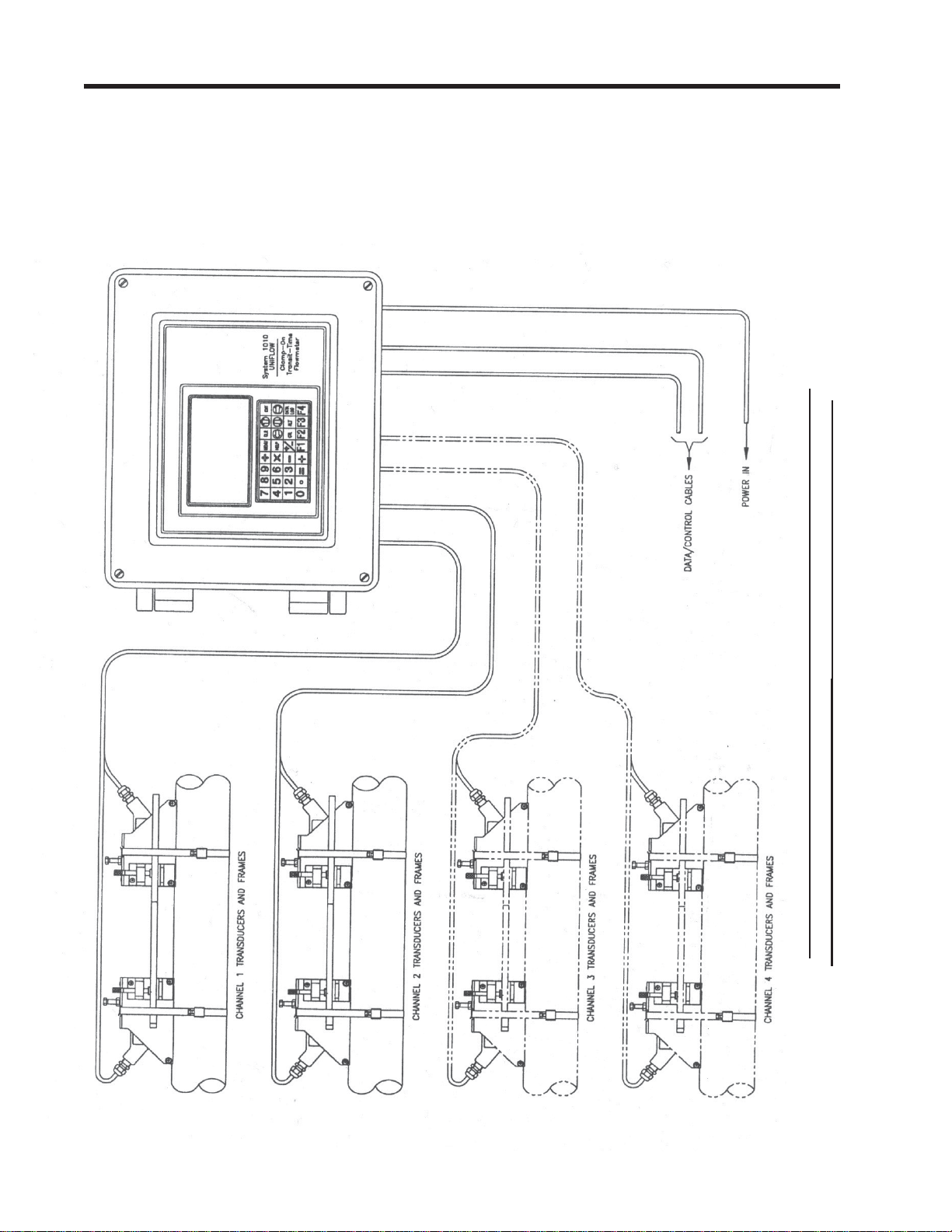
Flow Measurement Sub- system ( 4 channel system depicted here)
TYPICAL SYSTEM - 1010N PERMANENT CLAMP-ON SYSTEM
Page 23
1010NFM-3JSection 1
1.5 THE 1010N KEYPAD
The 1010N integral keypad provides 32 numeric and function keys (see table below). Use these keys to
enter, review or edit the site data. Certain keys control the graphics display, Datalogger and Totalizer.
“Blind Models,” having no keypad or display, must be setup by using their serial dat a port (see Appendix B).
KEYPAD FUNCTION CHART
KEY USAGE
MENU Press to activate the Installation Menu.
ENT Press <ENT> to store numeric data, select from option lists, etc.
LEFT, RIGHT ARROWS Menu navigation keys move cursor in respective directions.
UP, DOWN ARROWS Same as <Left> and <Right>. Also scrolls option list and graphic
display screen.
CLR Clear Key for erasing data, or selecting list options.
NUMBERS 0-9 Use to type numeric data.
DECIMAL POINT Use for decimal points in numeric data.
MATH OPERATORS Allows 4-function math operations in numeric entry cells.
“F” KEYS 1-3 Totalizer control and special function keys.
“F4” KEY CAUTION: SYSTEM RESET KEY (during power up)
CTL & ALT Used as shift keys for alternate key functions.
DATALOG Triggers immediate Datalogger report.
PLUS/MINUS [+/-] Changes the sign of numeric data.
NOTE: The keypad does not have alphabetic keys. Scrolling lists provide alphanumeric char-
acters as needed.
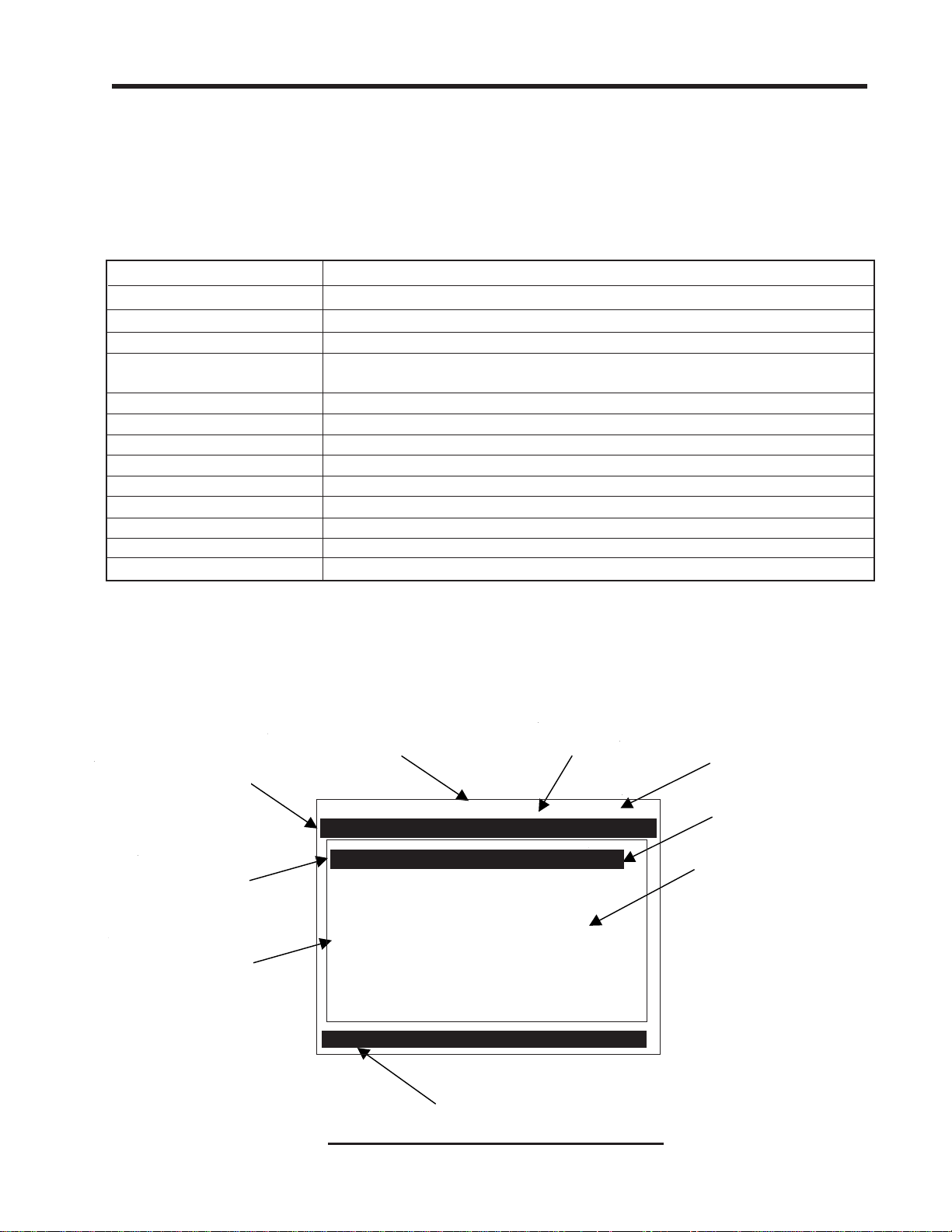
1.6 INTRODUCTION TO THE 1010N MENU SCREENS
The figure below shows a typical 1010N menu screen (in this case, the Pipe Data Menu).
Current Selected
Measurement
Channel
Site Name Identified
Highlighted Data
Menu Cell Data
(right-h and colu mn)
Menu Prompt Line
(Revers e V ideo )
Highlighted
Menu Cell
Menu Cell Data
(left-hand column)
Current Selected
Meter Type
Siemens 2 Channel [1] SITE 1
Select Pipe Class from Pipe T able
Select Pipe Class Manual Entry
Select Pipe Size No Pipes
Pipe OD <in> 0.500
Pipe Material Steel
Wall Thickness 0.100
Liner Material None
Liner Thickness 0.000
Pipe Dataiquid Class
Current Selected Menu
TYPICAL INSTALLATION MENU SCREEN
1-3
Page 24

1010NFM-3JSection 1
EXPLANATION OF THE CALL-OUTS
Menu Prompt Line When you select a menu cell, a highlighted text prompt appears on the top of
the screen to explain the function of the cell.
Current Selected [2 Channel] indicates Dual Channel meter operating mode selected.
Meter Type
Selected Channel The [1] indicates that measurement Channel 1 is currently selected.
Highlighted Menu The menu cursor (highlight bar) shows where you are currently working by
Cell reversing the display colors for that cell (white type on black).
Highlighted Data The right-hand column shows the current value highlighted. Pressing the
<Right Arrow> provides access to an option list or numeric field where you
can change the current value as required.
Menu Cell A menu cell is an individual location within a menu (in this case Pipe Data)
that stores a parameter (either a numeric entry or an option list selection.
Menu Cell Data The right-hand column shows the current value stored by left-hand column
menu cell. The Pipe Data Menu includes option list items and numeric entries.
Current Selected The highlighted bar at the bottom of the screen shows the name of the menu
Menu that you are accessing (e.g., Pipe Data).
1.7 HOW TO USE THE INSTALLATION MENU
This section introduces the System 1010 Installation Menu. It explains how to access and leave the
Installation Menu and how to enter site data. The Installation Menu consists of sub-menus, each providing individual menu locations (menu cells) that store site data. For convenience, this manual refers
to sub-menus simply as menus (e.g., the Pipe Data Menu). Shown below is the Clamp-on, Full Site
Setup screen for Channel 1 of a dual-channel meter. Single and four channel systems are identical.
Siemens 2 Channel [1]
Create-Name-Recall-Enable & Delete Site
Channel Setup
Pipe Data
Application Data
Pick/Install Xdcr
Operation Adjust
Flow/Tot al Units
Data Span/Set/Cal
Stripchart Setup
Datalogger Setup
I/O Data Control
Diagnostic Data
Clamp-on
1-4
Page 25

1010NFM-3JSection 1
1.7.1 ACCESSING AND LEAVING THE MENU
Upon first turning the meter on you see a Siemens graphic. This means that there is no active site
setup currently stored in memory . Note that this screen identifies the software version of the meter on
the upper right-hand corner of the display .
ver. 3.01.00
Software
Version
(x.xx.xx)
Make sure the keypad enable switch is in the correct position then press the <MENU> key to select the
menu. The first time you access the Installation Menu, you can leave it only by saving a site or by
turning the meter off. After installing and activating a site, use the <MENU> key to toggle between a
graphic display screen and the last accessed menu location.
Siemens 2 Channel [1] Channel 1
Select Meter Type
Meter Type >Dual Channel Flow
Meter Facilities Dual Beam Flow
Using the Menu Ch 1 + 2 Flow
Ch 1 - 2 Flow
Liquid Class
Top menu screen for dual-channel system Top menu screen for single-channel system
Siemens Site [1]
Select Meter Type
Meter Type Single Channel
Meter Facilities
When you press the <MENU> key , the cursor arrives at the first level of the installation menu. Refer to
the sample screens above. The left screen is from a dual-channel model. The right screen is from a
single channel model. Note that two columns, one on the left-hand side and the other on right-hand
side, divide the screen. The first left-hand item, [Meter T ype], is highlighted (white type on black). [Meter
Type] allows you to choose a meter configuration from the highlighted right-hand column list. With
single channel models, the only option is [Single Channel]. The next left-hand selection is [Meter Facilities]. Use the [Meter Facilities] menu to set global meter options and controls.
1.7.2 HOW TO ENTER DATA
The left-hand column shows the menu cells (described previously). Another way to think about lefthand column items is to consider them menu questions. Then you can see that the right-hand column
answers these questions. Right-hand column answers can be:
z Another series of menu cells (may become left column items when selected).
z An item from a scrollable option list (e.g., a class of liquids).
z A numeric entry (e.g., a pipe outer diameter).
z An alphanumeric string (e.g., a site name).
1-5
Page 26

1010NFM-3JSection 1
Selecting Items from an Option List
Examine the screen below. It shows how to use an option list to select a liquid for your application. How
to access this menu will be explained later. Note that the menu name [Application Data] appears
highlighted on lower left of the screen. Note also that the menu cell [Liquid Class] is highlighted - the
right-hand column shows the answer [Water 20C/68F].
Siemens 2 Channel [1] Channel 1
Select Liquid Class from Liquid T able
Liquid Class Water 20C/68F
T emperature Range -40F to 250F
Pipe Configuration Fully Developed
Anomaly Diams 10
Application Data
Pressing the <Right Arrow> changes the left-hand column to [Select Liquid]. Pressing the <Right Arrow> again accesses the option list. This expands the highlighted area to show the list contents. Note
that a cursor (arrow) points to the top item on the list.
Siemens 2 Channel [1] Channel 1
Access Liquid Option List
Select Liquid >Water 20C/68F
Estimated Vs m/s Water 50C/122F
Viscosity cS Water 75C/167F
Density SG ens Water 100C/212F
Water 125C/257F
Water 150C/302F
Water 175C/347F
Water 200C/392F
Water 225C/437F
Water 250C/482F
Acetic Acid
Liquid Class
The <Up and Down Arrows> scroll the option lists. Every press moves the cursor to the next item in
sequence. Due to the size of display screen, some option lists include more items than the display can
show. For example, on the screen above the last option shown is [Acetic Acid]. However , this option list
has more listings. Continue to press the <Down Arrow> to see more liquid selections. When you arrive
at the last item on a list, the next <Down Arrow> press brings you back to the top of the list; because
the option lists are of the “wrap-around” type.
To select an option list item, move the cursor to the item and then press the <ENT> key.This places
your selection at the top of the list and moves you out of the option list to the next menu cell. Examine
screen on next page. The option list item: [Diesel Fuel] has been selected. Note that this appears on
the right-hand column and that the highlighted area moves to the next menu cell in sequence: [Estimated Vs m/s].
1-6
Page 27

1010NFM-3JSection 1
Siemens 2 Channel [1] Channel 1
Access Liquid Option List
Select Liquid Diesel
Estimated Vs m/s 1600
Viscosity cS 2.00
Density SG 1.030
Liquid Class
Multiple Select Option Lists
Certain option lists allow you to make more than one selection. For instance, the Datalogger Data
option list allows you to select any or all of the available data items for your reports. You can use the
<Up and Down Arrows> to move the cursor through the list. If you press <ENT> to select an item, a
plus sign (+) appears next to that item. The cursor remains so that you can make other selections. To
deselect a previously selected item, move cursor next to that item and press <CLR>. Use <Left Arrow> to leave a multiple select option list.
Siemens 2 Channel [1] 1
Select Datalogger Data
Datalogger Mode +Site Id
Datalogger Data +Date
Log Time Interval +Time
Datalogger Events Flow
Display Datalogger +Average Flow
Raw Flow
Total
Liquid Class
Entering Numeric Data
When a menu cell requires a numeric answer, press the <Right Arrow> to access a number entry
field; an equal sign (=) appears before current entry . You can now use the number keys and the decimal point key to type a new value. If applicable, you can use <+/-> keys to change the mathematical
sign of the number. Press <ENT> to store the numeric data.
NOTE: All Numeric Data cells provide a four-function calculator via the keypad’s arithmetic
function keys.
Siemens 2 Channel [1] Channel 1
Enter pipe Outer Diameter manually
Select Pipe Class Manual Entry
Select Pipe Size N/A
Pipe OD (in) = 0.500
Pipe Material Steel Flow
Wall Thickness 0.100
Liner Material None
Liner Thickness 0.000
Pipe Data
1-7
Page 28

1010NFM-3JSection 1
Entering Alphanumeric Strings
An alphanumeric string is a series of numbers and letters; and also the Quotation Mark and the Pound
Sign symbol. You can also use a space. The meter uses these to identify a specific site setup or usermodified table. The 1010N keypad does not provide letter keys. However, when you access a menu
cell that requires an alphanumeric string answer, the menu cell right-hand column provides an eightcharacter entry field. Press the <Right Arrow> to access the field. This selects the first character
position. Note that the prompt changes to a question mark (?). With the cursor at the first character
position, use the <Up> or <Down Arrows> to scroll through a single-character list. For example, as
shown below, an <Up Arrow> at the first character position produces the letter: uppercase [A]. Pressing the <Right Arrow> moves the cursor to the second position.
Controlotron Dual Path Channel 1
Right Arrow & Enter Creates a new Site
Recall Site Setup
Channel Enable No
Create/Name Site ?A
Site Security Off
Delete Site Setup No Sites
Save/Rename Site
Channel/Path Setup
Use the <Right and Left Arrows> to move through the character positions. If you wish touse numbers
in your string, you can type them directly from the keypad. After you finish selecting your string, press
<ENT> to register it.
1.7.3 THE METER TYPE MENU
This is the first list presented upon entering the Installation Menu. Select the type of meter required for
your application. The meter automatically conditions Installation Menu choices to suit the selected
meter type. The following paragraphs introduce the available meter types for dual channel systems.
NOTE: On Single Channel systems, you do not get a choice of meter types, sincethis requires
two independent measurement channels. However, you can operate the single channel with any optionally supplied measurement technology. Some four channel models
provide four-path and channel summing operation.
1-8
Page 29

1010NFM-3JSection 1
Dual Channel
Dual Channel provides two independent measurement channels that operate simultaneously. Depending on the specific model, Dual Channel supports: Clamp-on Transit-time, In-line Transit-time,
Reflexor.
Channel 1
Flow
PIPE `A'
PIPE `B'
Channel 2
Flow
Pipe 'A' Flow Rate
Pipe 'B' Flow Rate
Dual Path
Dual Path uses two measurement channels to achieve a single output via a “virtual” third channel. The
resultant data is the average of the two channels. Only clamp-on or in-line transit-time operation allowed. Benefits include highest available precision and enhanced immunity to distorted flow profile
conditions.
Channel 1
Flow
Pipe
Ch1 + Ch2
2
Output
(average of
Ch 1 & Ch 2)
Channel 2
Flow
Channel 1+2 and Channel 1-2
Arithmetic operation produces data output via a virtual Channel 3, proportional to sum or difference of
the liquid and energy flow of two independent pipes. This requires setting the two channels to operate
independently . Only clamp-on or in-line transit-time operation is supported.
P
Channel 1
PIPE `A'
PIPE `B'
Channel 2
I
P
E
`
A
'
F
L
O
W
R
A
T
E
Ch1 [+/-] Ch2
E
T
A
R
W
O
L
F
'
B
`
E
P
I
P
Output
sum or difference
of Ch1 & Ch2
Channel 1-2 produces a data output via a virtual Channel 3, proportional to the difference of the liquid
and energy flow of two independent pipes. You have to set-up the two channels independently. Only
clamp-on or in-line transit-time operation is supported.
1-9
Page 30

1010NFM-3JSection 1
1.7.4 ESSENTIAL INFORMATION FOR USERS OF MULTI-CHANNEL 1010’s
Multi-Channel Meter Type
If your 1010 is a multi-channel model, it offers 2 or 4 independent measurement channels. The meter’s
resources are divided among these channels equally. This means that analog Input/Output, relays
and digital command lines will be fewer than for single channel machines. We’ll show you later how to
“get around” this limitation for times when you need all your multi-path meter’s resources for a single
measurement channel.
If one, two or three channels are running when you are trying to setup the last channel, it could take a
very long time for the setup; some 10 to 15 minutes should be expected. A great time saver would be to
turn each channel off after setup (setup one channel at a time) and reactivate all after everything is
setup; then the setup time goes very quickly .
Your datalogger and site storage memory, being bulky resources, are not divided up at all, and
remain available for each channel’s use. You will be able to save and recall sites to and from the
various channels as long as they share an identical measurement technology (Reflexor, clamp-on,
flowtube, etc.). Be aware, however, that moving a site from one channel to another like this, will likely
require a new initial installation to achieve its best potential. This is especially true if the new target
installation is not on the same pipe or uses another pair of transducers whose nominal characteristics
are identical. Note that datalogger reports will be interleaved in memory and their frequency is controlled by the interval that was selected for each channel. Providing each site with a unique name will
enable you to sort these out when analyzing the data later .
Arithmetic Operation
The dual channel instruments provide a modality of operation which permits the user to arithmetically
combine (through addition or subtraction) the results of the two independent measurement channels.
Installation of each channel is done via the dual channel menu. Site Saving and Recalling automatically recall the contributing sites. While the displays for each physical channel provide you all the data
(flow rate, totals, etc.) that are provided via independent channel operation, user Input/Output is largely
oriented toward the virtual channel - Channel 3.
Multi-Path Operation
In many cases, the performance of an ultrasonic transit time meter can be improved by allowing it to
interrogate the flow field with more than one beam. Imperfect flow profile conditions such as non-axial,
cross-flow or an off-center higher-rate flow core, which can cause a single path machine to mis-report
the flow rate, are often remedied in this way . The multi-p ath installation is similar to arithmetic operation; except for the fact that the virtual, or output channel has pipe dimension attributes (which in the
arithmetic meter channel it does not). This means that when you install a multi-path meter, pipe data
must be installed in Path 1 and Path 2. Your 1010 meter facilitates this by copying pipe data that you
installed as Path 1 and Path 2 data to the other paths. It is seldom, if ever , necessary to “trim” the pipe
data for the individual path channels - although you may install different size or type transducers for
each path. Once you define the pipe, move the menu to the individual paths using Select Path for the
physical installation of each channel. This is accomplished in the same way that individual channels
are installed.
Save and Restore Operations for multi-path sites execute on all the component channels simultaneously; the individual paths of multi-path sites do not have any existence or autonomy as
single channel sites. You will also find that individual path channels possess a reduced set of user-
accessible menu functions. For example, although you may zero each individual path, the meter
provides Kc control (slope correction) for the virtual channel (system channel) only. You will find that
the features and functions provide for each physical channel to focus mainly on the physical measure-
1-10
Page 31

1010NFM-3JSection 1
ment task. User output data, however, is mostly reserved for the virtual or system channel. This includes the totalizer functions. Analog data is largely reserved for the virtual or system channel as well
as the totalizer functions, analog outputs and datalogger. In some instances, access is also provided
to the path channel’s data in order to facilitate the gathering of diagnostic information; thus minimizing
menu clutter, but preserving as much functionality as practicable. Totalizer control via lead-in function
key is provided by F3 (dual-path meter) and, since there is no F5, F1 (four-path version). The Diagnostic Menu area has been similarly setup to provide data (Path 1, Path 2 and Path 1 and 2) generated by
the physical measurement channels when selected, but, to suppress elements only provided by the
virtual channel. As mentioned above, use a p artially installed multipath site in order to direct all meter
input/output to a single measurement path. Simply install the single available physical path and you’ll
produce data based on only this physical input and obtain the same functionality as provided to the
single channel user.
Selecting A Meter Type
The following example explains how to select a dual-channel clamp-on meter and initiate site programming for the measurement channel. Y our [Meter Type] selection, as well as other menu selections, are
“remembered” through power cycles.
NOTE: If you have a single-channel system, all you have to do is select a measurement tech-
nology and then go directly to Channel Setup. The site setup procedure for a singlechannel system is identical to setting up a measurement channel on a dual-channel
system.
As shown in the steps below , selecting this mode only requires key presses. This
is because dual-channel clamp-on is the default configuration for this instrument. To
select a different configuration, move the cursor to the desired Meter Type and then
press to select it.
ENT
Make sure that the keypad enable switch is in the [Enable-Up] position. T urn on power
and press to access the [Meter Type] screen. Refer to the figure below.
MENU
Note that on the left-hand column, [Meter Type] is highlighted as are all the available
meter types on the right-hand column. Press . This places a cursor next to [DualChannel Flow].
Siemens 2 Channel [1] Channel 1
Select Meter Type
Meter T ype >Dual Channel Flow
Meter Facilities Dual Path Flow
Ch 1 + 2 Flow
Ch 1 - 2 Flow
Pipe Data
1-11
Page 32

1010NFM-3JSection 1
Press the twice. This selects [Dual-Channel Flow] and then places the cursor next to
[Clamp-on] for Channel 1. Note that some models do not support all flow
Siemens 2 Channel [1] Channel 1
Choose Channel 1 Flowmeter Ty pe
Channel 1 >Clamp-on
Channel 2 FlowTu be
Reflexor
Dual Channel Flow
sensor types.
To select [Clamp-On] press . This selects the Clamp-On Installation Menu for Measure-
ment Channel 1. Note that the first menu, [Channel Setup], is highlighted.
Creating a New Site Setup (See paragraph 2.1.1)
The Channel Setup section of this manual provides detailed instructions on how to use all the Channel
Setup menu commands. This section provides an example of how to use the [Create/Rename Site]
command to create a new site setup. Always begin a new installation by issuing the [Create/Name
Site] command. Although you do not need to enter a site name to create a new site setup, you have to
provide one to save the site setup or to identify the source of logged data. In this example, we will use
[SITE1] for the site name.
To access the [Channel Setup] menu press then move the highlight down to [Create/
Name Site].
Siemens 2 Channel [1] Channel 1
Right Arrow & Enter Creates a new Site
Recall Site Setup No Sites
Channel Enable No
Create/Name Site
Site Security Off
Delete Site Setup No Sites
Save/Rename Site
Channel Setup
Press . Note that the cursor changes to a block, which appears after a question mark (?).
This indicates that you have accessed the first character position of an eight-character (max.)
alphanumeric entry field.
1-12
Page 33

1010NFM-3JSection 1
Siemens 2 Channel [1] Channel 1
Right Arrow & Enter Creates a new Site
Recall Site Setup No Sites
Channel Enable No
Create/Name Site ?
Site Security Off
Delete Site Setup No Sites
Save/Rename Site
Channel Setup
This block cursor is
cu r rently p laced at
the first character
position.
Press and hold . Note that the character position begins to scroll upward through the
alphabet of capital letters. Continue to scroll until block cursor shows [S]. Press .
NOTE: The character [S] remains at the first character position and the block cursor moves to
the second character position.
Siemens 2 Channel [1] Channel 1
Right Arrow & Enter Creates a new Site
Recall Site Setup No Sites
Channel Enable No
Create/Name Site ?S
Site Security Off
Delete Site Setup No Sites
Save/Rename Site
Channel Setup
Press and hold . Notice that the capitalized alphabet list begins to scroll downward through
the alphabet from [S]. Stop scrolling at letter [I]. Press to move the block cursor to the third
character position.
Scroll back up to letter [T]. Move the cursor to the fourth character position. Scroll down to letter
[E]. Move the cursor to the fifth character position. T ype [1] on the numeric keyp ad to complete
the site name.
Siemens 2 Channel [1] Channel 1
Right Arrow & Enter Creates a new Site
Recall Site Setup No Sites
Channel Enable No
Create/Name Site ?SITE1
Site Security Off
Delete Site Setup No Sites
Save/Rename Site
Channel Setup
Press to create the site setup named [SITE1]. Note that the name now appears in the
ENT
[Save/Rename Site] menu cell and on the upper right corner of the graphic screen.
1-13
Page 34

Siemens 2 Channel [1] SITE1
Use with Care -- Turn Security On or Off
Recall Site Setup No Sites
Channel Enable No
Create/Name Site SITE1
Site Security Off
Delete Site Setup No Sites
Save/Rename Site SITE1
Channel Setup
Flowmeter Installation Flowchart
1010NFM-3JSection 1
After creating a Site
Setup, the assigned
name app ears in
these places.
Flowmeter Installation
Collect Site
Data
Choose Mounting
Location For
Flowmeter and
Transducers
Prepare Pipe
Surface
Access
Installation
Menu
Enter Pipe
Parameters
Invoke
Transducer
Install
Procedure
Mount Transducers
on Pipe and
connect Flowmeter
Complete
Transducer
Installation Menu
Operations
Create a Site
1-14
Page 35

1010NFM-3JSection 1
1.8 USING FASTSTART SETUP
The dual-channel clamp-on mode offers a choice of using FastS tart Setup or Full Site Setup to create
your site setup. As its name implies, FastStart Setup is a quick way to start up the meter. FastStart
inserts default settings into all applicable menu cells. However, these can be edited later via the Full
Site Setup menu. In order to use FastStart Setup:
z Y our pipe must be included on the meter’s pre-set pipe table.
z Your liquid is water, or has similar sonic characteristics.
FastStart setup is actually a shortcut to these two menu locations (where dat a entry is mandatory for a
successful start-up):
z Pipe Data: The Pipe Data Menu is limited to the selection of pipe pre-sets only. There
are no provisions for manual pipe editing.
z Pick Install Xdcr: This is the same menu as Full Menu Setup (see paragraph 1.7).
1.8.1 CHOOSING THE PIPE CLASS/SIZE
Press to access [FastSt art Setup]. This selects [Choose Pipe Class]. There are over sixty English
and metric pipe sizes for eight different classes of pipes. Picking a pipe class and size automatically
sets all the required pipe parameters using industry standard dimensional data.
Press to access the Pipe Class option list. Note that although [Manual Entry] exists on this
list, it is inactive for FastSt art Setup (see p aragraph 2.2.1).
Siemens
In this example, we will pick the pipe class: [ASA Carbon Steel] by moving the cursor to the
selection and then pressing .
Siemens
ENT
1-15
Page 36

1010NFM-3JSection 1
Next, we will pick the pipe size: [1CS80] by moving the cursor to the selection and then pressing . This is all there is to setting up the pipe parameters.
ENT
Now, we will select and install the transducers.
Siemens
1.8.2 PICKING AND INSTALLING THE TRANSDUCERS
Press to access the Pick/Install Xdcr menu, then select the appropriate T ransducer Model. The
meter then analyzes your pipe data and registered transducer list before calculating the recommended
transducer size(s). The top-line prompt shows a series of transducer recommendations, that are
listed in order of priority from left to right. Select the appropriate transducer size with consideration
given to the computed transducer recommendations. In the example below we will install the “B3”
transducer size.
After you make your transducer selection, the meter automatically computes the preferred mounting
mode and transducer spacing index.
Siemens
NOTE: The meter only indicates the part number of the 1011 Universal Transducer mounting
track or spacer bar. It does not indicate this information for other transducer types.
Note the Number Index value.
This value corresponds to the index marked on the spacer bar or mounting track. The value of Ltn
represents the actual distance in inches or mm, between the front surfaces of the upstream and
downstream transducers.
1-16
Page 37

1010NFM-3JSection 1
Siemens
NOTE: You are allowed to override the transducer type and size mounting mode and spacing
offset. See paragraph 1.7.
Now you have to mount the transducers in accordance with the data recommended on the screen.
Refer to the Section 3 for detailed instructions. The pipe must be completely filled with a liquid for the
initial installation of the meter . Make sure that you do not install your transducers backwards or reverse
the Upstream and Downstream cables.
Siemens
Use the [Install Completed?] menu cell to inform the meter that you have finished mounting the
hardware. Press . Move the cursor to [Install]. Press .
ENT
The meter performs an Initial Makeup which conditions its operation to the selected transducer, pipe
and liquid and then sets the empty pipe and the zero flow levels automatically. Be patient! The Initial
Makeup performs a number of operations including a frequency sweep of the pipe wall resonance,
which could take several minutes.
Siemens
1-17
Page 38

1010NFM-3JSection 1
Upon completion, the meter reports the measured liquid sonic velocity . Press . The flowmeter will
then automatically perform an AutoZero operation, where the meter measures any zero flow offset,
which is used to correct the flow reading. This operation occurs only when the transducers are mounted
in the reflect configuration and is independent of whether or not the liquid is flowing.
After the AutoZero operation is complete, the meter may ask you to register the transducer used in this
installation. It is advisable that you register your transducers, since the registration list is used to
condition the transducer recommendation.
Press and select [YES], or [NO] if you do not want to register this transducer and then,
press .
ENT
Siemens
The meter is now ready to report flow. Press . The meter will then ask you to save the Site.
Saving the Site is optional and will therefore be covered in paragraph 1.7. To abort this item,
press . This brings up a Flow Display Screen.
Siemens 2 Channel [1] Channel 1
FLOW GAL/MIN
MENU
89.68
0.20
TOTAL KGAL Vs
0.12
Once your site has successfully installed, you can press to scroll between the available display screens.
The meter is now operational and the display will show flow by pressing the <MENU> key.
Now that you are familiar with the 1010N setup, take the time to read the information about the Installation Menu in Section 2. Becoming acquainted with the various flowmeter setups in the Main Menu will
help further your understanding of the 1010N.
1474
Vfo
G/M
0.00
1-18
Page 39

1010NFM-3JSection 1
A
1.9 1010WX CLAMP-ON LIQUID FLOWMETERS
The 1010WX flowmeter model numbers are listed below.
1010WX Series Flowmeters
1010WX
1010DWX
1010MWX
1010WX METER TYPES
The 1010WX series flowmeters are available in Single, Dual Path and Multi-Path versions. The
flowmeters may include a display providing flow rate, diagnostics data and keypad interface to access
on-screen software setup menus. Safety agency approved 1010WX series flowmeters have hazardous
area certification as indicated in the label example below.
NOTE: Graphic displays and local keypads are only available as options. The standard 1010WX
is not equipped with a graphic display or local keypad. Refer to Appendix B in this
field manual for hardware and software requirements for programming these models.
1010WX FLOWMETER LABEL
Blank unless flowmeter is rated suitable for hydrogen atmosphere. See
“System Hardware” description below.
CLASS 1, ZONE 1, AEx d [ia] IIB T5
EXPLOSION PROOF WITH I. S. OUTPUTS FOR CL I, GROUPS C, D, CL II, GROUPS E, F, G
ENCL. TYPE 4X IP66
CAUTION-DISCONNECT FROM SUPPLY BEFORE OPENING. KEEP COVER TIGHT WHILE
CIRCUITS ARE ALIVE. CONDUIT SEALS MUST BE INSTALLED WITHIN 18" OF THE ENCLOSURE
Exia
Associated
Apparatus
INSTALL PER CONTROLOTRON DRAWING 1010-443
CL I, DIV 2, GROUPS A, B, C, D SUITABLE FOR CL II, DIV 2, GROUPS E, F, G
+H2
B
RATING: 250 VAC OR 36 VDC MAX. 25 W
PPROVED
SYSTEM HARDWARE
ENCLOSURE:
The System 1010WX Series flowmeters have two available case configurations:
Standard 1010WX Case
The System 1010NWX Series flowmeter housed in a cast aluminum enclosure suitable for gas
groups up to and including hydrogen (Class 1, Zone 1, AEx d [ia] IIB +H2 T5).
Alternate Light Weight 1010WX Case
The System 1010WX Series flowmeter housed in a lightweight cast aluminum case suitable for gas
groups up to and including propane (Class 1, Zone 1, AEx d [ia] IIB T5).
1-19
Page 40

1010NFM-3JSection 1
ELECTRONIC MODULES:
All standard 1010DN and 1010MN flowmeter modules are available in the 1010WX series. See the
appropriate manual section for functionality of these modules.
DISPLAY AND KEYPAD OPTIONS
The standard 1010WX flowmeters are not equipped with a graphic display or local keypad. The local
display and keypad are options that can be combined with different case enclosure configurations,
which include the standard case with a window, the standard case without a window, the lightweight
case with a window and the lightweight case without a window.
CAUTION: Consult local codes for permit needed to setup units using the graphic display and
local keypad. Setup must be done with cover opened.
978
5
4
361
2
0
Standard Case Enclosure with Window including the 1010WX equipped with optional graphic
display and local keypad.
978
5
4
361
2
0
Standard Case Enclosure without Window including the 1010WX equipped with optional graphic
display and local keypad. (Shown with cover
opened.)
1-20
Page 41

Section 2
1010NFM-3J
2. THE 1010N INSTALLATION MENU
Programming System 1010N requires no special experience or training. This field manual contains all
the necessary information. If you intend to connect this instrument to an external device, then please
have the instruction manual for the device available for reference. The following paragraphs present a
generic menu reference that applies to all configurations of 1010 NEMA meters. Please refer to the
Reflexor and Flow Tube sections for instructions specific to those operating modes.
This section contains a general description of how to enter site setup data via the 1010N Installation
Menu. It assumes that you have already selected a meter type as described in the Getting Started
section. For convenience, it presents the Installation Menu in the same sequence as it appears on the
menu screen. Please note, however, that it is not necessary to program the meter sequentially.
The conventions used with these instructions are:
z When the text refers to a keypad key, it will be enclosed in “less than” (<) and “greater than” (>)
symbols: e.g., <MENU>, <ENT>, <Up Arrow>, etc. Where a visual of the key is shown; this means
press this key.
z When the text refers to a menu or menu cell name, it will be enclosed with square brackets: e.g.,
[Pipe Data], [Channel Enable], etc.
z Each menu includes an image of its main screen and a diagram of its structure. The rightmost
column of the structure diagram lists the option list choices of the menu cell, if applicable.
General Installation Menu Notes:
z If a power failure occurs while you are entering or editing data, the entered data may not be retained
in Active Memory.
z Although you can operate the meter immediately after completion of the site setup, we recommend
that you preserve your settings by saving them under a site name. Site data can be saved at any
time before invoking either the [Recall Site Setup] or the [Create/Rename Site] commands. When
issued, these commands overwrite all data present in Active Memory .
z We do not recommend that you attempt to operate the flowmeter at a new site by recalling and then
editing an existing site setup. Each site must have its own set of transducer install parameters,
even if the data from the recalled site setup is identical. Always issue the [Create/Rename Site] to
begin a new site setup. This will fill all the menu cells with defaults to eliminate the possibility of
retaining unwanted parameters.
z The meter allows you to create your own personal site setup defaults. After creating asite setup
and editing default parameters as desired, save the site using the name [FASTSTRT]. The next
time you issue the Create/Name Site command, your custom parameters will become the system’s
defaults.
2-1
Page 42

1010NFM-3JSection 2
2.1 THE CHANNEL SETUP MENU
Available after picking a meter type and a measurement technology. Use this menu to manage site
setups. You can create, recall, delete and save entire site setups. You can apply Site Security, which
permits read-only access to the Installation Menu unless you enter a password. The Channel Enable
switch allows you to disable and enable a measurement channel. *Be aware that Site Name option
lists only show sites that are consistent with the currently selected meter type.
CHANNEL SETUP MENU STRUCTURE
Channel Setup Recall Site Setup *Site Name List
Channel Enable Yes
Create/Name Site *Site Name Entry/Edit
Site Security O f f
Delete Site Setup Site Name List
Save/Rename Site *Site Name Entry/Edit
No
On
This shows that
the Meter Type is
Dual Channel,
operatin g w it h
Channel 1 ac t i ve.
This shows that
the site setup
[XYZ] is the active
site.
Siemens 2 Channel [1] XYZ
Scroll saved Site Setup list and Enter
Recall Site Setup XYZ
Use this menu cell to create and
name a site setup. Note that the
cell retains the name of the
most recently created site setup
[XYZ].
Use this menu cell at any time
to manually save the site data.
Note that attempting to leave
the menu aft er entering/ editing
any site data triggers a Save
Site pop-up window
automatically.
Channel Enable Ye s
Create/Name Site 1
Site Security Off Flow
Delete Site Setup 1
Save/Rename Site 1
Channel Setup
Use this menu cell to free up site storage
memory by deleting obsolete site setups.
Note that the cell retains the name of the
most recently created site setup [XYZ].
This opti on lis t expands as you s ave m ore
sites.
This cell shows that
site setup [XYZ] is
stored in memory,
and can be recalled.
This opti on lis t
expands as you save
more sites.
Use this menu cell to
enabl e or dis abl e S it e
Security. Provide a
password to enable.
Re-enter the
password to disable.
2.1.1 HOW TO RECALL A SITE SETUP
The Recall Site command allows you to reinstall the system at a former site. For an original installation, see Create/Name Site for instructions on how to create a new Site Setup. This menu cell provides
a list of saved site names. Scrolling to a site name and pressing <ENT> moves all the parameters
associated with that name into Active Memory.
If there are no site setups present in site storage memory , the menu cell reports [No Sites] in the righthand column. Saving a site setup with a site name adds the name to this option list. The first selection
2-2
Page 43

Section 2
1010NFM-3J
on the list is the currently active Site Setup. The system will be ready for operation after you install the
transducers and make the required hardware connections. Note that the installed transducers must
comply with the recalled site parameters.
To recall a Saved Site Setup: (Where a visual of the keys is shown; this means press this key)
To access the list of saved site names press
To move the cursor to the Site Name press
Press .This triggers a pop-up window that asks if you intend to use the original transducer
ENT
position (recommended). This means that you have to remount the transducers exactly as they
were in the previous install.
If you cannot recreate the original transducer installation, then press to change the pop-up list
from [Original] to [New].
Press . This disables the measurement channel until you repeat the Pick/Install Transducer rou-
ENT
tine.
2.1.2 HOW TO ENABLE AND DISABLE A MEASUREMENT CHANNEL
The flow computer disables a measurement channel until the completion of the required Site Setup
entries and the transducer installation procedure. The meter enables the measurement channel automatically after it receives all required site data and completes the transducer install routine. (The Site
Enable menu cell allows you to disable or enable a measurement channel after there has been a
successful transducer install).
The system does not require your presence for routine operation. If a fault condition (e.g., an empty
pipe) disrupts operation, the system will recover automatically after the fault clears. Use Channel Enable [No] to turn off a channel that is currently unused but active; for example, if the transducers have
been removed for servicing.
To disable a channel that is operating:
To access the [Channel Enable] option list press
Move the cursor to [No] by pressing
To disable the measurement channel press
To enable a channel:
To access the [Channel Enable] option list press
Move the cursor to [Yes] by pressing
To enable the measurement channel press
ENT
ENT
2-3
Page 44

1010NFM-3JSection 2
2.1.3 HOW TO CREATE/NAME A SITE SETUP
Use this command to create a new Site Setup. This is the first action required for an original installation. Create/Name Site inserts system defaults in all the appropriate menu cells. You can edit these
defaults as necessary to suit your needs.
Y ou do not have to provide a site name in order to create a new Site Setup. Y ou can create a site simply
by pressing the <Right Arrow> to access the menu cell entry field and then pressing <ENT>. This
creates a “nameless” Site Setup. However, if you intend to use the meter’s multi-site storage facility,
you must enter a unique site name for each site setup you want to retain in site storage memory.
To Create and Name a new Site Setup:
To access the first character position press
To select a character press then to highlight to next character position.
To select the second character press
Repeat this process to select all the characters (8 max.) you want to use to identify the new Site
Setup.
To create the new Site Setup press
ENT
NOTE: If you decide to use numbers in the site name, you can type these characters directly
from the keypad.
2.1.4 HOW TO ENABLE/DISABLE SITE SECURITY
With Site Security enabled, the meter will require a password before it allows any activity that could
interrupt or affect system operation. You can still access the Installation Menu. However , Site Security
limits access to the viewing of parameters only . In other words, you will still be able to review site dat a,
but you will not be able to make any changes.
Activate Site Security with care. Once activated, the only way to deactivate it is via the Site Security
[Off] command. However, the cursor will not move to the Site Security option list until you enter the
correct password. Therefore,
way to deactivate Site Security without knowing the password is to return the unit to Siemens. However, the process the factory uses to remove Site Security will eliminate any existing Site Dat a as well.
The flowmeter will allow a <F4> Reset Sequence when Security is active, however, it also cont ains a
Menu Enable switch that allows you to inhibit this function (see drawing 1010N-7).
CAUTION: MAKE CERTAIN THAT YOU RETAIN A COPY OF THE PASSWORD IN A SE-
CURE LOCATION.
it is essential that you never forget or misplace the password. The only
To activate Site Security:
To access [Site Security] option list press
To scroll the option list to [On] press then . [Enter Code?] appears at
ENT
the top of the display screen.
2-4
Page 45

Section 2
To select the first character, use the numeric keys or press . To move the cursor
to the first character position press .
To move the cursor to the second character position press .
Repeat the selection process for the second character. Continue this process until all the
required characters (8 max.) appear in the field.
1010NFM-3J
To store code press . [Confirm Code ?] appears at top of the display screen. Retype
ENT
code exactly as described above.
Press . This moves the cursor to the [Site Security] option list.
ENT
To scroll the option list to [Site Security: On] press . Once you turn on Site Security, you must enter the correct code to turn it off.
To activate Site Security press .
ENT
2.1.5 HOW TO DELETE A SITE SETUP
If you attempt to save a Site Setup when memory is full, the screen will show [Memory Full]. If you get
this message after issuing a Save/Rename Site command, you’ll have to delete an unneeded Site
Setup to clear memory space. The Datalogger and Site Storage share a common memory pool, so a
large amount of logged data could also trigger the [Memory Full] message. For how to clear Datalogger
memory , see [Meter Facilities/Datalogger Control]. The Defragment Command may also secure more
memory (see Meter Facilities/Memory Control Menu).
To delete a stored Site Setup:
To highlight [Delete Site] press .
To access the [Delete Site] option list press .
Move the cursor to the site name of the site setup you want to delete.
To delete the obsolete site setup press .
ENT
2.1.6 HOW TO SAVE/RENAME A SITE SETUP
The Save/Rename Site command copies data from Active Memory to the Site Storage Memory . Saved
Site Setups can be recalled for future use. This menu cell allows you to save a Site Setup at any time
during the programming process. However, you must recall and complete the Site Setup in order to
achieve operation.
When you access the Save/Rename Site menu cell, the name of the most recently created Site Setup
(see Create/Name Site) appears automatically. If this name is acceptable, you can press <ENT> to
save the Site Setup. You can change the listed site name by following the procedure below. You may
select up to eight characters. If you decide to use numbers or a decimal point in the site name, you can
type these characters directly from the keypad.
2-5
Page 46

1010NFM-3JSection 2
To Save or Rename a Site Setup:
To access the first character position press
To select a character press then to highlight to next character position.
To select the second character press . Repeat this process to select all the
characters (8 max.). To save the site data present in Active Memory press .
ENT
2.2 THE PIPE DATA MENU
This menu becomes available after picking a Meter Type, Measurement Channel and Measurement
Technology. We recommend that you edit the Pipe Data immediately after creating a new Site Setup.
The Pipe Data menu allows you to define the application’s pipe parameters. Select a pipe from one of
the meter’s stored pipe tables (see menu structure below); or input the pipe size and description
manually. Manual entries include Pipe Material, Outer Diameter (OD) and pipe Wall Thickness. Liner
Material and Liner Thickness entries are included to support pipes with liners. The meter requires the
pipe outer diameter (OD) and wall thickness to operate. You must define these parameters to complete the installation.
The pipe table includes descriptions for over sixty standard pipes plus any user-entered pipes (see
Meter Facilities). To use these presets, first pick a Pipe Class (e.g., ASA Stainless Steel), then pick a
pipe size within that class (e.g., 4SS10). When you select a particular pipe class/size, the relevant pipe
parameters appear in the Pipe Data menu cells. If a given pipe class/size does not match your application exactly you can still edit each individual parameter to fine-tune your selection. In addition, the Meter
Facilities section of the Installation Menu provides a pipe table editor that allows you to customize any
or all of the stored pipe tables.
NOTE: If you edit the pipe parameters after the system is operating, you will have to repeat
the transducer install procedure.
Use this menu
cell to edit the
pipe outer
diameter.
Use this menu
cell to edit the
pipe mat eri al.
Use this menu
cell to edit the
wall thickness.
Siemens 2 Channel [1] A BC
Select Pipe Class from Pipe T able
Select Pipe Class Manual Entry
Select Pipe Size No Pi pe s
Pipe OD <in> 0.500
Pipe Material Steel
Wall Thickness 0.100
Liner Material None
Liner Thickness 0.000
Use this menu cell to select a Pipe
Class fr om on e of the m et er's pr es ets .
The [Manual Entry] selection (default)
means th at you ent er pipe dat a
manually.
After picking a pipe class,
use this menu cell to
select a pi p e fr om within
that class.
Use this menu cell to
select a pipe liner
material.
Use this menu cell to edit
the pipe liner th ickness.
Pipe Data
2-6
Page 47

Section 2
THE PIPE DATA MENU STRUCTURE
Pipe Data Select Pipe Class Manual Entry
Select Pipe Size Manual Entry Set pipe parameters manually
Pipe OD (in / mm) xx.xx (numeric entry). Auto if specific pipe is selected)
1010NFM-3J
ASA Stainless Steel*
ASA Carbon Steel
ASA Plastic
Metric DN Steel
Metric SGP Steel
Cast Iron Table
Ductile Iron T able
Copper Tube Table
ASA Stainless Steel* ASA Carbon Steel ASA Plastic
1SS10 1CS40 1P40
2SS10 1CS80 1P80
3SS10 2CS40 2P40
4SS10 2CS80 2P80
6SS10 3CS40 3P40
8SS10 3CS80 3P80
Metric DN Steel 4CS40 Steel 4CS40
50 DN 4CS80 4P80
100 DN 6CS40 6P40
200 DN 6CS80 6P80
400 DN 8CS40 8P40
800 DN 8CS80 8P80
Metric SGP Steel 10CS XSteel 10P XS
20A-SGP 10CS40 10P40
25A-SGP 12CS STD 12P STD
32A-SGP 12CS XS 12P XS
40A-SGP 16CS STD 16P STD
50A-SGP 16CS XS 16P XS
65A-SGP 18CS STD 18P STD
80A-SGP 18CS XS 18P XS
90A-SGP 20CS STD 20P STD
100A-SGP 20CS XS 20P XS
125A-SGP 24CS STD 24P STD
150A-SGP 24CS XS 24P XS
175A-SGP 30CS STD 30P STD
200A-SGP 30CS XS 30P XS
225A-SGP 36CS STD 36P STD
250A-SGP 36CS XS 36P XS
300A-SGP Cast Iron Table Ductile Iron Table
350A-SGP 6” cls C 6” cls 52
400A-SGP 10” cls C 8” cls 52
450A-SGP 12” cls C 10” cls 52
500A-SGP 16” cls C 12” cls 52
Copper Tube Table 20” cls C 16” cls 52
1” type M 24” cls 52
1” type K
1” type L
2” type M
2” type K
2” type L
4” type M
4” type K
4” type L
6” type M
6” type K
6” type L
*Note: The highlighted selection in the above table illustrates how to choose the ASA Stain-
less Steel Pipe Class and all its available Pipe Size selections. All other Pipe Classes
(e.g., ASA Carbon S teel) listed can be selected in the same manner.
2-7
Page 48

THE PIPE DATA MENU STRUCTURE (continued)
Pipe Data (cont.) Pipe Material Steel
Wall Thickness x.xxx (numeric entry)
Liner Material None
Liner Thickness x.xxx (numeric entry)
ABS
Aluminum
Black Iron
Brass
Cast Iron
CuNi (70/50)
CuNi (90/10)
Copper
Ductile Iron
FRP
Glass
Hastelloy
Inconel
Nickel
Polyethylene
PVC (Plastic)
Silicone
Teflon
Titanium
Cement
Coal T ar
Enamel
Glass
Plastic
HDPE
Teflon
Rubber
1010NFM-3JSection 2
2.2.1 HOW TO SELECT A PIPE CLASS
The 1010N pipe tables are arranged by classes of common type and material. The default selection is
[Manual Entry]. As its name infers, you would use this selection to manually enter individual pipe parameters.
To select a Pipe Class:
To access the [Pipe Class] option list press
To scroll through the available classes press
To select the class that fits your application press
ENT
When you pick a Pipe Class, the Select Pipe Size menu cell (see below) presents the pipe size option
list associated with the selected class. By using the pipe class and pipe size option lists, you automatically load all the required pipe information. You can also select a pipe class/size, then edit any of the
associated defaults to fine-tune the pipe data.
NOTE: Create custom pipe data via the Pipe Table editor in the Meter Facilities menu.
2.2.2 HOW TO SELECT A PIPE SIZE
Selecting a Pipe Size installs the selected pipe parameters into the balance of the Pipe Data menu
cells and prepares the 1010 for Transducer selection and Inst allation. This option is not applicable if the
Pipe Class is [Manual Entry].
2-8
Page 49

Section 2
After selecting a pipe class:
To access the [Select Pipe Size] option list press
To scroll to the required pipe press
1010NFM-3J
To register selection press
ENT
2.2.3 HOW TO ENTER THE PIPE OD (in. or mm.)
Use this menu cell to edit the pipe outer diameter. Be aware that you will not be able to complete the
transducer installation successfully unless this information is accurate. In addition, if you change this
parameter on a previously installed site, you will have to repeat the transducer installation. Note: Use
actual pipe dimensions, not ASA code or any other standard. The English/Metric selection in the Meter
Facilities menu determines whether these dimensions are in inches or millimeters.
To enter the Pipe OD:
To enable numeric entry press
Use the keypad’s numeric keys to type the exact outer diameter of the pipe in inches or millime-
ters.
To register the Pipe OD press
ENT
2.2.4 HOW TO SELECT A PIPE MATERIAL
The pipe material selection affects flow calibration to a small degree. It also influences the metergenerated transducer size and spacing recommendations. Select a substitute material if you do not
find the material of your pipe in the pipe table. You can edit each pipe parameter to achieve a closer
match. If you change any pipe parameters, after running the Transducer Install procedure, you may
have to re-space the transducers. The Pipe Material option list provides a selection of common pipe
materials. The default pipe material is S teel. Press <Down Arrow> to accept the default setting for this
menu cell.
To select a Pipe Material:
To access the [Pipe Material] option list press
To scroll to the required pipe material press
To register selection press
ENT
2.2.5 HOW TO ENTER THE WALL THICKNESS
The wall thickness of the pipe is one of the required parameters. The flow computer needs this data to
generate accurate transducer size and spacing data recommendations. Selecting a pipe class/size
inserts a wall thickness value. If this data is inaccurate, then use this menu cell to set the pipe’s wall
thickness (in English or Metric data units).
2-9
Page 50

1010NFM-3JSection 2
NOTE: Do not use ASA schedule code to specify the wall thickness. You must enter actual
dimensions.
To enter the Pipe Wall Thickness:
To enable numeric entry press
Use the keypad’s numeric keys to type exact wall thickness (use in/mm).
To register the pipe wall thickness press
ENT
2.2.6 LINER MATERIAL
For lined pipes, select a pipe liner from the material option list. If the pipe liner material does not appear
on the list then select the closest type available. If necessary, call Siemens Customer Service for
additional help. The system default Liner Material is [None]. If the pipe does not have a liner , press the
<Down Arrow> twice to bypass to the next two menu cells. The [Liner Material] option list offers a
selection of common liner materials.
To select a Liner Material:
To access the [Liner Material] option list press
To scroll to the required Liner Material press
To register selection press
ENT
2.2.7 LINER THICKNESS
If you specified a pipe liner in the [Liner Material] menu cell, then use this menu cell to set its exact
thickness in appropriate units (English or Metric).
To enter a Liner Thickness:
To enable numeric entry press
Use the number keys to type the exact line thickness value.
To register the data press
ENT
2.3 THE APPLICATION DA T A MENU
This Menu becomes available after picking a Meter Type, Measurement Channel and Measurement
Technology. Use of this menu is optional.
CAUTION: An erroneous Viscosity entry could affect the meter’s intrinsic calibration. Do not
alter the default viscosity value of your liquid unless you are sure of your data.
Use the Application Dat a menu to edit default settings to match your application. When you specify a
Liquid Class, the meter will adjust its operation to accommodate the liquid’s estimated sonic velocity,
viscosity and specific gravity. If necessary, you can edit each liquid class parameter individually to
obtain a closer match with the liquid. The default liquid is W ater at 68
2-10
°F (20°C).
Page 51

Section 2
1010NFM-3J
The Temperature Range menu cell allows you to specify the expected temperature range at the transducer mounting location. The default setting: [-400F to 2500F], matches the standard 991 and 1011
series of transducers but not the 101 1H. For higher pipe temperatures, selecting the proper temperature range allows the flow computer to recommend the appropriate transducers.
Use this menu to select
a cla ss of liquids and
option all y ed it the
following liquid
parameters:
Estimated Vs
•
Viscosity
•
Density
•
(Specific Gravity)
Use this menu cell to
select an upstream
pipe compensation
correction table.
Siemens 2 Channel [1] Channel 1
Select Liquid Class from Liquid Table
Liquid Class Water 20C/68F
UniMass T able Create/Edit Table
Temperature Range -40F to 250F
Pipe Configuration Fully Developed
Anomaly Diams 10
Application Data
The UniMass Table is
used to associate the
metered liquid’s current
temper ature and s onic
velocity with its specific
gravity an d vis cosit y.
Use this menu cell
to specify the
temperature range
of the liquid.
Use this menu cell to enter
the number of pipe
diameters between the
upstream configuration and
the transducer installation.
APPLICATION DATA MENU STRUCTURE
Application Data Liquid Class Select Liquid 20% Ethylene Glyclol
50% Ethylene Glyclol
27% CaCl Brine
Water 13C/55F
Water 20C/68F
Water 50C/122F
Water 75C/167F
Water 100C/212F
Water 125C/257F
Water 150C/302F
Water 175C/347F
Water 200C/392F
Water 225C/437F
Water 250C/482F
Acetic Acid
Alcohol
Bromine
Carbon Tet
Chlorine
Diesel Fuel
Gasoline
Glycerine
Kerosene
MEK
Oil (SAE 20)
Sea Water
Toluene
Trichloroethyl
Other
(continued)
2-11
Page 52

APPLICA TION DAT A MENU STRUCTURE (continued)
Application Data Liquid Class Viscosity cS x.xx (numeric entry)
UniMass T able Disabled
Density SG x.xxx (numeric entry)
Constant T emp Create/Edit T able T able Point Ne w
Constant Vs Create/Edit Table T able Point Ne w
Clear T able No/Y es
T able Active Y es/No
Clear T able No/Y es
Changing T emp & Vs Table Active Y es/No **
T emp Range -40F to 250F
Pipe Config Fully Developed***
(Change to Up- 1 Elbow
stream Piping) Dbl Elbow +
Anomaly Diams xxxx (numeric entry)
-40F to 375F
-40F to 450F
Dbl Elbow V alve
Expander
Reducer
Norm Entry
Header Inlet
Intrusions
T able Active Y es/No
1010NFM-3JSection 2
Vs xx.xxx
S.G. xx.xx
Viscosity (cS) x.xxx
Accept Yes
Temperature xx.xxx *
S.G. x.xxx
Viscosity (cS) x.xxx
Accept Yes
Clear Pt.
Clear Pt.
* Must recognize degrees C, degrees F selection.
** Vs, SG and Viscosity must be greater than 0.0. Enable permitted only after table contains at least
two entries of correctly formatted data.
*** Pipe Configuration Default.
NOTE: The currently active table will be shown highlighted next to the [UniMass Table] menu
cell. If no table is active then [Disable] will appear highlighted next to the [UniMass
Table] menu cell.
NOTE: The [Changing Temp & Vs] lookup table must be serially loaded using the HyperTermi-
nal “Send Text” command. This table can be generated using a utility provided by
Controlotron, which converts the Vs and temperature data into a uniform 10x10 grid
array and formats it appropriately for serial download.
2-12
Page 53

Section 2
1
1010NFM-3J
2.3.1 HOW TO SELECT A LIQUID CLASS
The liquids listed in the [Liquid Class] option list are representative samples of the class of liquids to
which they belong. Selecting a named liquid fills in the Estimated Vs (m/s), Viscosity (cS), and Density
(SG) parameters automatically . However , you have the option of editing these parameters individually
to fine tune the liquid settings. If you do not find a liquid that matches your application, then you can
select [Other]. This selection will not provide a liquid name or automatic parameter entry. Only Ethylene Glycol (20 & 50%), CaCl Brine (27%) and all water entries provide energy metering services.
Use this menu cell
to select a liquid.
Selecti ng a li qui d
automat ically ent ers
data into Liquid
Class menu cells.
Use this menu cell to
edit the specific
gravity of th e liquid.
Siemens Dual Path A BC
Access Liquid Option List
Select Liquid Water 20C/68F
Estimated Vs m/s 1482
Viscosity cS 1.00
Density SG 1.000
Liquid Class
Use this menu cell to edit the
Estimated Vs ONLY if you are
sure of a more accurate value.
This will reduce the chances of
a re-spacing request for clampon flow transducers during the
install pr oc ed ur e.
Use this menu cell to edit
the liquid viscosity ONLY
if you are certain that th e
data you enter is
accurat e. A n err on eous
entry coul d affect met er
calibration.
To select a Liquid Class:
To access the option list press
Scroll through the list to find the closest match to the application’s liquid.
To register selection press
ENT
How to Edit the Estimated Vs (liquid sonic velocity)
During transducer installation, the flow computer bases its initial transducer spacing recommendation
on the value stored in this menu cell. Estimated Vs m/s allows you to review and modify (if necessary)
the Vs value for the liquid class you selected.After you install the transducers, the computer will measure Vs directly . If the displayed (or edited) Vs stored in this menu cell is accurate, the transducers will
be spaced correctly. This will eliminate the need to re-space the transducers after their initial installation. However, if the estimated Vs is subst antially different from the measured value, the computer will
request you to re-space the transducers during the transducer install procedure.
NOTE: During the Xdcr install procedure (see paragraph 2.4), you can ignore a respacing
request by pressing the <Down Arrow> instead of <ENT>. If this triggers a Spacing
Alarm, check [Diagnostic Data/Site Setup Data] to make sure the measured Vs value
does not exceed the Vs max or Vs min items.
To edit the Estimated Vs m/s:
To activate numeric entry press
Type the sonic velocity value using meters-per-second.
To register the data press
ENT
2-13
Page 54

1010NFM-3JSection 2
How to Edit the Viscosity (cS) Setting
The [Viscosity cS] menu cell shows the kinematic viscosity of the selected liquid (in centistokes). The
viscosity value is particularly important for high viscosity liquids. The meter requires an accurate liquid
viscosity to compute the flow profile compensation. If the displayed viscosity is correct, bypass this
menu cell by pressing the <Down Arrow>. Please be aware that the viscosity of the liquid affects the
Reynolds Number compensation applied to the final rate output. Therefore, inaccurate data could
cause flow data errors. Edit this entry only if you know the true viscosity of your liquid. If necessary , our
Technical Service Group can provide reliable viscosity data for most liquids.
To edit the Viscosity setting:
To activate numeric entry press
Use the numeric keys to type the Viscosity value, which must be in centistokes.
To register the data press
ENT
How to Edit the Density (SG) Setting
Use the [Density SG] menu cell to edit the nominal specific gravity of the selected liquid. This allows the
flow computer to provide a flow rate output in mass units, if required. This mode suits applications
where the density is not only known, but also fixed, due to well-controlled liquid temperature and chemistry . The default specific gravity setting is 1.000. The flow computer uses the liquid’ s specific gravity to
form a multiplier for the conversion of volumetric flow to mass flow. Mass flow appears (in selected
units) on the display screen. [Density SG] (as it applies to this system) is defined as the ratio of the
mass of this liquid to the mass of an equal volume of water at 20°C or 68°F.
To edit the Density SG setting:
To activate numeric entry press
Use the numeric keys to type the Density SG value.
To register the data press
ENT
2.3.2 UniMass TABLE
Some 1010 family meters provide a feature we call UniMass. These meters support a UniMass Table
which associates the metered liquid’s current temperature and sonic velocity (Vs) with its specific
gravity and viscosity. These variables are then used to provide mass metering and real-time flow
profile compensation based on Reynold’s numbers. For hydrocarbon liquids requiring standard volume compensation, a 1010DV flowmeter should be specified.
Note that the UniMass option will provide value to the extent that the table is accurately prepared for
your particular liquid and installed correctly . The t able scanning routine can function with as few as two
(completely) defined data points. If the sensed variable(s) assume values beyond the table limits, the
routine does not extrapolate, but rather produces “flat” or “clipped” data, assuming the value of the last
valid table entry.
2-14
Page 55

Section 2
1010NFM-3J
The table is built by inputting a series of data points—two inputs and two outputs each:
z Input data consists of sonic velocity (Vs) and temperature.
z Output data consists of specific gravity (S.G.) and viscosity (cS) at the specified Vs and tem-
perature.
Ideally , each point contains four empirically derived values. However , when enough data exist s to permit it, the table editing routine interpolates missing values based on prior user-entered data.
The UniMass feature expands the basic utility of the flowmeter by synergistically combining its ability to
measure sonic velocity and temperature with user-provided data regarding the process liquid or family
of liquids. The resulting instrument is virtually a liquid analyzer , in addition to measuring mass flowrate
and automatically compensating for viscosity variation.
UniMass Table operations are most successfully employed when the application liquids or family of
liquids are fairly well-controlled. Basic table data can be obtained by a variety of means:
z From handbooks of physical or chemical data.
z Directly measured in the laboratory using your 1010, its RTD temperature sensor and a non-
flowing measurement cell (standpipe).
z After installation on the process pipe if specific gravity and/or viscosity data regarding the liquid
can be locally obtained via samples or from on-line instrumentation.
Although the UniMass Table is designed to permit both temperature and sonic velocity to be active
input variables, UniMass provides Constant Vs and Constant Temp table editing capabilities as well.
The resulting lookup function then associates specific gravity and/or viscosity with either temperature
or sonic velocity only .
APPLICATION DATA MENU EXPLANATIONS FOR UniMass TABLE
The UniMass Table resides within the Application Data menu, however, in Flow Tube (FT) instrument s
it resides within the [Liquid Data] menu.
[UniMass Table] - Press the <Right Arrow> to access the UniMass data point editor.
[Disable] - Press the <Right Arrow> to access tables and enable UniMass routine.
The currently active table will be shown highlighted next to the [UniMass Table] menu cell. If no table is
active then [Disable] will appear highlighted next to the [UniMass Table] menu cell.
[Constant Temp] - Press the <Right Arrow> to access. The [Constant Temp] UniMass Table can be
used for multiple liquid applications with tightly controlled constant temperature or single liquid applications with varying temperature (ideal if temperature is not measured).
This function simply associates changes in liquid sound velocity with changing SG and Viscosity.
2-15
Page 56

1010NFM-3JSection 2
z Create/Edit Table Point [New Point + Points List (1-32)]
You may Create or Edit up to 32 points. If you need support for multiple liquid classes, you may
create additional identical flow sensing sites to accommodate them, altering only the UniMass
Table entries. Then each site may be called up as needed for each liquid.
z Vs [Vs Value]
This is the sonic velocity at which the S.G. and Viscosity were measured for this class of liquids.
This data may be obtained from tables of physical constants, measured with your 1010 in a test
cell standpipe while also measuring temperature, or directly measured in the monitored process
line if S.G. and viscosity can also be obtained.
z S.G. [Specific Gravity]
This is the specific gravity of the process liquid at the Vs and Temperature for this table entry. The
specific gravity is defined as the density of the sample divided by the density of water at 20º C (68º F).
z Viscosity [Liquid Viscosity (cS)]
This is the viscosity of the process liquid in centistoke units at the Vs and Temperature for this table
entry.
z Clear Table [Yes/No]
Use this item to remove all table points. You will need to re-enter all table data if you answer [Y es]
to this menu item.
z T able Active [Yes/No]
Use this item to tell the 1010 meter whether to use the UniMass Table as the source of S.G. and
Viscosity parameters for the currently active site.
[Constant Vs] - Press the <Right Arrow> to access. The [Constant Vs] UniMass Table can be used for
single liquid applications where temperature is directly measured. A vailability of liquid properties relative to temperature greatly simplifies the implementation of this table.
Contains the same menu option list as the [Constant T emp] menu cell above but allows Temperature
input data instead of the Vs (Sonic V elocity).
Alternate Data Entry Method
If you wish, you may input the data table via the meter’s serial port. To accomplish this, the meter must
be in Direct Command Mode (not Menu Mode or Data Display Mode). You can recognize this mode by
noting that the meter responds to a <CR> input with a “? for menu” prompt. The meter will accept a text
file of the correct format into the UniMass table data structure directly.
An example of the format for a four point data file is as follows:
MT ABLE 1 4
1510.0 30.0 1.1 2.7
1520.0 40.0 1.5 3.4
1530.0 50.0 1.9 5.5
1540.0 60.0 2.2 6.8
2-16
Page 57

Section 2
MTABLE is the special keyword indicating that UniMass data follows, 1 stands for the channel
number where the data is being installed, and 4 indicates the number of lines (data points). The
last number must match the number of lines or else the table will not be correctly formed.
Each line corresponds to each point. Sonic velocity is first, followed by temperature (the input
variables). Then comes specific gravity followed by viscosity (the output variables). Do not use
commas between the items, only single spaces. A carriage return is expected after each line,
EXCEPT for the last one.
For example, line 1 of MT ABLE 1 4 (1510.0 30.0 1.1 2.7) shown above is read as follows:
1510.0 (Sonic Velocity) 30.0 (Temperature) 1.1 (Specific Gravity) 2.7 (Viscosity)
You may save this file by using a name suggested by the liquid in question. Once the file is saved
use HyperTerminal to send it as a simple text file to the PC serial port of the 1010 flowmeter. It is
suggested that a moderate data rate be used (1200 baud) for this function since the meter is fairly
busy computing and interpolating during the installation of the table.
[Changing Temp & Vs] - Press the <Right Arrow> to access.
1010NFM-3J
The [Changing Temp & Vs] lookup table must be serially loaded using the HyperT erminal “Send Text”
command. This table can be generated using a utility provided by Controlotron, which converts the Vs
and temperature data into a uniform 10x10 grid array and formats it appropriately for serial download.
Below is a sample input data file for gasoline and diesel fuel that was empirically derived from sound
velocity data obtained using a 1010 flowmeter installed on a fuel pipeline. The task of obtaining sound
velocity , as a function of density and temperature, can also be performed in a laboratory environment
under conditions of controlled temperature and liquid properties.
Gasoline and Diesel fuel UniMass input file.
START
-40, 1625, 0.8838, 92.4
-20, 1579, 0.8762, 53
0, 1533, 0.8685, 26
20, 1487, 0.8608, 16
40, 1441, 0.8530, 9.7
-40, 1445, 0.7755, 1.362
-20, 1393, 0.7658, 1.022
0, 1341, 0.7560, 0.83
20, 1289, 0.7460, 0.72
40, 1237, 0.7360, 0.64
END
The file must be in the form shown in the example above, with a START and END keyword to denote
the limits of the data. The dat a does not have to be sorted in any p articular order. A description of the
data can be included at the top of the file since this will be ignored by the 10x10 grid generating program.
2-17
Page 58

1010NFM-3JSection 2
The four comma separated columns within the data should be formatted in the following order and with
the units indicated:
Column Parameter Units
1 Temperature Deg C or F
2 Sound Velocity (Vs) meters/second
3 Specific Gravity
(relative to water @ 20ºC)
4 Viscosity (kinematic) Centistokes
Once the input data is properly formatted it can then be processed using the PC based UniMass grid
generating program. Follow the instructions included with this program to generate the final grid data,
which can be directly downloaded to the 1010 flowmeter using HyperTerminal “Send Text File” command.
NOTE: T o properly download and direct the UniMass table to the appropriate flowmeter chan-
nel, follow the instructions outlined below:
1. Establish communication with the flowmeter at 9600 baud or less.
2. Disable all channels (select [Channel Disable] menu cell then [Yes]) if they are actively measuring flow.
3. Select the desired default channel for download of the UniMass table. In HyperT erminal type “cv
0” for Channel 1, “cv 1” for Channel 2, “cv 2” for the virtual channel of a dual beam system or “cv
4” for 4-Beam systems.
4. Select the “Send T ext File” command from the HyperTerminal menu and proceed to download
the UniMass grid file.
Enable channel operation then select [Table Active] then [Yes] for the Changing T emp & Vs table.
2.3.3 HOW TO SELECT A PIPE TEMPERATURE RANGE
This menu cell informs the flow computer about the expected temperatures that the transducers will be
subjected to during operation. The default setting, -300F to 2250F corresponds with the rated temperature range of our standard 991 or 1011 series transducers. The other selections provide higher upper
limits of 3750F and 4500F respectively.
If you know that the pipe temperature will exceed 250
cation, please use this menu cell to select the appropriate range. This will allow the flow computer to
restrict its transducer recommendations to the appropriate environmentally rated types.
0
F at the transducer mounting lo-
To select a temperature range:
To access the option list press
To highlight the desired range press
To register your selection press
ENT
2-18
Page 59

Section 2
1010NFM-3J
2.3.4 PIPE CONFIGURATION
The [Pipe Configuration] menu cell in the Application Dat a menu presents a list of descriptions of piping
configurations that could affect the flow profile characteristics (such as “Single Elbow”). Examine the
option list. Selecting a piping configuration that closely approximates conditions at or near your mounting location allows the flow computer to compensate for the effect of upstream piping on flow profile.
The number of diameters between the upstream configurations and the transducer installation can be
numerically entered via the [Anomaly Diams] menu cell.
To select a Piping Configuration:
To access the option list press
To highlight the desired piping configuration press
To register selection press
ENT
The default pipe configuration (Fully Developed) wll cause the flowmeter to use the conventional Reynolds Compensation Table when compensating for liquid flow profile behavior.
Siemens Dual Path [1] Path 1
Disignate Pipe Shape Near Transducers
Liquid Class Water 20C/68F
UniMass T able Create/Edit T able
T emperature Range -40F to 250F
Use this menu cell to enter the
number of pipe diameters
between the upstream
configuration and the
transducer installation.
Pipe Configuration Fully Developed
Anomaly Diams 1 Elbow
Dbl Elbow +
Dbl Elbow Valve
Expander
Reducer
Norm Entry
Header Inlet
Intrusions
Application Data
Use this menu cell to select
the pipe configuration that
most accurately represents
the upstream pipe condition.
Pipe Configuration Menu Structure
Application Data Pipe Configuration Fully Developed*
* Default
(Change to Upstream 1 Elbow
Piping) Dbl Elbow +
Anomaly Diams xxxx (numeric entry)
Dbl Elbow V alve
Expander
Reducer
Norm Entry
Header Inlet
Intrusions
2-19
Page 60

1010NFM-3JSection 2
PIPE CONFIGURATION OPTION LIST DEFINITIONS
Fully Developed Fully Developed flow, as would be expected for very long straight pipe runs
or installation downstream of a flow condition.
1 Elbow Single 90 degree Elbow upstream of transducer installation.
Dbl Elbow + Double out-of-plane Elbows upstream of transducer installation.
Dble Elbow - Double in-plane Elbows upstream of transducer installation.
Valve T o Be Determined.
Expander Pipe expansion upstream of transducer installation.
Reducer Pipe reduction upstream of transducer installation.
Norm Entry T o Be Determined.
Header Inlet Header or pipe manifold upstream of transducer installation.
Intrusions T o Be Determined.
2.4 THE PICK/INSTALL XDCR MENU
Use this menu after creating a new site setup in the Channel Setup menu, and defining the pipe
parameters in the Pipe Data menu.
Based on pipe data (and optionally application data) entries, the Pick/Install Xdcr menu automatically
identifies the most suitable transducers for the application. It recommends the appropriate mounting
mode (direct or reflect) and lists the Spacer Bar or Mounting Track part number and spacing index.
Ideally , you will be able to use the primary recommendations. However , you can edit the menu entries
as required to accommodate different transducers or mounting configurations.
The flow computer will adjust its parameters to optimize performance based on your selections. The
Ltn menu cell shows the required spacing distance (in inches or millimeters) between the upstream
and downstream transducers. Use the [Install Completed?] menu cell to inform the flow computer that
you completed the physical mounting of the transducers. You can define the empty pipe and zero flow
values once the transducers are operational.
2-20
Page 61

Section 2
A
1010NFM-3J
NOTE: Before preceeding to mount transducers, it is recommended that Section 3 - HARD-
WARE INSTALLATION GUIDE be reviewed. Refer to the Pick/Install Xdcr menu and
menu structure shown below for menu cell descriptions and details.
Once you select the
type, use this menu
cell to specify the
transducer size.
This menu cell
Use this menu cell to
select the type of
transducer to be
installed.
These m enu c ells
identify the spacing
indic es on th e sp acer
bar. You mus t us e
these settings to mount
the transducer properly.
This menu cell
shows the actual
spacing dis tanc e
required between
the transducers.
Siemens 2 Channel [1] FLOW1
Scroll List and select desired Model
Transducer Model 1011 Universal
Transducer Size B3
Xdcr Mount Mode Reflect
Spacing Offset Spacer Bar PB-1
Number Index 0
Spacing Method Track 1012TAH
Ltn Value (in) 0.565
Install Complete? N o
Empty Pipe Set MTYmatic
Zero Flow Adjust Actual Zero
Pick/Install Xdcr
allo ws you to select
a mounting m od e.
*Use Reflect Mode
whenever possible.
This menu cell indicates the
model numb er of the
appropriate spacer bar for
your transducers and
spacing requirements.
Use this menu cell to
inform the meter that you
have completed the
transducer mounting.
After the transducers are
fter the transducers are
operatin g, you c an use
this menu cell to
manual l y s et the zer o
flow correction.
operating, you can use
this menu cell to set the
empty pipe threshold.
2-21
Page 62

PICK/INSTALL XDCR MENU STRUCTURE
Pick/Install Xdcr Transducer Model 991 Universal
Transducer Size
Xdcr Mount Mode Direct
101 1 Universal
101 1 Hi Precision
101 1 Universal 991 Universal 101 1H High Precision
A1A1 0A0A A1HA1H
A2 0 A2H
B1 1 A3H
B2 2A B1H
B3 2 B2H
C1 3A C1H
C2 3 C2H
C3 4A D1H
D1 4 D2H
D2 5A D4H
D3 5
E1
E2
E3
Reflect
1010NFM-3JSection 2
Spacing Offset Minimum
Number Index 4 (generated)
Spacing Method Spacer Bar [P/N] auto P/N generation
Ltn V alue (in) 2.00 (generated)
Install Completed? No [Yes] [Yes] indicates successful install
Empty Pipe Set MTYmatic
Zero Flow Adjust AutoZero Reflect mount only
Nominal
Maximum
Install
Install Transfer
Set Empty
Actual MTY
ZeroClr
Reversamatic
Actual Zero
ZeroMatic
2.4.1 HOW TO SELECT A TRANSDUCER MODEL
Use the [Transducer Model] menu cell to define the type of transducer for use with your application.
This allows the flow computer to adjust its transmit/receive functions accordingly. You can choose
from either the [101 1 Universal] or [101 1H High Precision] transducer lists, or from a list of [991 Universal] models.
You should consider using high precision transducers for extremely critical applications. We usually
recommend these transducers for custody transfer, leak detection or nuclear power applications. The
system default is [1011 Universal]. If this suits the application, bypass this menu cell by pressing the
<Down Arrow>.
2-22
Page 63

Section 2
To select a Transducer Type:
To access the [Xdcr Type] option list press
To move the cursor to the required transducer model press
1010NFM-3J
To store your selection press
ENT
2.4.2 HOW TO SELECT A TRANSDUCER SIZE
When you move the cursor to T ransducer Size, the highlighted prompt at the top of the display screen
shows a list of recommended transducer sizes. For example [Recommended Xdcrs:
D3,D2,D1,C1,C3]. The flow computer generates this list automatically based on your pipe and your
application data entries. The left-most transducer size (e.g., D3) is the primary (most appropriate)
choice. The right-most transducer (e.g., C3) is still acceptable (but the least desirable) choice. Since
these are simply recommendations not requirements, you can override the flow computer and use any
size, as long as the mounting method accommodates the pipe’s diameter. The flow computer shows
that your selection is acceptable if it is able to calculate transducer spacing (Ltn).
To select a Transducer Size:
To access the [Transducer Size] option list press
To move the cursor to the desired transducer size press
To select the transducer press
ENT
2.4.3 HOW TO SELECT A TRANSDUCER MOUNT MODE
The flow computer recommends the transducer mounting mode [Direct or Reflect]. In almost all cases
it will be Reflect, since this is the most desirable configuration. Reflect mode allows you to mount the
transducers on pipes that do not permit back or side access. Reflect mode provides inherent compensation for flow profile distortion (crossflow) that could be the result of unfavorable application conditions
such as an insufficient upstream straight run. In addition, Reflect mode supports the AutoZero function,
which sets the zero flow velocity automatically.
Direct mounting may produce a stronger transducer signal and requires less mounting length than
Reflect mounting. This can be important if the liquid or pipe material exhibits high sonic attenuation,
thereby preventing operation in the Reflect configuration.
NOTE: We recommend using Direct Mount with Plastic pipes.
To select a Xdcr Mounting Mode:
To access the [Xdcr Mount] option list press
To move the cursor to the required mounting type press
To store selection press
ENT
2-23
Page 64

1010NFM-3JSection 2
2.4.4 REVIEWING THE SPACING METHOD
The flow computer analyzes your transducer selection, mounting mode and pipe size to determine the
best way to install your transducers. It will recommend the use of either a mounting track, a spacer
bar, or independent mounting. The flow computer will list the part number of a mounting track or spacer
bar. If it decides upon independent mounting, it will report the dist ance required between the two transducers. In this case, you have to make sure that when you mount the transducers, the space between
them equals the length specified in the Ltn menu cell. See Section 3 for details on how to accomplish
this.
2.4.5 HOW TO USE THE SPACING OFFSET
After you select the mounting method, the flow computer checks your entries for pipe size, transducer
type etc. and then recommends a spacing offset. This is the first step in establishing the correct
distance between the transducers. S pacer bars and mounting tracks
simplify transducer placement. One transducer is located at the Reference position, while the other
one is located at the Number Index position. The Number Index cannot be directly edited. However , the
Spacing Offset can be changed via its option list. Changing the Spacing Offset will alter the reported
Number Index. Maximum spacing offset provides moderately greater signal levels but, in some cases,
slightly decreased zero flow stability.
utilize number indices (labels) to
If the flow computer reports “Use Ltn,” you have to measure the distance between the upstream and
downstream transducers. The flow computer issues the actual distance between the transducers in
inches or millimeters (See Ltn). Please consult Section 3 for details on how to use the Ltn measurement. Note that, even though using Ltn does not call for the physical use of the Number Index, you can
still change the Spacing Offset to influence the strength of the transmit signal.
System 1010 uses a pair of precisely matched transducers. Therefore, you can select either one for
the Reference position. You must connect the Up transducer cable to the transducer mounted on the
upstream side of the mounting track. This lets the meter display the flow direction correctly.
It is important that you note each transducer’s serial number and its Index position during the original
installation because to reinstall the flowmeter successfully, you must remount each transducer in its
original position. Transducer pairs have matching serial numbers except for the appended letters “A”
and “B.” This helps you to identify each transducer.
To select a different Spacing Offset
To access to [Spacing Offset] option list press
To move the cursor to the desired offset press
To store selection press
ENT
2-24
Page 65

Section 2
1010NFM-3J
2.4.6 THE NUMBER INDEX MENU CELL
Selecting the Spacing Offset allows the flow computer to calculate the Number Index. The Number
Index establishes the spacing between a pair of transducers. You cannot override this recommendation. To complete the transducer installation, you must accept the Number Index by mounting the
transducer at that point on your spacer bar or mounting track. Initially, the flow computer bases its
Number Index selection on the pipe diameter and estimated liquid sonic velocity (Vs) you entered in the
Application Data menu. When you invoke the [Install Completed?] routine, the flow computer actually
measures the liquid sonic velocity (Vs). In some cases, it may prompt you to re-space the transducers
to another number index.
2.4.7 THE Ltn MENU CELL
This view only menu cell shows the distance in inches or millimeters between the front faces of the
transducers along the axis of the pipe. If you are mounting the transducers without a track or spacer
bar, you have to sp ace them according to this value (see Section 3 for details). Note that Ltn may be a
negative number for direct mount on very small pipes where the transducer spacing overlaps.
2.4.8 HOW TO USE [INSTALL COMPLETED?]
Use the [Install Completed?] menu cell to inform the flow computer that you have mounted the transducers according to the selected mode and spacing requirements and are ready to start operation.
To start the [Install Completed?] routine for an original inst allation:
Select any transit-time mode (e.g., Clamp-On or Flow Tube) and press the <Right Arrow>.
Press <Down Arrow> and scroll to the [Pick/Install Xdcr] menu cell. Press <Right Arrow>.
Install transducers as required (refer to Section 3 for procedures).
NOTES
z Mount the transducers using the selected mode (direct or reflect). Please refer to the trans-
ducer mounting procedures detailed in Section 3.
z When using a mounting track or a spacer bar in reflect mode, locate the first trans-
ducer at the Reference Index and the second transducer at the recommended Number Index.
z If you are mounting the transducers independently , you must use the recommended dist ance;
Ltn to space the transducers.
z You must use the proper sonic coupling compound. See “Recommended Sonic Coupling
Compounds” in Section 5 for appropriate type and part number.
z The pipe must be completely filled with a liquid, which can be either flowing or at zero flow .
2-25
Page 66

1010NFM-3JSection 2
After transducers are properly mounted, the flow computer completes its Initial Makeup command and
the [Install Completed?] menu cell appears.
To access the [Install Completed?] option list, press the <Right Arrow>.
Press <Down Arrow> and scroll to the [Install Completed?] menu cell and then press <ENT>
(unless otherwise directed to do so by Controlotron’s Technical Service Department).
Siemens 2 Channel [1] SITE1
Key [Install] after mounting transducers
Transducer Model 1011 Universal
Transducer Size B3
Xdcr Mount Mode Direct
Spacing Offset Minimum
Number Index 4
Spacing Method Track 1012TP
Ltn Value (in) 0.217
Install Completed? N o
Empty Pipe Set Channel Not Setup
Zero Flow Adjust Channel Not Setup
Pick/Install Xdcr
Press <ENT>. The [Install Completed?] menu cell will indicate [Yes] after the 1010 is successfully
installed.
Siemens 2 Channel [1] SITE1
Key [Install] after mounting transducers
Transducer Model 1011 Universal
Transducer Size B3
Xdcr Mount Mode Direct
Spacing Offset Minimum
Number Index 4
Spacing Method Track 1012TP
Ltn Value (in) 0.217
Install Completed? Y es
Empty Pipe Set Channel Not Setup
Zero Flow Adjust Channel Not Setup
Pick/Install Xdcr
To complete the Install process proceed to page 2-27 and disregard the following paragraphs
explaining the Force Transmit and Force Frequency diagnostic software routines.
NOTE: If the transducers have been installed successfully but the Estimated Vs (sonic veloc-
ity) has been changed, the Pick/Install Xdcr menu cell [Install Completed?] option list
will also display the [Transfer Install] function selection. The Transfer Install function
allows the transducers to be optimally positioned for a different fluid, without the need
for a new Initial Makeup procedure (see the Water Calibration addendum in this manual
for details).
2-26
Page 67

Section 2
1010NFM-3J
Force Transmit Procedure
This diagnostic software routine allows the user to “force” a transmitting condition that can be use to
search for an amplitude level (ALC) when Detection Fault or Low Signal alarms are present. The
routine forces the flowmeter to generate constant transmit bursts while reporting current receive signal
strength for the user. To initiate the Force Transmit function, refer to the example shown below.
1. After [Install] is selected press <ENT>. While the flowmeter is going through the drives (see menu
screen below), press the <ALT> and <MENU> keys simultaneously.
Siemens 2 Channel [1] SITE1
Key [Install] after mounting transducers
Transducer Model 1011 Universal
Transducer Size B3
Xdcr Mount Mode Direct
Spacing Offset Minimum
Number Index 4
Spacing Method Track 1012TP
Ltn Value (in) 0.217
Install Completed? N o
Empty Pipe Set Channel Not Setup
Zero Flow Adjust Channel Not Setup
Pick/Install Xdcr
Siemens 2 Channel [1] SITE1
Drive 11
Transducer Model 1011 Universal
Transducer Size B3
Xdcr Mount Mode Direct
Spacing Offset Minimum
Number Index 4
Spacing Method Track 1012TP
Ltn Value (in) 0.217
Install Completed? Install
Empty Pipe Set Channel Not Setup
Zero Flow Adjust Channel Not Setup
Pick/Install Xdcr
NOTE: The <ALT> and <MENU> keys must be pressed before the meter scans through all the
drives, or the selection of the detection mode and the Force Transmit function must
be initiated again.
2. A typical menu screen will appear as shown below and indicate the current ALC (e.g., 50).
This ALC number indicates the current receive signal strength and can be used for further diagnos-
tic purposes.
Siemens 2 Channel [1] SITE1
ForceN fx=8 m=7 ALC=50
Transducer Model 1011 Universal
Transducer Size B3
Xdcr Mount Mode Direct
Spacing Offset Minimum
Number Index 4
Spacing Method Track 1012TP
Ltn Value (in) 0.217
Install Completed? Install
Empty Pipe Set Channel Not Setup
Zero Flow Adjust Channel Not Setup
Pick/Install Xdcr
Siemens 2 Channel [1] SITE1
Transducer Model 1011 Universal
Transducer Size B3
Xdcr Mount Mode Direct
Spacing Offset Minimum
Number Index 4
Spacing Method Track 1012TP
Ltn Value (in) 0.217
Install Completed? Install
Empty Pipe Set Channel Not Setup
Zero Flow Adjust Channel Not Setup
Pick/Install Xdcr
Detection Fault
Press [ENT]
2-27
Page 68

1010NFM-3JSection 2
3. To exit Force Transmit, press the <Left Arrow> and a Detection Fault prompt will appear (see
above). Press the <Left Arrow> again and the meter will return to the Pick/Install Xdcr menu and
highlight the [Empty Pipe Set] menu cell.
4. To force a frequency, repeat steps 1 and 2 above, but press <Ctrl> and <MENU>. The following
typical pop-up prompt will appear:
Drive
=0
Using the numeric keys enter the desired drive code and press <ENT>.
5. If the Force Transmit diagnostic procedure is not used, the normal [Install Completed?] function
occurs as follows:
To complete the Install process after mounting the transducers press <ENT>.
Immediately after you press <ENT>, the computer starts an internal process called an Initial Makeup.
The current Initial Makeup activity, for example: Drive 14 m 10 [—] appears at the top of the display
screen. During the Initial Makeup, the flow computer verifies your site data, records the sonic characteristics of the pipe and liquid and then adjusts internal parameters to optimize flow measurement.
Please remain patient. This process can take several seconds or several minutes to complete. There
is no relationship between the length of an Initial Makeup and the meter’s subsequent performance. An
Initial Makeup for larger pipes (and more demanding application conditions) simply takes a little longer .
Upon sucessful completion of the initial makeup, the 1010 will show you a pop-up window with the
measured Vs as shown below.
Measured Vs m/s
1470
This means that the flow computer was able to complete the Initial Makeup and is now actively measuring flow. This pop-up window allows you to “fine-tune” the Measured Vs by pressing the <Right
Arrow> to activate numeric entry. You can then use the numeric keys to type a different value. However, only edit the Measured Vs when you are cert ain of your liquids actual sonic velocity. If, however ,
there is a large discrepancy between the “measured” Vs and the “actual” Vs, then consider that an
accurate Vs measurement depends on certain parameters that the flow computer cannot sense directly (e.g., pipe dimensions or transducer placement). In other words, entering incorrect pipe parameters or not using the recommended spacing could result in an erroneous Vs measurement.
The meter is now ready to report flow. Press the <MENU> key to display flow.
In cases where the actual Vs differs noticeably from the estimated Vs, the computer may issue a respace command. This requires that you re-space the Number Index transducer at the new Number
Index, then press <ENT> again. Repeat the initial makeup process. You can override a re-space
command by simply keying the [Down Arrow]. However, after the meter completes operating, you
must confirm that the sonic velocity (Vs) of the liquid falls between the [Vs max] and [Vs min] items in
[Diagnostic Data/Site Setup Data].
Therefore, only consider editing the measured Vs after you remove all the primary causes for an
inaccuracy. Check your pipe dimensions and pipe material entries. Re-check the transducer spacing
and part numbers. Large Vs discrepancies are almost always due to erroneous pipe data or incorrect
transducer placement.
2-28
Page 69

Section 2
To accept the Measured Vs:
Press or moves the cursor to the [Empty Pipe Set] menu cell.
If you decide to edit the Measured Vs:
To activate numeric entry press
Use the numeric keys to type the new Vs value (in meters-per-second).
1010NFM-3J
To store the corrected Vs press
The flow computer may recommend a new Number Index and prompt you to press
ENT
ENT
Remount the transducer at the new Number Index.
To repeat the Initial Makeup process press
ENT
After the flow computer completes its Initial Makeup command, the [Install Completed?] option list
changes to:
Install Completed? Yes
New Makeup
If you want to redo the Initial Makeup, move cursor to [New Makeup], then press <ENT>. This resets
the option list. You can now repeat the install routine described previously.
2.4.9 THE EMPTY PIPE SET MENU
The flow computer performs the MTYmatic routine automatically during its Initial Make-up to establish
a standard setting for the Empty Pipe alarm. The Empty Pipe Set option list allows you to re-invoke
MTYmatic, use an Actual MTY routine (if application conditions allow you to empty and refill the pipe) or
use the Set Empty routine to set the empty pipe threshold by direct numeric entry.
How to Use the Actual MTY Command
If application conditions allow you to empty and refill the pipe, then you should perform the Actual
Empty procedure. This is the recommended way to define the empty pipe threshold.
NOTE:
NEVER perform this procedure when the pipe is full.
To perform the Actual MTY Procedure:
To access the [Empty Pipe Set] option list press
To move the cursor to [Actual MTY] press then
[Empty Pipe Press Enter]
Empty the pipe completely, then press .
[Fill Pipe Press Enter]
Refill the pipe completely, then press .
appears on the menu prompt line.
ENT
appears on the menu prompt line.
ENT
ENT
2-29
Page 70

1010NFM-3JSection 2
How to Use the MTYmatic Command
You can repeat MTYmatic (performed during the Initial Makeup) to correct an inaccurate Actual MTY
setting if conditions do not allow you to repeat the Actual Empty procedure.
NOTE: Only use the MTYmatic procedure when the pipe is full.
To start MTYmatic:
To access the [Empty Pipe Set] option list press
Move the cursor next to [MTYmatic] press
To invoke MTYmatic press
ENT
How to Use the Set Empty Command
Use [Set Empty] to enter a number that represents the signal strength level consistent with an empty
pipe. [Set Empty] uses non-linear scaling. There is no direct correlation between the number you enter
and any standard amplitude unit. If you set the number too low , the meter may not detect a true empty
pipe. If you set it too high, it could trigger the empty pipe alarm, suspending flow measurement, even
though the liquid is flowing.
To enter an Empty Pipe Alarm Threshold:
To access the [Empty Pipe Set] option list press
To move the cursor to [Set Empty] press
Press . The current empty threshold number appears in a pop-up window.
ENT
Use the numeric keys to type a new Set Empty number.
To store the Set Empty number press
ENT
2.4.10 ZERO FLOW ADJUST MENU
Unlike turbine meters ultrasonic transit-time meters provide active flow measurement right down to
zero flow, however , the measurement of the transit-time delta is dependent on the similarity or “match”
of the electronics, cables and ultrasonic transducers. Consequently some flow offset (or zero offset)
may be present in any installation. To eliminate this residual zero offset Controlotron has developed
several different methods to insure proper zero flow compensation. The following paragraphs describe each method and when they should be used.
AutoZero
When the 101 1 transducers are mounted in the Reflect Mode configuration (see paragraph 3.1.5) the
AutoZero routine is automatically invoked at the end of the Initial Makeup. Flow does not have to be
stopped to perform AutoZero since only the pipe wall signal is used in determining the zero of fset and
not the liquid component. The AutoZero routine performs a one-time analysis of the pipe wall component of the ultrasound signal to quantify any residual mismatch in the hardware. Once the AutoZero
routine is complete, the system memorizes this measured zero offset and subtracts this value from
the flow reading.
2-30
Page 71

Section 2
1010NFM-3J
Actual Zero
The “Actual Zero” function simply averages the indicated “zero flow” readings (over a user defined time
period) then stores this average value in memory . Under normal operation the indicated flow reading is
zero compensated by simply subtracting this memorized value from the uncompensated flow reading.
Actual Zero is the most positive method for zeroing the system, however, flow must be stopped with the
line blocked (if possible) before invoking this function. If stopping flow is not possible then an alternate
zeroing method should be selected.
ReversaMatic
This routine involves swapping the UP and Down transducers on the pipe (while keeping the cables
attached) such that the difference in the transit-time change represents the zero offset. The fixed zero
offset value is stored in memory in the same manner as described in Actual Zero. This routine would
generally be used whenever flow cannot be stopped and the transducers
cannot be mounted in the
Reflect Mode configuration. Flow must be stable during the entire process.
ZeroMatic (not present in MultiPulse operation)
When ZeroMatic is invoked the flowmeter first performs the same analysis as described above in the
AutoZero routine. However, after this analysis is complete the flowmeter continues to interrogate the
pipe wall signal and update the zero offset value under normal operation, such that the flowmeter
dynamically compensates for changing conditions which would normally result in zero drift. ZeroMatic
will only operate with the transducers mounted in the Reflect Mode configuration and is recommended
for applications which experience large temperature extremes.
NOTE: Invoking ZeroMatic will clear any existing “fixed” or memorized zero offset. If any zero
offset remains after flow is stopped, an Actual Zero can be performed without interrupting ZeroMatic operation. T o disable ZeroMatic, invoke it again, but then press <Lef t
Arrow> to abort the installation.
NOTE: The ZeroClr command only resets the memorized zero offset registers not those set
when the AutoZero routine is invoked.
Using Actual Zero
NOTE: Flow must be stopped with the line blocked (if possible) before invoking this function.
To invoke Actual Zero:
Access the [Zero Flow Adjust] option list by pressing
Press . A pop-up window prompts you to set the current flow rate (in selected
ENT
rate units) to equal zero (0.000).
NOTE: If a flow offset is desired (i.e., to test analog outputs) then press <Right Arrow> to
enable numeric entry.
Press to start the Actual Zero process.
ENT
2-31
Page 72

1010NFM-3JSection 2
When you send the command, the flow computer analyzes the current flow rate for up to sixty seconds, integrating (averaging) the data for the best zero correlation. During this time, the menu prompt
at the top of the display screen shows a timer that counts from zero to sixty. You can allow zero
averaging for the entire period, or cancel the process at any time by pressing the <ENT> key. This
controls the amount of data the meter averages to obtain a zero level.
Using ReversaMatic
If site conditions do not permit stopping the flow rate at the mounting location, and Reflect Mount is not
possible, then use the ReversaMatic routine to establish the zero flow level.
To invoke ReversaMatic:
z To access the [Zero Flow Adjust] option list press
z Move the cursor to [ReversaMatic]. Press to invoke the routine.
z The meter begins to measure the positive flow rate. “Positive” flow refers to flow moving from
ENT
upstream transducer location to the downstream transducer location. Note top prompt line shows:
Reversamatic Action
z Upon completion, the meter beeps and the display screen shows:
Reverse Xdcrs / Press ENT.
z Now remove then remount the upstream and downstream transducers in their reversed positions.
Mount the Up transducer (without removing its cable) in the Down transducer/cable location. Mount
Down transducer with its cable in the Up transducer/cable location. When remounting the transducers, couple them to the pipe properly. Press <ENT> (after re-installing the transducers).
z The flow computer measures the negative flow rate briefly, then beeps and repeats the
Reverse Xdcrs / Press ENT prompt.
z Now remount the transducers for normal operation (in their original orientation). When remounting
transducers, couple them to the pipe properly. Press <ENT> (after re-installing the transducers).
This completes the ReversaMatic procedure. The system’s zero accuracy will be very close to that
obtainable using the Actual Zero method, providing flow remained constant during this procedure.
Important Note: A caution on the use of upper and lower flow limits (used to prevent flow mis-registration) prior to using the Reversal Zero technique (Reversamatic): If the negative flow rate that the meter
reads in the step during which the transducers are reversed is more negative than the lower flow limit,
the meter will re-register positive and the Reversal Zero cycle will thus be corrupted.
Therefore, postpone the installation of upper and lower flow limits until the reversal zero procedure is
executed successfully . For pipes that combine large diameters with very high flow velocities, it may be
necessary to move the upper and lower flow limits out of the way until the reversal zero is completed.
Moreover, pipes of this size frequently have excellent intrinsic zero performance and may not even
need zeroing.
2-32
Page 73

Section 2
1010NFM-3J
ZeroMatic (optional function) REYNOLDS TABLE
NOTE: ZeroMatic is used in the Reflect Mode only. Invoking ZeroMatic clears any existing
fixed zero offset.
Use this menu cell to select the ZeroMatic option. If conditions permit the use of the Auto Zero function
then the ZeroMatic option can be used as well.
To select and enable the ZeroMatic option:
In the Pick/Install Xdcr menu, press to scroll to the [Zero Flow Adjust] menu cell.
To access the [Zero Flow Adjust] option list press
NOTE: If ZeroMatic is not running, the [Actual Zero] menu item will be displayed next to the
[Zero Flow Adjust] menu cell.
Siemens 2 Channel SITE1
Conforms Indicated flow to Actual Zero
Transducer Model 1011 Universal
Transducer Size B3
Xdcr Mount Mode Reflect
Spacing Offset Minimum Flow
Number Index 7
Spacing Method Track 1012TP
Ltn Value (in) ReversaMatic
Install Completed? ZeroMatic
Empty Pipe Set Auto Zero
Zero Flow Adjust Actual Zero
ZeroClr
Pick/Install Xdcr
Select the [ZeroMatic] menu cell by pressing or then press
Siemens 2 Channel SITE1
ZeroMatic Active [6:.................:0]
Transducer Model 1011 Universal
Transducer Size B3
Xdcr Mount Mode Reflect
Spacing Offset Minimum Flow
Number Index 7
Spacing Method Track 1012TP
Ltn Value (in) 0.778
Install Completed? Y es ZeroMatic
Empty Pipe Set Channel Not Setup
Zero Flow Adjust ZeroMatic
Pick/Install Xdcr
ENT
When the initial makeup of ZeroMatic is complete the screen will return to the Pick/Install Xdcr menu
and automatically highlight [Operation Adjust], which is the next menu cell.
2-33
Page 74

1010NFM-3JSection 2
r
y
Siemens 2 Channel SITE 1
Conforms operation to user Preferences
Channel/Path Setup
Pipe Data
Application Data
Pick/Install Xdcr
Operation Adjust
Flow/Tot al Units
Data Span/Set/Cal
Stripchart Setup
Datalogger Setup
I/O Data Control
Diagnostic Data
Dual Channel Flow
To disable the ZeroMatic function:
Select the [Pick/Install Xdcr] menu cell from the Dual Channel Flow menu.
Scroll down to the [Zero Flow Adjust] menu cell by pressing
NOTE: The highlighted [ZeroMatic] menu item is the only indication that ZeroMatic is function-
ing.
Invoke the ZeroMatic initial makeup procedure as previously described above.
While ZeroMatic initial makeup is running, press to abort the process thereby disabling the
function.
The screen will return to the Dual Channel Flow menu and highlight the [Operation Adjust]
menu cell.
2.5 THE OPERATION ADJUST MENU
This menu becomes available after picking a meter type and measurement channel. We recommend that you use it after the transducers are installed and operating to “fine-tune” the meter’s
output characteristics.
Each application presents different data display and output requirements due to unique pipe and liquid
conditions. Use the Operation Adjust menu to match meter operation to the site. You can set damping
controls for the primary flow rate output. You can define a Deadband, (usually a very low flow rate),
below which, the flow output will be forced to zero. You can also select the meter response to a
continuous Fault condition.
Use this menu cell to
SmartSl ew™ or Time
Use this menu cell to
Use this menu cell to
selecting [Zero] in the
[Zero/Fault Set] menu.
select either
Averag e outp ut
damping.
enter a flowrate
deadband threshold.
Flowrates below this
level will be reported
as zero flow.
change the Reflexo
response to a Zero
Fault indication b
Siemens 2 Channel [1] BCD
Determine Fault Memory Delay
Damping Control Smart Slew
Deadband Control 0.000
Memory/Fault Set Memory
Memory Delay <sec> 120
Reflexor Zero/Fault Set Fault
Operation Adjust
.
2-34
Use this menu cell to
select meter response
to a fault condition.
Fault drops outputs to
zero. Memory retains
last valid reading for
duration of Memory
delay.
Use this menu cell to enter
the duration (in sec.) that you
want the meter to maintain its
last reading for during a fault
condition. The hidden cell
only appears if you select
[Memory Mode].
Page 75

Section 2
OPERATION ADJUST MENU STRUCTURE
Operation Adjust Damping Control Smart Slew x (numeric selection)
2.5.1 DAMPING CONTROL
System 1010 provides two different data output filter types, SmartSlew and Time Average (recommended). SmartSlew provides the best combination of data smoothing and quick response to sudden
rate changes. It performs data scatter damping during steady flow periods while maintaining the ability
to respond instantaneously to changing flow rates. SmartSlew values range from [1 to 9]. The default
is [6]. Pick a higher number to slow meter response to a rate change. Time Average integrates the
instantaneous flow rate over a selectable time period. You enter a value (in seconds), which sets the
time it takes the meter to respond to a rate change. The default is 10 seconds. Enter any amount of
time up to 60 seconds maximum.
To edit the default SmartSlew setting:
Deadband Control x.xx (numeric entry)
Memory/Fault Set Memory
Memory Delay (sec) xxx (numeric entry) (hidden in Fault Mode)
Reflexor/Zero/Fault Set Fault/Zero (Reflexor Mode only)
Time Average xx.x (numeric entry)
Fault
1010NFM-3J
To access the [SmartSlew] option list press three times.
Scroll the numeric list to the desired choice press
To register the new value press
To select Time Average:
To access the [Damping Control] option list press
To move the cursor down to [Time Average] press
To enable T ime Average entry press
Use the numeric keys to type the new Time Average setting.
To register the new value press
2.5.2 DEADBAND CONTROL
Use Deadband Control to instruct the meter to report zero flow if the flow rate falls below a specified
level (usually a very low rate). It will prevent the possibility of data scatter (a natural result of digital
computation) from causing false totalizer accumulation during long non-flowing periods. Inspect the
actual data scatter during zero flow conditions to find the proper deadband setting for your application.
ENT
ENT
ENT
To edit the default setting (0.000):
To enable numeric entry press
Use the numeric keys to type in the desired rate (using selected flow rate units).
To register the new value press
ENT
2-35
Page 76

1010NFM-3JSection 2
2.5.3 MEMORY/FAUL T SET
Certain situations (e.g., an empty pipe or excessive aeration) will interrupt data production. Use Memory/
Fault Set to select the meter response to such an interruption. The Fault setting (default) will zero the
flow rate output and declare an alarm on a flow display screen, Datalogger report and an assigned
relay output.
For some applications, occasional temporary Fault conditions may be a normal part of the process
and would not require an alarm response. The system offers a Memory operating mode to support
such an application. Memory Mode suspends the system’s Fault response by preventing the flow
outputs from dropping to zero for the interval specified in the [Memory Delay] menu cell. During the
Memory duration, the meter will maintain the last valid flow reading measured before the onset of the
fault condition. The default Memory Delay is 60 seconds. Y ou may select any duration from 3 to 604,800
seconds (one week).
To select Memory mode:
To access the [Memory/Fault Set] option list press
Move the cursor down to [Memory] by pressing
To make selection press
ENT
This moves the highlight to Memory Delay (sec).
Memory Delay (sec)
Selecting [Memory] activates the suppressed Memory Delay menu cell. It allows you to specify the
number of seconds that the meter maintains its last valid flow reading. When the memory delay expires, it triggers the fault alarm response described previously.
To specify the Memory Delay:
To enable numeric entry press
Use the number keys to type the delay in seconds.
To register the new value press
ENT
2.5.4 REFLEXOR ZERO/FAULT SET OPTION (Reflexor Mode only)
NOTE: The [Zero/Fault Set] menu option only appears on the display if the selected Channel
is the Reflexor mode.
The System 1010 Reflexor declares a Fault when the receive signal drops below the Doppler detection
threshold. To change the Reflexor response to a Zero Flow indication rather than a Fault, select [Zero]
in the [Zero/Fault Set] menu option. Note the following:
a. FAULT – When selected the system will declare the Reflexor channel to be in Fault and the
flowmeter will indicate “F” on the display screen. Note that when a new Reflexor channel is created
the [Fault] option is the default mode. Also note that the sum (or difference) channel will also be
declared to be in Fault.
b. ZERO – When selected the Reflexor channel will be declared to be at Zero Flow instead of in
Fault and the flowmeter will indicate 0.00 on the display screen.
2-36
Page 77

Section 2
1010NFM-3J
2.6 THE FLOW/TOTAL UNITS MENU
The Flow/T otal Unit s menu is available after selecting a meter type and measurement channel. Use the
Flow/Total Units menu to select volumetric flow units and an associated time base for the energy and
flow rate and total outputs. After making your selections, a view-only menu cell shows the resultant
scaling. Another menu cell lets you adjust the output resolution by selecting a display range.
This system provides three totalizer display modes:
POSFLOW Positive (forward)/flow total only
NEGFLOW Negative (reverse)/flow total only
NETFLOW The net of the Positive and Negative/flow (default)
TOTALIZER CONTROLS (the ‘n’ in <Fn> = channel number)*
F1
F2
F3
F4
F1
F2
F3
F4
F1
F2
F3
F4
CLEAR
(also clears overflow)
1
NOTOT
(Totalizer Freeze)
2
LAPTOT
(Totalizer snapshot)
3
Resetting the Totalizer registers clears all total data accumulated during operation.
NOTE: In Dual-Beam mode, the T otalizer operates only on
the virtual system channel (Ch 3). Therefore in this case,
the CLEAR trigger would be <F3> <1>.
Invoking the NOTOT command disables the Totalizer. Totalization will not resume until you repeat the Fn and Numeric 2 key sequence. When you activate NOTOT, an N
precedes the TOTAL symbol (i.e., [NTOTAL]) on the LCD
Screen.
The LAPTOT command freezes the Totalizer screen
display. However, the flow computer will continue to update its internal registers. The flow computer will show the
current total when you repeat the F1-Numeric 3 key sequence. When you activate LAPTOT, an L precedes the
TOTAL symbol (i.e., [LTOTAL]) on the LCD Screen.
F1
F2
F3
F4
F1
F2
F3
F4
CLEAR
(Batch/Tot Register)
4
CLEAR
(Makeup Latch)
6
Clears the Batch Sample totalizer register. See Batch/
Sample Tot.
Clears the Makeup Latch. See paragraph 2.7 The Data
Sp an/Set/CAL Menu and subparagraph 2.7.1 S p an Data.
*Use the <F1> key as the “Lead-in command” for 4-Path Totalizer operations.
2-37
Page 78

THE FLOW/TOTAL UNITS MENU STRUCTURE
Flow/Total Units Volume Units Flow Volume Units Gallons (US)
Flow Time Units MIN
Flow Display Range Autorange
Flow Display Scale mGAL/MIN
Total Volume Units Same list as
Flow Volume Units
Totalizer Scale GAL
Total Resolution 000X0000
Totalizer Mode NEGFLOW
Batch/Sample Total x.xxx (numeric entry)
Liters
Cubic Feet
Cubic Meters
Cubic Inches
Cubic Cm
Ounces (U.S.)
Imperial Gal
31.0 GAL BBL
31.5 GAL BBL
42.0 GAL BBL
55 GAL Drum
Acre-feet
Pounds
Kilograms
Tons
Metric T ons
Ft/Sec (Vel)
M/Sec (Vel)
HR
DAY
SEC
High
GAL/MIN
KGAL/MIN
KGAL
MGAL
0000X000
00000X00
NETFLOW
POSFLOW
1010NFM-3JSection 2
2-38
Page 79

Section 2
y
Use this menu cell to select
either volumetric or mass flow
rate units
1010NFM-3J
.
Use this menu cell to select a
time base for the flow rate
units.
Use this menu cel l to select a
range for the flow rate displa
screen
Use this menu cell to select
either volumetric or mass flow
total units
Use this menu cell to set the
resolution of the totalizer
.
.
.
Siemens 2 Channel [1] FLOW1
Choose desired Flow rate volume units
Flow Volume Units Gallons <US>
Flow Time Units MIN
Flow Display Range Autorange
Flow Display Scale GAL/MIN
Total Volume Units Gallons <US>
Totalizer Scale KGAL
Total Resolution 00000x00
Tot alizer Mode NETFLOW
Batch/Sample Total 0.000
Flow/Total Units
Use this menu cell to enter a
volume accumulation for the
batching o r sampli n g totalizer
relay trigger.
Use these menu cells
to set the scaling for the
flo w rate an d flow total
outputs.
Use this menu cell to
select how the totalizer
accumu lates flow.
2.6.1 FLOW VOLUME UNITS
The [Flow Volume Unit s] option list allows you to select the rate units the meter uses to report volumetric or mass flow. If you select mass units, the meter uses the specific gravity parameter (see Application Class section) to convert volumetric flow to mass flow. The default English Units is [Gallons].
To select a V olumetric or Mass Unit:
To access the [Flow Volume Units] option list press
To move the cursor to the required units press
To store selection press
ENT
2.6.2 FLOW TIME UNITS
The [Flow Time Units] option list allows you to select a flow display time base. The system default is
[Minutes]. If this suits the application, press the <Down Arrow> to bypass this menu cell.
To select a Time Unit:
To access the [Time Unit] option list press
To move the cursor to the required time units press
To store the time units press
ENT
2-39
Page 80

1010NFM-3JSection 2
2.6.3 FLOW DISPLAY RANGE
The [Display Range] option list offers a choice of Autorange (default), or High Range. The Autorange
selection increases resolution automatically at low flow rates and reduces resolution at high flow rates
as required to prevent data overflow . If you select Hi range, the meter controls its screen resolution to
prevent data overflow at the highest possible flow .
To edit the Display Range:
To access the [Display Range] option list press
To move the cursor to the required display range press
To store selection press
ENT
2.6.4 FLOW DISPLAY SCALE
After you select rate units, the meter automatically computes a prefix to provide the best combination of
capacity and resolution (e.g., KGAL/MIN). The [Flow Display Scale] menu cell shows the results. If the
displayed scaling is not suitable, you can edit it by accessing the option list. Note that this scaling
applies to all flow rate data displayed on the flow display screen, even if the units do not appear next to
the data (because there may not be room on the screen). Therefore, always keep this prefix in mind
when you enter flow related data.
To select a different Flow Display Scale:
To access the [Flow Display Scale] option list press
Move the cursor to the desired display scale by pressing
To register selection press
ENT
2.6.5 TOT AL VOLUME UNITS
This menu cell allows you to select which units the meter uses for the flow total output. If you select
mass units, the meter uses the specific gravity parameter (see paragraph 2.3) to convert volumetric
flow to mass flow. The default English Flow Total Units is [Gallons] (US). If this suits the application,
press to bypass this menu cell.
To change the default setting:
To access the [Total Volume Units] option list press
To move the cursor to the desired Total volume units press
To store selection press
ENT
2-40
Page 81

Section 2
1010NFM-3J
2.6.6 TOT ALIZER SCALE
After you select totalizer units, the meter automatically computes a prefix to provide the best combination of capacity and resolution (e.g. MGAL/MIN). The [Totalizer Scale] menu cell shows the results. If
the displayed scaling is not suitable, you can edit it by accessing the option list. Note that this scaling
applies to all flow total data displayed on the flow display screen, even if the units do not appear next to
the data (because there may not be room on the screen). Always keep this prefix in mind when you
enter totalizer-related data.
To select a different Totalizer Scale:
To access the [Totalizer Scale] option list press
Move the cursor to the desired display scale by pressing
To register selection press
ENT
2.6.7 TOT AL RESOLUTION
The meter assigns multiplier prefixes for the flow total units you selected (e.g., MGPM). It provides
three resolution (or capacity) levels. Therefore, actual Totalizer display units depend on the selected
multiplier. Check the tot al units by accessing the [Totalizer Scale] menu cell.
If you use the totalizer (TOTCNT) relay output, take into account:
a) The TOTCNT relay output pulses at a maximum rate of .5 pulses per sec. (.5 Hz).
b) The meter sends a totalizer output pulse for every advance of the rightmost visible
totalizer digit.
It is possible for a high flow rate to persist long enough to exceed the relay output’s .5 Hz rate. If this
occurs, the meter will store excess pulses in an overflow buffer , and route them back to the relay when
the flow rate drops enough to allow the TOTCNT output to catch-up. Exceeding the .5 Hz rate for long
periods could cause an excessive accumulation of buffered pulses and continue to trip the relay after
the flow rate lessens, or even stops. If this occurs, the meter will be unable to indicate the current flow
total. Therefore, select a resolution to ensure that, even at the maximum expected flow rate, the TOTCNT
pulse will not be activated more than .5 times per second for any appreciable length of time. Note that
resetting the Totalizer also clears the overflow buffer.
To change the default resolution:
To access the [Total Resolution] option list press
Move the cursor to the required resolution by pressing
To store selection press
ENT
2-41
Page 82

1010NFM-3JSection 2
2.6.8 TOT ALIZER MODE
The Totalizer function operates in any of the modes listed below:
MODE FLOW DIRECTION NOTES
POSFLOW positive flow Accumulates flow in positive direction only
NEGFLOW negative flow Accumulates flow in reverse direction only
NETFLOW positive or negative Adds to positive total; subtracts from reverse total
NETFLOW (default) is best for applications where there may be zero flow for long periods. It minimizes false Totalizer register increments due to data scatter. Press the <Down Arrow> to accept the
default setting.
To select a Totalizer Mode:
To access the [Totalizer Mode] option list press
Move the cursor to the required Totalizer mode by pressing
To store selection press
ENT
2.6.9 BATCH/SAMPLE TOTAL
The meter maintains a separate totalizer register for Batching or Sampling applications. Unlike the
Flow Total registers, you cannot access this register directly. It is used for relay control only. If you
assign the system relay to this function, a momentary (200 mS) relay pulse occurs whenever the
BA TCHTOT register accumulates a specified liquid quantity . You enter the total flow volume required to
activate the relay in the Batch/Sample Total menu cell. The numeric entry must reflect the selected
flow total units. The Totalizer Display Scaling menu cell shows the applicable flow total units. The sign
of the Batch/Sample Total determines positive or negative accumulation.
NOTE: The Batch/Sample total relay requires the same consideration for exceeding the
maximum pulse rate as the TOTCNT relay (see Total Resolution).
To enter a Batch/Sample Volume:
To activate numeric entry press
Use the numeric keys to type the desired Batch/Sample TOT accumulation.
To store data press
ENT
2.7 THE DATA SPAN/SET/CAL MENU
This menu becomes available after picking a Meter T ype and Measurement Channel. However , some
functions will only be active after the transducers are installed and operating properly.
Use the Data Span/Set/Cal menu to set the range for analog outputs and setpoints for Alarm relay
outputs. Additionally, the Calibrate Flow Rate menu allows you to apply external adjustments to the
meter’s intrinsic primary outputs.
2-42
Page 83

Section 2
THE DATA SPAN/SET/CAL MENU STRUCTURE
Data Span/Set/Cal
Set Alarm Level High Flow (Units) x.xxx (numeric entry)
Calibrate Flowrate Intrinsic
Span Data Max Flow (Units) x.xxx (numeric entry)
Min Flow (Units) x.xxx (numeric entry)
Max Vs m/s x.xxx (numeric entry)
Min Vs m/s x.xxx (numeric entry)
Max S.G . x.xxx (numeric entry)
Min S.G . x.xxx (numeric entry)
Max Viscosity cS x.xxx (numeric entry)
Min Viscosity x.xxx (numeric entry)
Max Temperature x.xxx (numeric entry)
Min Temperature x.xxx (numeric entry)
Low Flow (Units) x.xxx (numeric entry)
High S.G. x.xxx (numeric entry)
Low S.G . x.xxx (numeric entry)
High Viscosity cS x.xxx (numeric entry)
Low Viscosity cS x.xxx (numeric entry)
High Temperature x.xxx (numeric entry)
Low Temperature x.xxx (numeric entry)
Interface Vs m/s x.xxx (numeric entry)
Aeration % x.xxx (numeric entry)
Makeup Latch Off
Kc Numeric entry
Multipoint Point # xx (numeric entry)
On
Indicated Rate x.xxx (numeric entry)
% Correction x.xxx (numeric entry)
1010NFM-3J
Use this menu to set the
low and high r ang e for
analog outputs.
Use this menu cell to
enter a cali br ati on
slope factor for
volumetric flow (Vfo).
Siemens 2 Channel [1] Channel 1
Define data Alarm thresholds
Span Data
Set Alarm Levels
Calibrate Flowrate Intrinsic
Data Span/Set/Cal
Use this menu to define
setpoints for the alarm
relay out puts.
2.7.1 SPAN DATA
The Span Data menu allows you to set 0% and 100% output limits for volumetric flow (Vfo), absolute
flow (Vfab), sonic velocity (Vs) and other outputs (see next page). Each menu cell shows appropriate
rate units and time base. If you change flow rate units after spanning the system, the computer automatically updates the output data setup to reflect the change. Span limits apply to both the analog
outputs and the on-screen stripchart. The flow outputs operate as follows:
2-43
Page 84

1010NFM-3JSection 2
Vfo
Spanned Volumetric
Flow Rate:
Vfab
Spanned Absolute
Volumetric Flow Rate:
Vs
Spanned Liquid
Sonic Velocity:
Maximum span values represent: Minimum span values represent:
100% of span 0% of span
Current output of 20 mA Current output of 4 mA
Volt age output of 10 Vdc Volt age output of 0 Vdc
Pulse output of 5000 Hz Pulse output of 0 Hz
The minimum and maximum flow rate entries establish the Vfo span.
The [Max Flow] menu cell sets 100% of span. The [Min Flow] menu cell
sets 0% of span. Use signed numbers for bi-directional spanning. Note
that negative (reverse) flow always is lower than positive flow, whatever
its absolute magnitude. For example, for a flow measurement range of 30 GPM to +10 GPM, the 4 mA span will be -30 GPM, and the 20 mA
span will be +10 GPM.
Vfab is the absolute magnitude of the volumetric flow rate (Vfo). There
are no menu cells provided to span this output. Vfab shares the Vfo
span entries. The Vfab minimum span is always zero. The maximum
span for Vfab is the largest absolute value of either the min. or the max.
flow rate (Vfo) entries. For example, a span between +10 GPM and -30
GPM, spans the Vfab output from 0 GPM to 30 GPM.
Vs is the sonic velocity in meters-per-second (m/s) of the flowing liquid.
The min. and max. Vs entries establish the Vs span. Max Vs (m/s)
defines 100% of span. The Min Vs (m/s) defines 0% of span.
Max Flow
The [Max Flow] menu cell stores the maximum range for the flow rate output (Vfo). It can be a positive
or negative value. Enter the data using the flow rate units you selected. This entry also spans the
unsigned flow variable (Vfab).
To enter the Max. Flow Range Setting:
To activate numeric entry press
Use the numeric keys to type the maximum flow rate (100% of range).
To store the data press
ENT
Min Flow
The [Min Flow] menu cell stores the minimum range for the flow rate output (Vo). It can be a positive or
negative value (to reflect bi-directional flow). However, the minimum sp an for the unsigned flow (Vfab)
is always zero. Enter the data using the flow rate units you selected.
To set the Min. Flow Range:
To activate numeric entry press
Use the numeric keys to type the minimum flow rate (0% of range).
To store data press
ENT
The following Span Data items are set in the same way as the two previously shown examples by
entering numeric values and storing the data.
2-44
Page 85

Section 2
Max Vs m/s
The [Max Vs m/s] menu cell stores the maximum range for the sonic velocity output. The sonic velocity
(Vs) appears on the Stripchart display and can drive any analog output or the alarm relay . The [Max Vs
m/s] menu cell restricts this parameter to a maximum range of 2100 m/sec.
Min Vs m/s
The [Min Vs m/s] menu cell stores the minimum range value for the sonic velocity output. The sonic
velocity (Vs) can be displayed on the Stripchart and drive any analog output or the alarm relay. The
[Min Vs m/s] menu cell restricts this parameter to a minimum range of 400 m/sec.
Max S.G.
The [Max S. G.] menu cell stores the maximum range value for the specific gravity of a liquid. The
specific gravity (S.G.) will be displayed as the maximum on the Stripchart.
Min S.G.
The [Min S.G.] menu cell stores the minimum range value for the specific gravity of a liquid. The
specific gravity will be displayed as the minimum on the Stripchart.
Max Viscosity cS
1010NFM-3J
The [Max Viscosity cS] menu cell stores the maximum range for the analog span. The viscosity units
are centistokes with no alternatives offered.
Min Viscosity cS
The [Min Viscosity cS] menu cell stores the minimum range for the analog span. The viscosity units
are centistokes with no alternatives offered.
Max Temperature
The [Max Temperature] menu cell stores the maximum temperature range for the analog span. If
metric preferences are selected prior to site creation the temperature units will be in Centigrade. If
English preferences are selected prior to site creation the temperature units will be in Fahrenheit.
Min Temperature
The [Min Temperature] menu cell stores the minimum temperature range for the analog span. If metric
preferences are selected prior to site creation the temperature units will be in Centigrade. If English
preferences are selected prior to site creation the temperature units will be in Fahrenheit.
2.7.2 SET ALARM LEVELS
The Alarm Setpoint s menu allows you to select system alarm functions. Alarms appear locally on the
LCD digital display. In addition, you can use the Relay Setup menu to assign those functions to the
system’s relays. You may select from high or low energy or flow rate, liquid interface (Vs) and liquid
aeration alarm functions. Entry of all alarm setpoints is accomplished using the selected rate units.
You can enable or disable a Makeup Alarm Latch to keep the makeup alarm active until you reset it
manually by an <Fn>6 simultaneous key press.
To access the Alarm Setpoints menu press .
2-45
Page 86

1010NFM-3JSection 2
High Flow
The [High Flow Alarm] menu cell allows you to set the HI Alarm relay trip-point and the position of the HI
Alarm cursor on the Stripchart Display. The entered value must fall within the volumetric flow (Vfo)
analog span for the HI Alarm cursor to appear on the Graphic Screen.
To set the High Flow Alarm:
To activate numeric entry press
Use numeric keys to type the High Flow Alarm setpoint in the selected flow rate unit s.
To store data press
ENT
Low Flow
The[ Low Flow] menu cell allows you to set the LO Alarm relay trip-point and position of the LO Alarm
cursor on the Stripchart Display. The entered value must fall within the volumetric flow (Vfo) analog
span for the Low Alarm cursor to appear on the Graphic Screen.
To set the Low Flow Alarm:
To activate numeric entry press
Use the numeric keys to type the Low Flow alarm setpoint.
To store data press
ENT
The following Alarm Relay Setpoint s are set in the same way as the two previously shown examples by
entering numeric values and storing the data.
High S.G.
This selection sets the High S.G. alarm function the specific gravity of a selected liquid.
Low S.G.
This selection sets the Low S.G. alarm function the specific gravity of a selected liquid.
High Viscosity cS
The [High Viscosity cS] menu cell sets the high liquid viscosity alarm relay setpoint. The viscosity units
are centistokes with no alternatives offered.
Low Viscosity cS
The [Low Viscosity cS] menu cell sets the low liquid viscosity alarm relay setpoint. The viscosity units
are centistokes with no alternatives offered.
High Temperature
The [High T emperature] menu cell set s the high temperature alarm relay setpoint. If metric preferences
are selected prior to site creation the temperature units will be in Centigrade. If English preferences are
selected prior to site creation the temperature units will be in Fahrenheit.
Low Temperature
The [Low Temperature] menu cell sets the low temperature alarm relay setpoint If metric preferences
are selected prior to site creation the temperature units will be in Centigrade. If English preferences are
selected prior to site creation the temperature units will be in Fahrenheit.
2-46
Page 87

Section 2
1010NFM-3J
Interface Vs (m/s) meters-per-second
The [Interface Vs m/s] menu cell sets the Interface Vs setpoint. The relay changes state when the
variable exceeds the user setpoint
Aeration %
The System 1010 surpasses all other transit-time systems in its ability to operate with substantial
aeration (caused by entrained gases, mixing condition or cavitation). Some applications may require
an alarm indication if aeration exceeds a particular level. The meter detects this aeration level and
provides this data as an output. The aeration percentage triggers the alarm relay whenever it meets or
exceeds the threshold you set in this menu cell. The aeration percentage (Vaer %) appears in the
Liquid Data section of the Diagnostic Menu. The digital display screen also shows the current aeration
percentage.
NOTE: Severely aerated conditions may induce meter fault. The 50% default usually allows
enough leeway for continued operation. For intermittent faults, see memory interval
in the Output Control menu.
To set the Aeration % Alarm:
To move the cursor to activate numeric entry press
Use the numeric keys to type the Aeration percent age setpoint.
To store data press
ENT
Makeup Latch
A fault condition (caused by an empty pipe or a transient loss of power , etc.) could temporarily interrupt
operation. Af ter recovery from the fault, the meter executes an in-process makeup to restore operating
parameters. During the makeup, the meter sets a Makeup Alarm flag, which clears upon completion.
Therefore, unless you were monitoring the unit continuously , you could miss the fact that an In-process
Makeup occurred. The Makeup Alarm Latch alerts you that the system implemented a Makeup by
holding the Makeup Alarm active until you reset it manually by the simultaneous keystrokes: <Fn>6
(where “n” represents the measurement channel). In addition, if the Datalogger is active with Status
Alarms selected, generating a Datalogger report will reset the Makeup Alarm Latch. This ensures that
the Alarm does not appear on succeeding Dat alogger reports. A Makeup Alarm appearing on a subsequent report indicates that an In-Process Makeup must have occurred since the last Datalogger report.
To Enable (or Disable) the Makeup Latch:
To access the [Makeup Latch] option list press
Move the cursor to select either [On or Off] by pressing
To turn Makeup Latch [On] or [Off] press
ENT
2-47
Page 88

1010NFM-3JSection 2
2.7.3 CALIBRATE FLOW RATE
The 1010’s intrinsic calibration is excellent as confirmed by numerous laboratory and field trials under
diverse application conditions. We thus can confidently say that in any given application, the majority of
conventional flowmeters can not match the system’s measurement range or its linearity. Some applications may require an output adjustment to match an official external reference. The Calibrate Flow
Rate menu allows you to select a calibration mode. The right-hand column shows the active calibration
mode. You can select Intrinsic (factory), Kc (Slope Correction) or Multipoint (Non-linear) Calibration.
Selecting either of the external calibration modes will not eliminate the Intrinsic (factory) calibration. Y ou
can use this menu cell to switch between Intrinsic, Kc or Multipoint at any time.
Kc Calibration
For most applications, the measured flow range produces a linear meter response. Therefore, the Kc
(slope correction) calibration is the preferred method since it only requires a single correction factor for
all the flow rates encountered. Changing the calibration can cause profound changes in a flowmeter’s
operating characteristics. Use only the most respected flow standard to obtain a correction factor . The
percentage you enter must provide an accurate and consistent shift across the entire flow range
anticipated for the application.
To obtain the Kc factor, compare flow total data taken simultaneously from the 1010 and a reference
meter whose accuracy meets the required standard. Allow both meters to accumulate flow total data
long enough to average out any differences due to flow fluctuation between the two meter locations.
Compare outputs of the two totalizers to determine percentage increase (+) or decrease (-) that is
necessary to produce the best average correlation between System 1010 and the reference standard.
For example, entering [-0.29] will produce a reduction of 0.29% in the calibration at all flow rates.
NOTE: Always enter the + or - sign first.
To calculate Kc:
Kc =
Kc =
Actual Rate
Indicated Rate
x 100
x 100
-1
To enter the Kc Factor:
To enable numeric entry press .
Use the numeric keys to enter the required Kc (as calculated above). Note that the Kc value
can be negative or positive. Enter the - or + sign first, then type in the calibrated value.
To store the data press .
ENT
Note that Kc now appears in the right-hand column of the [Calibrate Flow Rate] menu cell with
its new value. Also note that this Kc value can be viewed on the site printout.
MultiPoint Calibration
MultiPoint calibration serves applications that require a non-linear meter calibration. You can enter
correction factors for up to ten significant points over the entire measurement range. This is accomplished by:
(a) Selecting up to 10 separate calibration points by entering a raw (un-calibrated) flow rate.
(b) Entering a negative or positive correction for each calibration point that you select.
2-48
Page 89

Section 2
1010NFM-3J
Like the Kc slope correction described in the previous section, you locate critical flow rate points by
comparing flow total data taken simultaneously from the 1010N and a reference meter whose accuracy meets the required standard. Again, it is important to note that you must allow both meters to
accumulate flow total data for long enough to average out any differences due to flow fluctuation between the meter locations.
Compare the two flow total readings to identify up to ten separate points (termed raw flow rates) where
there are significant deviations between System 1010N and the reference meter. Calculate correction
factors (either negative or positive percentages) for up to ten points along the flow range. For example,
entering [-0.1] for point 1 produces a negative 0.1% change in the meter output whenever the system
measures the raw flow rate specified for point 1, etc. The valid range for each percent correction is
from -50% to +50%. If you enter a value outside of this range, the flow computer will set the calibration
factor to the nearest limit.
Use these to match System 1010N’s output with the reference meter’s response curve. Selected
calibration points must increase in magnitude from point 1 to point 10 (or the last point that you wish to
calibrate).
NOTE: You must enter the raw flow rates in ascending order.
To perform a MultiPoint Calibration:
To access the [Calibrate Flow Rate] option list press
Move the cursor up to [MultiPoint], then press
ENT
This selects the MultiPoint calibration screen, which shows:
Point # (point 1 selected)
Indicated Rate (shows current rate for point # 1)
% Correction (amount of correction applied either (-) or (+) percentage)
Press to move to the [Indicated Rate] field, then to enable numeric entry .
Use the numeric keys to type a flow rate for point #1, then . The highlight moves
ENT
to the [% Correction] field for point #1. Press to enable numeric entry .
Use the numeric keys to type the required % correction for point #1.
Press . The highlight returns to the [Point #] field.
ENT
To enable numeric entry press then type [2] (for the second calibration point).
The cursor moves to the point #2 - [Indicated Rate] field.
Use the numeric keys to type a flow rate for point #2. The value entered here must be of a
greater magnitude than the value entered for point #1.
Press . The cursor moves to the [% Correction] field.
ENT
2-49
Page 90

1010NFM-3JSection 2
To enable numeric entry press
Use the numeric keys to type the required % correction for point #2. Press .
ENT
ENT
Repeat this procedure for all required calibration points. After entering the last Flow
Calibration Point press to exit MultiPoint calibration.
2.8 THE STRIPCHART SETUP MENU
This menu becomes available after picking a Meter Type and Measurement Channel. Use Stripchart
Setup to select a data category , the type of scaling and the update interval for the on-screen stripchart
display. You can also clear the stripchart screen.
Use this menu cell
to select a data
item to disp lay on
the stripchart.
Use this menu cell
to select whether
the stripchart
shows data as
either a rate or a
percent ag e of
span.
Siemens Dual Path SITE1
Select Data Units or Percent Display
Select Data LiquIdent
Data Display Data Rate Units
Time Base 1 second
Stripchart Clear Ye s
Use this menu cell
to clear the current
stripchart.
Stripchart Setup
Use this menu cell
to select an update
interval for the
stripchart.
THE STRIPCHART SETUP MENU STRUCTURE
Stripchart Setup Select Data Vfo
Data Display Data Rate Units
Time Base 1 Second
Stripchart Clear Yes
Vfab
Visc
Temp
Vs
Valc
V aer
Vsg
Percent of Span
3 seconds
6 seconds
12 seconds
24 seconds
1 minute
3 minutes
6 minutes
12 minutes
24 minutes
1.2 hours
No
2.8.1 SELECT DATA
The [Select Data] option list allows you to select a data function for the on-screen stripchart display.
The stripchart provides a data plot using the selected data units and time base. All data items except
2-50
Page 91

Section 2
V alc and Vaer use the span settings from the [Data S p an/Set/Cal] menu. The following data Items are
available for the Stripchart Display:
1010NFM-3J
• Vfo........................... (spanned flow) *default
• Vfab ......................... (spanned unsigned flow magnitude)
• Visc ......................... (viscosity)
• Temp ....................... (temperature)
• Vs ............................ (sonic velocity)
• Va lc.......................... (signal amplitude)
• Vaer ......................... (aeration/cavitation)
• Vsg .......................... (spanned unsigned flow magnitude)
To select a data item for the stripchart:
To access the [Select Data] option list press
Move the cursor to the desired item by pressing
To store your selection press
ENT
2.8.2 DA TA DISPLA Y
The [Data Display] option list allows you to select a format for the stripchart plot. It offers the choice of
displaying data either in the current data rate units or as a percent of span defined in the Data Span/
Set/Cal menu. [Data Rate Units] is the default selection.
To select a format for the data display:
To access the [Data Display] option list press
To move the cursor to the required scale unit press
To store your selection press
ENT
2.8.3 TIME BASE
The [Time Base] option list defines the stripchart x-axis display interval. The stripchart plot s an average
of readings obtained during the elapsed time between reports. S tripchart resolution is 1 dat a point per
pixel, of which there are approximately 100 on the short strip-chart plot and approximately 200 on the
full screen stripchart plot. Five pixel reports occur between major stripchart divisions.
NOTE: The stripchart display identifies the “real time” when the computer records the most
recent graduation. You can time-stamp any graduation by counting back in graduation
intervals. The default interval setting is 1 second.
To select a Time Base:
To access the [T ime Interval] option list press
Move the cursor to the desired interval by pressing
To store your selection press
ENT
2-51
Page 92

1010NFM-3JSection 2
r
2.8.4 STRIPCHART CLEAR
Use this menu cell to clear the stripchart. Selecting [Yes] erases all current stripchart data.
To erase the S tripchart plot:
To access the [Stripchart Clear] option list press
Move the cursor to [Yes] by pressing
To clear the current Stripchart plot press
ENT
2.9 THE DATALOGGER SETUP MENU
This menu becomes available after picking Meter Type and Measurement Channel.
The integral Datalogger records data for eventual display on Graphics Screen, or for connection to an
RS-232 compatible external device (printer , computer, network, etc.). Use Datalogger Setup to select
data items and real-time events for datalogger reports. You can also set the logging interval, operating
mode and screen format. The Datalogger Setup menu allows you to choose time interval-based data
categories or event-based status alarms, and to specify the interval between data reports.
View Datalogger reports on the display screen or transmit them via the RS-232 Serial Port to external
printers and computers. Note that a single-channel meter uses a compression algorithm to maximize
data storage. This disables back scrolling of datalogger reports.
Use this menu cell to
pick a destination for
Datalogger reports.
Use this menu cell to
select items fo
Datalogger reports.
Use this menu cell to
sele ct real-time
Datalogger trigg ers .
Siemens Dual Path Path 1
Select datalogger destination
Datalogger Mode Off
Datalogger Data None
Log Time Interval 1 Min.
Data Logger Events None
Display Datalogger Of f
Datalogger Setup
Use this menu cell
to select a l ogg in g
interval.
Use this menu cell to
send Datalogger
reports to selected
destination and pick
up a line wrap mode.
2-52
Page 93

Section 2
THE DATALOGGER SETUP MENU STRUCTURE
Datalogger Setup Datalogger Mode Off
Datalogger Data None
Log Time Interval 5 Sec.
Datalogger Events None
Display Datalogger Off
Memory
RS-232 Output
Site Id
Date
Time
Flow
Average Flow
Raw Flow
Total
Vs
Valc
Aeration
S.G.
Alarms
Temperature
Delta T (usecs)
Analog Inputs
10 Sec.
15 Sec.
30 Sec.
1 Min.
5 Min.
15 Min.
30 Min.
1 Hr.
2 Hr.
4 Hr.
6 Hr.
12 Hr.
24 Hr.
Demand
Relay 2
Relay 1
Fault Alarm
Memory
Makeup
Spacing
Empty
Aeration
Interface
Flow Alarm
No Line Wrap
Line Wrap
1010NFM-3J
2-53
Page 94

1010NFM-3JSection 2
2.9.1 DATALOGGER MODE
The [Datalogger Mode] option list allows you to disable Datalogger, transmit reports to an external
target via RS-232 port, or store selected data for later display . The default setting is [Off]. After enabling
the Datalogger , select a data format before generating a report.
To select a Datalogger Mode:
To access the [Datalogger Mode] option list press
Move the cursor to the desired mode by pressing
To store the selection press
ENT
2.9.2 DATALOGGER DAT A
Set the Datalogger to record any or all of the data offered on the [Datalogger Data] option list shown
below. However, recording unneeded data wastes valuable system RAM. We recommend that you
always select [Site ID] (name) and [Time] to identify each line of data.
None Default – Datalogging is disabled.
Site ID You entered this site name when you created the site.
Date The report date according to the meter’s real time clock. (Format: MM.DD.YYYY)
Time The report time according to the meter’s real time clock. (Format: HH.MM)*
Flow The instantaneous flow measured at the time of the report.
Average Flow The average flow rate measured since the last report.
Raw Flow The uncompensated flow rate in in/sec2 (only zeroed - no Reynolds number curve applied).
Total The total flow accumulation measured at the time of the report.
Vs The average liquid sonic velocity since the last report.
Valc The signal strength measured at the time of the report.
Aeration The aeration percentage recorded at the time of the report.
S.G. Specific Gravity at current operating temperature.
Alarms The letter codes of any alarms active at the time of the report (see below).
Delta T (uSecs) The Up to Down transit-time difference measured at the time of the report.
Temperature The instantaneous supply aand return temperatures at the time for the report.
Analog Inputs Any data appearing on an auxiliary input at the time of the report.
*The Time field expands to HH.MM.SS when you select a logging interval of more than once per minute.
If you select Alarms, the Datalogger logs the state of each alarm function upon generating
a report. A dash [-] represents an inactive alarm.
A letter code represents an active alarm (see next page).
2-54
Page 95

Section 2
1010NFM-3J
Alarm Letter Codes and Descriptions
S ......Spacing............... Transducer spacing may need re-adjustment
E ......Empty ................. Pipe is empty
R ...... Rate.................... Flow above High setting or below Low setting
F.......Fault.................... Three continuous seconds without new data update
A....... Aeration .............. Current aeration percentage exceeds the alarm setpoint
M......Memory............... Last valid reading for a selected interval during Fault condition
K ......Makeup ............... In-Process Makeup occurred
I........Interface.............. Liquid Vs exceeds interface alarm setpoint
P ......Pig ...................... Pig passage detected (optional)
Z.......ZeroMatic ............ ZeroMatic signal fault
NOTE: The time interval-based Datalogger records the state of all the alarms at the selected
report time only. Therefore, if an alarm condition resets before the report time, it
would not appear on the report. Use Datalogger Events to log transient alarms. This
mode generates a report upon the detection of an alarm event.
To select Datalogger Data items:
To access the [Datalogger Data] option list press . Move the cursor to a desired dat a item
by pressing then to select it. Note that a plus sign (+) appears before the item.
ENT
To de-select Datalogger Data:
Move the cursor to the data item then press . Note that this removes the plus sign (+) from
CLR
the item.
After selecting/deselecting all desired items press to leave the [Datalogger Data] option
list.
2.9.3 LOG TIME INTERVAL
The Datalogger records a “snapshot” of conditions at each log time interval. Datalogging uses a considerable amount of RAM, so only select short log intervals if it is fully justified.
NOTE: The meter maps the first Datalogger report time to an even division of its clock. Sub-
sequent reports will conform to the selected interval.
To set the Log Time Interval:
To access the [Log Interval] option list press
Move the cursor to desired interval by pressing
To store your selection press
ENT
2.9.4 DATALOGGER EVENTS
System 1010 offers “event-based” data logging that operates concurrently with “time interval” based
data logging. The event-based function generates a Datalogger report upon the triggering of any of the
alarms. This is useful for recording transient alarms (e.g., a liquid interface, or a short aeration alert.)
2-55
Page 96

1010NFM-3JSection 2
NOTE: An Alarm Event report will be generated immediately after the transition from a non-
alarm to an alarm event. The reverse situation (alarm state to non-alarm state) does
not trigger the event-based Datalogger.
Event-based Datalogger messages conserve memory. However, if you use this feature to monitor a
level such as Flow Alarm, set the alarm threshold high enough to avoid repetitive triggering. You must
select Site ID (Name) and Time to “time-st amp” the alarm event s. Note that on the Dat alogger report,
a [-] represents a reserved letter code space (inactive alarm) and a letter code represents an active
alarm.
To select Datalogger Event items:
To access the [Datalogger Events] option list press . Move cursor to desired item by
pressing then press to select it. Note that a plus sign(+) appears before the
ENT
item.
To de-select Datalogger Events:
To move the cursor to the item press then . Note that this removes the plus
CLR
sign (+) from the item.
After selecting all desired items press to leave the [Datalogger Events] option list.
2.9.5 DISPLA Y DATALOGGER
Use this menu cell to enable and format the on-screen datalogger . Y ou can allow the report to scroll on
the screen with or without line wrapping. Selecting line wrap, forces a line feed after approximately 40
characters. This command is effective only after you select data items and the Datalogger has accumulated some data.
To enable the on-screen datalogger display:
To access the [Display Datalogger] option list press
Move the cursor to the desired function.
To invoke the function press
To scroll the on-screen datalogger display:
To display one line at a time press
ENT
Use key to scroll down one screen (10 lines) at a time.
+
Use key to jump to 15 lines of the last screen.
=
In No Line Wrap mode:
Use or to scroll one column to the left or right. Use + or +
To scroll 8 columns to the right or the left. To get out of the display, press
2-56
ALT
ALT
MENU
Page 97

Section 2
o
y
1010NFM-3J
NOTE: In single channel 1010’s the datalogger uses a compression scheme that precludes
backward scrolling.
Important point about Datalogger resources and dual-channel systems.
When logging data on both measurement channels simultaneously, the Datalogger stores reports in
a single common file. It is important that you select Site ID to appear on each line of data so that you
can always identify which channel generated report.
2.10 THE I/O DATA CONTROL MENU
This menu becomes available after picking a Meter T ype and Channel.
Use this menu to assign functions for the meter’s analog outputs and optional inputs. The Analog Out
Setup assigns functions to the meter’s current, voltage and pulse rate outputs. Each menu cell presents an option list of the available data items. In addition, you can set up the alarm relays, enable and
span the analog input ports.
Use this menu to
assign data functions
to analog ou tp uts .
Use this menu t
assign al arm
functions to rela
outputs.
Siemens Dual Path SITE1
Assign Data to Analog Outputs
Analog Out Setup
Relay Setup
Analog Input Setup
I/O Data Control
Use this menu to enable
and span optional
analog in pu ts .
2-57
Page 98

THE I/O DATA CONTROL MENU STRUCTURE
I/O Data Control Analog Output Setup Io1/Io2 Vfo
Vo1/Vo2 See Io option list
Pgen1 See Io option list
Relay Setup Relay 1 Off
Analog Input Setup Iin1 Input Off
Relay 2 See Relay 1 list for 2, 3 & 4
Vfab
Vs
Valc
V aer
Vsg
Viscosity
T1
Iin1
Iin2
Iin3*
Iin4*
Power On
S.G.
Hi T emperature
low T emperature
High Flow
Low Flow
Flow Alarm
Fault Alarm
Sp acing
Empty
Aeration
Interface
Reverse Flow
BatchTot
Pos T ot al
Neg T otal
Soft Fault (Multi-beam)
4 mA numeric entry
20 mA numeric entry
Iin2 Input See Iin1 option list
*For Multi-Path and Arithmetic operating modes only.
4 mA numeric entry
20 mA numeric entry
1010NFM-3JSection 2
Aux (X or F-Option)
S.G . (F-Option)
cS (F-Option)
cP
PSIA (BAR) - (F-Option)
BARA
Deg F
Deg C
2.10.1 ANALOG OUTPUT SETUP
System 1010 provides current, voltage and pulse-rate analog outputs. Analog Output Setup allows you
to assign data functions for these signals. The flow computer’s terminal strip contains the analog
output terminals.
2-58
Page 99

Section 2
System 1010 Analog Output s
Io (Isolated current) 4 to 20 mA varies in proportion to an assigned data function.
Vo (DC voltage) 0 to 10 Vdc varies in proportion to an assigned data function.
Pgen (TTL logic) 0 to 5000 Hz varies in proportion to an assigned data function.
Analog Out Setup Data Categories
Vfo Spanned volumetric/mass flow rate
Vfab Sp anned unsigned flow magnitude
Vs Sp anned liquid sonic velocity
Valc Receive signal amplitude
Vaer Relative degree of liquid aeration/cavitation
Vsg S paned specific gravity
Viscosity System liquid viscosity
T1 Current liquid temperature
Iin1, Iin2 Represents a re-transmit of the analog input signals (e.g.,
Pressure and Temp inputs can be transmitted on the 4/20
mA output.)
Iin3, Iin4 Same as Iin1 and Iin2 above but only available for opera-
tion in Multi-Beam and Arithmetic modes.
1010NFM-3J
NOTE: For Multi-Channel meters, refer to drawing 1010MN-7 for details. For Expanded I/O
modules, refer to drawing 1010N-7-7 and Addendum 1010FMA-14 for details.
Table To Determine Proper I/O Installation Drawings
Model Number and I/O Module Installation Drawing and Page Number*
1010N 1010N-2-7 (Sheet 2 of 2)
1010N with 1010N-7 Expanded I/O Module 1010N-7-7 (Sheet 2 of 3)
1010DN 1010N-2-7 (Sheet 2 of 2)
1010DN with 1010N-7 Expanded I/O Module 1010N-7-7 (Sheet 2 of 3)
*Note: For Ultra Precsion transducers see 1010N-7-7 (sheet 3 of 3).
Assigning Io Output Functions
The Io analog output is a self-powered, isolated 4-20mA DC signal that varies linearly in relation to a
selected data function.
CAUTION: Do not connect to a powered loop.
To assign a function for the current output:
From [Analog Out Setup], press twice to access the [Io] option list.
To move the cursor to the desired data function press
To store selection press
ENT
2-59
Page 100

1010NFM-3JSection 2
Assigning V o Output Functions
The Vo analog output is a 0-10 VDC signal that varies linearly in relation to a selected function.
To assign a function to the voltage output:
To access the [Vo] option list press
To move the cursor to the desired data function press
To store selection press
ENT
Assigning Pgen Output Functions
The Pgen analog output is a buffered TTL-compliant pulse rate signal, similar to the pulse outputs of
flowmeters such as turbines. It varies linearly from 0-5000 Hz in relation to a selected data function.
To assign a function to the Pgen output:
To access the [Pgen] option list press
To move the cursor to the desired data function press
To store selection press
ENT
PULSE OUTPUT (Pgen Wiring)
1010N & 1010DN with 1010N-2 Modules
TB2
PIN# SIGNAL FUNCTION NOTES
11 PGEN 1+ FREQUENCY OUTPUT 1 0 - 5000 Hz, 5 Volt Logic, Square Waveform
12 PGEN 1- REF. GROUND
13 PGEN 2+ FREQUENCY OUTPUT 2
14 PGEN 2- REF. GROUND
Installation Drawing 1010N-2-7 (Sheet 2 of 2)
1010N & 1010DN with Expanded 1010N-7 I/O Modules
Installation Drawing 1010N-7-7 (Sheet 2 of 3)
TB2
PIN# SIGNAL FUNCTION NOTES
9 PG1 FREQUENCY OUTPUT 1 0 - 5000 Hz, 5 Volt Logic, Square Waveform
10 PG2 REF. GROUND
11 PG3 FREQUENCY OUTPUT 2
12 PG4 REF. GROUND
(Standard, High Performance and Enhanced Performance Flowmeters)
2.10.2 RELAY SETUP
Use this menu to assign a function to channel relays. System 1010 supports 2 types of relay outputs,
Alarm Relay and Pulse Relay . Alarm Relay outputs operate in “fail-safe” mode. The relay(s) are energized under normal conditions - an alarm condition causes the relay(s) to de-energize until alarm
clears. The Pulse Relay output supports totalizer and batch relay functions. Output is a pulse width
approximately 200 ms; maximum activation rate is 2.5 pulses per sec. If totalizer pulses exceed this
rate, excess pulses are stored in an overflow register. This allows the relay to “catch up” when flow
decreases enough.
2-60
 Loading...