

Page 1

SITRANS F
Ultrasonic Flowmeters
FST020 IP65 NEMA 4X
Introduction
1
Operating Instructions
Safety notes
Description
Installing/mounting
Connecting
Commissioning
Operating
Service and maintenance
Diagnosing and
troubleshooting
2
3
4
5
6
7
8
9
Technical data
Dimension drawings
Replacement parts
Modbus communication
Certificates and support
SIMATIC PDM
10
11
12
A
B
C
09/2017
A5E41425845-AB
Page 2

Legal information
Warning notice system
This manual contains notices you have to observe in order to ensure your personal safety, as well as to prevent
damage to property. The notices referring to your personal safety are highlighted in the manual by a safety alert
symbol, notices referring only to property damage have no safety alert symbol. These notices shown below are
graded according to the degree of danger.
DANGER
indicates that death or severe personal injury will result if proper precautions are not taken.
WARNING
indicates that death or severe personal injury may result if proper precautions are not taken.
CAUTION
indicates that minor personal injury can result if proper precautions are not taken.
NOTICE
indicates that property damage can result if proper precautions are not taken.
If more than one degree of danger is present, the warning notice representing the highest degree of danger will be
used. A notice warning of injury to persons with a safety alert symbol may also include a warning relating to property
damage.
Qualified Personnel
The product/system described in this documentation may be operated only by personnel qualified for the specific
task in accordance with the relevant documentation, in particular its warning notices and safety instructions. Qualified
personnel are those who, based on their training and experience, are capable of identifying risks and avoiding
potential hazards when working with these products/systems.
Proper use of Siemens products
Note the following:
WARNING
Siemens products may only be used for the applications described in the catalog and in the relevant technical
documentation. If products and components from other manufacturers are used, these must be recommended or
approved by Siemens. Proper transport, storage, installation, assembly, commissioning, operation and
maintenance are required to ensure that the products operate safely and without any problems. The permissible
ambient conditions must be complied with. The information in the relevant documentation must be observed.
Trademarks
All names identified by ® are registered trademarks of Siemens AG. The remaining trademarks in this publication
may be trademarks whose use by third parties for their own purposes could violate the rights of the owner.
Disclaimer of Liability
We have reviewed the contents of this publication to ensure consistency with the hardware and software described.
Since variance cannot be precluded entirely, we cannot guarantee full consistency. However, the information in
this publication is reviewed regularly and any necessary corrections are included in subsequent editions.
Siemens AG
Division Process Industries and Drives
Postfach 48 48
90026 NÜRNBERG
GERMANY
Document order number: A5E41425845
Ⓟ 10/2017 Subject to change
Copyright © Siemens AG 2017.
All rights reserved
Page 3

Table of contents
1 Introduction...................................................................................................................................................9
1.1 Purpose of this documentation.................................................................................................9
1.2 Product compatibility................................................................................................................9
1.3 Document history.....................................................................................................................9
1.4 Device documentation package.............................................................................................10
1.5 Items supplied........................................................................................................................10
1.6 Checking the consignment.....................................................................................................11
1.7 Further Information.................................................................................................................11
1.8 Notes on warranty..................................................................................................................12
2 Safety notes................................................................................................................................................13
2.1 Precondition for use...............................................................................................................13
2.2 Warning symbols on the device.............................................................................................13
2.3 Laws and directives................................................................................................................13
2.4 Conformity with European directives......................................................................................14
2.5 Lithium batteries.....................................................................................................................14
3 Description..................................................................................................................................................15
3.1 Overview................................................................................................................................15
3.2 Design....................................................................................................................................15
3.3 Features.................................................................................................................................16
4 Installing/mounting......................................................................................................................................19
4.1 Chapter overview (transmitter)...............................................................................................19
4.2 Installation location requirements...........................................................................................19
4.2.1 Environment...........................................................................................................................19
4.2.2 Normal environmental conditions...........................................................................................20
4.3 Installation instructions...........................................................................................................20
4.3.1 Wall mount transmitter...........................................................................................................20
5 Connecting.................................................................................................................................................25
5.1 Basic safety notes..................................................................................................................25
5.1.1 Missing PE/ground connection...............................................................................................25
5.1.2 Energized devices..................................................................................................................25
5.2 Disconnecting device.............................................................................................................26
5.3 Device nameplates.................................................................................................................26
5.3.1 Device nameplate..................................................................................................................27
FST020 IP65 NEMA 4X
Operating Instructions, 09/2017, A5E41425845-AB 3
Page 4

Table of contents
5.4 Transmitter power supply, communications and I/O connections..........................................28
5.4.1 Sensor connections................................................................................................................28
5.4.2 Connecting the power supply.................................................................................................28
5.4.3 Connecting Inputs/Outputs.....................................................................................................30
5.4.4 Connection Wiring..................................................................................................................31
5.4.5 Finishing the transmitter connection (wall mount housing)....................................................33
6 Commissioning...........................................................................................................................................35
6.1 Basic Safety notes.................................................................................................................35
6.1.1 Hazardous contact voltage.....................................................................................................35
6.2 General requirements............................................................................................................36
6.3 Power-up................................................................................................................................36
6.4 Local display..........................................................................................................................36
6.5 Initial startup...........................................................................................................................36
6.6 Commissioning via local display............................................................................................37
6.6.1 Chapter overview...................................................................................................................37
6.6.2 Wizards..................................................................................................................................38
6.6.2.1 Quick Commissioning wizard (menu item 1.1).......................................................................38
6.6.2.2 Quick Commissioning wizard (wizard)...................................................................................38
6.6.2.3 Sensor settings wizard (menu item 1.2).................................................................................38
6.6.2.4 Sensor settings wizard (wizard).............................................................................................39
6.6.2.5 Process Values wizard (menu item 1.3).................................................................................43
6.6.2.6 Process values wizard (wizard)..............................................................................................44
6.6.2.7 Inputs/Outputs wizard............................................................................................................45
6.6.3 Navigating the menu structure...............................................................................................45
6.6.3.1 Chapter overview...................................................................................................................45
6.6.3.2 Navigation view......................................................................................................................45
6.6.3.3 Navigating the menu structure...............................................................................................46
7 Operating....................................................................................................................................................47
7.1 Display views.........................................................................................................................47
7.2 Access control........................................................................................................................47
7.3 Operating the FST020............................................................................................................48
7.3.1 Fixed display texts..................................................................................................................48
7.3.2 Reading the process values...................................................................................................49
7.3.3 Operating the totalizer............................................................................................................51
7.3.4 Handling alarms.....................................................................................................................52
7.3.5 Reading the diagnostic values...............................................................................................53
7.3.6 Reading / changing parameters.............................................................................................53
7.3.6.1 Parameter view introduction...................................................................................................53
7.3.7 Alphanumeric parameters......................................................................................................53
7.3.7.1 Changing the resolution.........................................................................................................55
8 Service and maintenance...........................................................................................................................57
8.1 Basic safety notes..................................................................................................................57
8.1.1 Impermissible repair of the device.........................................................................................57
8.2 Recalibration..........................................................................................................................57
FST020 IP65 NEMA 4X
4 Operating Instructions, 09/2017, A5E41425845-AB
Page 5

Table of contents
8.3 Maintenance and repair work.................................................................................................57
8.3.1 Maintenance...........................................................................................................................57
8.3.2 Service and maintenance information....................................................................................58
8.4 Return procedure...................................................................................................................59
8.5 Disposal.................................................................................................................................59
9 Diagnosing and troubleshooting.................................................................................................................61
9.1 Introduction............................................................................................................................61
9.2 Device status icons................................................................................................................61
9.3 Fault codes and corrective actions.........................................................................................62
9.3.1 Alarm messages....................................................................................................................62
10 Technical data............................................................................................................................................65
10.1 Power.....................................................................................................................................65
10.2 Inputs.....................................................................................................................................65
10.3 Outputs...................................................................................................................................66
10.4 Construction...........................................................................................................................66
10.5 Operating conditions..............................................................................................................67
10.6 Approvals...............................................................................................................................68
10.7 SensorFlash...........................................................................................................................68
11 Dimension drawings...................................................................................................................................69
11.1 Dimension drawing.................................................................................................................69
12 Replacement parts.....................................................................................................................................71
12.1 AC Transmitter exploded view...............................................................................................71
A Modbus communication..............................................................................................................................73
A.1 Modbus addressing model.....................................................................................................73
A.2 Modbus communication.........................................................................................................73
A.3 Coil configuration...................................................................................................................75
A.4 Modbus register mapping.......................................................................................................76
A.5 Integer byte order...................................................................................................................78
A.6 Float byte order......................................................................................................................78
A.7 Modbus function codes..........................................................................................................78
A.8 Access control........................................................................................................................80
A.9 Modbus holding register tables..............................................................................................80
A.9.1 Modbus holding registers tables............................................................................................80
A.9.2 Process values.......................................................................................................................81
A.9.3 Totalizers................................................................................................................................82
A.9.4 Units.......................................................................................................................................84
A.9.5 Device reset...........................................................................................................................89
A.9.6 Setup......................................................................................................................................90
FST020 IP65 NEMA 4X
Operating Instructions, 09/2017, A5E41425845-AB 5
Page 6

Table of contents
A.9.6.1 Sensor....................................................................................................................................90
A.9.6.2 Process values.....................................................................................................................108
A.9.6.3 Totalizers..............................................................................................................................112
A.9.6.4 Inputs and outputs................................................................................................................113
A.9.6.5 Date and time.......................................................................................................................126
A.9.6.6 Local display........................................................................................................................127
A.9.6.7 Selectable values dependent on the view type....................................................................137
A.9.6.8 Process value filter masks...................................................................................................138
A.9.7 Maintenance and diagnostics...............................................................................................139
A.9.7.1 Identification.........................................................................................................................139
A.9.8 Diagnostic events.................................................................................................................141
A.9.8.1 Active events........................................................................................................................141
A.9.8.2 Diagnostic log.......................................................................................................................145
A.9.8.3 Alarm items..........................................................................................................................146
A.9.9 Diagnostics...........................................................................................................................150
A.9.9.1 Sensor..................................................................................................................................150
A.9.9.2 DSL......................................................................................................................................151
A.9.9.3 Temperature monitoring.......................................................................................................152
A.9.9.4 Inputs and outputs................................................................................................................153
A.9.9.5 Peak values..........................................................................................................................155
A.9.10 Characteristics.....................................................................................................................159
A.9.10.1 Transmitter...........................................................................................................................159
A.9.10.2 Sensor frontend....................................................................................................................159
A.9.11 SensorFlash.........................................................................................................................160
A.9.11.1 SensorFlash.........................................................................................................................160
A.9.11.2 Data logging.........................................................................................................................161
A.9.12 Simulation............................................................................................................................162
A.9.12.1 Inputs and outputs................................................................................................................162
A.9.12.2 Process values.....................................................................................................................164
A.9.12.3 Alarms..................................................................................................................................165
A.9.13 Audit trail..............................................................................................................................167
A.9.13.1 Operating time......................................................................................................................167
A.9.13.2 Parameter change log..........................................................................................................167
A.9.13.3 FW update change log.........................................................................................................169
A.9.14 Communication....................................................................................................................170
A.9.14.1 Service channel....................................................................................................................170
A.9.15 Security................................................................................................................................170
A.9.15.1 Access management............................................................................................................170
B Certificates and support............................................................................................................................173
B.1 Certificates...........................................................................................................................173
B.2 Technical support.................................................................................................................173
B.3 QR code label......................................................................................................................174
C SIMATIC PDM..........................................................................................................................................175
C.1 Commissioning with PDM....................................................................................................175
C.1.1 Introduction..........................................................................................................................175
C.1.2 Functions in SIMATIC PDM.................................................................................................175
C.1.3 Supported SIMATIC PDM versions......................................................................................175
C.1.4 Initial setup...........................................................................................................................176
C.1.5 Integrating the EDD..............................................................................................................176
FST020 IP65 NEMA 4X
6 Operating Instructions, 09/2017, A5E41425845-AB
Page 7

Table of contents
C.1.6 Adding device to communication network............................................................................178
C.1.7 Configuring a new device.....................................................................................................179
C.1.8 Wizard - Quick Start via PDM..............................................................................................180
C.1.9 Wizard - Clamp-On Configuration........................................................................................181
C.1.10 Wizard - Zero point adjustment............................................................................................181
C.1.11 Changing parameter settings using SIMATIC PDM.............................................................182
C.1.12 Parameters accessed via drop-down menus.......................................................................183
C.1.13 Process variables.................................................................................................................184
Index.........................................................................................................................................................187
FST020 IP65 NEMA 4X
Operating Instructions, 09/2017, A5E41425845-AB 7
Page 8

Table of contents
FST020 IP65 NEMA 4X
8 Operating Instructions, 09/2017, A5E41425845-AB
Page 9

Introduction
1.1 Purpose of this documentation
These instructions contain all information required to commission and use the device. Read
the instructions carefully prior to installation and commissioning. In order to use the device
correctly, first review its principle of operation.
The instructions are aimed at persons mechanically installing the device, connecting it
electronically, configuring the parameters and commissioning it, as well as service and
maintenance engineers.
1.2 Product compatibility
Edition Remarks Device revision Compatible device revision integration package
09/2017 First edition Modbus
FW: 2.01.00-04
HW: 002 or later
SIMATIC PDM V8.2 SP1 or
later
AMS Device Manager 12.0 EDD: 1.00.00 or later
SITRANS DTM V4.1 EDD: 1.00.00 or later
Field communicator V3.8 EDD: 1.00.00 or later
EDD: 1.00.00 or later
1
1.3 Document history
The following table shows the most important changes in the documentation compared to each
previous edition.
Edition Note
09/2017 First edition
FST020 IP65 NEMA 4X
Operating Instructions, 09/2017, A5E41425845-AB 9
Page 10
Introduction
1.5 Items supplied
1.4 Device documentation package
The user documentation package for this product includes the following documents:
Document Purpose Intended users Availability
Operating Instruc‐
tions
Contains all information needed to
● check and identify the delivered
package
● install and electrically connect the
product
● commission the product, (setting
parameters via HMI menu)
● operate and maintain the device on a
daily basis
● troubleshoot and remedy minor
operation interruptions
Instrument techni‐
cians, plant opera‐
tors
● Available for download from
homepage
● Hardcopy can be purchased
via PIA Life Cycle Portal
(only English and German
versions)
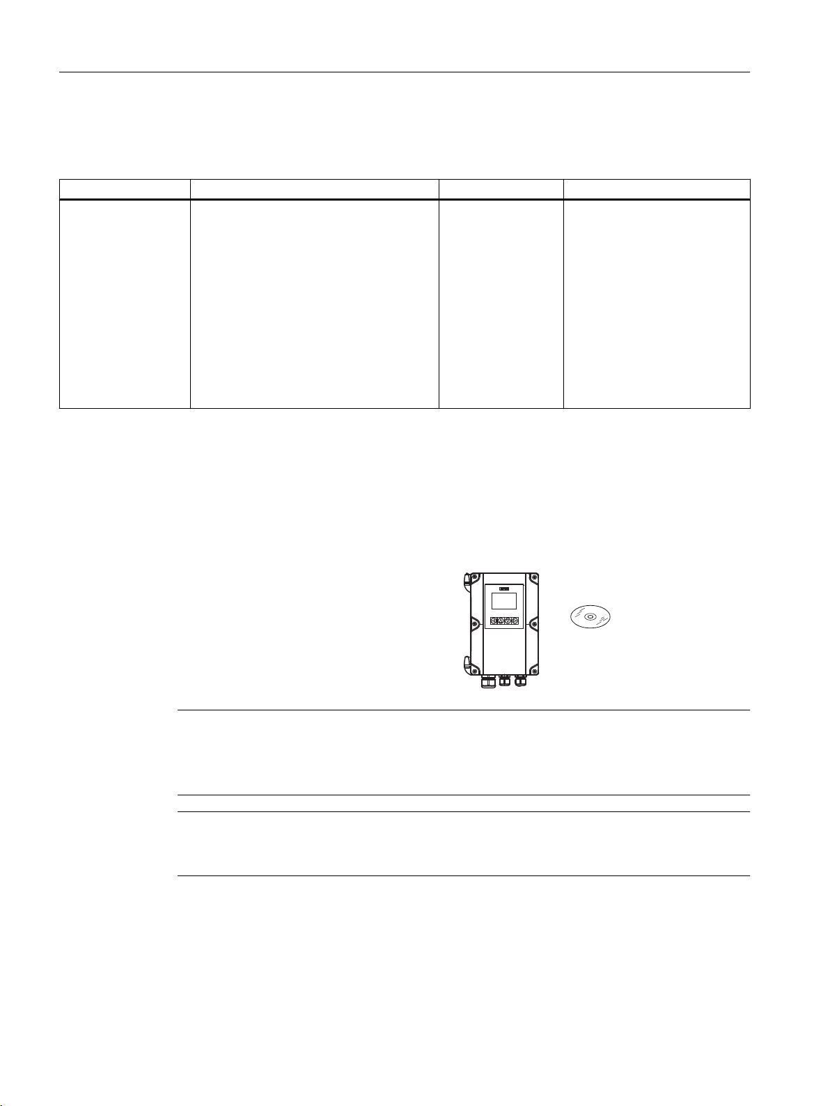
1.5 Items supplied
The device is delivered as:
Wall mount enclosure
● FST020 transmitter wall mount enclosure
● Siemens Process Instrumentation disk
containing certificates and manuals.
Note
Supplementary information
Supplementary product and production specific certificates are included on the SensorFlash®
SD card in the transmitter socket.
Note
Scope of delivery may vary, depending on version and add-ons. Make sure the scope of
delivery and the information on the nameplate correspond to your order and the delivery note.
FST020 IP65 NEMA 4X
10 Operating Instructions, 09/2017, A5E41425845-AB
Page 11

1.6 Checking the consignment
Check the device packaging for damage. Inform your supplier of any damage. Retain the
damaged parts for clarification.
Check the scope of delivery by comparing the shipping documents with your order for
correctness and completeness.
Do not take damaged or incomplete devices into operation under any circumstances.
Special conditions for storage and transportation of device listed in Section "Service and
maintenance (Page 57)".
Identification
Note
IMPORTANT
This device is NOT to be used in hazardous areas.
CE declaration is delivered with the device.
Introduction
1.7 Further Information
Transmitter model number is: FST020
The system ordering code represents the transmitter including accessories.
AC System ordering code: 7ME3570-1JA4XXXXXX
DC System ordering code: 7ME3570-1JB4XXXXXX
AC - Transmitter ordering code: 7ME3570 - 1JA40-0AA1
DC - Transmitter ordering code: 7ME3570 - 1JB40-0AA1
1.7 Further Information
Product information on the Internet
The Operating Instructions are available on the documentation disk shipped with the device,
and on the Internet on the Siemens homepage, where further information on the range of
SITRANS F flowmeters may also be found:
Product information on the internet (
Worldwide contact person
http://www.siemens.com/flow)
If you need more information or have particular problems not covered sufficiently by these
Operating Instructions, get in touch with your contact person. You can find contact information
for your local contact person on the Internet:
Local contact person (http://www.automation.siemens.com/partner)
FST020 IP65 NEMA 4X
Operating Instructions, 09/2017, A5E41425845-AB 11
Page 12

Introduction
1.8 Notes on warranty
See also
Technical support (Page 173)
1.8 Notes on warranty
The contents of this manual shall not become part of or modify any prior or existing agreement,
commitment or legal relationship. The sales contract contains all obligations on the part of
Siemens as well as the complete and solely applicable warranty conditions. Any statements
regarding device versions described in the manual do not create new warranties or modify the
existing warranty.
The content reflects the technical status at the time of publishing. Siemens reserves the right
to make technical changes in the course of further development.
FST020 IP65 NEMA 4X
12 Operating Instructions, 09/2017, A5E41425845-AB
Page 13

Safety notes
2.1 Precondition for use
This device left the factory in good working condition. In order to maintain this status and to
ensure safe operation of the device, observe these instructions and all the specifications
relevant to safety.
Observe the information and symbols on the device. Do not remove any information or symbols
from the device. Always keep the information and symbols in a completely legible state.
2.2 Warning symbols on the device
Symbol Explanation
Caution. The Caution symbol is used throughout the operating instructions.
2
2.3 Laws and directives
Observe the safety rules, provisions and laws applicable in your country during connection,
assembly and operation. These include, for example:
● National Electrical Code (NEC - NFPA 70) (USA)
● Canadian Electrical Code (CEC) (Canada)
For CE marked equipment the device complies with the following directives:
● Low voltage directive LVD 2014/35/EU
● EMC directive 2014/35/EU
● Restriction of hazardous substances directive 2011/65/EC and 2015/863/EU
FST020 IP65 NEMA 4X
Operating Instructions, 09/2017, A5E41425845-AB 13
Page 14

Safety notes
2.5 Lithium batteries
2.4 Conformity with European directives
The CE marking on the device symbolizes the conformity with the following European
directives:
Electromagnetic compatibili‐
ty EMC
2014/30/EU
Low voltage directive LVD
2014/35/EU
Restrictions on Hazardous
Substances
RoHS 2011/65/EC and
2015/863/EU
The applicable directives can be found in the EU declaration of conformity of the specific device.
2.5 Lithium batteries
Lithium batteries are primary power sources with high energy content designed to represent
the highest possible degree of safety.
WARNING
Lithium batteries
Explosion Hazard - Can cause death or serious injury.
Directive of the European Parliament and of the Council on the
harmonisation of the laws of the Member States relating to elec‐
tromagnetic compatibility
Directive of the European Parliament and of the Council on the
harmonisation of the laws of the Member States relating to the
making available on the market of electrical equipment designed
for use within certain voltage limits
EU Directive: Restriction of Hazardous Substances in Electrical
and Electronic Equipment Directive and Annex II Commission
Delegated Directive
Lithium batteries may present an Explosion Hazard if they are abused electrically or
mechanically. This is in most circumstances associated with the generation of excessive heat
where internal pressure may cause the cell to rupture.
Thus the following basic precautions should be observed when handling and using lithium
batteries:
● Do not short-circuit, recharge or connect with false polarity.
● Do not expose to temperature beyond the specified temperature range or incinerate the
battery.
● Do not crush, puncture or open cells or disassemble battery packs.
● Do not weld or solder to the battery’s body.
● Do not expose contents to water.
FST020 IP65 NEMA 4X
14 Operating Instructions, 09/2017, A5E41425845-AB
Page 15
Description
'&32:(5
3.1 Overview
SITRANS FST020 ultrasonic flow meter systems consist of a transmitter and a sensor. The
following table lists the available combinations of transmitters and sensors.
Transmitter Sensor type
FST020 FSS200 family
3.2 Design
The transmitter reads the measured process values from the sensor and calculates derived
values. It provides Modbus communications, 1x 4-20ma, 1x relay, and 1x Pulse/Frequency,
USB service port, and a local display. It also adds functionalities such as totalizers, access
control, diagnostics, and configuration. The local user interface consists of a display and four
buttons for user interaction.
The transmitter has a modular design with discrete, replaceable electronic modules and
connection boards to maintain separation between functions and facilitate field service. All
modules are fully traceable and their provenance is included in the transmitter setup.
3
DN 15 to DN 10m (0.5" to 360")
The SITRANS FST020 is available as:
Wall mount housings: AC and DC
Figure 3-1 DC Wall Mount housing shown
FST020 IP65 NEMA 4X
Operating Instructions, 09/2017, A5E41425845-AB 15
Page 16
Description
3.3 Features
Pipe mount kit
The Pipe kit is CQO:1012NMB-1.
Figure 3-2 Pipe Mounting shown with mounting plate
3.3 Features
● Wall mount IP65 enclosure
● Full graphical local display
● SensorFlash (SD card) for memory backup, Datalogger and documentation storage
(certificates etc.)
● USB service interface
● Modbus communications
● One pulse/frequency output
● One relay
● One current output 4-20 mA
● High immunity against process noise
● Fast response to step changes in flow
● High update rate (100 Hz) on all process values
FST020 IP65 NEMA 4X
16 Operating Instructions, 09/2017, A5E41425845-AB
Page 17

Description
3.3 Features
● Measurement of:
– Volume flow
– Mass flow (with fixed density setpoint)
– Flow velocity
– Sound velocity
● Configurable upper and lower alarms and warning limits for nearly all process values
● Independent low flow cut-off settings for volume flow and mass flow
● Zero-point adjustment (initiated by host system)
● Process noise damping using digital signal processing (DSP)
● Simulation of process values
● Simulation of all outputs
● Simulation of alarms
● Enabling alarms for visibility on all outputs (HMI, status and communication)
● Comprehensive diagnostics (Siemens standard) for troubleshooting and sensor checking
● Firmware update
● Data logging in SensorFlash
● Peak indicators
● Alarm delay
FST020 IP65 NEMA 4X
Operating Instructions, 09/2017, A5E41425845-AB 17
Page 18

Description
3.3 Features
FST020 IP65 NEMA 4X
18 Operating Instructions, 09/2017, A5E41425845-AB
Page 19
Installing/mounting
4.1 Chapter overview (transmitter)
This chapter describes how to install the wall mount housing transmitter.
Wall mount housing
The wall mount housing transmitter can be mounted either on a wall or on a pipe (with optional
pipe mount bracket), see Installation instructions (Page 20).
4.2 Installation location requirements
4.2.1 Environment
SITRANS F flowmeters with minimum IP65/NEMA 4X enclosure rating are suitable for indoor
and outdoor installations.
Process pressure and medium temperature
If applicable, make sure that specifications for rated medium temperature (TS) plus ambient
temperature that are indicated on the device nameplate / label will not be exceeded.
4
Aggressive atmospheres
Ensure that the device is suitable for the application and that it is installed where there is no
risk of penetration of aggressive vapors.
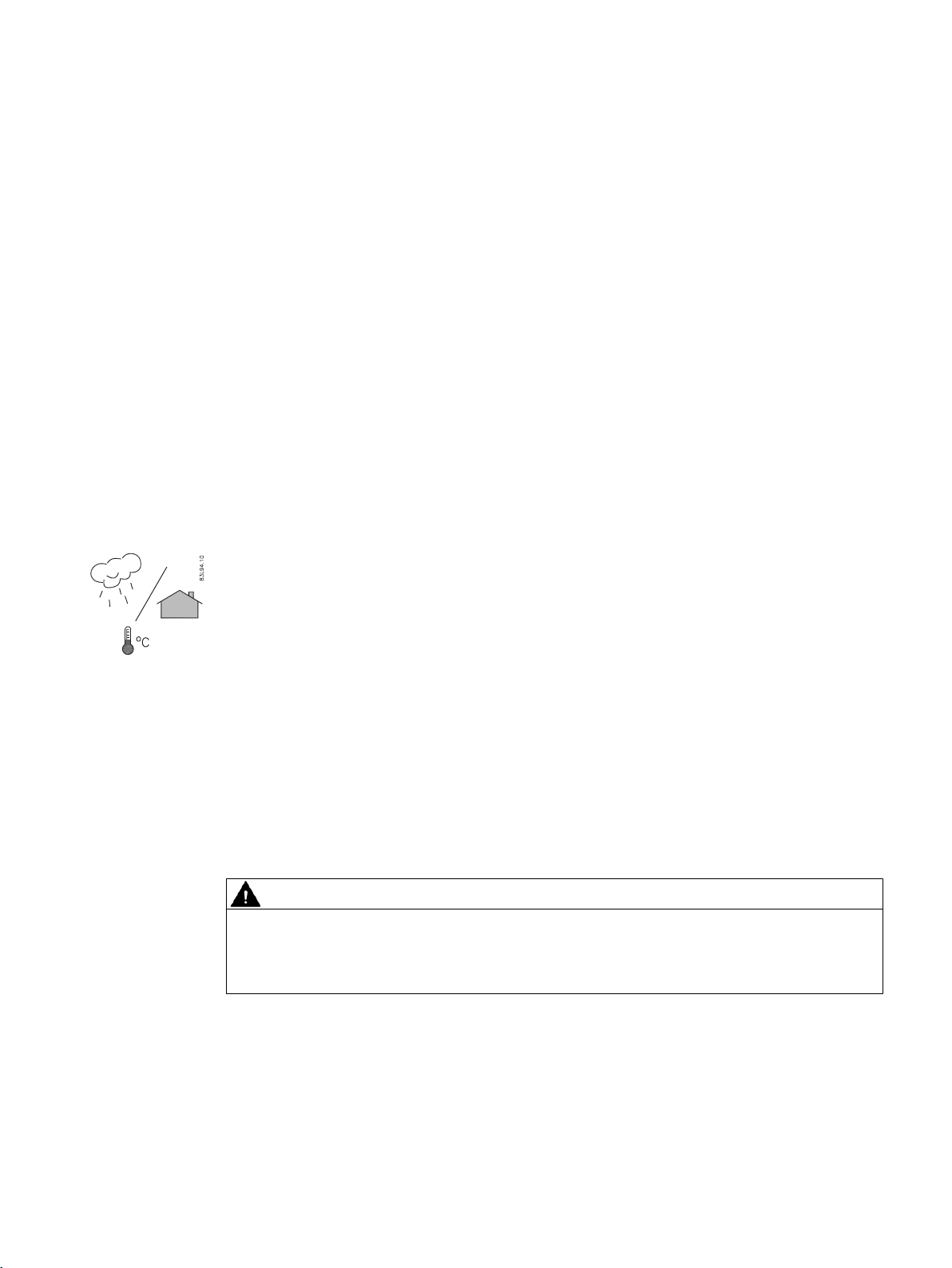
Direct sunlight
Prevent the device from overheating or materials becoming brittle due to UV exposure by
protecting it from direct sunlight. Make sure that the maximum permissible ambient
temperature is not exceeded. Refer to the information in Technical data (Page 65).
WARNING
Electrical shock hazard
May cause death or serious injury
Disconnect power before working on this product.
Upstream / Downstream
Avoid long drop lines downstream from the sensor to prevent the meter pipe from draining.
Avoid installing the sensor upstream of a free discharge in a drop line where possible.
FST020 IP65 NEMA 4X
Operating Instructions, 09/2017, A5E41425845-AB 19
Page 20

Installing/mounting
4.3 Installation instructions
Sensor Location in piping system
The optimum location in the system depends on the presence of excessive gas or air bubbles
in the fluid may result in erroneous measurements. Therefore, it is preferred not to install the
sensor at the highest point in the system, where gas / air bubbles will be trapped. For liquids
it is advantageous to install the sensor in low pipeline sections, at the bottom of a U-section
in the pipeline.
4.2.2 Normal environmental conditions
Normal environmental conditions
This standard applies to equipment designed to be safe at least under the following conditions:
● Indoor and outdoor use
● Altitude up to 2000 m
● Operating temperature -10 °C to 50 °C (14 °F to 122 °F)
● Maximum relative humidity 80 % for temperatures up to 31 °C decreasing linearly to 50 %
relative humidity at 40 °C (104 °F)
● Mains supply voltage fluctuations up to ±10 % of the nominal voltage
● Transient Overvoltages up to the levels of Overvoltage Category II
● Temporary Overvoltages occurring on the Mains supply.
● Pollution Degree II
4.3 Installation instructions
4.3.1 Wall mount transmitter
Wall mounting
WARNING
Hazardous voltage
May cause death or serious injury
Disconnect power before working on this device.
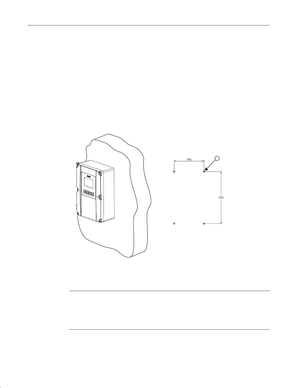
The transmitter can be mounted on any wall surface including wood, metal or concrete. Use
the appropriate bolts and screws as needed for your mounting application and adhere to local
codes.
FST020 IP65 NEMA 4X
20 Operating Instructions, 09/2017, A5E41425845-AB
Page 21
PP
PP
Installing/mounting
4.3 Installation instructions
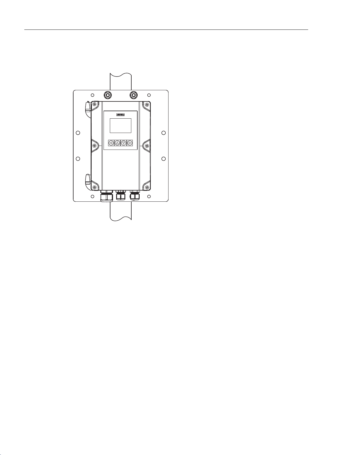
Prepare holes for the four screws (M6x100 or equivalent). Screw head diameter: max. 13.5
mm; screw shaft diameter: max. 6 mm.
● Recommended mounting: Directly to wall or to electrical cabinet back panel.
● If alternate mounting surface is used it MUST support four times the weight of the unit.
Mounting the enclosure
1. Loosen the enclosure cover screws and open the cover to reveal the mounting holes.
2. Mark and drill four holes in the mounting surface for four mounting screws (supplied).
3. Using a long flat-blade screw driver, mount transmitter and tighten screws.
4. Tighten nuts (torque: 10 Nm).
5. Refer to Connecting the power supply (Page 28) and Sensor connections (Page 28) to
complete installation.
Figure 4-1 Wall mounted transmitter showing mounting hole pattern
Mounting on pipe
Note
Mounting on pipe
For mounting on pipe, see the installation instructions given in the CQO:1012NMB-1
instructions that are provided with the optional mounting bracket kit.
U-bolts and other miscellaneous hardware are not supplied with the flowmeter.
FST020 IP65 NEMA 4X
Operating Instructions, 09/2017, A5E41425845-AB 21
Page 22

Installing/mounting
4.3 Installation instructions
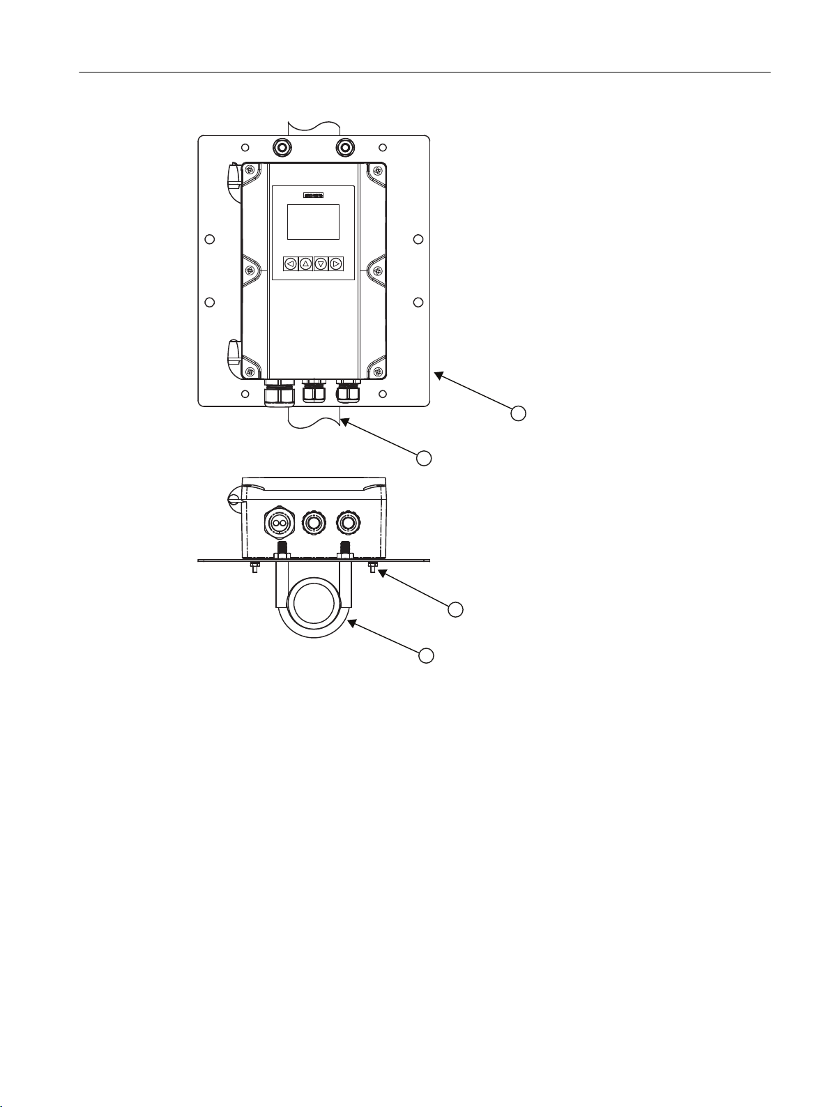
For installation on 2-inch standpipe use the optional CQO:1012NMB pipe mounting kit.
Table 4-1 CQO:1012NMB-1 Mounting Kit
Description Qty
Mounting Plate 1
U-Bolt Assembly including bracket and nuts 2
8-32 x 5/8 LG cross round head screws 4
#8 Flat washer 4
#8 Split lock washers 4
8-32 Hex nut 4
1. Affix mounting plate to standpipe using the U-bolt assemblies.
2. Secure transmitter to mounting plate using #8-32 screws, washers and nuts.
3. Tighten nuts (torque: 10 Nm).
4. Refer to Connecting the power supply (Page 28) and Sensor connections (Page 28) to
complete installation.
Note
Use conduit fittings or cable glands on all cables.
FST020 IP65 NEMA 4X
22 Operating Instructions, 09/2017, A5E41425845-AB
Page 23
Installing/mounting
4.3 Installation instructions
① Mounting plate
② Stand pipe
③ Mounting hardware (see table above)
④ U-bolt assembly
FST020 IP65 NEMA 4X
Operating Instructions, 09/2017, A5E41425845-AB 23
Page 24

Installing/mounting
4.3 Installation instructions
FST020 IP65 NEMA 4X
24 Operating Instructions, 09/2017, A5E41425845-AB
Page 25

Connecting
This chapter describes how to wire up the transmitter for operation with a sensor.
● Transmitter power supply, communications and I/O connections (Page 28)
● Sensor connections (Page 28)
● Connecting the power supply (Page 28)
● Connecting Inputs/Outputs (Page 30)
● Connecting channel 1 (Page 31) (Modbus communication channel)
For connection of the sensor, see the relevant sensor Installation Manual.
5.1 Basic safety notes
5.1.1 Missing PE/ground connection
5
WARNING
Missing PE/ground connection
Risk of electric shock. May cause death or serious injury.
Depending on the device version, connect the power supply as follows:
● Power plug: Ensure that the used socket has a PE/ground conductor connection. Check
that the PE/ground conductor connection of the socket and power plug match each other.
● Connecting terminals: Connect the terminals according to the terminal connection
diagram. First connect the PE/ground conductor.
5.1.2 Energized devices
WARNING
Energized devices
Risk of electric shock. May cause death or serious injury.
When energized the device may be opened by qualified personnel only.
FST020 IP65 NEMA 4X
Operating Instructions, 09/2017, A5E41425845-AB 25
Page 26

Connecting
5.3 Device nameplates
WARNING
Mains supply from building installation overvoltage category 2
A circuit breaker (max. 15 A) must be installed in close proximity to the equipment and within
easy reach of the operator. It must be marked as the disconnecting device for the equipment.
WARNING
DC connection devices
The DC power source must be isolated from mains supply.
5.2 Disconnecting device
Overvoltage Category II
Connect mains supply through a circuit breaker (max. 15 A) in close proximity to the transmitter
and within easy reach of the operator. Mark it as the disconnecting device for the transmitter.
5.3 Device nameplates
Each part of the system has one nameplate type showing the following information:
● product identification
● product specifications
● certificates and approvals
Note
Identification
Identify your device by comparing your ordering data with the information on the product
and specification nameplates.
The transmitter is identified as "Ultrasonic transmitter SITRANS FST020" and the sensor as
"Ultrasonic sensor SITRANS FSS200".
FST020 IP65 NEMA 4X
26 Operating Instructions, 09/2017, A5E41425845-AB
Page 27
5.3.1 Device nameplate
$&'&
Transmitter nameplates
Connecting
5.3 Device nameplates
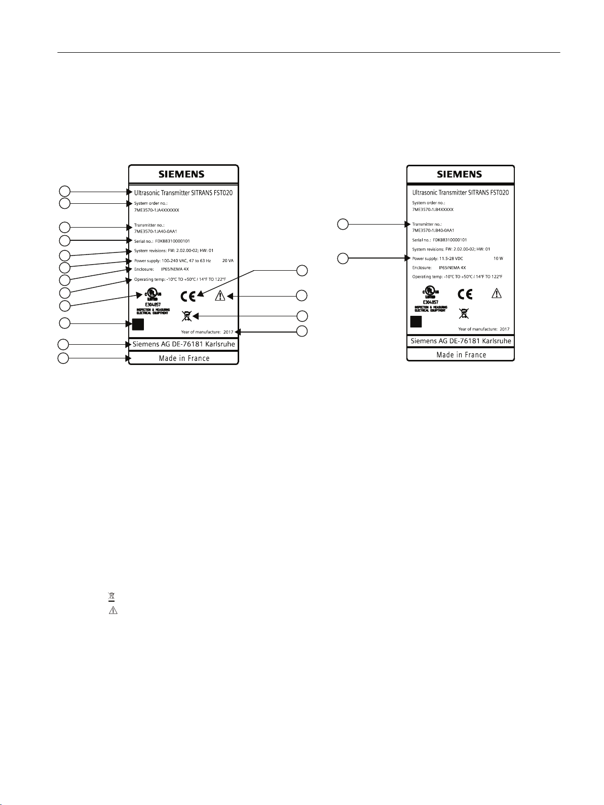
① Product name Transmitter product name
② System order no. Device-specific system order number (transmitter and sensor)
③ Transmitter order no. Transmitter replacement order numbers
④ Serial no. Transmitter serial number
⑤ System revisions System revision numbers; firmware (FW) and hardware (HW)
⑥ Power Supply Power supplies: AC and DC
⑦ Enclosure IP Degree of protection
⑧ Operating temperature Operating temperature of the device
⑨ Agency marking Specific agency identification marking
⑩ Data matrix code Product-specific QR-code
⑪ Contact information ad‐
dress
Contact address for device information
⑫ Place of manufacture Device place of manufacture
⑬ Year of Manufacture Manufacturing year. More detailed manufacturing date information is given in the serial
number (see sensor identification nameplate above)
⑭ WEEE symbol, see Disposal (Page 59)
⑮ Caution symbol
⑯ CE CE mark
Figure 5-1 Transmitter Labels: AC-DC
FST020 IP65 NEMA 4X
Operating Instructions, 09/2017, A5E41425845-AB 27
Page 28
Connecting
5.4 Transmitter power supply, communications and I/O connections
5.4 Transmitter power supply, communications and I/O connections
5.4.1 Sensor connections
For sensor connection, see the FSS200 Sensor installation instructions manual.
5.4.2 Connecting the power supply
Note
If the transmitter is not already mounted and cabling has not been run, proceed to Mounting
the Transmitter (Page 20) before connecting power.
WARNING
Hazardous Voltage
May cause death or serious personal injury.
Disconnect power before working on this product.
1. Using a flat-head screwdriver, loosen the six securing screws from the Keypad Enclosure
Cover and open cover.
2. To determine type of power connection refer to the following part numbers:
– 7ME3570-1HA4 = AC Power (with 500mA fuse)
– 7ME3570-1HB4 = DC Power (with 2A fuse)
3. Remove input power blind plug and fit cable gland.
4. Push cable through open gland and cable path.
5. Loosen power plug connector screws.
6. Referring to the illustration and table below, as per local electric codes, wire input power
connector for AC or DC power depending on power supply provided.
Connector pins AC DC Wire color
1 L1 + Black
2 L2N - White
3 Ground Ground Green
FST020 IP65 NEMA 4X
28 Operating Instructions, 09/2017, A5E41425845-AB
Page 29

11.5-28VD C
$&
'&
Connecting
5.4 Transmitter power supply, communications and I/O connections
7. Insert AC or DC power wires into wire entry holes and secure by tightening wire clamp
screws using a screwdriver.
– For AC - Connect ground to terminal and power to terminals L1 and L2N.
– For DC - Connect ground to terminal and power to terminals + and -.
Note
Power supply connector wires should be stripped stranded or solid conductors AWG 12-18.
① Power input (AC or DC - see inserts) ⑥ Relay
② I/O terminals TB1 ⑦ 4-20 mA
③ Modbus ⑧ I/O input cable - 30m (98ft) max length
④ Totalizer ⑨ Power input cable
⑤ Pulse ⑩ Sensor cables - 90m (300 ft) max length
Figure 5-2 Input Power Wiring
8. Plug power connector into jack.
FST020 IP65 NEMA 4X
Operating Instructions, 09/2017, A5E41425845-AB 29
Page 30
$&
'&
Connecting
5.4 Transmitter power supply, communications and I/O connections
9. Tighten cable gland.
10.Connect the power cable to the appropriate power source (100-240 VAC @ 50/60 Hz or
11.5-28.5 VDC) and power up unit.
WARNING
Circuit limited to 15 Amps
The branch circuit must be limited to 15A or damage to the unit and death or serious injury
may result.
It is recommended that the circuit breaker be located near the transmitter.
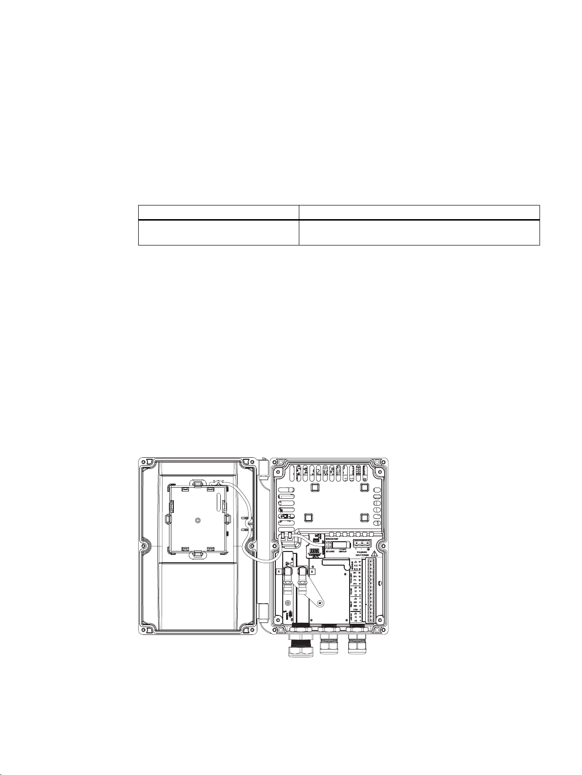
5.4.3 Connecting Inputs/Outputs
1. Remove blind plugs where required from the flowmeter case.
2. Loosen spring screws on housing lid.
3. Open housing lid.
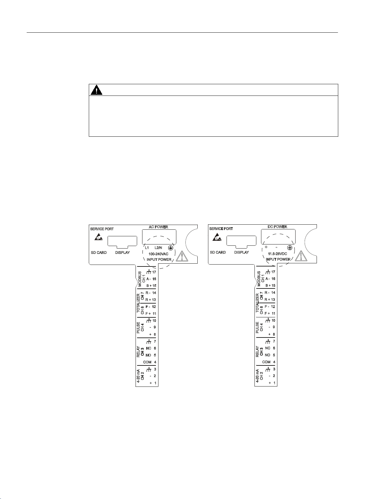
A label showing the device configuration is placed on the PC board inside the transmitter
housing. It is either for AC or DC power depending on the flowmeter type.
Figure 5-3 Inside cover - AC and DC labels
FST020 IP65 NEMA 4X
30 Operating Instructions, 09/2017, A5E41425845-AB
Page 31

5.4.4 Connection Wiring
Terminal Block Wiring
These connection diagrams apply to the part numbers listed below.
FST020 7ME3570..._...
Figure 5-4 Terminal board channels and pin numbers
Note
4 to 20 mA current output Channel 2
Connecting
5.4 Transmitter power supply, communications and I/O connections
SITRANS FST020
It is not required to use shielded cables for the pure 4 to 20 mA current output.
Table 5-1 Input/Output Wiring
Pin# Signal Function Description
1 Io1+ Isolated Loop Supply Spannable 4-20mA output (Loop Powered) This
2 Io1- Isolated Loop Return
3 Chassis Ground Ground
4 C Common Relay Output
5 NO Normally Open Relay Output
6 NC Normally Closed Relay Output
7 Chassis Ground Ground
8 PULSE OUTPUT + Isolated Transistor Menu selection: PGEN, POS TOTAL, NEG TO‐
9 PULSE OUTPUT - Isolated Transistor
10 Chassis Ground Ground
11 NO TOT + DIGITAL INPUT + Stops Totalizer from incrementing.
12 NO TOT - DIGITAL INPUT 13 CLR TOT + DIGITAL INPUT + Clears Totalizer
14 CLR TOT - DIGITAL INPUT 15 Modbus_B Differential + Serial communication, Modbus protocol
16 Modbus _A Differential - Serial communication, Modbus protocol
17 Chassis Ground Ground
output also provides a fault indication by drop‐
ping to 2mA if assigned to flow rate and under
fault conditions.
TAL
FST020 IP65 NEMA 4X
Operating Instructions, 09/2017, A5E41425845-AB 31
Page 32

9
F
9
F
9
F
WRΩ
9
F
5
/
5
/
5
/
5
/
&
12
1&
,
21
PD[
P$
,
21
PLQ
PD[
P$
,
21
PLQ
PD[
P$
,21
PD[
P$
9
R
Ω
Ω
9'&
PD[
9'&
PD[
ื5/ื.വ
9
F
PD[ 9∗5
/
9& 9'&PD[
5
/
.PLQ
ื9
F
ื 9
%
$
9
FF
9
9
,+
9PLQ
9
,/
9PD[
9
LQ
PD[9WR9
5
/
9
F
Connecting
5.4 Transmitter power supply, communications and I/O connections
Wiring
① 4 - 20mA output (current source) ④ Digital input (Freeze TOT)
② Relay output ⑤ Digital input (CLR TOT)
③ Pulse output ⑥ Modbus
Isolated 4-20mA Output TB1-1/2
R = 250 Ω typical, 750 Ω maximum
Vc = 24 VDC typical / 30 VDC maximum
I = 4-20mA
RL = Loop wire resistance (both ways) plus User's input load resistance.
Figure 5-5 Typical FST020 Wiring
32 Operating Instructions, 09/2017, A5E41425845-AB
FST020 IP65 NEMA 4X
Page 33

5.4 Transmitter power supply, communications and I/O connections
Pulse output TB1-8 / TB1-9
V
= +30 VDC max.
c
RL = 3K Ω minimum
Digital Inputs TB1-11 / TB1-12 and TB1-13 / TB1-14
Vc = (10V + 0.02 x RL) max. 2 ≤ Vc ≤ 30 VDC
0 ≤ RL ≤ 1000 Ω
See also
Connecting Inputs/Outputs (Page 30)
5.4.5 Finishing the transmitter connection (wall mount housing)
Connecting
Connection check-up
1. Check individual wire and cable installations by tugging firmly.
2. Firmly tighten cable glands and insert blanking plugs in unused cable entries.
3. Close flowmeter cover.
4. Tighten the six cover securing spring screws.
Your device is now ready for commissioning.
FST020 IP65 NEMA 4X
Operating Instructions, 09/2017, A5E41425845-AB 33
Page 34

Connecting
5.4 Transmitter power supply, communications and I/O connections
FST020 IP65 NEMA 4X
34 Operating Instructions, 09/2017, A5E41425845-AB
Page 35

Commissioning
This chapter gives instructions to commissioning your device, see Commissioning via local
display (Page 37).
Furthermore, the device can be commissioned using SIMATIC PDM, see Commissioning with
PDM (Page 175).
6.1 Basic Safety notes
CAUTION
Loss of type of protection
Damage to device if the enclosure is open or not properly closed. The type of protection
specified on the nameplate or in Technical data (Page 65) is no longer guaranteed.
● Make sure that the device is securely closed.
WARNING
6
Hot surfaces
Risk of burns resulting from hot surfaces.
● Take corresponding protective measures, for example by wearing protective gloves.
6.1.1 Hazardous contact voltage
WARNING
Hazardous contact voltage
May cause death or serious injury.
Risk of injury through hazardous contact voltage when the device is open or not completely
closed.
The degree of protection specified on the nameplate or in Technical data (Page 65)is no
longer guaranteed if the device is open or not properly closed.
● Make sure that the device is securely closed.
FST020 IP65 NEMA 4X
Operating Instructions, 09/2017, A5E41425845-AB 35
Page 36

Commissioning
6.5 Initial startup
6.2 General requirements
Before commissioning it must be checked that:
● The device has been installed and connected in accordance with the guidelines provided
in Installing/mounting (Page 19) and Connecting (Page 25).
6.3 Power-up
Power up the device. Local display will show a screen for initial startup (Page 36).
6.4 Local display
The device is commissioned/operated with the touch keypad on the local display.
The graphic display above the keypad gives a menu-guided operation of the individual device
function/parameters. Successful operation of the key is confirmed by tactile feedback as key
is pressed.
① Full graphical display
② Touch keypad
Figure 6-1 Local display
Note
HMI timeout
If no key is pressed for 10 minutes, the display switches to show operation view. If Backlight
is set to Automatic, display backlight goes off automatically 30 seconds after the last key press.
6.5 Initial startup
The first time the device is powered up, you will be prompted to set the language. The device
always starts up showing "Language" in English. When the language has been set, you will
be prompted to set the date and time.
Before using the flow meter for the first time, essential parameters should be considered. After
confirming/changing date and time you can choose to accept the default values or start the
Quick commissioning wizard.
FST020 IP65 NEMA 4X
36 Operating Instructions, 09/2017, A5E41425845-AB
Page 37

Start
Language
Quick commissioning
Set date and time
No
Yes
Continue with Quick commissioning wizard
First startup wizard is now finished
Welcome
Commissioning
6.6 Commissioning via local display
You will be asked if you want to start the "Quick commissioning" wizard. If you choose "Yes"
(recommended), the "Quick commissioning" wizard will start. If you choose "No", you accept
the default values of the device, and the next HMI view will be the operation view 1.
6.6 Commissioning via local display
6.6.1 Chapter overview
Text Options/description
Language Set the language: English, Deutsch
Welcome Information about the "Quick commissioning" wizard
Set date and time The set date and time (real time clock) is used for all time stamps of logged
information.
Quick commissioning The "Quick commissioning" wizard comprises the most important param‐
eters/menus for quick configuration of the flowmeter.
In this chapter it is described how to commission the device via the local display using the
Quick commissioning wizard.
FST020 IP65 NEMA 4X
Operating Instructions, 09/2017, A5E41425845-AB 37
Page 38

Start
Quick start
Quick commissioning
Sensor settings
Process values
Inputs and outputs
Copy configuration
Identification
Long tag
Location
Installation date
Next
Finished
Sensor settings
Process values
Inputs and outputs
Communication
Next
Basic configuration
Commissioning
6.6 Commissioning via local display
6.6.2 Wizards
6.6.2.1 Quick Commissioning wizard (menu item 1.1)
The Quick commissioning wizard will guide you through configuration of parameters essential
for your application. You configure parameters essential for your application by selecting the
configuration path and sub-wizards appropriate for your application.
6.6.2.2 Quick Commissioning wizard (wizard)
6.6.2.3 Sensor settings wizard (menu item 1.2)
38 Operating Instructions, 09/2017, A5E41425845-AB
Text Options/Description
Select a basic configura‐
tion wizard
Set the identification pa‐
rameters
Sensor settings, Process values, Inputs and outputs, Copy configuration
Long tag, Location, Installation date
The "Quick commissioning" wizard comprises the following subwizards:
● Sensor settings wizard (wizard) (Page 39)
● Process values wizard (wizard) (Page 44)
● Inputs/Outputs wizard (Page 45)
Each sub-wizard has its own view numbering. The sub-wizard name and the parameter name
are shown in the upper left corner of the display. The view number and the total views in the
sub-wizard are shown in the upper right corner of the display.
The Sensor settings wizard will guide you through configuration of essential parameters.
FST020 IP65 NEMA 4X
Page 39

6.6.2.4 Sensor settings wizard (wizard)
Pipe settings
Units settings
Sensor settings (1)
Yes
No
Units settings
Text Options/Description
Unit settings Select "Yes" to configure the display units.
Unit settings Set the display units of length, temperature, pressure, kinematic viscosity,
and density.
Commissioning
6.6 Commissioning via local display
FST020 IP65 NEMA 4X
Operating Instructions, 09/2017, A5E41425845-AB 39
Page 40

Pipe settings
Sensor settings (2)
Pipe class
Sensor settings
Pipe size
Outer diameter + wall thic kness
Circumference + wall thickness
Outer pipe diameter
Wall thickness
Custom
Custom
Liner
Wall sound velocity
Yes
No
Liner material
Liner settings
Yes
No
Pipe circumference
Inner pipe roughness
1)
Select material
Disturbed flow
Commissioning
6.6 Commissioning via local display
Text Options/Description
Pipe settings Select "Yes" to configure the pipe.
Pipe class Select the pipe class.
Pipe size Select the pips size from the options available for the selected pipe class.
Pipe circumference Enter pipe circumference. Only available if custom pipe class is selected.
Outer pipe diameter Enter outer pipe diameter. Only available if custom pipe class is selected.
Wall thickness Enter wall thickness. Only available if custom pipe class is selected.
Select material Select the pipe material.
Wall sound velocity Enter the wall sound velocity of the material. Only available if custom
material is selected.
40 Operating Instructions, 09/2017, A5E41425845-AB
FST020 IP65 NEMA 4X
Page 41

Medium settings
Yes
Sensor t ype
FSS200 high precision
FSS200 / 1011 universal
FSS200 / 991 high temperature
1011 high precision liquid
Sensor size
Sensor selection
Sensor settings
Sensor setting (3)
No
Sensor size
Commissioning
6.6 Commissioning via local display
Liner Select "Yes" to configure the liner material.
Select "No" to only configure the Inner pipe roughness.
Liner material Select the liner material.
Liner settings Set the liner sound velocity and thickness.
Disturbed flow Define the type of pipe configuration and the distance to the sensor.
Inner pipe roughness Set the inner pipe roughness.
* Select "Custom" to enter non-standard values.
FST020 IP65 NEMA 4X
Operating Instructions, 09/2017, A5E41425845-AB 41
Text Options/Description
Sensor settings Select "Yes" to configure the sensors.
Sensor settings Select the sensor type installed (found on sensor label).
Sensor size Select the sensor size from the options list (found on sensor label).
Sensor selection Define the temperature compensation mode, the temperature class, the
spacing offset and the cable length
Page 42

Medium settings
Path settings
No
Process parameters
Sensor settings (4)
Yes
Medium settings
Custom
Commissioning
6.6 Commissioning via local display
Text Options/Description
Medium settings Select "Yes" to configure the medium.
Medium settings Select the process medium.
Process parameters Set the expected sound velocity (only available if custom process medium
is selected) and the process temperature, pressure, kinetic viscosity, and
density.
42 Operating Instructions, 09/2017, A5E41425845-AB
FST020 IP65 NEMA 4X
Page 43

Sensor settings (5)
Path settings
No
Yes
Installed paths
Save settings
Start measurement
Mounting path 1
Path 1
Path geometr y
*
**
Finished
Commissioning
6.6 Commissioning via local display
6.6.2.5 Process Values wizard (menu item 1.3)
Text Options/Description
Path settings Select "YES" to configure the path(s).
Installed paths Select the paths installed.
Save settings Moves to the next menu item.
Start measurement * for each installed path. Select the path to configure.
Path geometry Define the geometry of the path (direct or reflect mode)
Mounting path 1 Represents the spacing offset. Use Nom for most applications.
Path 1 Select "Receiver signal" to view graphical display of the receiver signal.
The Process values wizard will guide you through setup of process values for your application.
The prioritizing of the process values automatically configures the measurement views on the
display. The process value configured as first process value is set as first display view.
** Select "Next" to configure next path or to select "Next" to finish the
wizard.
FST020 IP65 NEMA 4X
Operating Instructions, 09/2017, A5E41425845-AB 43
Page 44

1
2
3
Star t
Prioritize
1st process value
2st process value
3st process value
4st process value
5st process value
6st process value
Next
Quick start
Quick commissioning
Sensor settings
Process values
Inputs and outputs
Copy configuration
Totalizers
Totalizer
Totalizer
Process value
Mass flow
Volume flow
Standard volume flow*
Yes
No
Process value
Units
Direction
Fail-safe behavior
Next
Fail-safe behavior
Run
Hold
Memory
1st value
Volume flow
Mass flow
Flow velocity
Sound velocity
Density
Kinematic viscosity
Totalizer
Medium temperature
Units
process value
specific list
Finished
Units
Process value
specific list
Direction
Forward and backward
Forward
Backward
Hold
Activate totalizer view
Units
process value
specific list
Low flow cut-off
Next
Commissioning
6.6 Commissioning via local display
① Wizard name
② Step name / Parameter name
③ View number / Total views in wizard
6.6.2.6 Process values wizard (wizard)
44 Operating Instructions, 09/2017, A5E41425845-AB
FST020 IP65 NEMA 4X
Page 45

6.6.2.7 Inputs/Outputs wizard
The first screen in the Inputs and outputs wizard informs about the active/passive operation
availability. It shows the application possibilities of your hardware. The kind of operation
depends on the wiring.
The Inputs and outputs wizard will guide you through setup of inputs and outputs on the
available channels.
Channel 2 - output
Channel 3 - relay
Channel 4 -input/output
6.6.3 Navigating the menu structure
6.6.3.1 Chapter overview
Commissioning
6.6 Commissioning via local display
In this chapter it is described how to commission the device via the local display using the
Quick commissioning wizard.
6.6.3.2 Navigation view
The exact structure of the operating menu is explained in the Function Manual.
All items of the menu structure of the device are identified with a unique number.
Level 1 of the menu structure is standardized for all Siemens Process Instrumentation devices
and covers the following groups:
1. Quick start: Lists the most important parameters for quick configuration of the device. All
parameters in this view can be found elsewhere in the menu.
2. Setup: Contains all parameters which are needed to configure the device.
3. Maintenance and diagnostics: Contains parameters which affect the product behavior
regarding maintenance, diagnostics and service.
4. Communication: Contains parameters which describe the Modbus communication settings
of the device.
FST020 IP65 NEMA 4X
Operating Instructions, 09/2017, A5E41425845-AB 45
Page 46

1
2
3
4
5
Commissioning
6.6 Commissioning via local display
5. Security: Contains parameters which describe all security settings of the device.
6. Language: Parameter for changing the language of the local display. Regardless of the
language setting, the term for this parameter is always the English term (Language).
① List of menu structure items
② Name of the previously selected item
③ Number of highlighted item
④ Alarm status text
⑤ Device status icon
Figure 6-2 Level 1 of the menu structure
6.6.3.3 Navigating the menu structure
You can navigate through the menu structure items in the device using the four buttons on the
display as described below.
Table 6-1 Key functions - menu structure navigation
Key Function
Return to previous item.
Select the item above.
Select the item below.
Enter the selected item.
46 Operating Instructions, 09/2017, A5E41425845-AB
FST020 IP65 NEMA 4X
Page 47

Operating
These Operating Instructions describe the operation via the local display (HMI). The device
can also be operated via various software.
7.1 Display views
There are six display views, all fully configurable. Use the and the keys to switch between
the operator views,
Four different types of views are available:
● Display of measured process values, see Reading the process values (Page 49).
● Display for totalizer operation, see Operating the totalizer (Page 51).
● Display of a list of active alarms, see Handling alarms (Page 52).
● Display of six configurable measurement/diagnostic values, see AUTOHOTSPOT.
7.2 Access control
7
You can view all items in the HMI menu but the parameters are protected against changes
through access level control. To gain access, select one of the following access levels:
● Read only
Allows no configuration. The parameter values can be viewed only (indicated by a
symbol). No PIN code required.
● User
Allows configuration and service of all parameters except calibration parameters. Default
PIN code is 2457.
● Expert
Allows configuration and service of all parameters including flow and calibration
parameters. Default PIN code is 2834.
FST020 IP65 NEMA 4X
Operating Instructions, 09/2017, A5E41425845-AB 47
Page 48

Operating
7.3 Operating the FST020
PIN codes can be changed in Security (5).
Note
Lost PIN code
If the PIN code is lost, provide Siemens customer support with the transmitter serial number
(see nameplate). Siemens customer support will provide a code to be entered in PIN
recovery (5.3).
Disable access level control
If logged in as Expert you can Deactivate user PIN. As User you will not be prompted to enter
the password. Enabling the access level control can be done in Activate user PIN and requires
entering the Expert password.
Auto logout function
You will not be prompted for password for 10 minutes after the last key press.
NOTICE
Device restart
Whenever the device is restarted, the access level is reset to Read only.
7.3 Operating the FST020
7.3.1 Fixed display texts
Some displayed texts are fixed, which means they will not change regardless of changed
display language.
The following tables list the fixed display texts and their corresponding process value,
diagnostic value, and compensation value names.
Table 7-1 Process values
Fixed display text Process value name
VOL.FLOW Volume flow
MASS FLOW Mass flow
FLOW VEL Flow velocity
SOUND VEL Sound velocity
DENSITY Density (Fixed value)
KIN. VISCOSITY Kinematic viscosity (Fixed value)
FST020 IP65 NEMA 4X
48 Operating Instructions, 09/2017, A5E41425845-AB
Page 49

Fixed display text Process value name
FLUID TEMP. Medium temperature (Fixed value
TOT1 Totalizer 1
Table 7-2 Diagnostic values
Fixed display text Diagnostic value name
TRN TEMP. Transmitter internal temperature
CURR. OUT (CH2) Ch2 value
REYNOLDS NO. Reynolds number
P1.SNR UP SNR up path 1
P1.SNR DOWN SNR down path 1
P1.SOUND VEL Sound velocity path 1
P1.DELTA TIME Delta time path 1
P1.ACC.BURST Path 1 percentage of bursts accepted
P1.PEAK AMP.DN Peak amplitude down path 1
P1.PEAK AMP.UP Peak amplitude up path 1
Operating
7.3 Operating the FST020
7.3.2 Reading the process values
The value of the process values can be displayed either as one or more numeric values or as
numeric value(s) in combination with a graph/bargraph. The following view types are available:
● Single value
● Three values
● Totalizer
● 1 value and graph
● 1 value and bargraph
● Six values
Table 7-3 Key functions - operator view
Key Function
No functionality
Go to the previous operator view
Go to the next operator view
Enter the menu structure access point
FST020 IP65 NEMA 4X
Operating Instructions, 09/2017, A5E41425845-AB 49
Page 50

)666
)666
)666
Operating
7.3 Operating the FST020
Single value
Three values
1 value and bargraph
Note
Bargraphs
The bargraph limit values indicate the set lower and upper alarm limits, and the vertical lines
in the bargraph indicate the set lower and upper warning limits.
1 value and graph
FST020 IP65 NEMA 4X
50 Operating Instructions, 09/2017, A5E41425845-AB
Page 51

Six values
7.3.3 Operating the totalizer
When totalizer is displayed in the main view, press to access the totalizer operation.
Operating
7.3 Operating the FST020
Table 7-4 Key functions - totalizer operation
Key Function
Exit totalizer operation
Select action to perform
Select action to perform
Perform selected action
FST020 IP65 NEMA 4X
Operating Instructions, 09/2017, A5E41425845-AB 51
Page 52

2
Operating
7.3 Operating the FST020
7.3.4 Handling alarms
When the alarm list is displayed in the main view, press to get more detailed information
about the active alarms.
Table 7-5 Key functions - alarms list view
Key Function
Exit alarm list view
Select the item above in the list; keep pressing the key to accelerate scrolling up the
selection list
Select the item below in the list; keep pressing the key to accelerate scrolling down the
selection list
View more information on the selected alarm
Press to exit the detailed alarm information.
FST020 IP65 NEMA 4X
52 Operating Instructions, 09/2017, A5E41425845-AB
Page 53

Alarm acknowledgement
There are two ways to have the alarms removed from the alarm list.
● Manual: The alarm remains in the alarm list until the alarm is manually acknowledged (ack.).
Before the alarm can be acknowledged, the cause must be eliminated. Press
the detailed alarm information. Press again to acknowledge the alarm. The time of the
acknowledgement is shown in the history log.
● Auto: The alarm is removed from the alarm list when the cause is removed (going)
7.3.5 Reading the diagnostic values
Operating
7.3 Operating the FST020
to go to
One of the main views can be configured to show six diagnostic values.
7.3.6 Reading / changing parameters
7.3.6.1 Parameter view introduction
Depending on your access level, you can read the current value and/or edit the value of the
selected parameter.
7.3.7 Alphanumeric parameters
Read only
The view shows the set value. Press
FST020 IP65 NEMA 4X
Operating Instructions, 09/2017, A5E41425845-AB 53
to exit the view.
Page 54

Operating
7.3 Operating the FST020
Edit
Editable alphanumeric parameters are displayed as shown here.
Table 7-6 Key functions - editing alphanumeric values
Key Function
Select the next left position.
If the most left position is selected: exit the parameter edit view without confirming the
changes. Keep pressing the key to jump to the most left position.
Change the selected number/character.
Numeric characters: increase the number by one (for example from 7 to 8)
ASCII characters: select the previous character in the alphabet.
Change the selected number/character.
Numeric characters: decrease the number by one (for example. from 8 to 7)
ASCII characters: select the next character in the alphabet.
Select the next right position.
If most right position is selected: confirm the change and exit the parameter edit view.
Keep pressing the key to jump to the most right position.
Note
Ensure that the new value is within the minimum/maximum range when changing numeric
values.
Note
##### signs in display
The display is unable to show the measured value. Change the measurement units or the
resolution.
FST020 IP65 NEMA 4X
54 Operating Instructions, 09/2017, A5E41425845-AB
Page 55

7.3.7.1 Changing the resolution
In order to change the resolution of the process value shown in the operation view (for example
mass flow), set the decimal places parameter for the selected process value. For example,
the decimal places for process value Mass flow is defined in Decimal places.
The resolution can also be changed by changing the resolution of one configuration parameter
for this process value. For example Low flow cut-off. Any changes in resolution will change
the resolution of all configuration parameters for this process value as well.
Parameter list - read only
Operating
7.3 Operating the FST020
Table 7-7 Key functions - read only
Key Function
Exit parameter list
No functionality
No functionality
No functionality
Parameter list - editable
The help texts describe the possible adjustments of the respective parameters.
Table 7-8 Key functions - edit
Key Function
Escape the view without changing the value.
Select the option above.
FST020 IP65 NEMA 4X
Operating Instructions, 09/2017, A5E41425845-AB 55
Page 56

Operating
7.3 Operating the FST020
Key Function
Multiselection
Table 7-9 Key functions - multiselection of options
Key Function
Select the option below.
Confirm selected option.
Escape the view without changing the value.
Scroll up in the list.
If the uppermost position is selected: highlight Save settings.
Scroll down in the list.
If the lowermost position is selected: highlight Save settings.
Select / deselect option.
It is possible to select/deselect multiple alarms to be suppressed. The marked alarms will
NOT be suppressed.
FST020 IP65 NEMA 4X
56 Operating Instructions, 09/2017, A5E41425845-AB
Page 57

Service and maintenance
8.1 Basic safety notes
8.1.1 Impermissible repair of the device
WARNING
Impermissible repair of the device
● Repair must be carried out by Siemens authorized personnel only.
8.2 Recalibration
Siemens offers to recalibrate the system.
Note
8
For recalibration the transmitter must always be returned with the sensor
Note
SensorFlash
For sensor recalibration the SensorFlash memory unit must always be returned with the sensor.
Cleaning the enclosure
● Clean the outside of the enclosure with the inscriptions and the display window using a
cloth moistened with water or a mild detergent.
● Do not use any aggressive cleansing agents or solvents, e.g. acetone. Plastic parts could
be damaged. The inscriptions could become unreadable.
8.3 Maintenance and repair work
8.3.1 Maintenance
The device is maintenance-free. However, a periodic inspection according to pertinent
directives and regulations must be carried out.
FST020 IP65 NEMA 4X
Operating Instructions, 09/2017, A5E41425845-AB 57
Page 58

Service and maintenance
8.3 Maintenance and repair work
An inspection can include check of:
● Ambient conditions
● Seal integrity of the process connections, cable entries, and cover screws
● Reliability of power supply, lightning protection, and grounds
● Coupling compound mating the sensors to the pipe surface
8.3.2 Service and maintenance information
Service and maintenance information is information about the condition of the device used for
diagnostics and service purposes.
Maintenance information parameters
The basic maintenance information parameters are:
● Identification
– Order number
– Long tag
– Descriptor
– Location
– Installation date
– Product name
– Hardware and firmware versions
● Condition and setup
– Peak values
– Signal monitoring
– Temperature monitoring
– Monitoring of inputs and outputs
– Operating time
– Parameter change log
– FW update log
– Diagnostic log
Service information parameters
● Operating time total
● Operating time
FST020 IP65 NEMA 4X
58 Operating Instructions, 09/2017, A5E41425845-AB
Page 59

● Transmitter hardware version
● Display module hardware version
8.4 Return procedure
Enclose the bill of lading, return document and decontamination certificate in a clear plastic
pouch and attach it firmly to the outside of the packaging.
Required forms
● Delivery note
● Return goods delivery note (http://www.siemens.com/processinstrumentation/
returngoodsnote)
with the following information:
– Product (item description)
– Number of returned devices/replacement parts
Service and maintenance
8.5 Disposal
– Reason for returning the item(s)
● Decontamination declaration (http://www.siemens.com/sc/declarationofdecontamination)
With this declaration you warrant "that the device/replacement part has been carefully
cleaned and is free of residues. The device/replacement part does not pose a hazard for
humans and the environment."
If the returned device/replacement part has come into contact with poisonous, corrosive,
flammable or water-contaminating substances, you must thoroughly clean and
decontaminate the device/replacement part before returning it in order to ensure that all
hollow areas are free from hazardous substances. Check the item after it has been cleaned.
Any devices/replacement parts returned without a decontamination declaration will be
cleaned at your expense before further processing.
8.5 Disposal
Devices described in this manual should be recycled. They may not be
disposed of in the municipal waste disposal services according to the Di‐
rective 2012/19/EC on waste electronic and electrical equipment (WEEE).
Devices can be returned to the supplier within the EC, or to a locally ap‐
proved disposal service for eco-friendly recycling. Observe the specific reg‐
ulations valid in your country.
Further information about devices containing batteries can be found at: In‐
formation about battery / product return (WEEE) (https://
support.industry.siemens.com/cs/document/109479891/)
FST020 IP65 NEMA 4X
Operating Instructions, 09/2017, A5E41425845-AB 59
Page 60

Service and maintenance
8.5 Disposal
FST020 IP65 NEMA 4X
60 Operating Instructions, 09/2017, A5E41425845-AB
Page 61

Diagnosing and troubleshooting
9.1 Introduction
This chapter describes various deviations from normal operation and lists suggested remedy
actions.
This chapter is To Be Determined.
9.2 Device status icons
Messages are shown in the display.
● In the operation view the alarms are shown as a combination of symbol and text in the lower
line of the display. If several diagnostic messages are active at the same time, the most
critical is shown.
● In the alarm list view all active alarms are shown as a list. The alarm list combines a symbol,
text and an alarm ID number. The most recent alarm is shown on top of the list. The alarm
list view can also be accessed via Active diagnostic events.
● In the alarm history view the most recent alarms (up to 100) are listed. The alarm history
log can be viewed in Diagnostic log. The alarm history log can be reset in Reset log.
9
Characteristics of messages
The device provides two types of alarm formats, Siemens standard alarm classes and NAMUR
status signals, selected in Status icons.
The following tables summarize the two types of alarm formats in an overview.
The sequence of the symbols corresponds to the priority of the messages, beginning with the
most critical.
Siemens standard alarm classes
Icon Priority
level
1 Maintenance failure
5 Maintenance warning
6 Maintenance required
Name Description
● Maintenance alarm: maintenance demanded immediately
● Measurement values are not valid
● Maintenance warning
● Measured signal still valid
● Maintenance required
● Measured signal still valid
FST020 IP65 NEMA 4X
Operating Instructions, 09/2017, A5E41425845-AB 61
Page 62

Diagnosing and troubleshooting
9.3 Fault codes and corrective actions
Icon Priority
level
3 Process value error
3 Process value warning
2 Function check
NAMUR status signals
Icon Priority
level
1 Failure
3 Out of specification
4 Maintenance required
2 Function check
Name Description
● Process value has reached an alarm limit
● Process value has reached a warning limit
● Change of configuration, local operation, or substitute value entered
● Output signals are temporarily invalid
Name Description
● Failure
● Invalid output signal
● Out of specification
● Device will still work, but output signals may be invalid
● Maintenance request
● Measured signal still valid
● Function check
● Output signal temporarily invalid
Info icons
Icon Name Description
Read only
Data exchange
● Write access disabled
● Indicate read only parameters
● Device is communicating
9.3 Fault codes and corrective actions
9.3.1 Alarm messages
Alarms and system messages support both Siemens standard alarm classes and NAMUR
status signals.
FST020 IP65 NEMA 4X
62 Operating Instructions, 09/2017, A5E41425845-AB
Page 63

Diagnosing and troubleshooting
9.3 Fault codes and corrective actions
In the following tables the alarm IDs (identification numbers) are listed along with possible
causes and directions for corrective action.
FST020 IP65 NEMA 4X
Operating Instructions, 09/2017, A5E41425845-AB 63
Page 64

Diagnosing and troubleshooting
9.3 Fault codes and corrective actions
FST020 IP65 NEMA 4X
64 Operating Instructions, 09/2017, A5E41425845-AB
Page 65

Technical data
Note
Device specifications
Siemens makes every attempt to ensure the accuracy of these specifications but reserves the
right to change them at any time.
10.1 Power
Table 10-1 Power supply
Description Specification
Supply voltage
Power consumption
Fluctuation
Reverse polarity protection (y / n) Y
Galvanic isolation 3000 V AC
10
● 100 to 240 V AC +10 / -10%, 47 to 63 Hz
● 11.5 to 28 V DC +10 / -10%
● AC = 20 VA
● DC = 10 W
● Transient overvoltages up to the levels of
overvoltage category II
● Temporary overvoltages occurring on mains
supply only
10.2 Inputs
Table 10-2 Digital input
Description Channel 7
Load 15 to 30 V DC, Rin 7 kOhm
Functionality
Table 10-3 Digital input
Description Channel 8
Load 15 to 30 V DC, Rin 7 kOhm
Functionality
FST020 IP65 NEMA 4X
Operating Instructions, 09/2017, A5E41425845-AB 65
● Reset totalizer 1
● Start/Stop totalizer
Page 66

Technical data
10.4 Construction
10.3 Outputs
Table 10-4 Current output
Description Channel 2
Signal range 4 to 20 mA
Resolution 0.4 μA
Load
Time constant (adjustable) 0.0 to 100 s
Fault current
Measurement range (mA)
Lower fault current (mA)
Upper fault current (mA)
Customized fail-safe mode
Galvanic isolation All inputs and outputs are galvanically isolated PELV circuits with 60 V DC isolation from
Cable Standard industrial signal cable with up to 3 twisted pairs with overall screen can be con‐
Voltage range 14 to 30 V DC (passive)
● Ex i: <470 Ω (HART ≥ 230 Ω)
● Non-Ex: <770 Ω (HART ≥ 230 Ω)
4 - 20 NAMUR
3.8 - 20.5
3.5
22.6
● Last valid value
– Lower fault current
– Upper fault current
● Fail-safe value
● Current value
each other and ground.
Maximum test voltage: 500 V AC
nected between the transmitter and the control system. Individual pair or overall screen is
optional depending on user requirements.
4 - 20 US
4.0 - 20.8
3.75
22.6
10.4 Construction
Table 10-5 Designated use
Description Specification
Measurement of process medium
Table 10-6 System design
Description Specification
Measuring principle Ultrasonic
System architecture Wall mount housing with all functions integrated in a single pc
66 Operating Instructions, 09/2017, A5E41425845-AB
● Fluid Group 1 (suitable for dangerous fluids)
● Aggregate state: Paste/light slurry, liquid and gas
board
FST020 IP65 NEMA 4X
Page 67

Technical data
10.5 Operating conditions
Device design
Table 10-7 Wall mount housing transmitter design
Description Specification
Dimensions See Dimension drawings (Page 69)
Weight Transmitter: 1.27 kg +/- 0.09 kg (2 lbs 8.8 oz)
Design Wall mount housing
Material Plastic
Ingress protection IP65 NEMA 4X to EN/IEC 60529
Mechanical load 18 to 1000 Hz random, 3.17 g RMS, in all directions, to EN/IEC
68-2-36
Torques
Table 10-8 Installation torques
Description Torque (Nm)
Cable gland to housing (Siemens
supplied, metric, NPT)
10
10.5 Operating conditions
Table 10-9 Basic conditions
Description Specification
Ambient temperature
(Humidity max. 90 %)
Ambient temperature
(Humidity max. 90 %)
Climate class DIN 60721-3-4
Altitude Up to 2000 m (6560 ft)
Relative humidity 95 %
Bump resistance On request
Shock resistance On request
Thermal shock On request
Vibration resistance On request
EMC performance
Operation: -10 °C to +50 °C (14 °F to +122
°F)
Storage: -20 °C to +60 °C (-4 °F to +140 °F)
● Emission
● Immunity
● EN 55011 / CISPR-11
● EN/IEC 61326-1 (Industry)
FST020 IP65 NEMA 4X
Operating Instructions, 09/2017, A5E41425845-AB 67
Page 68

Technical data
10.7 SensorFlash
Table 10-10 Process medium conditions
Description Specification
Process medium temperature (Ts) (min to max) -50 °C to +200 °C (-58 °F to 492
°F)
Process medium viscosity Non-compressible liquids
10.6 Approvals
UL 61010-1 3rd Edition CAN/CSA-C22.2 No. 61010-1, 3rd Edition EN61010-1: 2010
10.7 SensorFlash
Table 10-11 SensorFlash
Description Specification
SD card (S-300u) SD card (Class 4 with adapter)
Capacity 4 GB 4 GB
File system support FAT32 / 8.3 FAT32 / 8.3
Temperature range
Operation:
Storage:
-40 °C to +85 °C (-40 °F to 185 °F)
-40 °C to +100 °C (-40 °F to 212 °F)
-25 °C to +85 °C (-13 °F to 185 °F)
-40 °C to +85 °C (-40 °F to 185 °F)
Note
SensorFlash functions support
Only the supplied 4 GB SD cards are supported for backup, restore, logging, and firmware
update.
FST020 IP65 NEMA 4X
68 Operating Instructions, 09/2017, A5E41425845-AB
Page 69

Dimension drawings
11.1 Dimension drawing
11
FST020 IP65 NEMA 4X
Operating Instructions, 09/2017, A5E41425845-AB 69
Page 70

Dimension drawings
11.1 Dimension drawing
FST020 IP65 NEMA 4X
70 Operating Instructions, 09/2017, A5E41425845-AB
Page 71

Replacement parts
12.1 AC Transmitter exploded view
Replaceable parts
12
① Enclosure cover w/screws and display - A5E38846901
② Cover with screws - A5E41693888 for AC power supply / A5E41693889 for DC power supply
③ AC power supply - 7ML18301MD / DC power supply - 7ML18301ME
④ Main board assembly with SD card and firmware - A5E41693884
⑤ SensorFlash Micro SD - A5E38288507
FST020 IP65 NEMA 4X
Operating Instructions, 09/2017, A5E41425845-AB 71
Page 72

Replacement parts
12.1 AC Transmitter exploded view
Note
It is recommended that when replacing the transmitter main board or display board ensure to
remove original SD-card from transmitter and re-install after new modules have been installed
in order to recall site parameters.
The following components are not shown:
● Connector plugs
● Power and I/O plugs with Right angle connectors for sensor cables - A5E41693892
● Gland kit - A5E41693895
● Spare battery - A5E41372210
FST020 IP65 NEMA 4X
72 Operating Instructions, 09/2017, A5E41425845-AB
Page 73

Modbus communication
A.1 Modbus addressing model
The device allows read/write access to one holding register block. All devices are mapped to
this Modbus address space.
A.2 Modbus communication
Table A-1 General Modbus settings
A
Modbus
register
8291 Unsigned / 2Restart com‐
8005 Unsigned / 2Slave address
8297 Unsigned / 2Slave address
Data type /
Size in
bytes
Parameter Description Default val‐
munication
(HW)
(SW)
Restarts the communication using
configured slave address, baud rate
and parity/framing.
DIP switch setting on the transmitter
cassette. Address is used if DIP
switch is set to a value > 0.
Software address of Modbus inter‐
face. Address is used if switch is set
to 0.
Value range /
ue
[units]
(units
register)
-
- - Read only
1 1 - 147 Read /
Setting options
● 0: Cancel
● 1: Restart
Access
level
Write only
write
FST020 IP65 NEMA 4X
Operating Instructions, 09/2017, A5E41425845-AB 73
Page 74

Modbus communication
A.2 Modbus communication
Modbus
register
8298 Unsigned / 2Baud rate Baud rate of Modbus interface. 19200 Bit/s
8299 Unsigned / 2Parity and
Data type /
Size in
bytes
Parameter Description Default val‐
ue
[units]
(units
register)
framing
Parity and framing of the Modbus
communication interface.
Even pari‐
ty, 1 stop
Value range /
Setting options
● 0: 9600 Bit/s
● 1: 19200 Bit/
s
● 2: 115200
Bit/s
● 3: Reserved
● 4: 38400 Bit/
s
● 5: 57600 Bit/
s
● 6: 76800 Bit/
s
● 7: 1200 Bit/s
● 8: 2400 Bit/s
● 9: 4800 Bit/s
● 0: Even
parity, 1 stop
● 1: Odd
parity, 1 stop
● 2: No parity,
2 stops
Access
level
Read /
write
Read /
write
FST020 IP65 NEMA 4X
74 Operating Instructions, 09/2017, A5E41425845-AB
Page 75

A.3 Coil configuration
The device provides 20 coil definitions which can be configured.
Table A-2 Coil configuration
Modbus communication
A.3 Coil configuration
Modbus
register
10300 Unsigned / 2 Modbus coil ad‐
10301 Unsigned / 2 Modbus coil
10302 Unsigned / 4 Modbus coil bit‐
10304 Unsigned / 2 Modbus coil
10305 Unsigned / 2 Modbus coil ad‐
10306 Unsigned / 2 Modbus coil
Data type /
Size in bytes
Parameter Description Default value
dress 1
register 1
mask 1
length 1
dress 2
register 2
Specifies the coil address with
which the following bit coded
register value is accessible.
The register and bit(s) are
specified by Modbus coil reg‐
ister 1and Modbus coil bit‐
mask 1
Specifies the Modbus register
whose value is checked
against Modbus coil bitmask 1
to determine the coil value
(false or true). A register value
of 65535 specifies that this coil
mapping is undefined.
Bit mask which is compared
against the register value
specified with Modbus coil reg‐
ister 1 to determine the coil
value. If any bit of the register
value is set which is also set
in the bit mask then the coil
value is true, otherwise the
coil is false.
Output parameter that informs
about the size in bytes of the
parameter that is specified by
Modbus coil address 1. Could
be used to identify the relevant
bits of the Modbus coil bit‐
mask 1
Specifies the coil address with
which the following bit coded
register value is accessible.
The register and bit(s) are
specified by Modbus coil reg‐
ister 2 and Modbus coil bit‐
mask 2
Specifies the Modbus register
whose value is checked
against Modbus coil bitmask 2
to determine the coil value
(false or true). A register value
of 65535 specifies that this coil
mapping is undefined.
1
[units]
(units register)
1 0 - 65535 Read / write
Undefined 0 - 65535 Read / write
0 0 - 4294967295 Read / write
- Read only
2 0 - 65535 Read / write
Undefined Read / write
Value range /
Setting options
Access lev‐
el
FST020 IP65 NEMA 4X
Operating Instructions, 09/2017, A5E41425845-AB 75
Page 76

Modbus communication
A.4 Modbus register mapping
Modbus
register
10307 Unsigned / 4 Modbus coil bit‐
10309 Unsigned / 2 Modbus coil
...
10399 Unsigned / 2 Modbus coil
Data type /
Size in bytes
1
If default value is "-" the command "Set to default" will not set this parameter to default.
Parameter Description Default value
mask 2
length 2
length 20
Bit mask which is compared
against the register value
specified with Modbus coil reg‐
ister 2 to determine the coil
value. If any bit of the register
value is set which is also set
in the bit mask then the coil
value is true otherwise false.
Output parameter that informs
about size in bytes of parame‐
ter that is specified by Modbus
coil address 2. Could be used
to identify the relevant bits of
the Modbus coil bitmask 2
Output parameter that informs
about the size in bytes of the
parameter that is specified by
Modbus coil address 20.
Could be used to identify the
relevant bits of the Modbus
coil bitmask 20
1
[units]
(units register)
0 0 - 4294967295 Read / write
- Read only
- Read only
Value range /
Setting options
Access lev‐
el
A.4 Modbus register mapping
The device provides the possibility to map each existing parameter to a freely chosen Modbus
register for communication purposes over channel 1.
FST020 IP65 NEMA 4X
76 Operating Instructions, 09/2017, A5E41425845-AB
Page 77

The device provides means to remap 20 Modbus registers.
Table A-3 Modbus register mapping
Modbus communication
A.4 Modbus register mapping
Modbus
register
10448 Unsigned / 4Enable mapping Activation/deactivation of
10450 Unsigned / 2Register 1 source Modbus register that ap‐
10451 Unsigned / 2Register 1 target Register of an existing prod‐
...
10488 Unsigned / 2Register 20 source Modbus register that ap‐
10489 Unsigned / 2Register 20 target Register of an existing prod‐
Data type /
Size in
bytes
Parameter Description Default value
the register mapping. A set
bit means that the mapping
pair is activated, a cleared bit
that the mapping pair is de‐
activated.
Bit 0:
Requested register 1 / Tar‐
get register 1
…
Bit 19:
Requested register 20 / Tar‐
get register 20
pears within Modbus re‐
quest is redirected to the pa‐
rameter specified by Target
register 1
uct parameter to which a
Modbus request is redirected
pears within Modbus re‐
quest is redirected to the pa‐
rameter specified by Target
register 20
uct parameter to which a
Modbus request is redirected
Value range /
[units]
(units register)
0 0 - 1048575 Read /
65535 0 - 65535 Read /
65535 0 - 65535 Read /
65535 0 - 65535 Read /
65535 0 - 65535 Read /
Setting op‐
tions
Access
level
write
write
write
write
write
FST020 IP65 NEMA 4X
Operating Instructions, 09/2017, A5E41425845-AB 77
Page 78

Modbus communication
A.7 Modbus function codes
A.5 Integer byte order
The device is able to adjust the byte order of integer values.
Table A-4 Integer byte order
Modbus
register
8295 Unsigned / 2Integer order byte The integer byte order used
Data type /
Size in
bytes
Parameter Description Default value
in Modbus messages.
0: MSB - LSB (big endian)
1: LSB - MSB (little endian)
MSB = most significant byte /
high byte
LSB = least significant byte /
low byte
A.6 Float byte order
The device is able to adjust the byte order of floating-point values.
Table A-5 Float byte order
Modbus
register
8296 Unsigned / 2Float byte order The float byte order used in
Data type /
Size in
bytes
Parameter Description Default value
Modbus messages.
0: 1-0-3-2
1: 0-1-2-3
2: 2-3-0-1
3: 3-2-1-0
The first mentioned byte is
the first byte sent.
Byte 3 corresponds to the
left-most byte (MSB) of a 32
bit floating point number in
big endian format, byte 0 to
the right-most byte
Value range /
[units]
(units register)
MSB - LSB
(big endian)
[units]
(units register)
3-2-1-0 0 - 3 Read /
Setting op‐
tions
0 - 1 Read /
Value range /
Setting op‐
tions
Access
level
write
Access
level
write
A.7 Modbus function codes
Table A-6 General Modbus settings
Function code Command text Description
01 Read Coils Reads the status of single bit(s)
02 Read Discrete Inputs Reads the status of single input bit(s)
FST020 IP65 NEMA 4X
78 Operating Instructions, 09/2017, A5E41425845-AB
Page 79

Modbus communication
A.7 Modbus function codes
Function code Command text Description
03 Read Holding Registers Reads the binary content of multiple 16-bit registers
04 Read Input Registers Reads the binary content of multiple 16-bit registers
05 Write Single Coil Writes a single on/off bit
06 Write Single Register Writes the binary content of single 16-bit register
07 Read Exception Status Delivers the global alarm status of the device
08 Diagnostics Provides a series of tests for checking the communication sys‐
tem
15 Write Multiple Coils Writes multiple on/off bits
16 Write Multiple Registers Writes the binary content of multiple 16-bit registers
17 Report Slave ID The device will respond to a Report Slave ID command (com‐
mand 17) request from the master by giving information about
device type, vendor, and revision level
23 Read/Write Multiple Registers Combined Write Multiple Registers / Read Holding Registers call
Function code 7 (Read exception status)
The device provides the content of the parameter Global alarm status as exceptions.
Function code 8 (Diagnostics)
The diagnostics function provides means for checking the communication between MODBUS
master and slave. The function uses a sub-function code to select the functionality.
The following sub-function codes are supported:
Sub-function code Name Description
0 Return query data The data passed in the request data field will be returned (loo‐
ped back) in the response. The entire response message should
be identical to the request.
1 Restart communications option After having restarted the communication, select the baudrate,
framing or Modbus address to get access to the device again.
Function code 17 (Report Slave ID)
The transmitter will respond to a Report Slave ID request from the master by giving information
about device type, vendor, and firmware version in a format as shown:
Response
Slave address 1 byte
Function code 1 byte 17
Byte count 1 byte 62
Slave ID 1 byte Sensor device type
0: SITRANS FC
Run indicator 1 byte 255: Running
Manufacturer name 12 bytes SIEMENS
Product name 32 bytes SITRANS F
Product firmware
version
CRC 2 bytes
16 bytes -
FST020 IP65 NEMA 4X
Operating Instructions, 09/2017, A5E41425845-AB 79
Page 80

Modbus communication
A.9 Modbus holding register tables
A.8 Access control
Access control manages whether the Modbus master is allowed to modify device parameters.
Reading of parameters is always possible. The general access control rules are:
● The Modbus interface has an access level that can be changed by providing PIN information
via the Modbus register 8292 (User PIN) or 8293 (Expert PIN).
● Each parameter has a protection level assigned that specifies the required access level to
modify the parameter via the Modbus interface.
● If the access level of the Modbus interface is lower than the protection level of the parameter
that is desired to be modified, then the attempt to modify the parameter is rejected by the
device.
Table A-7 Access control
Access level Description
Read only The Modbus master is not able to modify the device configuration (setup parameters).
The Modbus master is only able to execute the command, to reset PINs.
This is the default level of the Modbus interface.
User The Modbus master has to provide the correct user PIN with Modbus register 8292 to reach this access
level.
The Modbus master is able to modify a subset of the device configuration.
Expert The Modbus master has to provide the correct expert PIN with Modbus register 8293 to reach this
access level. The Modbus master is able to modify the configuration of the device.
If an incorrect user PIN or an incorrect expert PIN is entered, or if the device does not receive
any request within 10 minutes, the device resets the access level to read only.
A.9 Modbus holding register tables
A.9.1 Modbus holding registers tables
In the following the Modbus RTU holding registers available for SITRANS FST220/230 are
described below.
Note
All Write parameters require password access.
FST020 IP65 NEMA 4X
80 Operating Instructions, 09/2017, A5E41425845-AB
Page 81

Note
In case of error message "Check if the device is set to CT or SIL Operation mode", please
check for the following root causes:
- The device is set to CT mode
- The device is set to SIL mode
- The used Modbus register address is wrong
A.9.2 Process values
Table A-8 Process values for standard applications
Modbus communication
A.9 Modbus holding register tables
Modbus
register
3000 Float / 4 Volume flow Measured volume flow -
3004 Float / 4 Mass flow Measured mass flow -
3008 Float / 4 Flow velocity Measured liquid flow
3006 Float / 4 Sound velocity Measured fluid sound
3040 Float / 4 Density Liquid density 0.0
3046 Float / 4 Kinematic vis‐
3042 Float / 4 Medium temper‐
Data type /
Size in bytes
Parameter Description Default value
[units]
(units register)
[m³/s]
(7500)
[kg/s]
(7400)
0.0
cosity
ature
velocity
speed
Liquid viscosity -
Measured medium tem‐
perature
[m/s]
(8014)
1500.0
[m/s]
(7684)
[kg/m3]
(7600)
[m2/s]
(7524)
[°C]
(7700)
Value range /
Setting options
- Read
- Read
- Read
- Read
- Read
- Read
- Read
Access
level
only
only
only
only
only
only
only
FST020 IP65 NEMA 4X
Operating Instructions, 09/2017, A5E41425845-AB 81
Page 82

Modbus communication
A.9 Modbus holding register tables
Table A-9 IO values
Modbus
register
8803 Float / 4 Loop current
9140 Unsigned / 2 Status output
9400 Float / 4 Output frequen‐
9469 Float / 4 Amount on CH4 Current totalized
Data type /
Size in bytes
Parameter Description Default value
Calculated current at
CH2
CH3
cy CH4
output channel 2
Calculated status at
output channel 3
Calculated frequency
at output channel 4
amount according to
pulse output channel 4
A.9.3 Totalizers
Table A-10 Totalizers
Modbus
register
8300 Float / 4 Totalizer 1 value Totalized value of total‐
8303 Unsigned / 2 Totalizer 1 set Run, reset, or preset to‐
8304 Unsigned / 2 Totalizer 1 di‐
8316 Float / 4 Totalizer 1 pre‐
Data type /
Size in bytes
Parameter Description Default value
izer 1. Units depends
on the selected proc‐
ess value the totalizer
is configured to.
Write access if Totaliz‐
er 1 target mode is set
to 16: Manual
talizer 1.
Totalizer 1 direction. 1
rection
Preset value which will
set value
be used when Totalizer
1 set is set to 2
Value range /
[units]
(units register)
[mA]
- 0 - 1 Read
[Hz]
(Mass: 7400 /
Volume:
7500 / Stand‐
ard Volume:
7964)
[units]
(units register)
(8321 / 8320 /
8322)
0
(8321 / 8320 /
8322)
Setting options
Read
Read
Read
Value range /
Setting options
- Read /
● 0: Totalize
● 1: Reset
● 2: Preset to Totalizer
1 preset value
● 0: Balanced
● 1: Positive
● 2: Negative
● 3: Hold
- Read /
Access
level
only
only
only
only
Access
level
write
Read /
write
Read /
write
write
FST020 IP65 NEMA 4X
82 Operating Instructions, 09/2017, A5E41425845-AB
Page 83

Modbus communication
A.9 Modbus holding register tables
Modbus
register
8319 Unsigned / 2 Totalizer 1 tar‐
8549 Unsigned / 2 Reset all totaliz‐
Data type /
Size in bytes
Parameter Description Default value
get mode
ers
Sets the desired mode
for the totalizer.
Reset command for to‐
talizers 1 to 3.
[units]
(units register)
8
0
Value range /
Setting options
● 8. Auto, the totalizer
algorithm running
● 16: Man, the totalizer
algorithm is stopped.
The totalizer value
can be written
● 0: Run
● 1: Reset all totalizers
● 11: Reset totalizer 1
● 12: Reset totalizer 2
● 13: Reset totalizer 3
Access
level
Read /
write
Write on‐
ly
FST020 IP65 NEMA 4X
Operating Instructions, 09/2017, A5E41425845-AB 83
Page 84

Modbus communication
A.9 Modbus holding register tables
A.9.4 Units
Table A-11 Units settings for values and quantities communicated via Modbus
Modbus
register
7500 Unsigned / 2 Volume flow
Data type /
Size in bytes
Parameter Description Default value
units
Units for
volume
flow values.
[units]
(units register)
19
Value range /
Setting options
● 15: ft³/min (cubic feet per minute)
● 16: gal/min (US gallons per
minute)
● 17: l/min (liters per minute)
● 18: i.gal/min (Imperial gallons per
minute)
● 19: m³/h (cubic meters per hour)
● 22: gal/s (US gallons per second)
● 23: Mgal/d (million US gallons per
day)
● 24: l/s (liters per second)
● 25: Ml/d (million liters per day)
● 26: ft³/s (cubic feet per second)
● 27: ft³/d (cubic feet per day)
● 28: m³/s (cubic meters per
second)
● 29: m³/d (cubic meters per day)
● 30: i.gal/h (Imperial gallons per
hour)
● 31: i.gal/d (Imperial gallons per
day)
● 130: ft³/h (cubic feet per hour)
● 131: m³/min (cubic meters per
minute)
● 132: BBL42/s (1 barrel = 42 US
gallons)
● 133: BBL42/min (1 barrel = 42 US
gallons)
● 134: BBL42/h (1 barrel = 42 US
gallons
● 135: BBL42/d (1 barrel = 42 US
gallons
● 136: gal/h (US gallons per hour)
● 137: i.gal/s (Imperial gallons per
second)
● 138: l/h (liters per hour)
● 170: BBL31/s (1 barrel = 31 US
gallons
Access
level
Read /
write
FST020 IP65 NEMA 4X
84 Operating Instructions, 09/2017, A5E41425845-AB
Page 85

Modbus communication
A.9 Modbus holding register tables
Modbus
register
7400 Unsigned / 2 Mass flow units Units for
8014 Unsigned / 2 Flow velocity
Data type /
Size in bytes
Parameter Description Default value
mass flow
values.
Units for
units
flow veloci‐
ty values.
[units]
(units register)
75
21
Value range /
Setting options
● 171: BBL31/min (1 barrel = 31 US
gallons)
● 172: BBL31/h (1 barrel = 31 US
gallons
● 173: beer barrel per day
● 235: gal/d (US gallons per day)
● 253: custom units (see Custom
volume flow units string (8470) /
factor (8468))
● 70: g/s (grams per second)
● 71: g/min (grams per min)
● 72: g/h (grams per hour)
● 73: kg/s (kilograms per second)
● 74: kg/min (kilograms per minute)
● 75: kg/h (kilograms per hour)
● 76: kg/d (kilograms per day)
● 77: t/min (1 t = 1000 kg)
● 78: t/h (1 t = 1000 kg)
● 79: t/d (1 t = 1000 kg)
● 80: lb/s (pounds per second)
● 81: lb/min (pounds per minute)
● 82: lb/h (pounds per hour)
● 83: lb/d (pounds per day)
● 84: STon/min (1 STon = 2000 lb)
● 85: STon/h (1 STon = 2000 lb)
● 86: STon/d (1 STon = 2000 lb)
● 87: T/h (1 T = 2240 lb)
● 88: T/d (1 T = 2240 lb)
● 253: custom units (see Custom
mass flow units string (8458) /
factor (8456))
● 20: ft/s (feet per second)
● 21: m/s (meters per second)
● 114: in/s (inches per second)
● 115: in/min (inches per minute)
● 116: ft/min (feet per minute)
● 120: m/h (meters per hour)
● 253: custom units (see Custom
velocity units string (8494) / factor
(8492))
Access
level
Read /
write
Read /
write
FST020 IP65 NEMA 4X
Operating Instructions, 09/2017, A5E41425845-AB 85
Page 86

Modbus communication
A.9 Modbus holding register tables
Modbus
register
7648 Unsigned / 2 Sound velocity
7600 Unsigned / 2 Density units Units for
7524 Unsigned / 2 Viscosity units Units for
7700 Unsigned / 2 Temperature
8556 Unsigned / 2 Length units Units for
Data type /
Size in bytes
Parameter Description Default value
Units for
units
units
sound ve‐
locity val‐
ues.
density val‐
ues.
viscosity
values.
Units for
tempera‐
ture values.
length val‐
ues.
[units]
(units register)
21
92
54
32
45
Value range /
Setting options
● 20: ft/s (feet per second)
● 21: m/s (meters per second)
● 114: in/s (inches per second)
● 115: in/min (inches per minute)
● 116: ft/min (feet per minute)
● 120: m/h (meters per hour)
● 253: custom units (see Custom
velocity units string (8494) / factor
(8492))
● 91: g/cm³ (grams per cubic)
centimeters
● 92: kg/m³ (kilograms per cubic
meter)
● 93: lb/gal (pounds per US gallon)
● 94: lb/ft³ (pounds per cubic foot)
● 95: g/ml (grams per mililiter)
● 96: kg/l (kilograms per liter)
● 97: g/l (grams per liter)
● 98: lb/in³ (pounds per cubic inch)
● 99: STon/yd³ (1 STon = 2000 lb)
● 146: μg/l (micrograms per liter)
● 147: μg/m³ (micrograms per cubic
meter)
● 170: mg/l (milligrams per liter)
● 253: custom units (see Custom
density units string (8464) / factor
(8462))
● 54: cSt (centistokes, 1 cSt = 1
mm²/s)
● 32: °C (degrees Celsius)
● 33: °F (degrees Fahrenheit)
● 34: °R (degrees Rankine)
● 35: K (kelvins)
● 44: ft (feet)
● 45: m (meters)
● 47: in (inches)
● 48: cm (centimeters)
● 49: mm (millimeters)
Access
level
Read /
write
Read /
write
Read /
write
Read /
write
Read /
write
FST020 IP65 NEMA 4X
86 Operating Instructions, 09/2017, A5E41425845-AB
Page 87

Modbus communication
A.9 Modbus holding register tables
Modbus
register
8564 Unsigned / 2 Acceleration
8321 Unsigned / 2 Totalizer 1 units Units for
8320 Unsigned / 2 Totalizer 1 units Units for
8322 Unsigned / 2 Totalizer 1 units Units for
Data type /
Size in bytes
Parameter Description Default value
Units for ac‐
units
celeration
values.
volume
quantities
of totalizer
1 (totalizer
1 is config‐
ured to vol‐
ume flow).
mass quan‐
tities of to‐
talizer 1 (to‐
talizer 1 is
configured
to mass
flow).
standard
volume
quantities
of totalizer
1 (totalizer
1 is config‐
ured to
standard
volume
flow).
[units]
(units register)
172
41
61
171
Value range /
Setting options
● 171: ft/s² (feet per second
squared)
● 172: m/s² (meters per second
squared)
● 40: US gallons
● 41: l (liters)
● 42: i.gal (Imperial gallons)
● 43: m³ (cubic meters)
● 46: BBL42 (1 barrel = 42 US
gallons)
● 110: bush (bushels)
● 111: yd³ (cubic yards)
● 112: ft³ (cubic feet)
● 113: in³ (cubic inches)
● 124: BBL31.5 (1 barrel = 31.5 US
gallons)
● 170: BBL31 (1 barrel = 31 US
gallons)
● 236: hl (hectoliters)
● 253: custom units (see Custom
volume units string (8452) / factor
(8450))
● 60: g (grams)
● 61: kg (kilograms)
● 62: t (1 t = 1000 kg)
● 63: lb (pounds)
● 64: STon (1 STon = 2000 lb)
● 65: T (1 T = 2240 lb)
● 125: oz (ounces)
● 253: custom units (see Custom
mass units string (8476) / factor
(8474))
● 166: Nm³ (normal cubic meters)
● 167: Nl (normal liters)
● 168: Sft³ (standard cubic feet)
● 171: Sl (standard liters)
● 172: Sm³ (standard cubic meters)
Access
level
Read /
write
Read /
write
Read /
write
Read /
write
FST020 IP65 NEMA 4X
Operating Instructions, 09/2017, A5E41425845-AB 87
Page 88

Modbus communication
A.9 Modbus holding register tables
Modbus
register
8470 String / 8 Custom volume
8468 Float / 4 Custom volume
7518 String / 8 Custom stand‐
7516 Float / 4 Custom stand‐
8458 String / 8 Custom mass
8456 Float / 4 Custom mass
8464 String / 8 Custom density
8462 Float / 4 Custom density
8494 String / 8 Custom velocity
Data type /
Size in bytes
Parameter Description Default value
flow units string
flow units factor
ard volume flow
units string
ard volume flow
units factor
flow units string
flow units factor
units string
units factor
units string
User specif‐
ic string for
volume
flow values.
Conversion
factor for
user specif‐
ic volume
flow values
related to
m3/s.
User specif‐
ic string for
standard
volume
flow values.
Conversion
factor for
user specif‐
ic standard
volume
flow values
related to
Sm3/s.
User specif‐
ic string for
mass flow
values.
Conversion
factor for
user specif‐
ic mass
flow values
related to
kg/s.
User specif‐
ic string for
density val‐
ues.
Conversion
factor for
user specif‐
ic density
values rela‐
ted to kg/
m3.
User specif‐
ic string for
velocity val‐
ues.
Value range /
[units]
(units register)
-------- - Read /
1.0 - Read /
-------- - Read /
1.0 - Read /
-------- - Read /
1.0 - Read /
-------- - Read /
1.0 - Read /
-------- - Read /
Setting options
Access
level
write
write
write
write
write
write
write
write
write
FST020 IP65 NEMA 4X
88 Operating Instructions, 09/2017, A5E41425845-AB
Page 89

Modbus communication
A.9 Modbus holding register tables
Modbus
register
8492 Float / 4 Custom velocity
8452 String / 8 Custom volume
8450 Float / 4 Custom volume
8476 String / 8 Custom mass
8474 Float / 4 Custom mass
Data type /
Size in bytes
Parameter Description Default value
units factor
units string
units factor
units string
units factor
Conversion
factor for
user specif‐
ic velocity
values rela‐
ted to m/s.
User specif‐
ic string for
volume
quantities.
Conversion
factor for
user specif‐
ic volume
quantities
related to
m3.
User specif‐
ic string for
mass quan‐
tities.
Conversion
factor for
user specif‐
ic mass
quantities
related to
kg.
Value range /
[units]
(units register)
1.0 - Read /
-------- - Read /
1.0 - Read /
-------- - Read /
1.0 - Read /
Setting options
Access
level
write
write
write
write
write
A.9.5 Device reset
Table A-12 Device reset
Modbus
register
700 Unsigned / 2 Set to default Command to set all
6000 Unsigned / 2 Restart device Command to restart de‐
FST020 IP65 NEMA 4X
Operating Instructions, 09/2017, A5E41425845-AB 89
Data type /
Size in bytes
Parameter Description Default value
[unit]
(unit register)
0
changeable parame‐
ters to their defined val‐
ues.
-
vice.
Value range /
Setting options
● 1: Reset parameters
● 1: Restart device
Access
level
Write on‐
ly
Write on‐
ly
Page 90

Modbus communication
A.9 Modbus holding register tables
A.9.6 Setup
A.9.6.1 Sensor
Sensor settings
Table A-13 General sensor settings
Modbus
register
1801 Unsigned / 2 Flow direction Define positive and
Data type /
Size in bytes
Parameter Description Default value
[units]
(units register)
1
negative flow direction.
Default positive flow di‐
rection is indicated by
an arrow on the sensor.
Pipe settings (clamp-on)
Table A-14 Pipe settings
Modbus
register
1200 Float / 4 Outer pipe di‐
1202 Float / 4 Wall thickness Pipe wall thickness. 0.001
Data type /
Size in bytes
Parameter Description Default value
[units]
(units register)
External pipe diameter. 0.1
ameter
[m]
(8556)
[m]
(8556)
Value range /
Setting options
● 0: Negative: The flow
is measured '+' in
default negative
direction and '-' in
default positive
direction.
● 1: Positive: The flow
is measured '+' in
default positive
direction and '-' in
default negative
direction.
Value range /
Setting options
0.006 - 10.0 Read /
1.0E-6 - 0.5 Read /
Access
level
Read /
write
Access
level
write
write
FST020 IP65 NEMA 4X
90 Operating Instructions, 09/2017, A5E41425845-AB
Page 91

Modbus communication
A.9 Modbus holding register tables
Modbus
register
1226 Unsigned / 2 Pipe material Pipe material.
1204 Float / 4 Wall sound ve‐
1208 Float / 4 Liner thickness Pipe liner thickness. 0.0
Data type /
Size in bytes
Parameter Description Default value
[units]
(units register)
locity
Pipe wall material
sound velocity.
Use the shear velocity
for metallic pipes. Use
the longitudinal velocity
for plastic pipes.
3000.0
[m/s]
(7648)
[m]
(8556)
Value range /
Setting options
● 0: Unspecified
● 1: Custom
● 2: Carbon steel
● 3: Stainless steel
● 4: ABS plastic
● 5: Aluminum
● 6: Black iron
● 7: Brass
● 8: Case iron
● 9: Copper nickel
70/30
● 10: Copper nickel
90/10
● 11: Copper
● 12: Ductile iron
● 13: FRP plastic
● 14: Glass
● 15: Hastelloy
● 16: Inconel
● 17: Kynar plastic
● 18: Monel
● 19: Nickel
● 20: Polyethylene
● 21: PVC plastic
● 22: Teflon
● 23: Titanium
200.0 - 4000.0 Read /
0.0 - 0.5 Read /
Access
level
Read /
write
write
write
FST020 IP65 NEMA 4X
Operating Instructions, 09/2017, A5E41425845-AB 91
Page 92

Modbus communication
A.9 Modbus holding register tables
Modbus
register
1227 Unsigned / 2 Liner material Liner material.
1210 Float / 4 Liner sound ve‐
1214 Float / 4 Inner pipe
1216 Float / 4 Inner pipe diam‐
Data type /
Size in bytes
Parameter Description Default value
Liner material sound
locity
roughness
eter
velocity.
Roughness of inner
pipe/liner material.
Calculated inner diam‐
eter of pipe.
[units]
(units register)
2000.0
[m/s]
(7648)
0.0001
[m]
(8556)
[m]
(8556)
Value range /
Setting options
● 0: Not applicable
● 1: Custom
● 2. Cement
● 3: Coal tar
● 4: Enamel
● 5: Glass
● 6 Plastic
● 7: Hi_dens_Poly
● 8: PTFE
● 9: Rubber
200.0 - 4000.0 Read /
0.0 - 0.01 Read /
- Read
Access
level
Read /
write
write
write
only
Upstream and downstream conditions
Table A-15 Upstream and downstream conditions
Modbus
register
1220 Unsigned / 2 Upstream pipe
1221 Unsigned / 2 Upstream dis‐
Data type /
Size in bytes
Parameter Description Default value
Compensation for up‐
geometry
tance
stream pipe geometry.
The distance to the up‐
stream flow disturb‐
ance in multiples of in‐
ner pipe diameter.
Value range /
[units]
(units register)
0
0 0 - 40 Read /
Setting options
● 0: Straight run
● 1: Single elbow
● 2: Double elbow (inplane)
● 3: Double elbow (outof-plane)
● 4: Reducer
● 5: Expansion
Access
level
Read /
write
write
FST020 IP65 NEMA 4X
92 Operating Instructions, 09/2017, A5E41425845-AB
Page 93

Modbus communication
A.9 Modbus holding register tables
Modbus
register
1223 Unsigned / 2 Downstream
1224 Unsigned / 2 Downstream
Data type /
Size in bytes
Parameter Description Default value
pipe geometry
distance
Process medium characteristics
Table A-16 Process medium characteristics
Modbus
register
1825 Float / 4 Expected
1701 Float / 4 Fixed medium
1705 Float / 4 Fixed process
1707 Float / 4 Fixed process
Data type /
Size in bytes
Parameter Description Default value
sound velocity
temperature
viscosity
density
Compensation for
downstream pipe ge‐
ometry.
The distance to the
downstream flow dis‐
turbance in multiples of
inner pipe diameter.
Expected sound veloci‐
ty in the medium at me‐
dium temperature.
Fixed medium temper‐
ature value used for
compensation.
Fixed process viscosity
value used for compen‐
sation.
Fixed process density
used for compensation.
Value range /
[units]
(units register)
0
0 0 - 40 Read /
[units]
(units register)
1500.0
[m/s]
(7648)
20
[°C]
(7700)
0.000001
[m2/s]
(7524)
1000.0
[kg/m3]
(7600)
Setting options
● 0: Straight run
● 1: Single elbow
● 2: Double elbow (in-
plane)
● 3: Double elbow (out-
of-plane)
● 4: Reducer
● 5: Expansion
Value range /
Setting options
100.0 - 2500.0 Read /
-273 - 400 Read /
0.0 - 5000.0 Read /
0.0 - 2000.0 Read /
Access
level
Read /
write
write
Access
level
write
write
write
write
FST020 IP65 NEMA 4X
Operating Instructions, 09/2017, A5E41425845-AB 93
Page 94

Modbus communication
A.9 Modbus holding register tables
Sensor settings (clamp-on)
Table A-17 Sensor settings
Modbus
register
1324 Unsigned / 2 Sensor model Installed sensor
Data type /
Size in bytes
Parameter Description Default value
model (for multipath all must be
the same).
[units]
(units register)
2
Value range /
Setting options
● 0: None
● 1: 1011 High precision
● 2: 1011 Universal
● 3: 991 Universal (High
temperature)
● 4: Custom clamp-on (Lamb
wave)
● 5: Custom clamp-on (Shear
wave)
Access
level
Read /
write
FST020 IP65 NEMA 4X
94 Operating Instructions, 09/2017, A5E41425845-AB
Page 95

Modbus communication
A.9 Modbus holding register tables
Modbus
register
1327 Unsigned / 2 Clamp-on sen‐
1312 Float / 4 Sensor crystal
Data type /
Size in bytes
Parameter Description Default value
sor model
projection
Installed sensor
size.
Length of the
crystal projec‐
tion onto the
emitting surface
of the sensor.
[units]
(units register)
20
0.03409
[m]
(8556)
Value range /
Setting options
● 0: None selected / Custom
sensor
● 1: A1H (High precision)
● 2: A2H (High precision)
● 3: A3H (High precision)
● 4: B1H (High precision)
● 5: B2H (High precision)
● 6: B3H (High precision)
● 7: C1H (High precision)
● 8: C2H (High precision)
● 9: D1H (High precision)
● 10: D2H (High precision)
● 11: D3H (High precision)
● 12: D4H (High precision)
● 13: A1 (Universal)
● 14: A2 (Universal)
● 15: B1 (Universal)
● 16: B2 (Universal)
● 17: B3 (Universal)
● 18: C1 (Universal)
● 19: C2 (Universal)
● 20: C3 (Universal)
● 21: D1 (Universal)
● 22: D2 (Universal)
● 23: D3 (Universal)
● 24: E1 (Universal)
● 25: E2 (Universal)
● 26: E3 (Universal)
● 27: 1 (High temperature)
● 28: 2 (High temperature)
● 29: 2A (High temperature)
● 30: 3 (High temperature)
● 31: 3A (High temperature)
● 32: 4 (High temperature)
● 33: 4A (High temperature)
0.0 - 3.0 Read /
Access
level
Read /
write
write
FST020 IP65 NEMA 4X
Operating Instructions, 09/2017, A5E41425845-AB 95
Page 96

Modbus communication
A.9 Modbus holding register tables
Modbus
register
1314 Float / 4 Sensor phase
1316 Float / 4 Sensor inactive
1318 Float / 4 Sensor fixed
1320 Float / 4 Mounting hole
1322 Unsigned / 2 Pipe travel time Designated mul‐
1711 Float / 4 Temperature
1713 Unsigned / 2 Reference tem‐
Data type /
Size in bytes
Parameter Description Default value
The velocity at
velocity
wedge
time
offset
compensation
factor
perature
which the wave
fronts traverse
the interface be‐
tween the
wedge and the
pipe.
The part of the
wedge that is not
part of the sound
path.
Fixed time in
sensor wedge.
Distance be‐
tween spacer
hole and sensor
front face.
tiplier on the
crystal projec‐
tion value used
in formula for cal‐
culating pipe
travel.
Sensor tempera‐
ture compensa‐
tion slope factor.
Sensor refer‐
ence (nominal)
temperature.
Value range /
[units]
(units register)
3695.5
[m/s]
(7648)
0.00076
[m]
(8556)
10.61E-6
[s]
0.00953
[m]
(8556)
0 0 - 200 Read /
0.00063761
[1/K]
0
Setting options
2000.0 - 10000.0 Read /
0.0 - 0.05 Read /
2.0E-6 - 200.0E-6 Read /
0.0 - 0.05 Read /
0.0001 - 0.0009 Read /
● 0: 21 °C
● 1: 60 °C
● 2: 93 °C
Access
level
write
write
write
write
write
write
Read /
write
General path settings
Table A-18 General path settings
Modbus
register
1400 Unsigned / 2 Installed paths Bit encoded value con‐
1401 Unsigned / 2 Path mode Measurement mode of
96 Operating Instructions, 09/2017, A5E41425845-AB
Data type /
Size in bytes
Parameter Description Default value
[units]
(units register)
0
taining installed paths
for clamp-on systems.
1 1: Transit Time Read /
paths
Value range /
Setting options
● Bit 0: Path 1 installed
FST020 IP65 NEMA 4X
Access
level
Read /
write
write
Page 97

Modbus communication
A.9 Modbus holding register tables
Modbus
register
1402 Unsigned / 2 Pre amp selec‐
1403 Unsigned / 2 Tx wave periods Number of transmit pe‐
1407 Float / 4 Minimum ring‐
1411 Float / 4 Cable length Length of the used sen‐
1441 Unsigned / 2 Perform fre‐
Data type /
Size in bytes
Parameter Description Default value
Enable or disable pre-
tion
down delay
quency search
amplifiers on all paths.
riods in TX signal
Minimum ringdown de‐
lay. Dynamically calcu‐
lated ringdown values
below this value it will
be set to the next high‐
er ringdown echo value.
sor cables (One way).
Used for calculating
and compensating the
time delay in the cables.
Command to perform a
frequency sweep on a
path.
Value range /
[units]
(units register)
0
5 1 - 10 Read /
0.002
[s]
0.0
[m]
(8556)
0
Setting options
● 0: Based on register
1300 Sensor type (on
for clamp-on)
● 1: Off
● 2: On
● 3: Half TX signal
amplitude
0.0 - 0.01 Read /
0.0 - 20.0 Read /
● 0: Frequency sweep
done / not running
● 1: Perform frequency
sweep on path 1
● 2: Perform frequency
sweep on path 2
● 3: Perform frequency
sweep on path 3
● 4: Perform frequency
sweep on path 4
● 5: Perform frequency
sweep on path 5
Access
level
Read /
write
write
write
write
Read /
write
FST020 IP65 NEMA 4X
Operating Instructions, 09/2017, A5E41425845-AB 97
Page 98

Modbus communication
A.9 Modbus holding register tables
Sensor spacing
Table A-19 Sensor spacing settings
Modbus
register
1426 Unsigned / 2 Recommended
1420 Unsigned / 2 Clamp-on rec‐
1421 Float / 4 Clamp-on rec‐
1423 Float / 4 Recommended
1425 Unsigned / 2 Recommended
1442 Unsigned / 2 Calculate spac‐
Data type /
Size in bytes
Parameter Description Default value
space method
ommended
spacing path X
ommended
spacing ideal
spacing
spacing (index)
ing
Recommended spac‐
ing method between
clamp-on sensors for
path X. Calculated on
request.
The path the current
recommended spacing
values were calculated
for. 0 means not calcu‐
lated since power up.
Recommended ideal
spacing distance (LTN)
between clamp-on sen‐
sors for path X. Calcu‐
lated on request.
Recommended spac‐
ing distance (LTN cor‐
responding to recom‐
mended spacing index)
between clamp-on sen‐
sors for path X. Calcu‐
lated on request.
Recommended spac‐
ing index between
clamp-on sensors for
path X for the given
spacing method. Calcu‐
lated on request.
Command to calculate
recommended spacing
distance, recommen‐
ded spacing method
and recommended
spacing index for a giv‐
en path.
Value range /
[units]
(units register)
-
0 0 - 255 Read
0.0
[m]
(8556)
0.0
[m]
(8556)
0 0 to 255 Read
0
Setting options
● 0: None (default)
● 1: Track 1012TN
● 2: Track 1012TNH
● 3: Track 992
● 4: Spacer bar 1012BN
● 5: Manual
● 6: Spacing Error
- Read
- Read
● 0: Calculation done /
not running
● 1: Perform
calculation on path 1
● 2: Perform
calculation on path 2
● 3:.Perform
calculation on Path 3
● 4: Perform
calculation on path 4
● 5: Perform
calculation on path 5
Access
level
Read
only
only
only
only
only
Read /
write
FST020 IP65 NEMA 4X
98 Operating Instructions, 09/2017, A5E41425845-AB
Page 99

Path 1 settings
Table A-20 Path 1 settings
Modbus communication
A.9 Modbus holding register tables
Modbus
register
1450 Float / 4 Sensor frequen‐cyDesired sensor frequency for
1458 Unsigned / 2 Path geometry The number of crossings the sig‐
1465 Float / 4 Spacing offset Spacing offset (LTN) between
Data type /
Size in bytes
Parameter Description Default value
path 1.
nal makes through the pipe (Re‐
flect or direct geometry for path
1).
E.g.:
Z path = 1
V path = 2
W path = 4
clamp-on sensors for path 1.
User calibration
Table A-21 User calibration
Modbus
register
1000 Float / 4 Slope correc‐
1006 Float / 4 Path 1 offset User calibrated zero off‐
1004 Float / 4 Path 1 factory
Data type /
Size in bytes
Parameter Description Default value
[units]
(units register)
tion factor
offset
Single point flow correc‐
tion applies to any flow
rate, positive or nega‐
tive.
set for path 1.
Calibrated delta time =
delta time + Path 1 fac‐
tory offset + Path 1 off‐
set.
Factory calibrated zero
offset for path 1.
1.0 0.5 - 2.0 Read /
0.0
[s]
0.0
[s]
Value range /
[units]
(units register)
1100000
[Hz]
1 1 - 10 Read /
0.0
[m]
(8556)
Value range /
Setting options
-1.25E-6 - +1.25E-6 Read /
- Read
Setting options
80000.0 -
4000000.0
-100.0 - 100.0 Read /
Access
level
Read /
write
write
write
Access
level
write
write
only
FST020 IP65 NEMA 4X
Operating Instructions, 09/2017, A5E41425845-AB 99
Page 100

Modbus communication
A.9 Modbus holding register tables
Auto offset adjustment
Table A-22 Auto offset adjustment
Modbus
register
950 Unsigned / 2 Perform zero
951 Unsigned / 2 Perform zero
952 Unsigned / 2 Zero adjust time The
Data type /
Size in bytes
Parameter Description Default value
Command
adjust - factory
adjust - user
to start an
automatic
factory
zero offset
adjustment.
Queued
command.
Command
to start an
automatic
user zero
offset ad‐
justment.
Queued
command.
amount of
time the
zero offset
adjustment
runs (i.e.
amount of
time to
average
samples
over).
[units]
(units register)
0
0
30
[s]
Value range /
Setting options
● 0: Automatic factory ZOA done /
not running
● 1: Perform ZOA on path 1
● 6: Perform ZOA on all installed
paths
● 7: Revert to last good factory
offset values
● 0: Automatic factory ZOA done /
not running
● 1: Perform ZOA on path 1
● 7: Revert to last good factory
offset values
5 - 300 Read /
Access
level
Read /
write
Read /
write
write
FST020 IP65 NEMA 4X
100 Operating Instructions, 09/2017, A5E41425845-AB
 Loading...