

Siemens Bewator Entro Series Installation Manual
Bewator Entro
Wireless units
Planning
Version 2.4
Siemens AB
Security Products

Liefermöglichkeiten und technische Änderungen vorbehalten.
Data and design subject to change without notice. / Supply subject to availability.
© 2014 Copyright by Siemens AB
Wir behalten uns alle Rechte an diesem Dokument und an dem in ihm dargestellten Gegenstand vor. Der Empfänger erkennt diese Rechte
an und wird dieses Dokument nicht ohne unsere vorgängige schriftliche Ermächtigung ganz oder teilweise Dritten zugänglich machen oder
außerhalb des Zweckes verwenden, zu dem es ihm übergeben worden ist.
We reserve all rights in this document and in the subject thereof. By acceptance of the document the recipient acknowledges these rights
and undertakes not to publish the document nor the subject thereof in full or in part, nor to make them available to any third party without our
prior express written authorization, nor to use it for any purpose other than for which it was delivered to him.

Siemens AB
Security Products
03.2014
Contents
1 About this document .............................................................................. 7
2 Safety ....................................................................................................... 8
2.1 Target group .............................................................................................. 8
2.2 General safety precautions ....................................................................... 8
3 System description ................................................................................. 9
3.1 General ..................................................................................................... 9
3.2 System Components ................................................................................. 9
3.2.1 SR35i Segment Controller ...................................................................... 10
3.2.2 RF9 Wireless router ................................................................................ 10
3.2.3 RF30-EM Codoor .................................................................................... 10
3.2.4 Bewator Entro software ........................................................................... 10
3.3 System limits ........................................................................................... 11
3.4 Wireless network – important concept .................................................... 12
3.4.1 Segment ID ............................................................................................. 12
3.4.2 Address ................................................................................................... 12
3.4.3 Encryption and replay protection ............................................................ 12
3.4.4 Routing .................................................................................................... 12
3.4.5 Signal strength ........................................................................................ 13
3.4.6 Quality of communication ........................................................................ 14
3.4.7 Attenuation, absorption and reflection .................................................... 14
3.4.8 RF30-EM Service Mode .......................................................................... 14
4 Planning a wireless application ........................................................... 15
4.1 Noise ....................................................................................................... 15
4.2 Networking guidelines ............................................................................. 15
4.2.1 Frequency analyzers (sniffers) ................................................................ 15
4.3 Door environments .................................................................................. 16
4.3.1 Alternative solutions ................................................................................ 16
4.4 Placing the SR35i .................................................................................... 17
4.5 Placing the RF9 ....................................................................................... 17
4.6 Signal propagation .................................................................................. 18
4.6.1 Overview ................................................................................................. 18
4.6.2 RF9 – bad and good positioning ............................................................. 20
4.6.3 RF9 and RF30-EM on same wall ............................................................ 21
4.6.4 Special ceiling mounting of RF9 ............................................................. 22
4.7 Material characteristics ........................................................................... 23
4.8 Distance .................................................................................................. 24
5 Example 1 – Fully equipped segment ................................................. 25
6 Example 2 – an office ........................................................................... 26
7 PC tools .................................................................................................. 27
7.1 Bewator Entro Installer program ............................................................. 27
7.2 Door monitor program ............................................................................. 27
8 Installation ............................................................................................. 28
8.1 Before you start ....................................................................................... 28
8.2 Power supply ........................................................................................... 28
8.3 Mounting ................................................................................................. 28
8.4 Configure the SR35i ................................................................................ 29
8.4.1 Read off parameters in PC ..................................................................... 29
8.4.2 Read off parameters in SR35i ................................................................. 29
8.4.3 Further settings in the SR35i .................................................................. 30
3

Siemens AB
Security Products
03.2014
8.5 Configuration of RF30-EM ...................................................................... 31
8.6 Adding RF9 to improve the communication ............................................ 32
8.7 Final commissioning of the site ............................................................... 32
9 Important information about Bewator Entro ...................................... 33
9.1 Installing wireless units ........................................................................... 33
9.2 Viewing the status of wireless units ........................................................ 33
9.3 Priority cards and personal doors ........................................................... 33
9.4 Settings when replacing batteries in RF30-EM ....................................... 34
10 Trouble-shooting a wireless site ......................................................... 35
10.1 User-oriented problems ........................................................................... 35
10.2 Technical problems in earlier working site .............................................. 36
11 Updating, upgrading and expansion ................................................... 38
11.1 Updating of firmware ............................................................................... 38
11.1.1 SR35i and door controllers...................................................................... 38
11.1.2 RF30-EM ................................................................................................. 38
11.2 Upgrading ................................................................................................ 39
11.3 Expansion................................................................................................ 39
11.3.1 More doors .............................................................................................. 39
11.3.2 More SR35i ............................................................................................. 39
11.3.3 More routers ............................................................................................ 39
11.4 Remove, move or replace wireless units ................................................ 40
11.4.1 Remove wireless units ............................................................................ 40
11.4.2 Replace or move wireless units .............................................................. 40
12 Appendix A - Considerations for RF Communications ..................... 41
12.1 Building Materials .................................................................................... 41
12.2 Distance .................................................................................................. 41
12.3 Obstructions ............................................................................................ 41
13 Appendix B – Radiation diagrams ....................................................... 42
13.1.1 SR35i ....................................................................................................... 42
13.1.2 RF30-EM ................................................................................................. 42
13.1.3 RF9 .......................................................................................................... 43
14 Glossary ................................................................................................. 44
15 Keyword index ....................................................................................... 46
4

Siemens AB
Security Products
03.2014
5


Siemens AB
Security Products
03.2014
1 About this document
This Installation Manual describes the system architecture and how to plan a wireless system application based on the Bewator Entro Access Control system
and the door unit RF Codoor (e.g. RF30-EM). Optionally the RF9 router can be
used for increasing distances.
The document is a complement to the Bewator Entro manuals and separate instructions for the hardware components.
Trademarks
All products or company names mentioned in this manual for purposes of identification or description could be trademarks or registered trademarks of their respective owners.
Contact
Please contact your local Siemens representative with questions or comments pertaining to this product or document.
About this document
Training
Training is provided for all products.
7

Safety
Siemens AB
Security Products
03.2014
product
placement parts.
replaced or modified.
2 Safety
2.1 Target group
Target readers Qualification Activity Condition of the
Installer
Technical training for
building or electrical
installations.
2.2 General safety precautions
Read the general safety instructions before operating the device.
Keep this document for later reference.
Keep this document with the product upon transfer.
Please also take into account any additional country-specific, local safety stand-
ards or regulations concerning project planning, operation and disposal of the
product.
Installs the product,
individual components
of the product or re-
Components of the
product are not yet
installed or need to be
8
Siemens AB
Security Products
03.2014
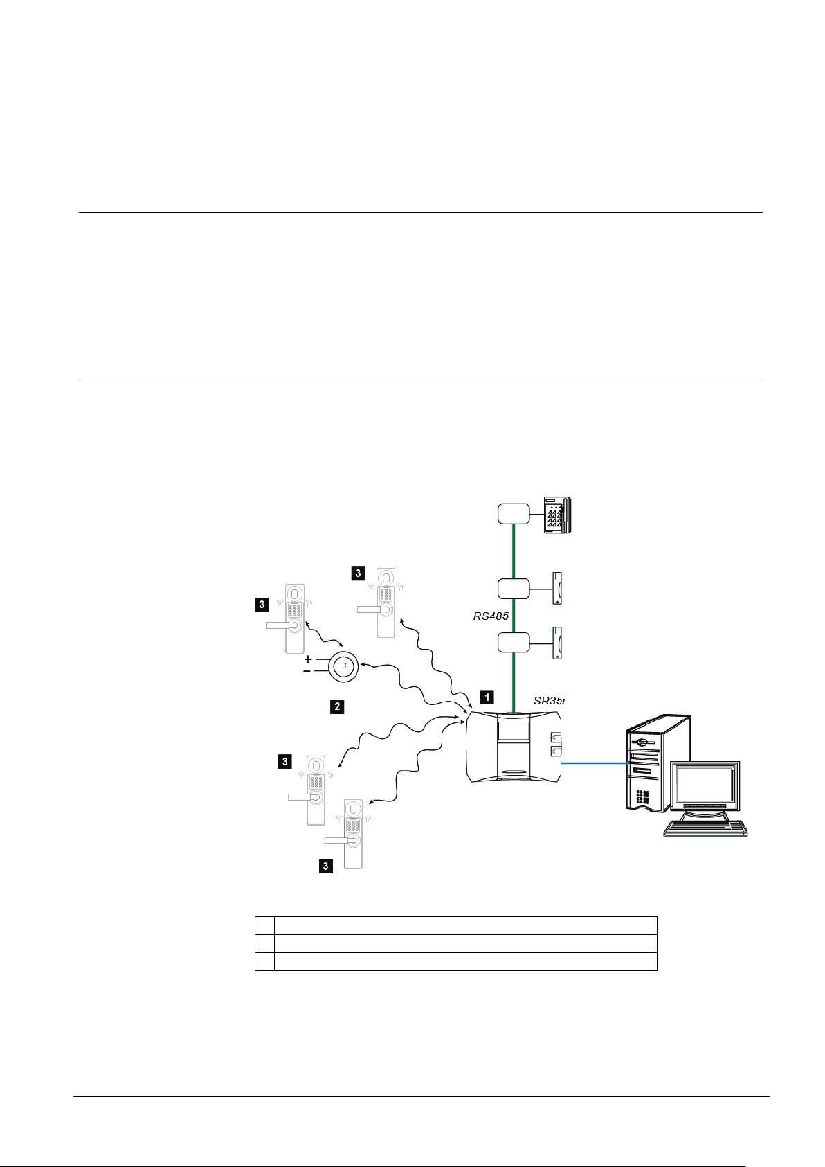
3 System description
1.
Integrated aerial in SR35i for wireless communication.
2.
RF9 Wireless router. Needs external Power supply.
3.
RF30-EM Radio Codoor.
3.1 General
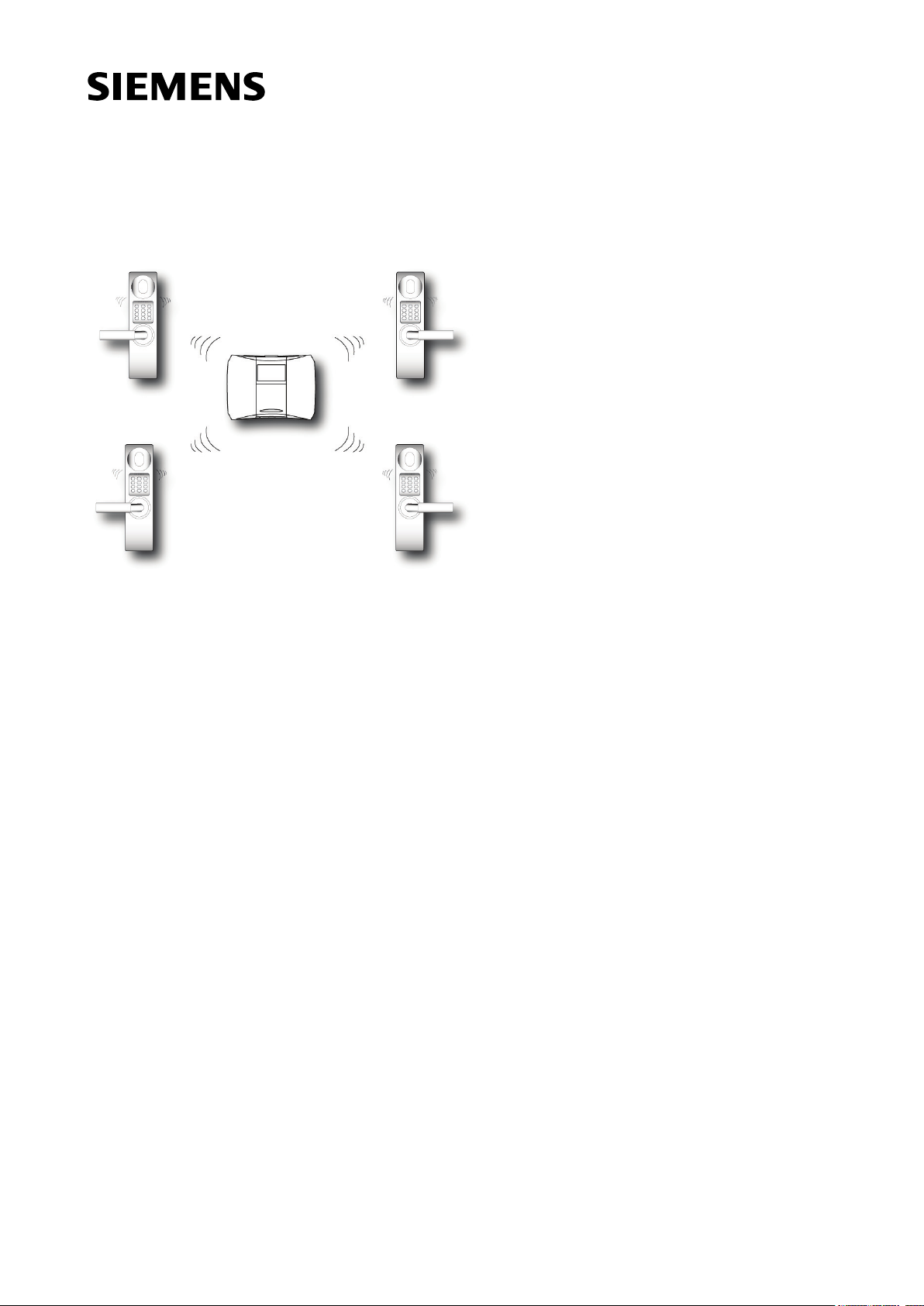
The wireless concept is designed to minimize the installation efforts when applying security products to internal doors located in offices, schools etc.
By using electro-mechanical locking devices (RF30-EM) in the door environment,
the wireless concept eliminates the need for cables from the host system to the
door.
3.2 System Components
In a wireless application we currently use mainly three components:
– SR35i, the Bewator Entro Access Control Segment controller.
System description
– RF30-EM, the door locking device.
– RF9, the optional router.
Fig. 1 Wireless system
9

System description
Siemens AB
Security Products
03.2014
3.2.1 SR35i Segment Controller
A working copy of the access control database is stored in the SR35i Segment
Controller, complete with all cardholders and their access rights. This unit is thus
able to enable or disable any access attempt at any door that it is connected to.
The SR35i can manage both wired doors (via RS485) and wireless doors (via radio).
Each Bewator Entro system can contain up to sixteen SR35i controllers.
3.2.2 RF9 Wireless router
The RF9 router is used to route and amplify the radio signal. This makes it possible
to increase the wireless connection distances. Note that the RF9 needs an exter-
nal power supply.
The RF9 also buffers messages and thus increases system performance.
3.2.3 RF30-EM Codoor
The RF30-EM is based on the well accepted Codoor unit which is mounted directly
on an existing mechanical door lock. It provides a card reader, key pad and lock
control. The unit is powered by two 9V lithium batteries. For a safe function we
strongly recommend the use of our Lithium batteries with 9V, 1200 mAh and sustaining minimum 400 mA peak current.
The unit provides not only wireless connection to an Entro system but also standalone functionality.
It also includes a PIR sensor which senses a person approaching the door. Until
the sensor is triggered, the RF30-EM saves battery life by switching off its other
features. The direction of the sensor may be adjusted to suit special cases.
By default RF30-EM is configured for stand-alone use but can very easily be reconfigured for system use.
Note: Do not mount two RF30-EM units back to back on one door. They cannot
both control the lock.
3.2.4 Bewator Entro software
Software installed in the PC is used for configuring both the database in the SR35i
and the wireless network.
Note that the access control system operates independently while the PC is shut
down.
10

Siemens AB
Security Products
03.2014
3.3 System limits
The wireless system is based on the popular Bewator Entro system.
Bewator Entro
The following limits apply to any one system:
Up to 512 wired doors (via RS485 bus)
Up to 512 wireless doors
Up to sixteen SR35i units (for 32 hard-wired + 32 wireless doors)
Wireless
The following limits apply to any one SR35i segment:
Up to nine RF9 routers may be addressed on each SR35i segment
Up to 32 door units may be addressed on each SR35i segment (requires at least
Up to 14 door units can communicate directly with each SR35i segment (without
Up to six routers can communicate directly with each SR35i
Every RF9 router can communicate with up to six more routers and with up to
Up to four RF9 routers may form a chain between SR35i and RF30-EM
System description
two RF9)
a router)
14 door units.
11

System description
Siemens AB
Security Products
03.2014
3.4 Wireless network – important concept
3.4.1 Segment ID
The Segment ID consists of four digits.
Every SR35i is identified by a unique four-digit number known as the Segment ID.
All wireless units related to this particular controller are configured with its Segment
ID.
As soon as an RF9 or RF30-EM is configured with the same Segment ID as the
SR35i it strives to communicate with that unit.
Note that in some proprietary systems using Zigbee wireless technology the expression PAN-ID (Private Area Network Identifier) is used for Segment ID. This
wireless technology is known as Zigbee (IEEE 802.15.4).
The Segment ID must not be the same as a PAN ID in another Zigbee system
nearby.
3.4.2 Address
Every unit in a Bewator Entro network must be identified by a unit address. Each
unit address is visible in the Bewator Entro software.
Each SR35i segment controller is shown as Cxx, where xx is its address. Each
RF9 or RF30-EM is shown as Cxx:Wyy (or Cxx:Ry) where xx is the address of its
SR35i and yy is the address of the wireless unit.
3.4.3 Encryption and replay protection
The Installation key, which is found in the SR35i, is the base for encrypting the
wireless communication.
There is also an integrated replay protection that eliminates any attempt to manipulate the doors.
3.4.4 Routing
All units connected to a wireless segment always “strive” to reach the highest level
– that is the SR35i. If this fails a RF9 will be used for forwarding the information (to
SR35i).
Up to four RF9 routers can form a communication chain between a SR35i and an
RF30-EM. Thus a message from the segment controller is allowed to “jump” a
maximum of five times before reaching a door unit.
12
Siemens AB
Security Products
03.2014
3.4.5 Signal strength
Service Mode
mode
25 m (free air)
Service Mode
25 m (free air)
Radio waves from any source spread out and thus become weaker with distance
from the source. Each Bewator Entro RF unit displays the strength or weakness of
the received wireless signals.
The RF30-EM shows the signal strength with the help of LEDs. The RF9 shows the
strength of the signal from the controller or intervening router with the help of
LEDs. The SR35i can display the received signal strength. The Entro software can
display the signal strength at SR35i controllers and at RF9 routers.
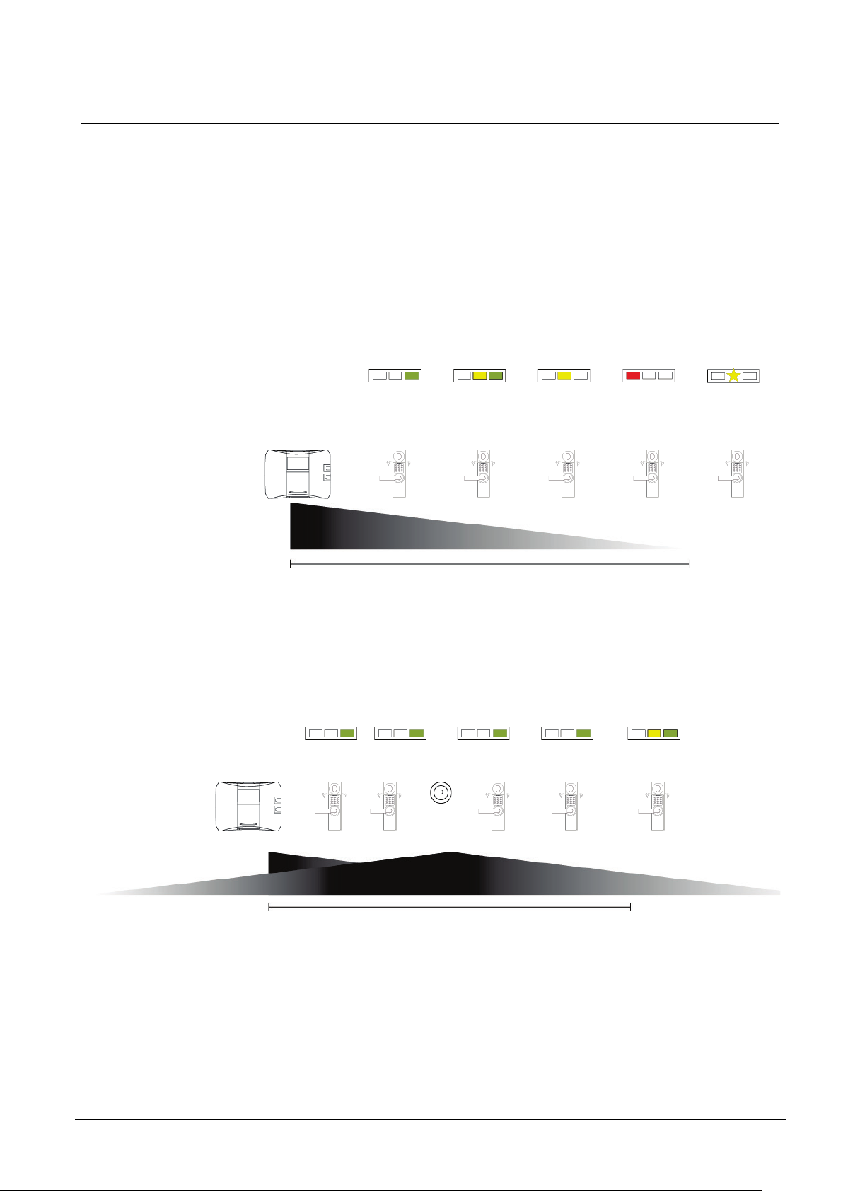
SR35i and RF30-EM
Below picture shows how mounting of the RF30-EM can be influenced by distance.
System description
Signal strength Excellent Sufficient Marginal
Improvement
recommended
Bad
Improvement
needed
Fig. 2 Example of how the signal becomes weaker with increasing distance
from SR35i.
SR35i and RF30-EM via a RF9 router
If a RF9 router is added the signal is significantly improved.
Signal strength Excellent Excellent Excellent Excellent Sufficient
No connection
RF30-EM in
autonomous
Fig. 3 Example of a SR35i with a RF9 router.
13

System description
Siemens AB
Security Products
03.2014
3.4.6 Quality of communication
Electromagnetic interference can degrade signal quality so that messages have to
be repeated.
3.4.7 Attenuation, absorption and reflection
All radio based systems are influenced by attenuation and absorption as well as reflection of the radio signal. More information is provided in Appendix A.
3.4.8 RF30-EM Service Mode
RF30-EM has an integrated Service Mode that makes the installation easier. LEDs
indicate the signal strength and quality. Most problems can be solved by adding
RF9 routers to the system as described in the RF9 configuration manual.
14

Siemens AB
Security Products
03.2014
4 Planning a wireless application
Good planning is particularly necessary for a successful wireless installation. This
section describes what to consider before the installation is started.
Read Appendix A regarding considerations for RF communication.
If hard-wired door equipment is included in the site this should be installed and
tested first. You will then have a PC available with software for checking wireless
units.
Then follow section 8 Installation to see how the practical configuration is performed.
4.1 Noise
It is advisable to try to identify in advance any noise sources that will degrade the
radio signal. Bewator Entro wireless networks use the ZigBee radio technology so
take care if other ZigBee services are installed nearby. Other sources of interference include:
Wireless computer networks (WLAN) may interfere and the frequencies for this
and the SR35i must be investigated and adjusted.
Motors, high voltage equipment or microwave equipment may interfere. Do not
mount any wireless units near these.
Avoid mounting routers in kitchens or similar because microwave ovens will in-
terfere.
Metal will attenuate but also reflect the signal.
Thick concrete structures usually include steel reinforcement bars which absorb
and scatter the signal.
Human beings also absorb and reflect the radio signal. If you hold a unit its sig-
nal will change.
Planning a wireless application
4.2 Networking guidelines
4.2.1 Frequency analyzers (sniffers)
Wireless units operate in up to 15 frequency channels (11-26) in the frequency
band 2.405 to 2.480 GHz. The SR35i may be set to avoid channels used for other
services. The most likely sources of interference in the 2.4 GHz band are wireless
Ethernet networks (Wi-Fi/802.11), Bluetooth or other systems based on ZigBee.
Take advice on channel selection from your IT manager.
A wireless unit should not be installed less than one metre from a WLAN access
point using the same frequency channel or less than 10 metre from a 3G/UTMS
base station (e g in a shopping centre or similar).
Third party products are available i e frequency analyzers, sniffers, enabling a PC
to be used as a simple tool to scan for activity on the same or adjacent actual network frequency band(s).
15
 Loading...