

Page 1

9200 Power Supply
This document discusses the installation and specifications for the following
9200 meter power supply options:
! Standard AC/DC power supply
! Low voltage DC power supply
! 480V power supply
In This Document
! Installing the Power Supply . . . . . . . . . . . . . . . . . . . . . . . . . . . . . . . . . . . . 2
! Wiring the Power Supply . . . . . . . . . . . . . . . . . . . . . . . . . . . . . . . . . . . . . . 3
Wiring the Standard AC/DC or Low Voltage DC Power Supply . . . . . . . . . . . . . . 3
Wiring the 480V Power Supply . . . . . . . . . . . . . . . . . . . . . . . . . . . . . . . . . . . . . . . . . . 4
Powering Up the Meter . . . . . . . . . . . . . . . . . . . . . . . . . . . . . . . . . . . . . . . . . . . . . . . . . 4
! Specifications . . . . . . . . . . . . . . . . . . . . . . . . . . . . . . . . . . . . . . . . . . . . . . . 5
Additional Information
! 9200 Installation and Operation Guide
© 2003 Siemens Energy & Automation. All rights reserved. The information in this document is believed to be accurate at the time of publication, however, Siemens Energy & Automation assumes no responsibility for errors which may
appear here and reserves the right to make changes without notice. ION is a registered trademark of Power Measurement Ltd. All other trademarks are property of their respective owners. Revision Date: June 3, 2003
Page 2
Replacing the Power Supply 9200 Power Supply Retrofit Ins tructions
Replacing the Power Supply
DANGER
Installation and maintenance of ACCESS meters and meter options should only be perf ormed by qualified
personnel that have appropriate training and experience with high voltage/current devices. Refer to
Installation Considerations, and the Danger, Warning, and Limitation of Liability notices in the
Installation and Operation Guide
.
1. Turn off all power to the meter.
2. Ensure that all cables still connected to the meter are not live.
3. Ensure that the Line and Neutral (or DC power) wires to the power supply
inputs of the meter are not live (if you are replacing an existing power supply).
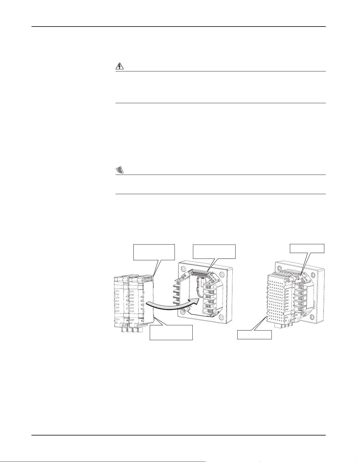
4. Fit the power supply plug-in connector to the meter plug-in port.
NOTE
All 9200 power supply models are installed the same way; the diagram for the 480V power supply is
included to show the greater depth dimension of that model.
9200
5. Tighten the two (captive) screws until the power supply fits snugly against the
meter. Do not overtighten the screws.
Plugging in the Power Supply
Power supply
plug-in connector
Front of the power
supply
9200 meter plugin port
Captive screw
Captive screw
Page 2
Page 3

9200 Power Supply Retrofit Instructions Wiring the Power Supply
Wiring the Power Supply
The meter requires a constant power supply to maintain monitoring, analysis,
control, and communications operations. Powering the device from the voltage
source it is monitoring is not suitable for applications where these operations must
be maintained in the event of a power outage.
Wiring the Standard AC/DC or Low Voltage DC Power Supply
Use 18 to 14 AWG
2
(0.8mm
to 2.1mm2) wire
+
L
G
2A fuse on L+ and N-.
DO NOT install the Nfuse in a grounded
neutral power system
-
N
Standard AC/DC Power Supply
Connect the line supply wire to the L+ terminal and the neutral supply wire to the
N- terminal.
Low Voltage DC Power Supply
Connect the positive supply wire to the L+ terminal and the negative supply wire
to the N- terminal.
The power supply G (ground) terminal must be connected to the same point as the
meter terminal.
Protective Fuses
If a Standard AC/DC or a Low Voltage DC power supply is being used, install a
Type T (slow blow) 2A fuse on the L+ conductor. If the meter is powered by a
grounded neutral power system, a fuse must NOT be installed on the neutral wire.
If the line connected to the N/- terminal is not grounded in the breaker panel, then
install a Type T (slow blow) 2A fuse on the N- terminal.
Page 3
Page 4

Wiring the 480V Power Supply 9200 Power Supply Retrofit Ins tructions
Wiring the 480V Power Supply
Use18 to 14 AWG
2
Use18 to 14 AWG
2
(0.8mm
to 2.1mm2) wire
(0.8mm
to 2.1mm2) wires
Connections to the
L1 and L2 terminals
can come from V1
and V2
100 mA fuses
on L1 and L2
480V Power Supply
Connect one phase to the L1 terminal and the other phase to the L2 terminal. You
can use the same wires from the grid that the voltage inputs use (see diagram
above).
The power supply G (ground) terminal must be connected to the same point as the
meter terminal.
Protective Fuses
The 480V power supply requires 100 mA fuses on the L1 and L2 terminals. These
should be IEC type T slow blow fuses.
NOTE
100 mA fuses can be shared with the voltage inputs.
Powering Up the Meter
After the power supply is attached to the meter, and its wiring is connected:
1. Reconnect and energize all wiring that was disconnected when the meter was
prepared for power supply installation.
Page 4
2. Power up the meter and verify correct operation.
Page 5

9200 Power Supply Retrofit Instructions Specifications
Specifications
Power Supply Rated Inputs Meter
Integrated 13 8 8 5
TRAN / RMD13895
TRAN 5353
Integrated 6 4
TRAN / RMD 7 5
TRAN 3 3
Integrated 15 12 12 10
TRAN / RMD 15121310
TRAN 11 9 11 9
Standard AC / DC
Power Supply
Low Voltage DC
Power Supply
480V Power Supply
AC: 100 – 240 VAC, 50 – 60 Hz
DC: 110 – 300 VDC
Installation category II (Local).
Pollution degree 2.
20 – 60 VDC
480 VAC, 60 Hz
Installation category III
(Distribution). Pollution degree 2.
Maximum Steady State
VA W VA W
Dielectric
Withstand
2000 VAC RMS,
60 Hz for 1 minute
3250 VAC RMS,
60 Hz for 1 minute
Page 5
 Loading...