

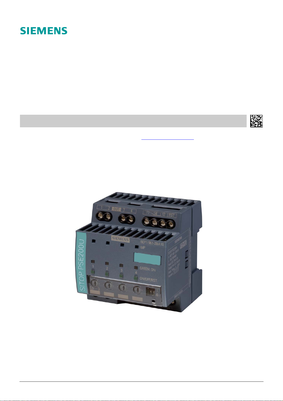
SITOP PSE200U 3 A 6EP1 961-2BA11
Selektivitätsmodul
Selectivity module
Betriebsanleitung Best.-Nr. C98130-A7579-A100-1-7419
Operating instructions
Instructions de service voir Internet
Istruzione per l'uso vedi Internet www.siemens.de/sitop
Instrucción de servicio véase Internet
SITOP PSE200U 3 A 1 / 6 C98130-A7579-A100-1-7419
Deutsch
WARNUNG / Gefahr durch elektrischen Schlag
Der Betrieb des Gerätes ist nur für den Betrieb an 24 V-Gleichspannung (Schutzkleinspannung) geeignet. Direkter Anschluss dieser Geräte an das 110 V,
230 V oder 400 V Netz, sowie Netze höherer Spannung kann deshalb zu Tod oder schweren Körperverletzungen sowie zu erheblichen Sachschäden führen.
Nur entsprechend qualifiziertes Fachpersonal darf an diesem Gerät oder in dessen Nähe arbeiten. Der einwandfreie und sichere Betrieb dieses Gerätes setzt
sachgemäßen Transport, fachgerechte Lagerung, Aufstellung und Montage voraus.
ACHTUNG
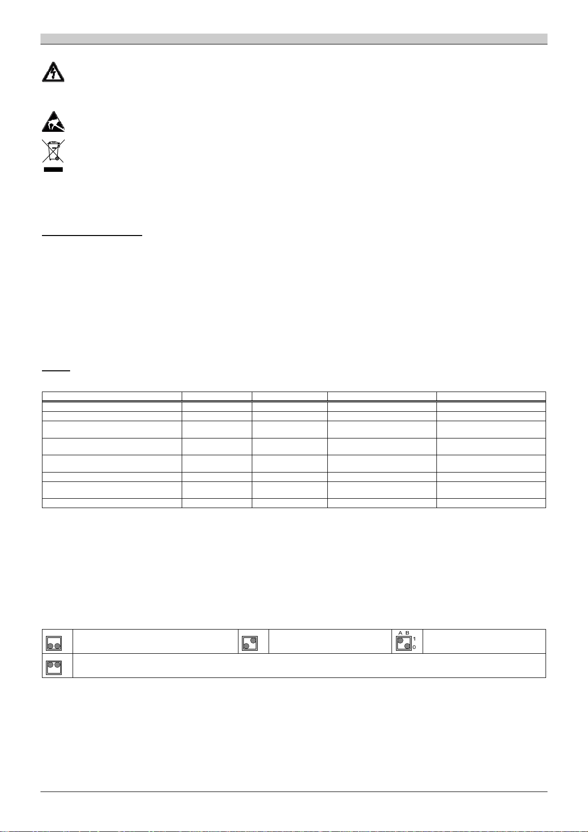
Nur geschultes Personal darf das Gerät öffnen. Elektrostatisch gefährdete Bauelemente (EGB)
Entsorgungsrichtlinien
Verpackung und Packhilfsmittel sind recyclingfähig und sollten grundsätzlich der Wiederverwertung zugeführt werden.
Das Produkt selbst darf nicht über den Hausmüll entsorgt werden.
Hinweis
Diese Betriebsanleitung enthält aus Gründen der Übersichtlichkeit nicht sämtliche Detailinformationen und kann auch nicht jeden denkbaren Fall der Aufstellung, des Betriebes oder der Instandhaltung berücksichtigen. Weiterführende Hinweise erhalten Sie über die örtliche Siemens-Niederlassung bzw. über
die Homepage http://www.siemens.de/sitop. Technische Änderungen jederzeit vorbehalten. In Zweifelsfällen gilt der deutsche Text.
Beschreibung und Aufbau
Das elektronische Selektivitätsmodul SITOP PSE200U ist ein Einbaugerät zur Montage auf Normprofilschiene DIN EN 60715-35×7,5/15 (siehe Abbildung 1). Für die
Installation des Gerätes sind die einschlägigen DIN/VDE-Bestimmungen oder länderspezifischen Vorschriften zu beachten.
SITOP PSE200U ist ausgelegt zum Anschluss an geregelte 24 V DC-Stromversorgungen mit einem Ausgangsstrom von bis zu 40 A.
Mit SITOP PSE200U kann die von einer geregelten Stromversorgung erzeugte DC 24 V Ausgangsspannung auf vier Verbraucherkreise aufgeteilt werden (siehe Abbil-
dung 2). Für jeden Ausgang (1) kann der Nennstrom mit einem Potentiometer (5) individuell im Bereich von 0,5…3 A eingestellt werden. Bei Überschreitung des
Nennstroms wird der Ausgang nach einer gewissen Zeit automatisch abgeschaltet und kann nach einer Wartezeit mittels Taster (4) oder Fern-Reset (7) wieder eingeschaltet werden. Der Taster (4) dient auch zum manuellen Schalten eines Ausgangs. Über eine LED (3) wird der Status des Ausgangs angezeigt.
Der aktuelle Ausgangsstrom eines Verteilerkreises kann durch Messen der Spannung an MP (2) gegen 0V (11) ermittelt werden. 1 V entspricht dabei 1 A.
Die Potentiometer (5) sind vorsichtig zu betätigen (max. Drehmoment ist 0,04 Nm).
Bei Anwendung unter Ex-Schutz-Bedingungen dürfen die Taster und Potentiometer nur bedient werden, wenn die direkte Umgebung des Gerätes nachweislich
zonenfrei ist.
Betrieb
Betriebszustände, Signalisierung, Reaktionen
Zustand LED Summensignal Taster wird gedrückt Fern-Reset aktiv
Gerätehochlauf 1) aus inaktiv — —
Ausgang eingeschaltet Grün aktiv
Ausgangsstrom > Nennstrom
(100 %)
Ausgang wurde automatisch
abgeschaltet
automatische Abschaltung kann
zurückgesetzt werden
Ausgang manuell ausgeschaltet 4) Orange blinkend aktiv
Ausgang defekt (interne Sicherung
hat ausgelöst)
Geräteübertemperatur 5) rotes Lauflicht inaktiv — —
1) Nach Abschluss des Gerätehochlaufs werden die Ausgänge unter Beachtung der eingestellten Zuschaltverzögerung eingeschaltet. ⇒
2) Der Ausgang wird gemäß Abschaltcharakteristik automatisch abgeschaltet. ⇒
3) Nach einer Wartezeit von typ. 20 Sekunden kann der Ausgang wieder eingeschaltet werden. ⇒
Die noch offene Wartezeit wird beim Ausschalten des Geräts gespeichert und beim Wiedereinschalten abgewartet.
4) Der Zustand wird beim Ausschalten des Geräts gespeichert.
5) Nach dem Abklingen der Übertemperatur kann der Ausgang wieder eingeschaltet werden. ⇒
Einstellung der Zuschaltverzögerung
Die Zuschaltung der Ausgänge erfolgt nach dem Erreichen einer Mindesteingangsspannung (Zuschaltschwelle) automatisch.
Bei bestimmten Lasten kann ein sequentielles Zuschalten erforderlich sein, um Einschaltspitzenströme zu reduzieren. Zu diesem Zweck kann über einen 2-poligen
Schalter (9) eine von vier möglichen Varianten ausgewählt werden. Dabei werden die Ausgänge zeitverzögert zueinander in fester Reihenfolge (Ausgang 1 » 2 » 3 »4)
zugeschaltet.
AB
keine Verzögerung, alle vier Ausgänge werden
1
gleichzeitig zugeschaltet (Auslieferungszustand)
0
AB
lastabhängiges Zuschalten:
1
der nächste Ausgang wird zugeschaltet, sobald beim vorherigen Ausgang der Strom unter dem eingestellten Nennwert liegt
0
2) Grün blinkend aktiv
3) Rot inaktiv — —
Rot blinkend inaktiv
aus inaktiv — —
AB
25 ms Verzögerung zwischen dem
1
Zuschalten der Ausgänge
0
Ausgang abschalten, ⇒
Ausgang abschalten, ⇒
Ausgang einschalten, ⇒
Ausgang einschalten, ⇒
Ausgang einschalten, ⇒
—
—
—
100 ms Verzögerung zwischen dem
Zuschalten der Ausgänge
SITOP PSE200U 3 A 2 / 6 C98130-A7579-A100-1-7419

Deutsch
Abschaltcharakteristik
Für die automatische Abschaltung eines Ausgangs können drei Bereiche unterschieden werden (typische Werte; siehe auch Abbildung 3):
Ausgangsstrom zu Nennstrom 0 … 100 % 101 … 130 % > 130 %
Bereich Normal Überstrom Strombegrenzung
Eingangsspannung > 20 V keine Abschaltung Abschaltung nach ca. 5 s Strombegrenzung auf ca. 130 %;
Eingangsspannung < 20 V Abschaltung nach ca. 5 s Sofortabschaltung
Eingangsspannung > 30 V Sofortabschaltung
Abschaltung in Abhängigkeit von Nennstrom und
Eingangsspannung frühestens nach typ. 100 ms
Technische Daten
Eingangsgrößen
Eingangsnennspannung:
DC 24 V
Arbeitsspannungsbereich:
DC 20,4…30 V
Zuschaltschwelle:
ca. 20 V
Eingangsdauerstrom:
typ. 12 A / max. 15 A
Ausgangsgrößen
Ausgangsnennspannung:
DC 24 V, entsprechend der Eingangsspannung
Spannungsabfall bei 3 A pro Ausgang:
typ. 150 mV
Einstellbereich des Ausgangsstromes:
0,5…3 A, Einstellung mittels Potentiometer
Zuschaltverzögerung:
identisch zwischen den Ausgängen (Einstellwerte
0 ms, 25 ms, 100 ms) oder lastabhängig
Umgebung
Temperatur
Lagerung und Transport: –25 … +85 °C
Betrieb: 0 … +60 °C
Feuchteklasse:
entsprechend Klimaklasse 3K3 nach EN 60721-3,
keine Betauung
Luftselbstkühlung
Signalisierung
Eine LED (3) zur Anzeige des Status je Ausgang.
Summenmeldekontakt (7):
potenzialfreier Relaiskontakt (Wechsler),
im Zustand „inaktiv“ sind 11 und 12 verbunden
sowie 11 und 14 geöffnet
Kontaktbelastbarkeit: 24 V / 0,1 A
Fern-Reset (7):
nicht potentialgetrennter 24 V Eingang (bezogen
auf den 0V Eingang (11) des Geräts);
bei einer Spannung > 15 V wird der Eingang als aktiv
betrachtet
Sicherheit
Das Gerät ist gegen Verpolung der Eingangsspannung geschützt.
Jeder Ausgang ist mit einer internen, nicht auswechselbaren 5 A Sicherung geschützt.
Vorschriften
Schutzart: IP20 nach EN 60529
Schutzklasse: III nach EN 61140
Sicherheit nach EN 50178 und EN 60950: SELV
Störaussendung: nach EN 61000-6-3
Störfestigkeit: nach EN 61000-6-2
CE-Konformität gemäß 2004/108/EG und 94/9/EG
UL 2367, File E328600
cURus (UL 60950, CSA C22.2 No. 60950) in
Vorbereitung
ATEX nach IEC/EN 60079-15:
EPS 09 ATEX 1 169 X
II 3G Ex nAC II T4
Gewicht
170 g
Montagehinweise
Montage auf Normprofilschiene DIN EN 60715-35×7,5/15. Das Gerät ist zwecks ordnungsgemäßer Entwärmung vertikal so zu montieren, dass die Eingangsklemmen
(6, 11) unten und die Ausgangsklemmen (1, 7) oben sind. Oberhalb und unterhalb des Gerätes soll mindestens ein Freiraum von je 50 mm eingehalten werden.
Zum Aufschnappen das Gerät mit der Nase (A) in die Hutschiene (C) einhängen und andrücken bis die Feder (B) einrastet. Zur Demontage von der Hutschiene mit
Schraubendreher die Feder (B) in Pfeilrichtung lösen und Gerät abnehmen (siehe Abbildung 1).
Bei Ex-Anwendungen muss sichergestellt werden, dass nach Installation die Schutzart IP 54 erreicht wird.
Nach der Einstellung des Geräts kann die Abdeckung der Potentiometer (5) und des Schalter (9) plombiert werden (10).
Zur Gerätekennzeichnung kann ein Schild SKS/PC 20x7 eingelegt werden (8).
Anschluss und Klemmenbelegung
Klemmen Funktion Klemmbereich Bemerkungen
IN +24V (6) Anschluss Eingangsspannung DC +24 V
0V (11) Anschluss DC 0 V zur Versorgung der internen Elektronik
OUT 1, 2, 3, 4 (1) Ausgänge zum Anschluss der Verbraucherkreise
11, 12, 14 (7) potentialfreier Summenmeldekontakt (Wechsler)
RST (7) Fern-Reset
Der 0 V-Anschluss (11) des Gerätes dient lediglich der Versorgung der internen Elektronik.
Die 0 V der Verbraucher sind über getrennte Leitungen direkt zur Stromversorgung zu führen.
Die externe Beschaltung aller Klemmen (auch Signal- und Meldekontakte) muss den Anforderungen an SELV-Kreise nach VDE 0805 / EN 60950 genügen.
(vom “+“ -Ausgang der Stromversorgung)
(vom “–“ -Ausgang der Stromversorgung )
0,5…10 mm
20…7 AWG
0,5…4 mm
20…10 AWG
2
2
Schraubklemmen;
verwenden Sie einen 1,0×5,5 mm oder PZ 2
Schraubendreher;
empfohlenes Anzugsmoment ist 1,2 Nm
Schraubklemmen;
verwenden Sie einen 0,6×3,5 mm oder PZ 1
Schraubendreher;
empfohlenes Anzugsmoment ist 0,6 Nm
SITOP PSE200U 3 A 3 / 6 C98130-A7579-A100-1-7419

English
WARNING / Danger of electric shock
This device is only suitable for operation with 24 V DC voltage (safety extra-low voltage). Direct connection of these devices to the 110 V, 230 V or 400 V
power system, or to power systems with a higher voltage, may consequently result in death, severe personal injury or substantial property damage. Only
qualified personnel should work on or around this equipment. The product will function correctly and safely only if it is transported, stored, set up and
installed as intended.
CAUTION
The device may only be opened by qualified personnel. Electrostatic sensitive devices (ESD)
Disposal guideline
Packaging and packing aids can be recycled and should always be disposed of for reuse.
The product itself shall not be disposed of as normal domestic waste.
Note
These operating instructions cannot claim to cover all details of the product, nor to provide for every possible contingency to be met in connection with
installation, operation or maintenance. For more information, please contact your local Siemens office or consult our Web site http://www.siemens.de/sitop.
Subject to change without prior notice. The German text applies if any doubt exists.
Description and design
The SITOP PSE200U electronic selectivity module is a built-in unit for mounting on standard rail DIN EN 60715-35x7.5/15 (see figure 1). It must be installed taking into
account all relevant DIN/VDE specifications and other national standards.
SITOP PSE200U is designed to be connected to stabilized 24 V DC power supplies with an output current up to 40 A.
SITOP PSE200U allows the 24 V DC output voltage generated by a stabilized power supply to be split between four load circuits (see figure 2). The rated current for
each output (1) can be set individually with a potentiometer (5) in the range of 0.5…3 A. If the rated current is exceeded for a certain time, the output will be
switched off automatically and can be switched on after a waiting time using the pushbutton (4) or the remote reset (7). The pushbutton (4) can also be used to
switch the output manually. The state of an output is indicated with a LED (3).
The actual output current of a load circuit can be determined by measuring the voltage at MP (2) against 0V (11). 1 V corresponds to 1 A.
The potentiometers (5) shall be actuated with care (max. torque is 0.04 Nm).
If used under hazardous conditions, the pushbuttons and potentiometers may only be actuated if the immediate environment of the device is provenly not
classified as a hazardous area.
Operation
Operating states, Signaling, Reactions
State LED Common signal Pushbutton pressed Remote reset active
run-up of device 1) off inactive — —
output switched on green active
output current > rated current 2) green flashing active
output was switched off auto-
matically
reset of automatic switch-off
possible
output switched off manually 4) orange flashing active
output malfunction (internal fuse
blown)
excess temperature of device 5) red running light inactive — —
1) After the run-up of the device the outputs are switched on considering the programmed switch-on delay. ⇒
2) The output is automatically deactivated in accordance with switch-off characteristics. ⇒
3) After a waiting period of typ. 20 seconds the output can be switched on. ⇒
The unexpired waiting time is stored when the device is switched off and elapses when it is switched on again.
4) The state is saved at power-off of the device.
5) After the decay of the excess temperature the output can be switched on again. ⇒
Programming sequential switch-on delay
The outputs will be switched on automatically after reaching a minimum input voltage (connection threshold).
Sequential switch-on might be required for specific loads in order to reduce inrush surge currents. For this purpose it is possible to select one of four alternatives with
a 2-pole switch (9). The outputs are connected in a fixed order (output 1 » 2 » 3 »4).
AB
no delay, all four outputs are connected at the same
1
time (delivery state)
0
AB
load dependent connection:
1
the next output will be connected as soon as the current of the previous output is less than the rated current
0
3) red inactive — —
red flashing inactive
off inactive — —
AB
25 ms delay between the connection
1
of the outputs
0
switch off output, ⇒
switch off output, ⇒
switch on output, ⇒
switch on output, ⇒
switch on output, ⇒
—
—
—
100 ms delay between the connection
of the outputs
SITOP PSE200U 3 A 4 / 6 C98130-A7579-A100-1-7419

English
Switch-off characteristic
For the automatic switch-off of an output three ranges can be distinguished (typical values; see also figure 3):
output current to rated current 0 … 100 % 101 … 130 % > 130 %
range normal overcurrent current limiting
input voltage > 20 V no disconnection disconnection after approx. 5 s current limiting to approx. 130 %;
input voltage < 20 V disconnection after approx. 5 s immediate disconnection
input voltage > 30 V immediate disconnection
disconnection after typ. 100 ms depending on rated
output current and input voltage
Technical data
Input variables
Rated input voltage:
DC 24 V
Working voltage range:
DC 20.4…30 V
Connection threshold:
approx. 20 V
Continuous input current:
typ. 12 A / max. 15 A
Output variables
Rated output voltage:
DC 24 V, equivalent to input voltage
Voltage drop at 3 A per output:
typ. 150 mV
Output current setting range:
0.5…3 A, set with potentiometer
Switch-on delay:
for all outputs alike (setting values: 0 ms, 25 ms,
100 ms) or load dependent
Ambient
Temperature
Storage and transport: –25 … +85 °C
Operation: 0 … +60 °C
Humidity rating:
corresponds to climatic category 3K3 acc. to
EN 60721- 3, no condensation
Natural air cooling
Signaling
One LED (3) to indicate the state per output.
Common signaling contact (7):
floating relay contact (changeover contact),
11 and 12 connected when inactive, 11 and 14
are open.
contact rating: 24 V / 0.1 A
Remote reset (7):
non-isolated 24 V input (related to the 0V input
(11) of the device);
considered as active for voltages > 15 V
Safety
The device is protected against polarity reversal of
the input voltage.
Each output is protected by an internal, nonexchangeable 5 A fuse.
Specifications
Degree of protection: IP20 acc. to EN 60529
Safety class: III acc. to EN 61140
Safety acc. to EN 50178 and EN 60950: SELV
Emitted interference: acc. to EN 61000-6-3
Noise immunity: acc. to EN 61000-6-2
CE marking acc. to 2004/108/EC and 94/9/EC
UL 2367, File E328600
cURus (UL 60950, CSA C22.2 No. 60950) in
preparation
ATEX acc. to IEC/EN 60079-15:
EPS 09 ATEX 1 169 X
II 3G Ex nAC II T4
Weight
170 g [0.4 lb.]
Installation instructions
Mounting on a DIN EN 60715-35x7.5/15 standard rail. The device must be installed vertically with the input terminals (6, 11) at the bottom and the output terminals
(1, 7) at the top, in order to ensure adequate heat dissipation. A clearance of at least 50 mm must be left above and below the device.
To snap the device on to the rail, hang it with its lug (A) on the rail (C) and press until the spring (B) snaps into place. To remove it from the DIN rail, use a screwdriver
to loosen the spring (B) in the direction of the arrow and take off the device (see figure 1).
In Ex applications it must be ensured that installation is according to protection class IP 54.
After adjusting the device the cover of the potentiometer (5) and the switch (9) can be sealed (10).
To mark the device a label SKS/PC 20x7 can be inserted (8).
Connections and terminal assignment
Terminals Function Terminal area Remarks
IN +24V (6) DC +24 V input voltage connection
0V (11) DC 0 V connection for supplying the internal electronic circuits
OUT 1, 2, 3, 4 (1) outputs for connecting the load circuits
11, 12, 14 (7) floating common signaling contact (changeover contact)
RST (7) remote reset
The 0 V connection (11) of the device merely serves to supply the internal electronic circuits.
The 0 V of the loads must be supplied directly to the power supply by means of separate lines.
The external circuitry of all terminals (including signaling and status contacts) must meet the safety requirements stipulated by VDE 0805 / EN 60950: SELV.
(from "+" output of the power supply)
(from "–" output of the power supply)
0.5…4 mm
20…7 AWG
0.5…4 mm
20…10 AWG
2
2
screw-type terminals;
use a 1.0×5.5 mm or PZ 2 screwdriver;
recommended tightening torque 1.2 Nm
screw-type terminals;
use a 0.6×3.5 mm or PZ 1 screwdriver;
recommended tightening torque 0.6 Nm
SITOP PSE200U 3 A 5 / 6 C98130-A7579-A100-1-7419

Abbildungen und Tabellen / Figures and tables
80
Abbildung 1: Maßbild (mm) / Figure 1: Dimension drawing (mm)
DC
+
DC 24 V
–
RST
11
14
Steuerlogik / Control logic
AC
12
OUT 1 OUT 2 OUT 3 OUT 4
Last 1 / Load 1 Last 2 / Load 2 Last 3 / Load 3 Last 4 / Load 4
Abbildung 2: Blockschaltbild / Figure 2: Block diagram
100 s
10 s
1 s
t
0,1 s
5 s
0V IN +24V
SITOP PSE200U
0 s
I / I
n
Abbildung 3: Abschaltcharakteristik (typisch) / Figure 3: Disconnection characteristic (typical)
Herausgegeben von:
SIMEA
Bereich IA&DT
Siemensstraße 92
1210 Wien
Österreich
Published by:
SIMEA
IA&DT Group
Siemensstraße 92
1210 Vienna
Austria
160 %140 %120 %100 %80 %60 %40 %20 %0 %
© Siemens AG Österreich 12/2009. All rights reserved
Liefermöglichkeiten und technische Änderungen vorbehalten
Availability and technical specifications subject to change without prior notice
Bestellnummer / Order number C98130-A7579-A100-1-7419
SITOP PSE200U 3 A 6 / 6 C98130-A7579-A100-1-7419
 Loading...