

Page 1
SIRIUS
Sanftstarter 3RW40
Soft starter 3RW40
Démarreur progressif 3RW40
Arrancador suave 3RW40
Avviatore dolce 3RW40
Chave de partida suave 3RW40
Yumuşak yol verici 3RW40
Устройство плавного пуска 3RW40
软启动器 3RW40
3RW40 2
3RW40 3
3RW40 4
EN/IEC 60947-4-2
Sanftstarter 3RW40
DE
Sicherheits- und Inbetriebnahmehinweise für explosionsgefährdete Bereiche — Bestell-Nr.: 3ZX1012-0RW40-1CA1
EN
Safety and commissioning instructions for hazardous areas — Order No.: 3ZX1012-0RW40-1CA1
FR
Consignes de sécurité et de mise en service pour les zones explosibles — N° de référence : 3ZX1012-0RW40-1CA1
ES
Instrucciones de seguridad y puesta en servicio en entornos con peligro de explosión — Referencia: 3ZX1012-0RW40-1CA1
Indicazioni di sicurezza e per la messa in servizio in aree con pericolo d‘esplosione — N° di ordinaz.: 3ZX1012-0RW40-1CA1
PT
Indicações de segurança e de colocação em funcionamento para áreas apresentando risco de explosão —
Nº de enc.: 3ZX1012-0RW40-1CA1
TR
Patlama tehlikesi altında bulunan bölgeler için emniyet ve hizmete alma bilgileri — Sipariş no.: 3ZX1012-0RW40-1CA1
PY
Указания по технике безопасности и вводу в эксплуатацию во взрывоопасных зонах — № заказа: 3ZX1012-0RW40-1CA1
用于受爆炸威胁区域的安全及首次启动运行说明 — 订购编号 : 3ZX1012-0RW40-1CA1
Betriebsanleitung — Bestell-Nr.: 3ZX1012-0RW40-2DA1
Grafiken 29 - 32
Soft starter 3RW40
Operating instructions — Order No.: 3ZX1012-0RW40-2DA1
Graphics 29 - 32
Démarreur progressif 3RW40
Instructions de service — N° de référence : 3ZX1012-0RW40-2DA1
Graphiques 29 - 32
Arrancador suave 3RW40
Instructivo — Referencia: 3ZX1012-0RW40-2DA1
Gráficos 29 - 32
Avviatore dolce 3RW40
Istruzioni operative — N° di ordinaz.: 3ZX1012-0RW40-2DA1
IT
Grafiche 29 - 32
Chave de partida suave 3RW40
Instruções de Serviço — Nº de enc.: 3ZX1012-0RW40-2DA1
Gráficos 29 - 32
Yumuşak yol verici 3RW40
İşletme kılavuzu — Sipariş no.: 3ZX1012-0RW40-2DA1
Grafikler 29 - 32
Устройство плавного пуска 3RW40
Инструкция по эксплуатации —№ заказа: 3ZX1012-0RW40-2DA1
Графики 29 - 32
软启动器 3RW40
中
操作规程 - 订货号: 3ZX1012-0RW40-2DA1 第 26 - 28
文
图表
和 29 - 32 页
Seite
2 - 4
Page
5 - 7
Page
8 - 10
Página
11 - 13
Pagina
14 - 16
Página
17 - 19
Sayfa
20 - 22
Cтраница
23 - 25
www.siemens.com/lowvoltage/manuals
SIRIUS-Systemhandbuch / SIRIUS system manual : http://www.siemens.de/sirius-systemhandbuch
Technical Assistance: Telephone: +49 (0) 911-895-5900 (8°° - 17°° CET) Fax: +49 (0) 911-895-5907
E-mail: technical-assistance@siemens.com
Internet: www.siemens.de/lowvoltage/technical-assistance
Technical Support: Telephone: +49 (0) 180 50 50 222
GWA 4NEB 535 1993-10 DS 05 Last update: 07 February 2008
Page 2
Deutsch
!
!
1
1
3
5
2
4
6
a
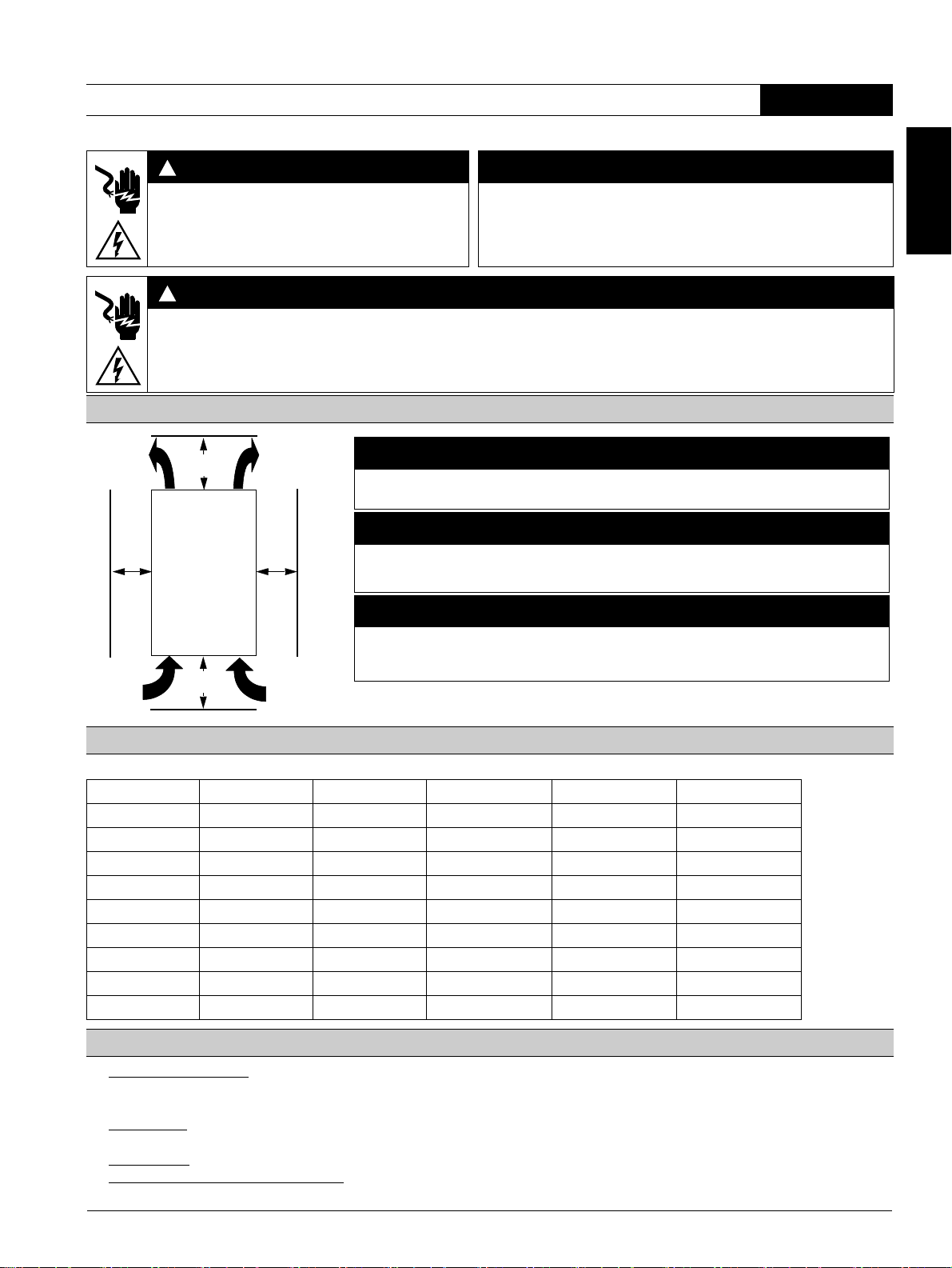
≥ 60 mm
[≥ 2.36 in]
≥ 40 mm
[≥ 1.56 in]
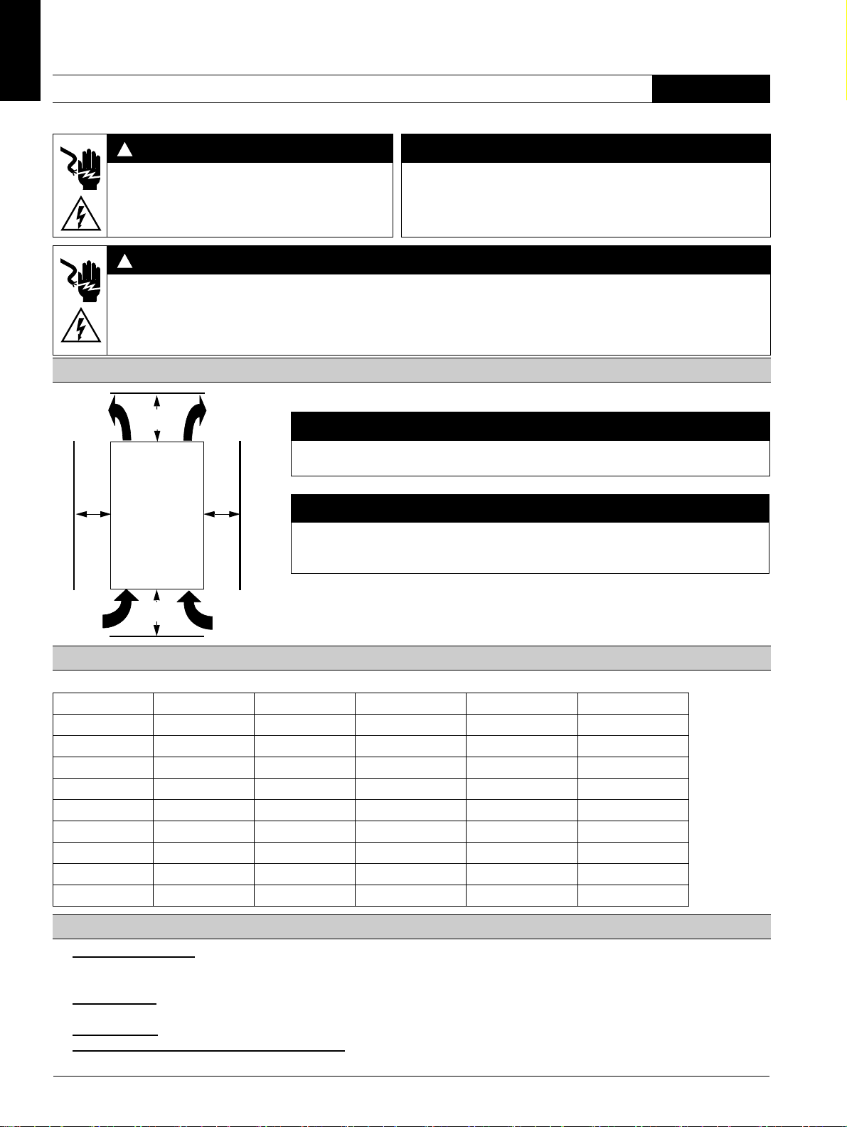
ACHTUNG
Beachten Sie beim Einbau des Geräts die angegebenen Abstände, damit genügend Luft für
Kühlung zirkulieren kann. Das Gerät wird von unten nach oben belüftet.
VORSICHT
Gefahr von Sachschäden.
Achten Sie darauf, dass keine Flüssigkeit, kein Staub oder leitender Gegenstand in den
Sanftstarter gelangt.
a
a) 3RW40 2: 15 mm [0.59 in]
3RW40 3; 3RW40 4: 30 mm [1.18 in]
Sanftstarter 3RW40 2, 3RW40 3, 3RW40 4 Deutsch
Vor der Installation, dem Betrieb oder der Wartung des Geräts muss diese Anleitung gelesen und verstanden werden.
GEFAHR
VORSICHT
Gefährliche Spannung.
Lebensgefahr oder schwere Verletzungsgefahr.
Vor Beginn der Arbeiten Anlage und Gerät
Eine sichere Gerätefunktion ist nur mit zertifizierten Komponenten
gewährleistet!
spannungsfrei schalten.
GEFAHR
Gefährliche Spannung.
Lebensgefahr oder schwere Verletzungsgefahr.
Um elektrischen Stromschlag oder Verbrennungen zu vermeiden, dürfen die Klemmen des Motorsteuergeräts nicht berührt werden,
wenn das Gerät mit Spannung versorgt wird. An den Ausgangsklemmen steht auch im AUS-Zustand des Motorsteuergeräts Spannung
an.
Einbauabstände in Einzelaufstellung (Dicht-an-dicht-Aufstellung siehe Sanftstarter-Handbuch)
Motorstromeinstellwerte
Zulässige Motorstromeinstellwerte in Abhängigkeit von der CLASS-Einstellung bei 40° C Umgebungstemperatur
Ie [A] I
3RW40 24-... 12,5 5 12,5 11 10
3RW40 26-... 25,3 10,3 25,3 23 21
3RW40 27-... 32,2 17,2 32,2 30 27
3RW40 28-... 38 23 38 34 31
3RW40 36-... 45 22,5 45 42 38
3RW40 37-... 63 25,5 63 50 46
3RW40 38-... 72 34,5 72 56 50
3RW40 46-... 80 42,5 80 70 64
3RW40 47-... 106 46 106 84 77
Programmieren des ON/RUN Ausgangs 13/14 (Werkseinstellung: ON) (Grafikteil, Bild 3)
1. Programmierung starten:
(Beim Gerät 3RW40 2 die Abdeckung wie in Bild 2 gezeigt entfernen.) Die Taste "RESET MODE" (2) länger als 2 s
drücken, bis die LED "DEVICE" (5) grün flimmert. Die Taste "RESET MODE" (2) gedrückt halten und zusätzlich die Taste "RESET/TEST" (1)
länger als 1 s drücken, bis die LED "DEVICE" (5) am Gerät rot leuchtet.
2. Modus anzeigen:
Modus.
3. Modus wechseln:
4. Programmierung beenden und Einstellungen speichern: Taste "RESET/TEST" (1) länger als 1 s drücken, bis die LED "DEVICE" (5) grün
leuchtet.
LED "STATE/BYPASSED/FAILURE" (6) blinkt grün: ON-Modus. LED "STATE/BYPASSED/FAILURE" (6) flimmert grün: RUN-
Taste "RESET MODE" (2) drücken.
[A] I
min
[A] CLASS 10 I
max
[A] CLASS 15 I
max
[A] CLASS 20
max
2 3ZX1012-0RW40-2DA1
Page 3
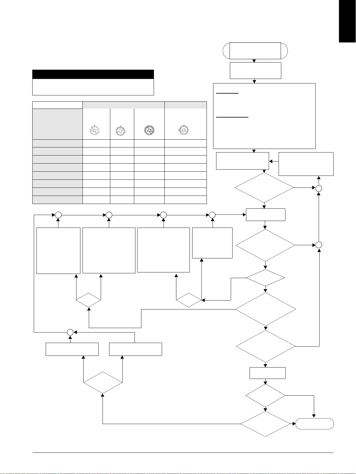
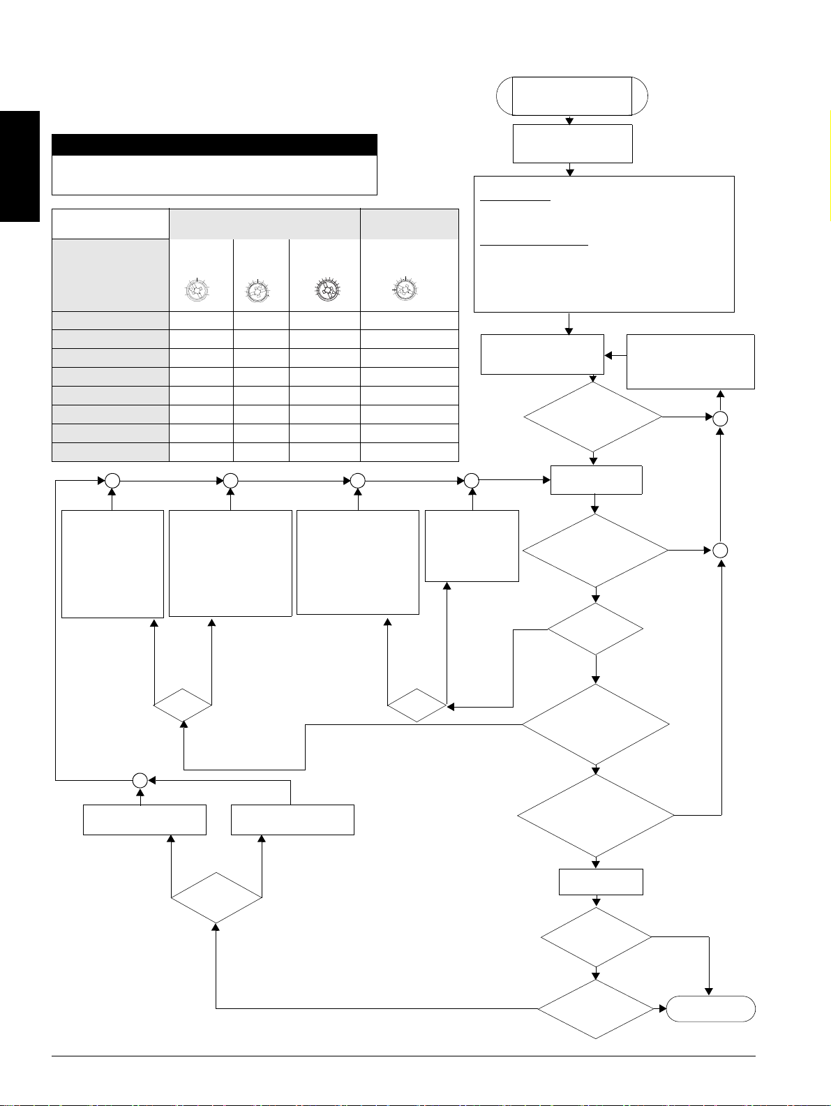
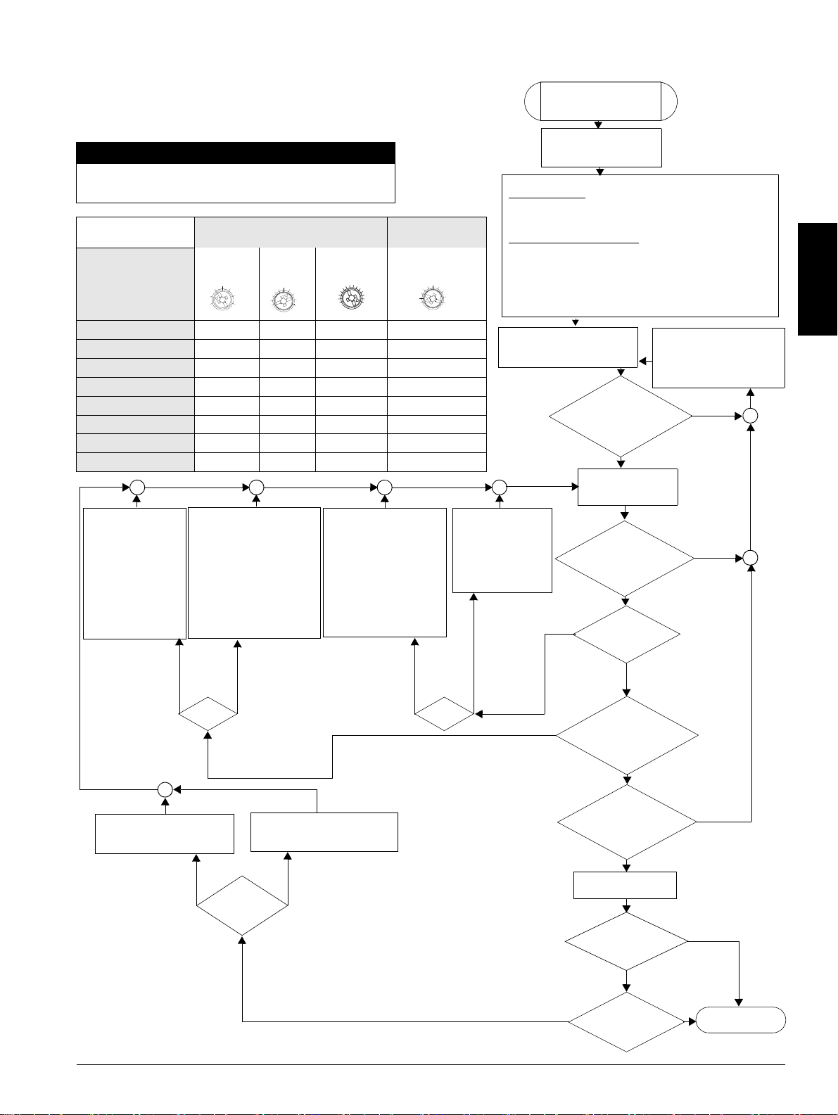
Schnellinbetriebnahmeanleitung
1. Sanftstarter ausschalten
(IN 1 -> 0).
2. Anlaufzeit reduzieren
(Poti nach links drehen)
oder
3. wenn Strombegrenzung
eingestellt ist, Begrenzungswert erhöhen (Poti
nach rechts drehen).
1. Sanftstarter ausschalten (IN 1 -> 0).
2. Anlaufzeit erhöhen
(Poti nach
rechts drehen).
3. Strombegrenzungswert reduzieren
(Poti nach
links drehen).
1. Sanftstarter ausschalten
(IN 1 -> 0).
2. Startspannung erhöhen
(Poti nach rechts drehen)
oder
3. wenn Strombegrenzung
eingestellt ist, Begrenzungswert erhöhen (Poti
nach rechts drehen).
1. Sanftstarter ausschalten (IN 1 -> 0).
2. Startspannung
reduzieren (Poti
nach links drehen).
Der Motor erreicht
seine Nenndrehzahl
- mit zu schnellem
Momentenanstieg
- schneller als
gewünscht,
mit zu hohem
Anlaufstrom
Der Motor
erreicht seine
Nenndrehzahl
- langsamer als
gewünscht
- gar nicht
(bleibt hängen)
Der Motor
läuft nicht
sofort los
und brummt
Motor:
Der Motor
läuft mit
Momentenschlag an
Auslaufzeit erhöhen
(Poti nach rechts drehen)
Auslaufzeit reduzieren
(Poti nach links drehen)
Sanftauslauf
Der Motor bleibt
abrupt, nicht sanft
stehen.
Der Motor läuft zu
lange nach.
Schnellinbetriebnahme
3RW40 SIRIUS
Sanftstarter
1. Verdrahtungskontrolle
- Steuerteil und
- Leistungsteil
2. Gerät parametrieren
Motorschutz
- am Ie-Einsteller Motorbemessungsstrom des
Antriebs einstellen
- am CLASS-Schalter erforderliche Abschaltklasse
einstellen.
Sanftstartfunktion
- Strombegrenzungswert (x Ie)
- Anlaufzeit (s)
- Startspannung (%)
- Auslaufzeit (s)
auf gewünschte Werte einstellen (siehe Tabelle
Einstellungsvorschlag).
3. Spannungen im Steuer-
und Hauptstromkreis überprüfen und zuschalten.
Über LED-Anzeige und
Zustandstabelle Fehlerursache ermitteln und beheben.
(siehe Seite 4)
LED "DEVICE"
grünes Dauerlicht,
die anderen LEDs
sind aus?
nein
4. Sanftstarter einschalten (IN 0 -> 1)
LEDs:
"DEVICE" grün Dauerlicht,
"STATE/BYPASSED"
blinkt grün?
Motor läuft
sanft an?
Motor
erreicht zügig,
innerhalb der gewünschten
Zeit seine Nenn-
drehzahl?
LEDs:
"DEVICE" grün
Dauerlicht, "STATE/
BYPASSED" grün
Dauerlicht?
Sanftstarter aus-
schalten (IN 1 -> 0)
Welche
Auslaufart ist
gewählt?
Motor
kommt wie gewünscht
zum Stillstand?
Inbetriebsetzung
beendet
Motor:
nein
nein
nein
nein
nein
Thermistoranschluss (nur 3RW40.-.TB0.)
– Anschluss Thermoclick gemäß Bild 6.3 (Drahtbrücke entfernen)
– Anschluss PTC Typ A gemäß Bild 6.4 (Drahtbrücke entfernen)
VORSICHT
Gefahr von Sachschäden.
Anschluss an nicht belegte Klemmen ist unzulässig.
Einstellungsvorschlag Anlauf Parameter Auslauf Parameter
Start-
spannung %
Anlaufzeit s
Strombegren-
zungswert
Auslaufzeit s
Applikation
Förderband
70 10
5xI
e
5
Rollenförderer
60 10
5xI
e
5
Kompressor
50 10
4xI
e
0
kleiner Ventilator
40 10
4xI
e
0
Pumpe
40 10
4xI
e
10
Hydraulikpumpe
40 10
4xI
e
0
Rührwerk
40 20
4xI
e
0
Fräsmaschine
40 20
4xI
e
0
40
100%
0
5
10
20s
e
xI
5
1.3
5
10
0
20s
Sanftauslauf
ja
ja
ja
ja
ja
ja
ja
ja
Freier Auslauf
Deutsch
3ZX1012-0RW40-2DA1 3
Page 4
Deutsch
gngngn
gn
gn
gngngn
gn
gn
ylw
rd
gn
rd
gn
gn
ylw
rd
gnrdrdrdgn
rd
ylw
gn
!
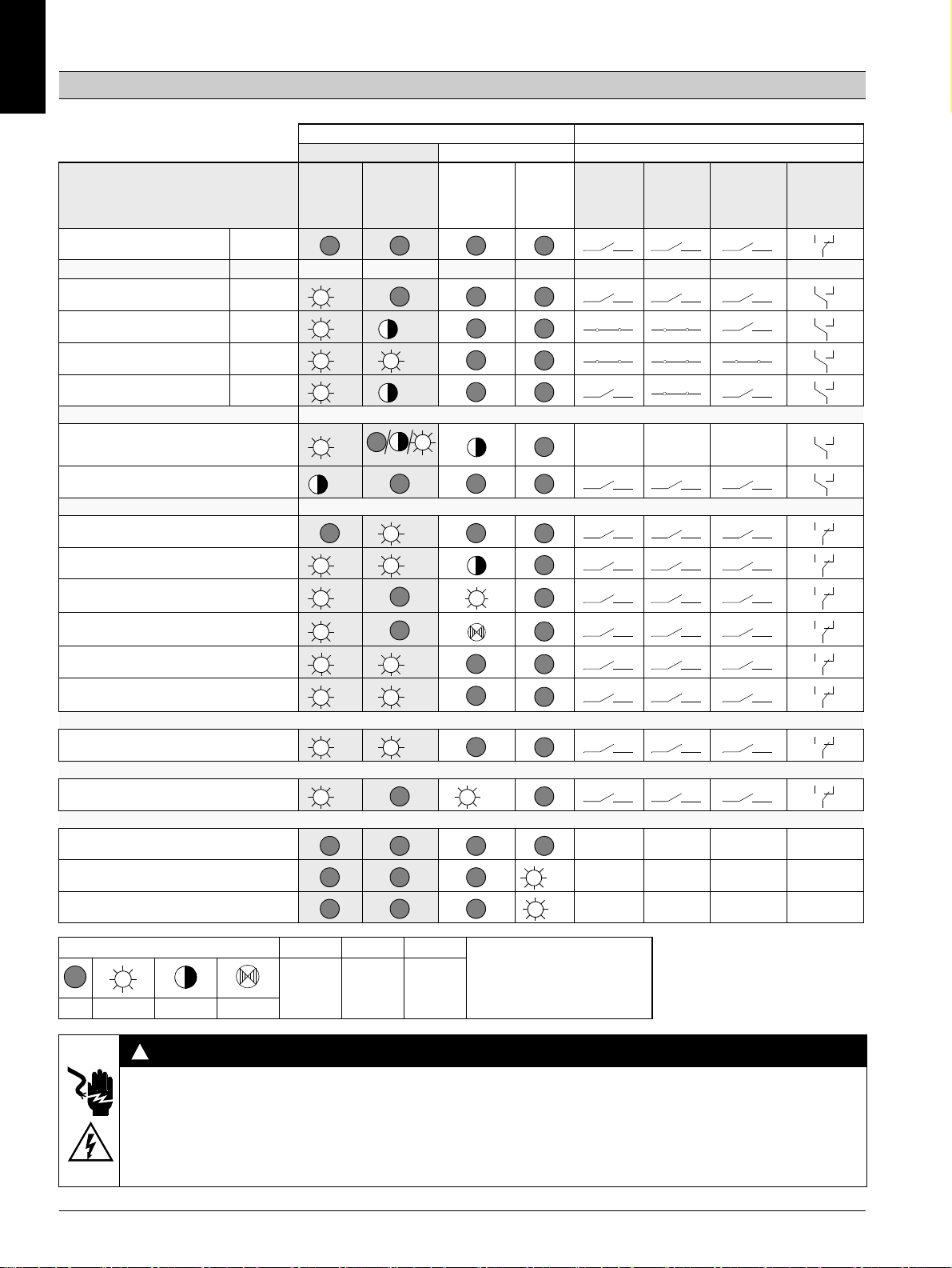
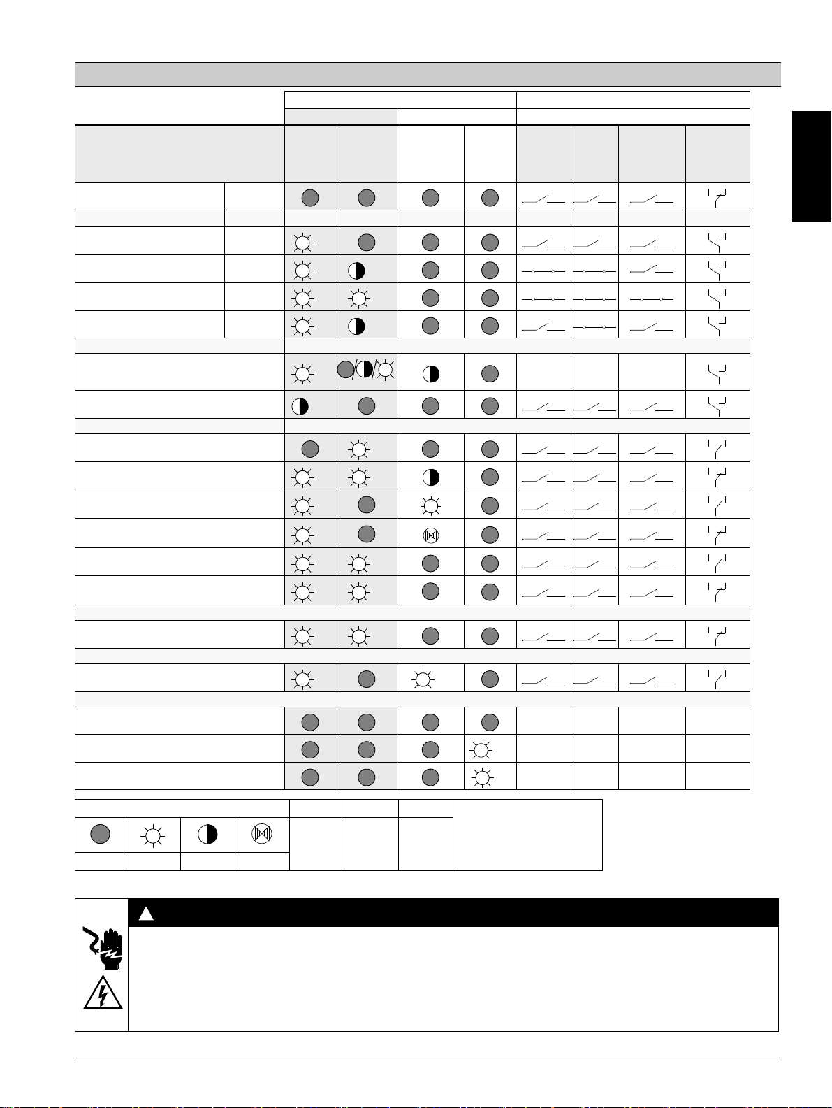
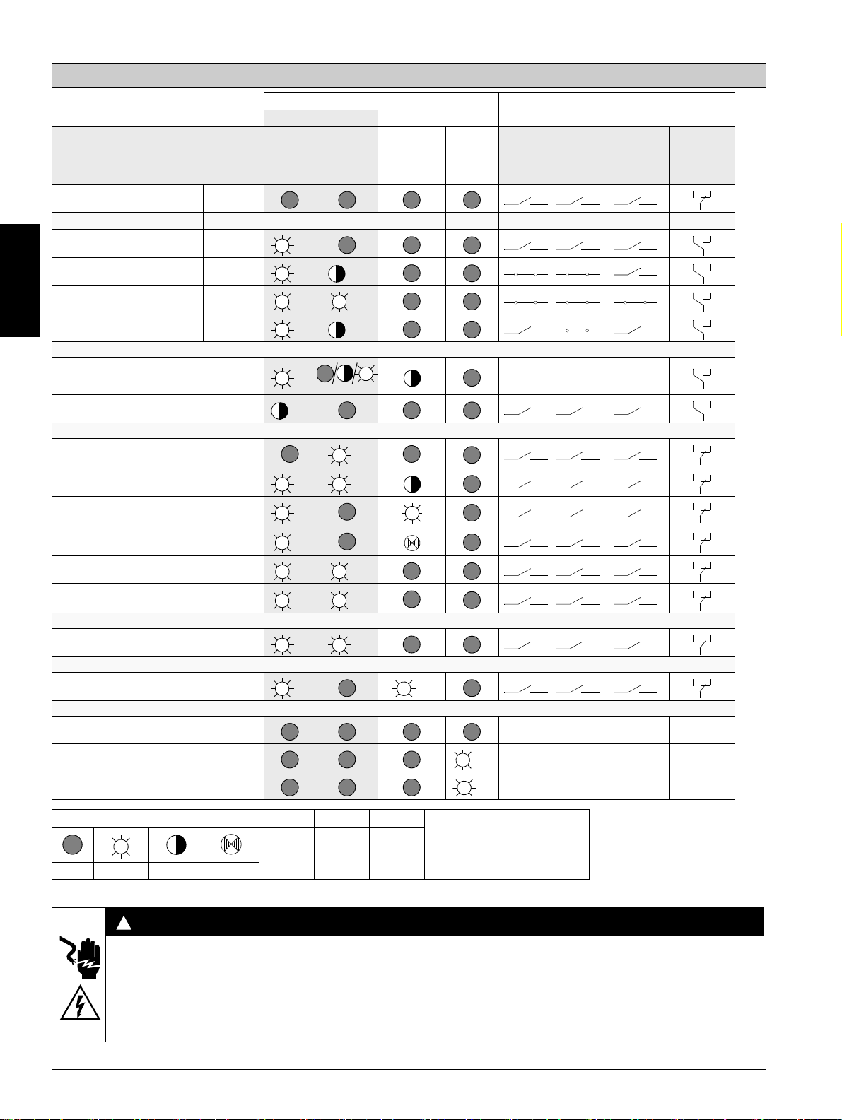
Anzeigenübersicht
3RW40
U
= 0
s
Betriebszustand
Aus
LED-Anzeigen 3RW40 Hilfskontakte
Sanftstarter Motorschutz
STATE /
DEVICE
(rd/gn/ylw)
BYPASSED /
FAILURE
(gn/rd))
OVERLOAD
(rd)
RESET
MODE
(ylw/gn)
13 14
(ON)
13 14
(RUN)
24 23
(BYPASSED)
96 95 98
FAILURE /
OVERLOAD
IN
0
Anlauf
Bypassed
Auslauf
Warnung
Ie/Class-Einstellung unzulässig
Start gesperrt, Gerät zu warm
Fehler
Versorgungsspannung Elektronik unzulässig
unzulässige Ie/Class-Einstellung und IN (0 -> 1)
Motorschutzabschaltung
Überlastrelais / Thermistor
Thermistormotorschutz
Drahtbruch / Kurzschluss
Thermische Überlastung Gerät
- fehlende Lastspannung
- Phasenausfall, fehlende Last
Gerätefehler
Testfunktion
1)
TEST t > 5 s drücken
RESET MODE (Drücken zum Wechseln)
Manual Reset
1
1
0
Auto Reset
Remote Reset siehe Bild 6.2
Anzeige der LEDs
gn
=
ylw
=
rd
1)
Test Motorschutzabschaltung
=
aus ein blinkend flimmernd grün gelb rot
WARNUNG
Automatischer Wiederanlauf.
Kann zu Tod, schwerer Körperverletzung oder Sachbeschädigung führen.
Der automatische Rücksetzmodus (RESET MODE) darf nicht in Anwendungen verwendet werden, in denen der unerwartete Neustart
des Motors nach Ablauf der Wiederbereitschaftszeit zu Personen- oder Sachschäden führen kann.
Der Startbefehl (z. B. durch die SPS) muss vor einem Resetbefehl zurückgesetzt werden, da bei anstehendem Startbefehl nach dem
Resetbefehl automatisch ein erneuter, selbsttätiger Wiederanlauf erfolgt. Dies gilt insbesondere bei Motorschutzauslösung. Aus
Sicherheitsgründen wird empfohlen, den Sammelfehlerausgang (Klemmen 95 und 96) in die Steuerung einzubinden.
4 3ZX1012-0RW40-2DA1
Page 5
Soft starter 3RW40 2, 3RW40 3, 3RW40 4 English
!
!
1
1
3
5
2
4
6
a
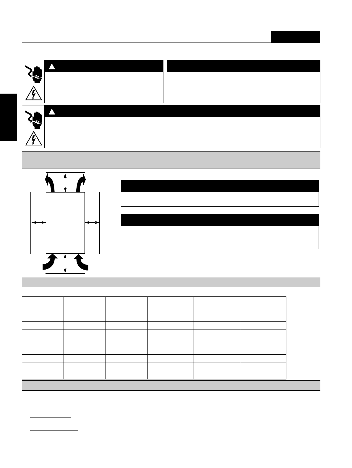
≥ 60 mm
[≥ 2.36 in]
≥ 40 mm
[≥ 1.56 in]
NOTICE
Please adhere to the specified spacings when installing the device so that sufficient air can
circulate for ventilation. The unit is ventilated from bottom to top.
CAUTION
Risk of damage to property.
Ensure that no liquids, dust or conductive parts enter the soft starter.
NOTE
Surrounding air temperature - A rating assigned to open type equipment that refers to the
maximum ambient temperature of air immediately surrounding the equipment inside of the
ultimate enclosure.
a
a) 3RW40 2: 15 mm [0.59 in]
3RW40 3; 3RW40 4: 30 mm [1.18 in]
Read and understand these instructions before installing, operating, or maintaining the equipment.
DANGER
CAUTION
Hazardous voltage.
Will cause death or serious injury.
Turn off and lock out all power supplying this device
Reliable functioning of the equipment is only ensured with certified
components.
before working on this device.
DANGER
Hazardous voltage.
Will cause death or serious injury.
The terminals of the motor control device must not be touched when it is connected to a voltage in order to prevent electrical shocks or
burning. The output terminals of the motor control device are connected to a voltage even when it is in the OFF state.
Stand-alone installation spacings (see soft starter manual for side-by-side installation)
English
Setpoint values for motor current
Permitted setpoint values for the motor current, dependent on the CLASS setting at 40 °C surrounding air temperature
Ie [A] I
3RW40 24-... 12.5 5 12.5 11 10
3RW40 26-... 25.3 10.3 25.3 23 21
3RW40 27-... 32.2 17.2 32.2 30 27
3RW40 28-... 38 23 38 34 31
3RW40 36-... 45 22.5 45 42 38
3RW40 37-... 63 25.5 63 50 46
3RW40 38-... 72 34.5 72 56 50
3RW40 46-... 80 42.5 80 70 64
3RW40 47-... 106 46 106 84 77
Programming the ON/RUN output 13/14 (factory setting: ON) (Fig. 3 in graphics section)
1. Start programming mode: (For the 3RW40 2 device, remove the cover as shown in Figure 2.) Press and hold the "RESET MODE" button (2) for
longer than 2 seconds until the LED "DEVICE" (5) flickers green. While pushing the "RESET MODE" button (2), press the "RESET/TEST" button
2. Display mode:
(1) for longer than 1 second until the LED "DEVICE" (5) on the device lights up red.
LED "STATE/BYPASSED/FAILURE" (6) flashes green: ON mode. LED "STATE/BYPASSED/FAILURE" (6) flickers green: RUN
mode.
3. Change mode:
4. Exit programming mode and save settings: Press and hold the "RESET/TEST" button (1) for longer than 1 second until the LED "DEVICE" (5)
lights up green.
3ZX1012-0RW40-2DA1 5
Press the "RESET MODE" (2) button.
[A] I
min
[A] CLASS 10 I
max
[A] CLASS 15 I
max
[A] CLASS 20
max
Page 6
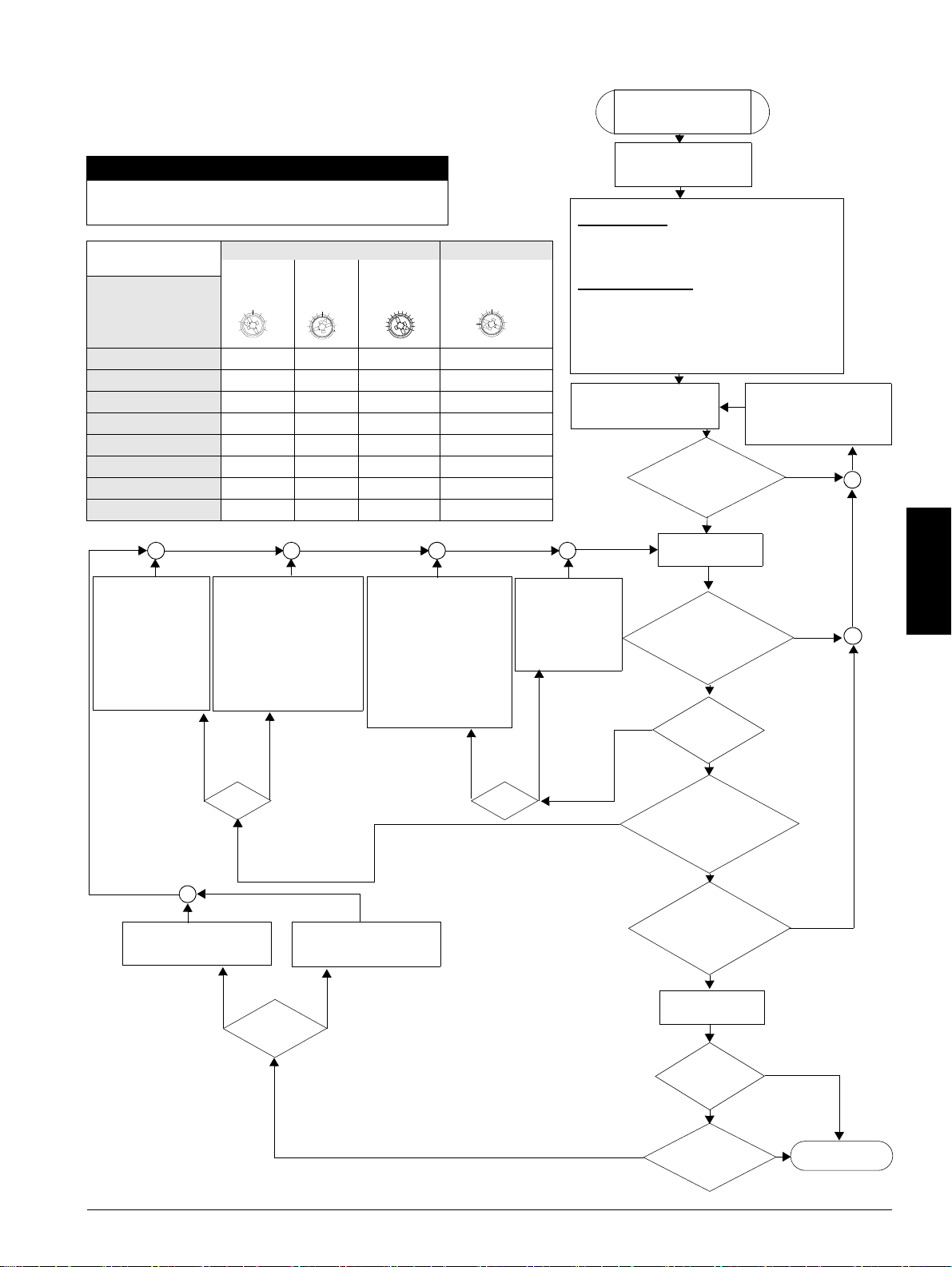
Quick commissioning instructions
1. Switch off soft starter
(IN 1 -> 0).
2. Reduce startup time (turn
potentiometer anticlockwise).
or
3. Increase limit value if the
current limit is set (turn
potentiometer clockwise).
1. Switch soft starter
off (IN 1 -> 0).
2. Increase startup
time (turn potentiometer clockwise).
3. Reduce current limit
value (turn
potentiometer anticlockwise).
1. Switch off soft starter
(IN 1 -> 0).
2. Increase start voltage
(turn potentiometer
clockwise)
or
3. Increase limit value if the
current limit is set (turn
potentiometer clockwise).
1. Switch soft starter
off (IN 1 -> 0).
2. Reduce start
voltage (turn
potentiometer anticlockwise).
The motor reaches
its nominal rotational
speed
- with a torque
increase that is too
high
- faster than desired,
with a startup
current that is too
high
The motor reaches
its nominal
rotational speed
- slower than
desired
- not at all
(motor stuck)
The motor
hums and
does not
start
immediately
Motor:
The motor
starts with a
sudden
increase in
torque
Increase stopping time (turn
potentiometer clockwise)
Reduce stopping time (turn
potentiometer anticlockwise)
Soft stopping
The motor stops
abruptly and not
softly.
The motor keeps
going for too long.
Quick commissioning of
the 3RW40 SIRIUS
soft starter
1. Wiring control
- Control part and
- Performance part
2. Configure device
Motor protection
- Set the rated motor current of the device using the Ie
controller
- Set the required tripping class with the CLASS switch.
Set the soft start function
- Current limit value (x Ie)
- Startup time (s)
- Start voltage (%)
- Stopping time (s)
to the desired value (see table for suggested settings).
3. Check and connect the
voltages in the control and
main circuits.
Determine and rectify the
cause of the fault using the
LED display and the status
table (see Page 7).
"DEVICE" LED
cont. green light,
are the other LEDs
off?
No
4. Switch soft starter
on (IN 0 -> 1)
LEDs:
"DEVICE" cont. green
light, "STATE/BYPASSED"
flashing green?
Does
the motor
start softly?
Does
the motor reach
its nominal rotational speed
quickly and within the
desired time?
LEDs:
"DEVICE" cont. green light,
"STATE/BYPASSED" green
cont. light?
Switch soft starter
off (IN 1 -> 0)
Which type of
stopping has been
selected?
Motor
reaches stationary
state as desired?
End of
commissioning
Motor:
No
No
No
No
No
Thermistor connection (3RW40.-.TB0. only)
– Thermoclick connection according to Fig. 6.3 (remove jumper)
– PTC connection type A according to Fig. 6.4 (remove jumper)
CAUTION
Risk of damage to property.
Connection to an unassigned terminal is not permitted.
Suggested setting Startup parameters
Stopping
parameters
Start
voltage %
Startup
time s
Current limit
value
Stopping time s
Application
Conveyor belt
70 10
5xI
e
5
Roller conveyor
60 10
5xI
e
5
Compressor
50 10
4xI
e
0
Small fan
40 10
4xI
e
0
Pumps
40 10
4xI
e
10
Hydraulic pump
40 10
4xI
e
0
Stirrers
40 20
4xI
e
0
Milling machines
40 20
4xI
e
0
40
100%
0
5
10
20s
e
xI
5
1.3
5
10
0
20s
Soft stopping
Yes
Yes
Yes
Yes
Yes
Yes
Yes
Yes
Coasting down
English
6 3ZX1012-0RW40-2DA1
Page 7
Display overview
gn
gngngn
gn
gngngn
gn gn
ylw
rd
gn
rd
gngnylw
rd
gnrdrdrdgn
rd
ylw
gn
!
3RW40
U
= 0
s
Operating state
OFF
LED displays on 3RW40 Auxiliary contacts
Soft starter Motor protection
DEVICE
(rd/gn/ylw)
STATE /
BYPASSED
/ FAILURE
(gn/rd)
OVERLOAD
(rd)
RESET
MODE
(ylw/gn)
13 14
(ON)
13 14
(RUN)
24 23
(BYPASSED)
96 95 98
FAILURE /
OVERLOAD
English
IN
0
Start-up
Bypassed
Run-out
Warning
Ie / class setting invalid
Start-up locked, device too warm
Error
Supply voltage electronics invalid
Invalid Ie / class setting and IN (0 -> 1)
Motor protection switch-off
Overload relay / thermistor
Thermistor motor protection
Wire break / short circuit
Thermal overload device
- Missing load voltage
- Phase failure, no load
Device fault
Test function
1)
Press TEST for t > 5 s
RESET MODE (press to change)
Manual Reset
1
1
0
Auto Reset
Remote Reset see Fig. 6.2
LED display
gn
=
ylw
rd
1)
=
Motor protection shutdown test
=
OFF ON flashing flickering green yellow red
WARNING
Automatic restart.
May result in death, serious injury or damage to property.
The automatic reset mode (RESET MODE) must not be used in applications where an unexpected restart of the motor after the
recovery time has elapsed may lead to personal injury or damage to property.
The start command (e.g. by the PLC) must be reset before a reset command, since an automatic restart is executed when a start
command is pending after the reset command. This especially applies to motor protection tripping. For safety reasons it is
recommended to integrate the group fault output (terminals 95 and 96) into the control.
3ZX1012-0RW40-2DA1 7
Page 8
Démarreur progressif 3RW40 2, 3RW40 3, 3RW40 4 Français
!
!
1
1
3
5
2
4
6
a
≥ 60 mm
[≥ 2.36 in]
≥ 40 mm
[≥ 1.56 in]
IMPORTANT
Veuillez respecter au montage de l’appareil les distances indiquées pour assurer une circulation
suffisante de l’air de refroidissement. L’appareil est ventilé du bas vers le haut.
PRUDENCE
Risque de dommages matériels.
Veillez à ce que ni liquide, ni poussière ou objet conducteur ne puisse pénétrer dans le
démarreur progressif.
a
a) 3RW40 2 : 15 mm [0.59 in]
3RW40 3 ; 3RW40 4 : 30 mm [1.18 in]
Ne pas installer, utiliser ou intervenir sur cet équipement avant d'avoir lu et assimilé les présentes instructions et notamment les
conseils de sécurité et mises en garde qui y figurent.
DANGER
PRUDENCE
Tension dangereuse.
Danger de mort ou risque de blessures graves.
Mettre hors tension avant d’intervenir sur l’appareil.
La sécurité de fonctionnement de l'appareil n'est garantie qu'avec des
composants certifiés.
Français
DANGER
Tension dangereuse.
Danger de mort ou risque de blessures graves.
Il est interdit de toucher les bornes du bloc de commande du moteur lorsque l’appareil est sous tension pour éviter les chocs
électriques ou les brûlures. Une tension est présente aux bornes de sortie même à l’ARRET du bloc de commande du moteur.
Distances de montage pour installation séparée (installation juxtaposée, voir le manuel Démarreurs
progressifs)
Valeurs de réglage du courant du moteur
Valeurs de réglage du courant du moteur admissible en fonction du CLASS à une température ambiante de 40° C
Ie [A] I
3RW40 24-... 12,5 5 12,5 11 10
3RW40 26-... 25,3 10,3 25,3 23 21
3RW40 27-... 32,2 17,2 32,2 30 27
3RW40 28-... 38 23 38 34 31
3RW40 36-... 45 22,5 45 42 38
3RW40 37-... 63 25,5 63 50 46
3RW40 38-... 72 34,5 72 56 50
3RW40 46-... 80 42,5 80 70 64
3RW40 47-... 106 46 106 84 77
Programmation de la sortie ON/RUN 13/14 (réglage standard : ON) (partie graphique, figure 3)
1. Lancement de la programmation : (retirez tout d’abord le couvercle de l’appareil 3RW40 2 comme le montre la figure 2.) Appuyez sur la touche
"RESET MODE" (2) pendant plus de 2 secondes jusqu’à ce que la LED verte "DEVICE" (5) scintille. Maintenez la touche "RESET MODE" (2)
appuyée et pressez la touche "RESET/TEST" (1) pendant plus d’1 s, jusqu’à ce que la LED rouge "DEVICE" (5) scintille sur l’appareil.
2. Affichage du mode :
scintille : mode RUN.
3. Changement de mode : appuyez sur la touche "RESET MODE" (2).
4. Fin de la programmation et enregistrement des réglages :
LED verte "DEVICE" (5) s’allume.
8 3ZX1012-0RW40-2DA1
la LED verte "STATE/BYPASSED/FAILURE" (6) clignote : mode ON. La LED verte "STATE/BYPASSED/FAILURE" (6)
[A] I
min
[A] CLASS 10 I
max
[A] CLASS 15 I
max
[A] CLASS 20
max
appuyez sur la touche "RESET/TEST" (1) pendant plus d’1 seconde jusqu’à ce que la
Page 9
Instructions de mise en service rapide
1. Arrêt du démarreur
progressif (IN 1 -> 0).
2. Réduire le temps de
démarrage (potentiomètre
vers la gauche)
ou
3. Augmenter la valeur de
limitation si réglage de
limitation de courant
(potentiomètre vers la droite).
1. Arrêt du démarreur
progressif (IN 1 -> 0).
2. Allonger le temps de
démarrage
(potentiomètre
vers la droite).
3. Réduire la valeur de
limitation de courant
(potentiomètre vers la
gauche).
1. Arrêt du démarreur
progressif (IN 1 -> 0).
2. Augmenter la tension de
démarrage (potentiomètre
vers la droite)
ou
3.Augmenter la valeur de
limitation si réglage de
limitation de courant
(potentiomètre vers la
droite).
1. Arrêt du démarreur
progressif (IN 1 -> 0).
2. Réduire la tension
de démarrage
(potentiomètre vers
la gauche)
Le moteur atteint sa
vitesse nominale
- avec une montée
de couple trop
rapide
- plus rapidement
que souhaité, avec
un courant de
démarrage trop fort
Le moteur atteint
sa vitesse
nominale
- plus lentement
que souhaité,
- pas du tout
(s'arrête)
Le moteur ne
démarre pas
immédiatement
et ronfle
Moteur
:
Le moteur
démarre
avec choc de
couple
Allonger le temps de
ralentissement
(potentiomètre vers la droite)
Réduire le temps de
ralentissement
(potentiomètre vers la gauche)
Ralentissement
progressif
Le moteur s'arrête de
manière abrupte et
non progressive.
Le moteur poursuit
sa marche encore
trop longtemps.
Mise en service rapide
3RW40 SIRIUS
démarreur progressif
1. Contrôle du câblage
- bloc de commande et
- bloc de puissance
2. Paramétrage de l’appareil
Protection moteur
- sur régleur Ie régler le courant assigné du moteur
- régler la classe de coupure nécessaire sur le commutateur
CLASS.
Fonction démarreur progressif
- valeur limitation de courant (x Ie)
- temps démarrage (s)
- tension de démarrage (%)
- temps de ralentissement (s)
à régler sur les valeurs souhaitées (voir le tableau Proposition
de réglage).
3. Contrôler et mettre en circuit
les tensions dans le circuit
principal et de commande.
Déterminer et supprimer
l’origine du défaut via
l’affichage LED et la table des
états.
(voir Page 10)
LED "DEVICE"
feu fixe vert,
les autres LED
sont éteintes ?
non
4. Mettre en marche
le démarreur
progressif (IN 0 -> 1)
LED :
"DEVICE" feu fixe
vert, "STATE/BYPASSED"
vert clignotant ?
Moteur en
marche progressive-
ment ?
Le moteur
atteint rapidement,
sa vitesse nominale dans le
temps souhaité ?
LED :
"DEVICE" feu
vert fixe, "STATE/
BYPASSED" feu
vert fixe ?
Arrêt du démarreur
progressif (IN 1 -> 0)
Quel mode
de ralentissement
sélectionné ?
Le moteur
s’arrête comme
prévu ?
Mise en service
achevée
Moteur :
non
non
non
non
non
Raccordement de thermistance (uniquement 3RW40.-.TB0.)
– Raccordement du thermoclick selon la figure 6.3 (retirer les ponts à fil)
– Raccordement PTC type A selon la figure 6.4 (retirer les ponts à fil)
PRUDENCE
Risque de dommages matériels.
Un raccordement aux bornes libres est inadmissible.
Proposition de réglage Paramètres de démarrage
Paramètres de
ralentissement
Tension
démarrage %
Te mp s
dém. s
Val. limitation
courant
Temps ralent. s
Application
Convoyeur
70 10
5xI
e
5
Convoyeur à rouleaux
60 10
5xI
e
5
Compresseur
50 10
4xI
e
0
Petit ventilateur
40 10
4xI
e
0
Pompe
40 10
4xI
e
10
Pompe hydraulique
40 10
4xI
e
0
Malaxeur
40 20
4xI
e
0
Fraiseuse
40 20
4xI
e
0
40
100%
0
5
10
20s
e
xI
5
1.3
5
10
0
20s
Ralentissement progressif
oui
oui
oui
oui
oui
oui
oui
oui
Ralentissement naturel
Français
3ZX1012-0RW40-2DA1 9
Page 10
Vue d’ensemble des affichages
gn
gngngn
gn
gngngn
gn
gn
ylw
rd
gnrdgn
gn
ylw
rd
gnrdrdrdgn
rd
ylw
gn
!
3RW40
U
= 0
c
Etat de fonctionnement
Français
Arrêté
LED de signalisation 3RW40 Contacts auxiliaires
Démarreur progressif Protection moteur
STATE /
DEVICE
(rd/gn/ylw)
BYPASSED
/ FAILURE
(gn/rd))
OVERLOAD
(rd)
IN
0
RESET
MODE
(ylw/gn)
13 14
(ON)
13 14
(RUN)
24 23
(BYPASSED)
96 95 98
FAILURE /
OVERLOAD
Démarrage
Bypassed
Ralentissement
Alarme
Réglage Ie/Class incorrect
Démarrage bloqué, appareil trop chaud
Défauts
Tension d’alimentation de l’électronique
incorrecte
Réglage Ie/Class incorrect et IN (0 -> 1)
Coupure du moteur par protection
Relais de surcharge / thermistance
Protection des moteurs par thermistance
Rupture de câble / court-circuit
Surcharge thermique appareil
- manque de tension de charge
- coupure de phase, charge non raccordée
Défaut sur l’appareil
Fonction de test
1)
Appuyer sur TEST t > 5 s
RESET MODE (appuyer pour changer)
Reset manuel
1
1
0
Reset automatique
Reset à distance voir la figure 6.2
Affichage des LED
gn
=
éteinte allumée clignotante scintillante verte jaune rouge
ylw
rd
1)
=
Test Coupure protection moteur
=
ATTENTION
Redémarrage automatique.
Peut causer la mort, des lésions graves ou des dommages matériels.
Le réarmement automatique (RESET MODE) ne peut être utilisé dans des applications où le redémarrage inattendu du moteur après
le temps du récupération peut provoquer des lésions ou des dommages matériels importants. L’ordre de marche (de l’API par ex.) doit
être annulé avant de donner l’ordre de réarmement ; en effet, la présence de l’ordre de marche à la suite du réarmement donne lieu à
un redémarrage automatique. Ceci vaut tout particulièrement pour le déclenchement de protection du moteur. Pour des raisons de
sécurité, il est recommandé d’intégrer la sortie de signalisation de défauts groupés (bornes 95 et 96) à la commande.
10 3ZX1012-0RW40-2DA1
Page 11

Arrancador suave 3RW40 2, 3RW40 3, 3RW40 4 Español
!
!
1
1
3
5
2
4
6
a
≥ 60 mm
[≥ 2.36 in]
≥ 40 mm
[≥ 1.56 in]
ATENCIÓN
Al instalar el equipo, obsérvese las distancias mínimas indicadas para garantizar la circulación
del aire necesario para la refrigeración. La ventilación del equipo se realiza desde abajo hacia
arriba.
PRECAUCIÓN
¡Peligro de daños materiales!
Preste atención de que no pueda ingresar líquido, polvo o algún objeto conductor al interno del
arrancador suave.
a
a) 3RW40 2: 15 mm [0.59 in]
3RW40 3; 3RW40 4: 30 mm [1.18 in]
1
1
3
5
2
4
6
Leer y comprender este instructivo antes de la instalación, operación o mantenimiento del equipo.
PELIGRO
PRECAUCIÓN
Tensión peligrosa.
Puede causar la muerte o lesiones graves.
Desconectar la alimentación eléctrica antes de trabajar en el equipo.
El funcionamiento seguro del aparato sólo está garantizado
con componentes certificados.
PELIGRO
Tensión peligrosa.
Puede causar la muerte o lesiones graves.
Para evitar todo riesgo de electrocución o de quemaduras, no tocar los bornes de la unidad de control del motor mientras estén bajo
tensión. Los bornes de salida están bajo tensión aunque la unidad de control del motor esté desconectada.
Distancias de montaje para instalación simple (para instalación junto a otros aparatos, ver manual
arrancadores suaves)
Español
Valores de ajuste de la corriente del motor
Valores de ajuste admisibles de la corriente del motor en función del tipo CLASS a temperaturas ambiente de 40° C
Ie [A] I
3RW40 24-... 12,5 5 12,5 11 10
3RW40 26-... 25,3 10,3 25,3 23 21
3RW40 27-... 32,2 17,2 32,2 30 27
3RW40 28-... 38 23 38 34 31
3RW40 36-... 45 22,5 45 42 38
3RW40 37-... 63 25,5 63 50 46
3RW40 38-... 72 34,5 72 56 50
3RW40 46-... 80 42,5 80 70 64
3RW40 47-... 106 46 106 84 77
Programación de la salida ON/RUN 13/14 (ajuste de fábrica: ON) (parte de gráficas, figura 3)
1. Iniciar programación: (Al usar el equipo 3RW40 2, retire primero la tapa como demostrado en la figura 2.) Mantenga pulsada la tecla " RESET
MODE" (2) durante más de 2 s, hasta que el LED "DEVICE" (5) parpadee en verde. Mantenga pulsada la tecla "RESET MODE" (2), pulsando al
mismo tiempo la tecla "RESET/TEST" (1) durante más de 1 s, hasta que el LED "DEVICE" (5) del equipo se ilumine rojo.
2. Indicar modo:
el LED "STATE/BYPASSED/FAILURE" (6) destella verde: modo ON. El LED "STATE/BYPASSED/FAILURE" (6) parpadea en
verde: modo RUN.
3. Cambiar modo:
pulse la tecla "RESET MODE" (2).
4. Terminar programación y guardar ajustes: mantenga pulsada la tecla " RESET/TEST" (1) durante más de 1 s, hasta que el LED "DEVICE" (5)
se ilumine verde.
[A] I
min
[A] CLASS 10 I
max
[A] CLASS 15 I
max
[A] CLASS 20
max
3ZX1012-0RW40-2DA1 11
Page 12

Instrucciones para la puesta en servicio rápida
1. Desactivar el arrancador
suave (IN 1 -> 0).
2. Reducir el tiempo de
arranque (girar potenciómetro
hacía la izquierda)
o bien
3. aumentar el valor límite en
el caso de funcionamiento
con limitación de corriente
(girar potenciómetro hacía la
derecha).
1. Desactivar el
arrancador suave (IN 1
-> 0).
2. Aumentar el tiempo
de arranque (girar
potenciómetro hacía la
derecha).
3. Reducir el valor
límite de corriente
(girar potenciómetro
hacía la izquierda).
1. Desactivar el arrancador
suave (IN 1 -> 0).
2. Aumentar la tensión de
arranque (girar potenciómetro
hacía la derecha)
o bien
3. aumentar el valor límite en
el caso de funcionamiento con
limitación de corriente (girar
potenciómetro hacía la
derecha).
1. Desactivar el
arrancador suave
(IN 1 -> 0).
2. Reducir la tensión
de arranque (girar
potenciómetro hacía
la izquierda)
El motor alcanza su
velocidad nominal
- con una subida del
momento de giro
demasiado elevada
- más rápido de lo
deseado,
con una corriente
de arranque
demasiado
elevada
El motor alcanza su
velocidad nominal
- más lento de lo
deseado,
- de ninguna
manera
(queda bloqueado)
El motor no
arranca
inmediatamente
y zumba
Motor:
El motor
arranca con
golpe
instantáneo
Aumentar el tiempo de deceleración
(girar potenciómetro hacía la derecha)
Reducir el tiempo de deceleración (girar
potenció-metro hacía la izquierda)
Deceleración
suave
El motor queda
parado de manera
abrupta, no suave.
El motor sigue
funcionando por
un periodo
demasiado largo.
Puesta en servicio rápida
3RW40 SIRIUS
Arrancador suave
1. Control del cableado
- parte de control y
- parte de potencia
2. Parametrizar el equipo
Protección del motor
- ajustar la corriente nominal del motor mediante el ajustador I
e
- seleccionar la clase de disparo mediante el selector CLASS
Función de arranque suave
- Valor límite de corriente(x I
e
)
- Tiempo de arranque (s)
- Tensión de arranque (%)
- Tiempo de parada (s)
ajustar los valores deseados (ver tabla Parámetros
recomendados).
3. Controlar y aplicar tensiones
en el circuito de mando y en el
circuito principal.
Determinar y eliminar la
causa del fallo mediante el
indicador LED y la tabla de
estado. (ver Página 13)
LED "DEVICE"
luz verde permanente,
¿están apagados los
demás LEDs ?
no
4. Activar el arrancador suave (IN 0 -> 1)
LEDs:
"DEVICE" luz verde
permanente,
"STATE/BYPASSED"
¿destella en
verde?
¿arranca el motor
suavemente?
¿El motor
alcanza rápidamente,
dentro del tiempo deseado,
su velocidad
nominal?
LEDs:
¿"DEVICE" luz verde,
permanente, "STATE/
BYPASSED" luz verde
permanente?
Desactivar el arrancador suave (IN 1 -> 0)
¿Cuál es el
tipo de deceleración
seleccionado?
¿Para el motor
como deseado?
Puesta en servicio
finalizada
Motor:
no
no
no
no
no
Entrada de termistor (sólo 3RW40.-.TB0.)
– Conexión Thermoclick según figura 6.3 (quitar ligadura de alambre)
– Conexión PTC de tipo A según figura 6.4 (quitar ligadura de alambre)
PRECAUCIÓN
¡Peligro de daños materiales!
No está admitida la conexión con bornes no ocupados.
Parámetros
recomendados
Parámetros de arranque
Parámetros de
parada
Tensión de
arranque %
Tiempo de
arranque s
Valor límite
de corriente
Tiempo de parada s
Aplicación
Cinta transportadora
70 10
5xI
e
5
Transportador a rodillos
60 10
5xI
e
5
Compresor
50 10
4xI
e
0
Ventilador pequeño
40 10
4xI
e
0
Bomba
40 10
4xI
e
10
Bomba hidráulica
40 10
4xI
e
0
Mezcladora
40 20
4xI
e
0
Máquina fresadora
40 20
4xI
e
0
40
100%
0
5
10
20s
e
xI
5
1.3
5
10
0
20s
Deceleración suave
sí
sí
sí
sí
sí
sí
sí
sí
Deceleración natural
Español
12 3ZX1012-0RW40-2DA1
Page 13

Resumen de las indicaciones
gn
gngngn
gn
gn
gn
gn
gn gn
ylw
rd
gn
rd
gn
gn
ylw
rd
gnrdrd
rdgnrd
ylw
gn
!
3RW40
U
= 0
s
Estado operativo
Desconectado
Indicadores LED 3RW40 Contactos auxiliares
Arrancador suave Protección del motor
DEVICE
(rd/gn/ylw)
STATE /
BYPASSED
/ FAILURE
(gn/rd))
OVERLOAD
(rd)
RESET
MODE
(ylw/gn)
13 14
(ON)
13 14
(RUN)
24 23
(BYPASSED)
96 95 98
FAILURE /
OVERLOAD
IN
0
Arranque
Bypassed
Deceleración
Alarma
Ajuste Ie/Class inadmisible
Arranque bloqueado, sobrecalentamiento del equipo
Fallo
Tensión de alimentación de la electrónica inadmisible
Ajuste Ie/Class inadmisible e IN (0 -> 1)
Desconexión protección del motor
Relé de sobrecarga / termistor
Protección del motor del termistor
Rotura de cable / cortocircuito
Sobrecarga térmica del equipo
- Falta tensión de carga
- Corte de fase, falta carga
Fallo del equipo
Función de prueba
1)
Pulsar TEST t > 5 s
RESET MODE (pulsar para cambiar)
Reset manual
1
1
0
Español
Reset automático
Reset remoto ver figura 6.2
Indicación de los LEDs
gn
=
Apagado Encendido Intermitente Centelleante verde amarillo rojo
ylw
rd
1)
=
Test desconexión protección motor
=
ADVERTENCIA
Rearranque automático.
Puede causar la muerte, lesiones graves o daños materiales.
No está permitido utilizar el modo automático de Reset (RESET MODE) en aplicaciones en las cuales el rearranque imprevisto
después del tiempo de recuperación pueda provocar lesiones físicas o daños materiales. La orden de marcha (p. ej. por medio de la
PLC) deberá anularse antes de una orden de rearme; en efecto, la presencia de la orden de marcha después de la orden de rearme
provoca un rearranque automático. Esto es especialmente válido para el disparo de protección del motor. Por razones de seguridad se
recomienda integrar la salida de señalización de fallo agrupado (bornes 95 y 96) en la unidad de control.
3ZX1012-0RW40-2DA1 13
Page 14

Avviatore dolce 3RW40 2, 3RW40 3, 3RW40 4 Italiano
!
!
1
1
3
5
2
4
6
a
≥ 60 mm
[≥ 2.36 in]
≥ 40 mm
[≥ 1.56 in]
ATTENZIONE
Durante il montaggio osservare le distanze indicate per consentire una circolazione sufficiente
di aria di raffreddamento. L'apparecchio viene ventilato dal basso verso l'alto.
CAUTELA
Pericolo di danni alle cose.
Evitare che liquidi, polvere o altri conduttori finiscano nell'avviatore dolce.
a
a) 3RW40 2: 15 mm [0.59 in]
3RW40 3; 3RW40 4: 30 mm [1.18 in]
Leggere con attenzione queste istruzioni prima di installare, utilizzare o eseguire manutenzione su questa apparecchiatura.
PERICOLO
CAUTELA
Tensione pericolosa.
Può provocare morte o lesioni gravi.
Scollegare l’alimentazione prima di eseguire interventi
Il funzionamento sicuro dell'apparecchiatura è garantito soltanto con
componenti certificati.
sull'apparecchiatura.
PERICOLO
Tensione pericolosa.
Può provocare morte o lesioni gravi.
Per evitare folgorazioni o ustioni, i morsetti dell'avviatore non devono essere toccati quando l'apparecchiatura è sotto tensione. I
morsetti di uscita sono sotto tensione anche quando l'avviatore è disinserito.
Distanze di montaggio nell'installazione singola (per l'installazione compatta vedi manuale avviatore dolce)
Italiano
Valori di impostazione della corrente motore
Valori di impostazione della corrente motore a seconda del tipo di CLASS a 40° C temperatura ambiente
Ie [A] I
3RW40 24-... 12,5 5 12,5 11 10
3RW40 26-... 25,3 10,3 25,3 23 21
3RW40 27-... 32,2 17,2 32,2 30 27
3RW40 28-... 38 23 38 34 31
3RW40 36-... 45 22,5 45 42 38
3RW40 37-... 63 25,5 63 50 46
3RW40 38-... 72 34,5 72 56 50
3RW40 46-... 80 42,5 80 70 64
3RW40 47-... 106 46 106 84 77
Programmazione dell'uscita ON/RUN 13/14 (impostazione di fabbrica: ON) (grafiche, figura 3)
1. Avvio della programmazione: (nell'apparecchio 3RW40 2, rimuovere prima la copertura come indicato nella Figura 2.) Tenere premuto il tasto
"RESET MODE" (2) per più di 2 secondi. Il LED "DEVICE" (5) verde sfarfalla. Tenere premuto il tasto "RESET MODE" (2) e premere allo stesso
tempo il tasto "RESET/TEST" (1) per più di 1 secondo. Il LED "DEVICE" (5) rosso dell'apparecchio si illumina.
2. Indicazione del modo:
verde: modo RUN.
3. Cambio del modo:
4. Fine della programmazione e salvataggio delle impostazioni: tenere premuto il tasto "RESET/TEST" (1) per più di 1 secondo. Il LED "DEVICE"
(5) verde illumina.
il LED "STATE/BYPASSED/FAILURE" (6) lampeggia verde: modo ON. Il LED "STATE/BYPASSED/FAILURE" (6) sfarfalla
premere il tasto "RESET MODE" (2).
[A] I
min
[A] CLASS 10 I
max
[A] CLASS 15 I
max
[A] CLASS 20
max
14 3ZX1012-0RW40-2DA1
Page 15
Istruzioni per messa in servizio rapida
1. Disattivare avviatore dolce
(IN 1 -> 0).
2. Ridurre il tempo di
avviamento (girare il potenziometro verso sinistra)
oppure
3. se la lim. di corrente è
impostata, aumentare il valore
di limitazione (girare il
potenziometro verso destra).
1. Disattivare avviatore
dolce (IN 1 -> 0)
2. Aumentare il tempo
di avvio (girare il potenziometro verso destra).
3. Ridurre il valore di limitazione della
corrente (girare il
potenziometro verso
sinistra).
1. Disattivare avviatore dolce
(IN 1 -> 0).
2. Aumentare la tensione di
avvio (girare il potenziometro verso destra).
oppure
3. se la limitazione di
corrente è impostata,
aumentare il valore di
limitazione (girare il
potenziometro verso destra).
1. Disattivare
avviatore dolce
(IN 1 -> 0)
2. Ridurre la tensione di avviamento
(girare il potenziometro verso sinistra)
Il motore raggiunge
la sua velocità
nominale
- con un aumento di
coppia troppo rapido
- più velocemente di
quanto desiderato,
con una corrente
di avviamento troppo
alta
Il motore
raggiunge la sua
velocità nominale
- più lentamente
di quanto
desiderato,
- per niente
(resta bloccato)
Il motore
non si avvia
subito e
ronza
Motore:
Il motore si
avvia con
coppia
istantanea
Aumentare il tempo di arresto
(girare il potenziometro verso
destra)
Ridurre il tempo di arresto
(girare il potenziometro verso
sinistra)
Avvio dolce
Il motore si ferma
in modo brusco,
non dolce.
Il motore gira
troppo a lungo
dopo l'arresto.
Messa in servizio rapida
3RW40 SIRIUS
Avviatore dolce
1. Controllo del cablaggio
- Elemento di comando e
- Elemento di potenza
2. Parametrizzazione dell'apparecchio
Protezione motore
- impostare al regolatore Ie la corrente nominale del
motore dell'azionamento
- impostare all'interruttore CLASS la classe di
intervento necessaria.
Funzione di avvio dolce
- Valore di limitazione della corrente (x Ie)
- Tempo di avvio (s)
- Tensione d'avvio (%)
- Tempo di arresto (s)
impostare sui valori desiderati (vedi tabella
consigli di installazione).
3. Verificare e inserire le
tensioni nel circuito di controllo e in quello principale.
Individuare e risolvere la
causa dell'errore tramite
indicatore LED e diagramma
di stato (vedi Pagina 16.)
LED "DEVICE"
luce verde continua,
gli altri LED sono
spenti?
no
4. Attivare avviatore
dolce (IN 0 -> 1)
LED:
"DEVICE"
luce verde continua
"STATE/BYPASSED"
lampeggia verde?
Il motore
si avvia in
modo dolce?
Il motore
raggiunge velocemente,
entro il tempo desiderato la
sua velocità nominale?
LED:
"DEVICE" verde,
Luce continua, "STATE/
BYPASSED" verde
Luce continua?
Disattivare avviatore
dolce (IN 1 -> 0)
Quale
tipo di arresto
è selezionato?
Motore
si arresta come
desiderato?
Messa in servizio
terminata
Motore:
no
no
no
no
no
Collegamento termistore (solo 3RW40.-.TB0.)
– Collegamento Thermoclick secondo Figura 6.3 (rimuovere ponte di filo)
– Collegamento PTC tipo A secondo Figura 6.4 (rimuovere ponte di filo)
CAUTELA
Pericolo di danni alle cose.
Non è ammesso il collegamento a morsetti non assegnati.
Consiglio di
installazione
Avvio parametri Arresto parametri
Tensione di
avviamento %
Tempo d i
avviamento s
Valore di
limitazione di
corrente
Tempo di arresto s
Applicazione
Nastro trasportatore
70 10
5xI
e
5
Trasportatore a rulli
60 10
5xI
e
5
Compressore
50 10
4xI
e
0
Piccolo ventilatore
40 10
4xI
e
0
Pompa
40 10
4xI
e
10
Pompa idraulica
40 10
4xI
e
0
Mescolatore
40 20
4xI
e
0
Fresatrice
40 20
4xI
e
0
40
100%
0
5
10
20s
e
xI
5
1.3
5
10
0
20s
Arresto dolce
si
si
si
si
si
si
si
si
Arresto libero
Italiano
3ZX1012-0RW40-2DA1 15
Page 16

Elenco delle visualizzazioni
gn
gngngn
gn
gngngn
gn
gn
ylw
rd
gnrdgn
gn
ylw
rd
gnrdrdrdgn
rd
ylw
gn
!
3RW40
U
= 0
s
Stato operativo
OFF
LED di segnalazione 3RW40 Contatti ausiliari
Avviatore dolce Protezione motore
STATE /
DEVICE
(rd/gn/ylw)
BYPASSED
/ FAILURE
(gn/rd))
OVERLOAD
(rd)
RESET
MODE
(ylw/gn)
13 14
(ON)
13 14
(RUN)
24 23
(BYPASSED)
96 95 98
FAILURE /
OVERLOAD
IN
0
Avviamento
Bypassed
Decelerazione
Allarme
Impostazione Ie/Class non ammessa
Avvio bloccato, apparecchiatura troppo calda
Errore
Tensione di alimentazione dell'elettronica non
ammessa
Italiano
Impostazione Ie/Class non ammessa e IN (0 -> 1)
Disinserzione protezione motore
Relè di sovraccarico / termistore
Protezione motore a termistore
Rottura del cavo / Cortocircuito
Sovraccarico termico apparecchiatura
- Tensione di carico assente
- Caduta di fase, carico mancante
Guasto dell’apparecchio
Funzione test
1)
Premere TEST t > 5 s
RESET MODE (premere per cambiare)
Reset manuale
1
1
0
Reset automatico
Reset remoto vedi Figura 6.2
Indicazione dei LED
gn
=
OFF ON lampeggiante sfarfallante verde giallo rosso
ylw
rd
1)
=
Test della disinserzione di protezione motore
=
AVVERTENZA
Riavvio automatico.
Può causare morte, gravi danni alle persone o danni alle cose.
Il modo di reset automatico (RESET MODE) non deve essere utilizzato in applicazioni nelle quali il riavvio inaspettato del motore dopo
la scadenza del tempo di riattivazione può causare danni alle persone o alle cose.
Il comando di avvio (ad es. tramite il PLC) deve essere ripristinato prima di un comando di reset, dato che, in caso di comando
d'avviamento imminente, dopo il comando di reset si verifica un ulteriore riavvio automatico. Ciò vale in particolar modo per lo sgancio
di protezione motore. Per motivi di sicurezza si consiglia di includere l'uscita errore complessivo (morsetti 95 e 96) nel controllore.
16 3ZX1012-0RW40-2DA1
Page 17

Chave de partida suave 3RW40 2, 3RW40 3, 3RW40 4 Português
!
!
1
1
3
5
2
4
6
a
≥ 60 mm
[≥ 2.36 in]
≥ 40 mm
[≥ 1.56 in]
ATENÇÃO
Considere as distâncias indicadas na montagem do aparelho para que possa circular suficiente
ar para a refrigeração. O aparelho é ventilado de baixo para cima.
CUIDADO
Risco de danos materiais.
Tomar o devido cuidado para que não penetre nenhum líquido, pó ou objeto condutivo na chave
de partida suave.
a
a) 3RW40 2: 15 mm [0.59 in]
3RW40 3; 3RW40 4: 30 mm [1.18 in]
Ler e compreender estas instruções antes da instalação, operação ou manutenção do equipamento.
PERIGO
CUIDADO
Tensão perigosa.
Perigo de morte ou ferimentos graves.
Desligue a corrente antes de trabalhar no equipamento.
O funcionamento seguro do aparelho apenas pode ser garantido se forem
utilizados componentes certificados.
PERIGO
Tensão perigosa.
Perigo de morte ou ferimentos graves.
Para evitar choque elétrico ou queimaduras, não podem ser tocados os bornes do aparelho de comando do motor quando este estiver
sob tensão. Os bornes de saída também estão sob tensão quando o aparelho de comando do motor estiver desligado.
Distâncias na montagem individual (montagem junto a outros aparelhos, veja o manual do softstarter)
Valores de ajuste da corrente do motor
Valores de ajuste da corrente do motor permitidos dependendo do ajuste da CLASS em temperatura ambiente de 40°C
Ie [A] I
3RW40 24-... 12,5 5 12,5 11 10
3RW40 26-... 25,3 10,3 25,3 23 21
3RW40 27-... 32,2 17,2 32,2 30 27
3RW40 28-... 38 23 38 34 31
3RW40 36-... 45 22,5 45 42 38
3RW40 37-... 63 25,5 63 50 46
3RW40 38-... 72 34,5 72 56 50
3RW40 46-... 80 42,5 80 70 64
3RW40 47-... 106 46 106 84 77
Programação da saída 13/14 ON/RUN (Ajuste feito na fábrica: ON) (parte do gráfico, figura 3)
1. Iniciar a programação: (retirar a tampa do equipamento 3RW40 2, conforme mostrado na figura 2.) Pressionar a tecla "RESET MODE" (2) por
mais de 2 s, até que o LED "DEVICE" (5) cintile em verde. Manter a tecla "RESET MODE" (2) pressionada e, simultaneamente, pressionar a
tecla "RESET/TEST" (1) por mais de 1 s, até que o LED "DEVICE" (5) acenda em vermelho no equipamento.
2. Exibir o modo:
modo RUN.
3. Mudar o modo:
4. Finalizar a programação e salvar os ajustes:
verde.
o LED "STATE/BYPASSED/FAILURE" (6) pisca em verde: modo ON. LED "STATE/BYPASSED/FAILURE" (6) cintila em verde:
pressionar a tecla "RESET MODE" (2).
[A] I
mín
[A] CLASS 10 I
máx
[A] CLASS 15 I
máx
[A] CLASS 20
máx
pressionar a tecla "RESET/TEST" (1) por mais de 1 s, até que o LED "DEVICE" (5) acenda em
Português
3ZX1012-0RW40-2DA1 17
Page 18

Instrução para a colocação em funcionamento rápida
1. Desligar a chave de
partida suave.
(IN 1 -> 0).
2. Reduzir o tempo de
partida (girar o potenciômetro para a esquerda)
ou
3. Aumentar o valor
limitador (girar o potenciômetro para a direita)
quando a limitação de
corrente estiver ajustada.
1. Desligar a chave de
partida suave (IN 1 ->
0).
2. Aumentar o tempo
de partida (girar o
potenciômetro para a
direita).
3. Reduzir o valor
limitador de corrente
(girar o potenciômetro
para a esquerda).
1. Desligar a chave de
partida suave. (IN 1 -> 0).
2. Aumentar o tempo de
partida (girar o potenciômetro para a esquerda)
ou
3. aumentar o valor
limitador (girar o potenciômetro para a direita)
quando a limitação de
corrente está ajustada.
1. Desligar a chave
de partida suave (IN
1 -> 0)
2. Reduzir a tensão
inicial (girar o potenciômetro para a
esquerda).
O motor alcança
a sua velocidade de
rotação nominal
- com elevação de
momento muito
rápida
- mais rápido do
que desejado,
com corrente de
partida muito
elevada
O motor alcança
a sua velocidade
de rotação
nominal
- mais devagar
do que desejado,
- de jeito nenhum
(emperra)
O motor não
parte
imediatamen
te e zumbe
Motor:
O motor
parte com
golpe
instantâneo
Aumentar o tempo de
parada
(girar o Poti para a direita)
Reduzir o tempo de parada
(girar o Poti para a
esquerda)
Parada
suave
O motor fica
parado
abruptamente,
não suavemente.
O motor continua
funcionando por
inércia por muito
tempo.
Colocação em funcionamen-
to rápida da chave de partida
suave 3RW40 SIRIUS
1. Controle da fiação
- parte de comando e
- parte de potência
2. Parametrizar o aparelho
Proteção do motor
- ajustar a corrente nominal de motor do
acionamento no ajustador I
e
- ajustar a classe de desligamento necessária no
interruptor CLASS.
Função da chave de partida suave
- Valor limitador de corrente (x Ie)
- Tempo de partida (s)
- Tensão inicial (%)
- Tempo de parada (s)
ajustar os valores desejados (veja a tabela
Sugestão de ajuste).
3. Verificar e conectar as
tensões no circuito de corrente
de comando e principal.
Apurar e eliminar a causa da
falha através da indicação
LED e tabela de estado.
(veja Página 19)
LED "DEVICE"
luz contínua verde,
os outros LEDs estão
desligados?
não
4. Ligar a chave de
partida suave (IN 0 -> 1)
LEDs:
"DEVICE" luz
contínua verde,
"STATE/BYPASSED"
pisca em verde?
O motor parte
suavemente?
Motor
alcança rapidamente
sua velocidade de rotação
nominal dentro do tempo
desejado?
LEDs:
"DEVICE" luz contínua
verde, "STATE/BYPASSED"
luz contínua
verde?
Desligar a chave de
partida suave (IN 1 -> 0)
Qual foi o tipo
de parada
selecionado?
Motor
alcança a parada
desejada?
Colocação em
funcionamento
finalizada
Motor:
não
não
não
não
não
Conexão do termistor (somente 3RW40.-.TB0.)
– Conexão termoclick conforme figura 6.3 (retirar fio de ponte)
– Conexão PTC tipo A conforme figura 6.4 (retirar fio de ponte)
CUIDADO
Risco de danos materiais.
Não é permitida a conexão a bornes não ocupados.
Sugestão de ajuste Parâmetros de partida
Parâmetros de
parada
Tensão
inicial %
Temp o de
partida s
Valor lim itador
de corrente
Tempo de parada s
Aplicação
Correia transportadora
70 10
5xI
e
5
Transportador de rolos
60 10
5xI
e
5
Compressor
50 10
4xI
e
0
Ventilador pequeno
40 10
4xI
e
0
Bomba
40 10
4xI
e
10
Bomba hidráulica
40 10
4xI
e
0
Agitador
40 20
4xI
e
0
Fresadora
40 20
4xI
e
0
40
100%
0
5
10
20s
e
xI
5
1.3
5
10
0
20s
Parada suave
sim
sim
sim
sim
sim
sim
sim
Parada por inércia
sim
Português
18 3ZX1012-0RW40-2DA1
Page 19

Sinóptico de indicações
gn
gngngn
gn
gngngn
gn
gn
ylw
rd
gnrdgn
gn
ylw
rd
gnrdrdrdgn
rd
ylw
gn
!
3RW40
U
= 0
s
Estado operacional
Desligado
Indicadores LED 3RW40 Contatos auxiliares
Chave de partida suave Proteção do motor
DEVICE
(rd/gn/ylw)
STATE /
BYPASSED /
FAILURE
(gn/rd))
OVERLOAD
(rd)
RESET
MODE
(ylw/gn)
13 14
(ON)
13 14
(RUN)
24 23
(BYPASSED)
96 95 98
FAILURE /
OVERLOAD
IN
0
Partida
Bypassed
Parada por inércia
Advertência
Ajuste le/class não permissível
Partida bloqueada, equip. muito quente
Falha
Tensão de alimentação do sistema eletrônico
não permissível
Ajuste le/Class não permissível e IN (0 -> 1)
Desativação de proteção do motor
Relé de sobrecarga / termistor
Proteção do motor por termistor
Ruptura do fio / curto-circuito
Sobrecarga térmica do equipamento
- Falta tensão de carga
- Falha de fase, falta de carga
Falha do equipamento
Função de teste
1)
Pressionar TEST t > 5 s
RESET MODE (pressionar para mudar)
Reset manual
1
1
0
Português
Reset automático
Reset remoto veja figura 6.2
Indicação dos LEDs
gn
=
ylw
=
rd
=
1)
Teste da desativação de proteção do motor
Desligado Ligado Piscando Cintilante verde amarelo vermelho
AVISO
Reativação automática.
Pode provocar morte, graves lesões corporais ou graves danos materiais.
O modo de reset automático não deve ser usado em aplicações, nas quais uma reativação inesperada do motor possa causar
ferimentos e danos materiais.
O comando de partida (p. ex. PLC) deve ser reposicionado antes de um comando de reset, uma vez que com um comando de partida
em andamento, após o comando de reset, ocorre automaticamente uma nova reativação. Isto vale em especial no disparo da proteção
do motor. Por motivos de segurança recomenda-se incluir a saída de falha coletiva (bornes 95 e 96) no comando.
3ZX1012-0RW40-2DA1 19
Page 20

Yumuşak yol verici 3RW40 2, 3RW40 3, 3RW40 4 Türkçe
!
!
1
1
3
5
2
4
6
a
≥ 60 mm
[≥ 2.36 in]
≥ 40 mm
[≥ 1.56 in]
DİKKAT
Soğutma için yeterli derecede hava sirkulasyonun sağlanması amacıyla cihazı monte ederken
belirtilen mesafelere riayet ediniz. Cihaz, aşağıdan yukarıya doğru havalandırılmaktadır.
ÖNEMLİ DİKKAT
Maddi hasar tehlikesi.
Yumuşak yol vericiye sıvı, toz veya herhangi bir cisim kaçmamasına dikkat ediniz.
a
a) 3RW40 2: 15 mm [0.59 in]
3RW40 3; 3RW40 4: 30 mm [1.18 in]
Cihazın kurulumundan, çalıştırılmasından veya bakıma tabi tutulmasından önce, bu kılavuz okunmuş ve anlanmış olmalıdır.
TEHLİKE
Tehlikeli gerilim.
Ölüm tehlikesi veya ağır yaralanma tehlikesi.
Çalışmalara başlamadan önce, sistemin ve cihazın
ÖNEMLİ DİKKAT
Cihazın güvenli çalışması ancak sertifikalı bileşenler kullanılması halinde
garanti edilebilir.
gerilim beslemesini kapatınız.
TEHLİKE
Tehlikeli gerilim.
Ölüm tehlikesi veya ağır yaralanma tehlikesi.
Cihaz gerilim beslemesi altında iken, elektrik çarpmasından veya yanıklardan sakınmak için, motor kontrol cihazını n kıskaçlarıyla
temas edilmemelidir. Motor kontrol cihazı KAPALI halde iken de çıkış kıskaçlarında gerilim mevcuttur.
Tek tek kurulumda montaj mesafeleri (Sıkı kurulum bkz. Yumuşak yol verici kullanım kılavuzu)
Motor akımı ayar değerleri
CLASS ayarına bağlı olarak izin verilen motor akımı ayar değerleri 40° C ortam ısısında
Türkçe
Ie [A] I
3RW40 24-... 12,5 5 12,5 11 10
3RW40 26-... 25,3 10,3 25,3 23 21
3RW40 27-... 32,2 17,2 32,2 30 27
3RW40 28-... 38 23 38 34 31
3RW40 36-... 45 22,5 45 42 38
3RW40 37-... 63 25,5 63 50 46
3RW40 38-... 72 34,5 72 56 50
3RW40 46-... 80 42,5 80 70 64
3RW40 47-... 106 46 106 84 77
13/14 ON/RUN çıkışının programlanması (Fabrika ayarı: ON) (Grafik bölümü, Resim 3)
1. Programlamayı başlatı nız: (3RW40 2 cihazında kapağı Resim 2'de gösterildiği şekilde çı karınız.) "RESET MODE" (2) tuşuna LED "DEVICE" (5)
yeşil renkte titrek yanana kadar 2 saniyeden uzun süre basınız. "RESET MODE" (2) tuşunu basılı tutunuz ve aynı zamanda cihazdaki LED
"DEVICE" (5) kırmızı yanana kadar "RESET/TEST" (1) tuşuna 1 saniyeden daha uzun süreyle basınız.
2. Modun gösterilmesi:
LED "STATE/BYPASSED/FAILURE" (6) yeşil yanıp söner: ON Modu. LED "STATE/BYPASSED/FAILURE" (6) yeşil renkte
titrek yanar: RUN Modu.
3. Modun değiştirilmesi: "RESET MODE" (2) tuşuna basınız.
4. Programlamanın bitirilmesi ve ayarları n hafızaya alınması:
süre basınız.
[A] I
asg
[A] CLASS 10 I
azm
[A] CLASS 15 I
azm
[A] CLASS 20
azm
"RESET/TEST" (1) tuşuna LED "DEVICE" (5) yeşil yanana kadar 1 saniyeden uzun
20 3ZX1012-0RW40-2DA1
Page 21

Hızlıca ilk çalıştırma talimatı
1. Yumuşak yol vericiyi
kapatınız (IN 1 -> 0).
2. Kalkış süresini
düşürünüz (Potansiyometreyi sola çeviriniz)
veya
3. Akım tahdidi ayarlanmış
ise, tahdit değerini
yükseltiniz (Potansiyometreyi sağa çeviriniz).
1. Yumuşak yol
vericiyi kapatını z (IN 1
-> 0).
2. Kalkış süresini
yükseltiniz (Potansiyometreyi
sağa çeviriniz).
3. Akım sını r değerini
düşürünüz
(Potansiyometreyi
sola çeviriniz).
1. Yumuşak yol vericiyi
kapatınız (IN 1 -> 0).
2. Başlangıç gerilimini
arttırınız (Potansiyometreyi
sağa çeviriniz)
veya
3. Akım tahdidi ayarlanmı ş
ise, tahdit değerini
yükseltiniz (Potansiyometreyi sağa çeviriniz).
1. Yumuşak yol
vericiyi kapatınız
(IN 1 -> 0).
2. Başlangıç
gerilimini düşürünüz
(Potansiyometreyi
sola çeviriniz)
Motor
nominal devir
sayısına
- çok hızlı moment
yükselmesi ile
- istenenden daha
hızlı,
çok yüksek
yol alma akımı ile
ulaşıyor
Motor nominal
devir sayısına
- istenenden
daha yavaş
ulaşıyor,
- ulaşmıyor
(takılıyor)
Motor hemen
çalışmı yor ve
gürleme sesi
geliyor
Motor:
Motor
moment
vuruşu ile yol
alıyor
Duruş zamanını uzatınız
(Potansiyometreyi sağa
çeviriniz)
Duruş zamanını azaltınız
(Potansiyometreyi sola
çeviriniz)
Yumuşak
duruş
Motor birden,
yumuşak olmayan
biçimde duruyor.
Motor çok uzun
süre çalışmaya
devam ediyor.
Hızlıca ilk çalıştırma
3RW40 SIRIUS
Yumuşak yol verici
1. Kablolama kontrolü
- Kumanda bölümü ve
- Performans bölümü
2. Cihazı parametreleyiniz
Motor koruma
- Ie ayarlayıcısında tahrik mekanizmasının motor
ölçüm akımını ayarlayı nız
- CLASS şalterinde gerekli devre kapama sınıfını
ayarlayınız.
Yumuşak
kalkış fonksiyonu
- Akım sınır değeri (x Ie)
- Kalkış süresi (sn)
- Başlangıç gerilimi (%)
- Duruş zamanı (sn)
İstenen değerlere ayarlayınız (Bkz. Tablo,
Ayar önerisi).
3. Denetim devresinde ve ana
devredeki gerilimleri kontrol
ediniz ve devreye sokunuz.
LED göstergesi ve pozisyon
tablosu üzerinden arıza
nedenini bulunuz ve bertaraf
ediniz. (Bkz. Sayfa 22)
"DEVICE" LED
göstergesi devamlı yeşil
yanıyor, diğer LED
göstergeleri
kapalı mı?
Hayır
4. Yumuşak yol vericiyi
açınız (IN 0 -> 1)
LED göstergeleri:
"DEVICE" devamlı yeşil
yanıyor, "STATE/
BYPASSED"
yeşil yanıp sönüyor
mu?
Motor yumuşak
biçimde yol aldı
mı?
Motor hızla,
istenen süre içinde nominal
devir sayısına ulaşı yor
mu?
LED göstergeleri:
DEVICE" devamlı yeşil
yanıyor, "STATE/
BYPASSED" devamlı yeşil
yanıyor mu?
Yumuşak yol vericiyi
kapatınız (IN 1 -> 0).
Hangi
duruş bitiş
çeşidi seçildi?
Motor
istendiği şekilde
duruyor mu?
Çalıştı rma
tamamlandı
Motor:
Hayır
Hayır
Hayır
Hayır
Termistör bağlantısı (sadece 3RW40.-.TB0.)
– Resim 6.3’e göre Thermoclick bağlantısı (geçici olarak kullanılan bağlantı telini çıkarınız)
– Resim 6.4’e göre PTC Tip A bağlantısı (geçici olarak kullanılan bağlantı telini çıkarı nız)
ÖNEMLİ DİKKAT
Maddi hasar tehlikesi.
Boştaki kıskaçlara bağlantı yasaktır.
Ayar önerisi Kalkı ş parametresi Duruş parametresi
Başlangıç
gerilimi %
Kalkış
süresi sn
Akım sınır
değeri
Duruş zamanı sn
Applikasyon
Ta şıma bandı
70 10
5xI
e
5
Rulolu taşıyıcı
60 10
5xI
e
5
Kompresör
50 10
4xI
e
0
Küçük vantilatör
40 10
4xI
e
0
Pompa
40 10
4xI
e
10
Hidrolik pompa
40 10
4xI
e
0
Karıştırıcı
40 20
4xI
e
0
Freze makinesi
40 20
4xI
e
0
40
100%
0
5
10
20s
e
xI
5
1.3
5
10
0
20s
Yumuşak duruş
Evet
Evet
Evet
Evet
Evet
Evet
Evet
Serbest duruş
Evet
Türkçe
3ZX1012-0RW40-2DA1 21
Page 22

Gösterge tablosu
gn
gngngn
gn
gngngn
gn
gn
ylw
rd
gn
rd
gngnylw
rd
gnrdrdrdgn
rd
ylw
gn
!
3RW40
U
= 0
s
İşletme durumu
Kapalı
LED göstergeleri 3RW40 Yardımcı kontaklar
Yumuşak yol verici Motor koruma
STATE /
DEVICE
(rd/gn/ylw)
BYPASSED
/ FAILURE
(gn/rd))
OVERLOAD
(rd)
RESET
MODE
(ylw/gn)
13 14
(ON)
13 14
(RUN)
24 23
(BYPASSED)
96 95 98
FAILURE /
OVERLOAD
IN
0
Yol verme
Bypassed
Durma
Uyarı
Ie/Class ayarı kabul edilmiyor
Start bloke edildi, cihaz çok sıcak
Arıza
Tedarik gerilimi Elektronik kabul edilmiyor
Kabul edilmeyen Ie/Class ayarı ve IN (0 -> 1)
Motor koruma kapaması
Aşırı yük rölesi / Termistör
Termistör motor koruması
Tel kırılması / Kısa devre
Cihazda termik aşırı yük
- Yük gerilimi yok
- Faz kesilmesi, eksik yük
Cihaz hatası
Test fonksiyonu
1)
Türkçe
TEST t > 5 sn basınız
RESET MODE (Değiştirmek için basılır)
Manüel reset
1
1
0
Otomatik reset
Uzaktan reset Resim 6.2
LED göstergeleri
gn
=
ylw
rd
1)
=
Test Motor koruma kapaması
=
kapalı açıkyanıp söner titrer yeşil sarı kırmızı
UYARI
Otomatik olarak yeniden çalışma.
Ölüme, ağır yaralanmalara veya maddi hasara yol açabilir.
Otomatik sıfırlama modu (RESET MODE), motorun yeniden işletime hazır duruma gelme süresinin bitiminden sonra beklenmedik
biçimde yeniden start almasının, yaralanma ya da maddi hasara yol açabileceği durumlarda kullanılamaz.
Start komutu (örn. SPS ile) reset komutundan önce verilmelidir, çünkü reset komutundan sonra verilecek bir start komutunda otomatik
olarak yeniden ve kendiliğinden bir start alma durumu ortaya çıkar. Bu özellikle de motor koruma tertibatının salıverilmesi için
geçerlidir. Emniyet nedeniyle toplu hata çıkı şının (95 ve 96 kı skaçları) kumandaya bağlanması tavsiye edilir.
22 3ZX1012-0RW40-2DA1
Page 23

Устройство плавного пуска 3RW40 2, 3RW40 3, 3RW40 4 Русский
!
!
1
1
3
5
2
4
6
a
≥ 60 мм
[2,36 дюйма]
≥ 40 мм
[1.56 дюйма]
ВНИМАНИЕ
Учитывайте при монтаже устройства указанные расстояния, для обеспечения
возможности циркулирования достаточного количества воздуха, необходимого для
охлаждения. Охлаждающий воздух в устройстве движется снизу вверх.
ОСТОРОЖНО
Опасность материального ущерба.
Следите, чтобы в устройство плавного пуска не попадали жидкость, пыль или проводящий
предмет.
a
a) 3RW40 2: 15 мм [0,59 дюйма]
3RW40 3; 3RW40 4: 30 мм [1,18 дюйма]
Перед установкой, вводом в эксплуатацию или обслуживанием устройства необходимо прочесть и понять данное руководство.
ОПАСНО
Опасное напряжение.
Опасность для жизни или возможность тяжелых травм.
Перед началом работ отключить подачу питания к
установке и к устройству.
ОПАСНО
Опасное напряжение.
Опасность для жизни или риск получения травм.
Во избежание получения электрического удара или сильного ожога нельзя прикасаться к клеммам устройства управления
двигателем, когда устройство находится под напряжением. На выходных клеммах имеется напряжение, даже если устройство
управления двигателем находится в выключенном состоянии.
Монтажное расстояние (расположение плотно друг к другу см. системное руководство для устройства
плавного пуска)
ОСТОРОЖНО
Безопасность работы устройства гарантировано только при
использовании сертифицированных компонентов.
Установленные значения тока двигателя
Допустимые установленные значения токав двигателя в зависимости от настройки CLASS при температуре
окружающей среды 40° C
Ie [A] I
3RW40 24-... 12,5 5 12,5 11 10
3RW40 26-... 25,3 10,3 25,3 23 21
3RW40 27-... 32,2 17,2 32,2 30 27
3RW40 28-... 38 23 38 34 31
3RW40 36-... 45 22,5 45 42 38
3RW40 37-... 63 25,5 63 50 46
3RW40 38-... 72 34,5 72 56 50
3RW40 46-... 80 42,5 80 70 64
3RW40 47-... 106 46 106 84 77
Программирование выхода ON/RUN, клеммы 13/14 (заводская настройка: ON) (графическая часть, рис. 3)
1. Начать программирование: (В устройстве 3RW40 2 снять крышку, как это показано на рис. 2). Держите кнопку "RESET MODE" ("СБРОС
2. Показать режим:
3. Поменять режим:
4. Завершить программирование и сохранить настройки: Держите кнопку "RESET/TEST" ("СБРОС/ТЕСТ") (1) дольше 1 с до тех пор, пока
РЕЖИМА") (2) нажатой дольше 2 секунд до тех пор, пока светодиод "DEVICE" ("УСТРОЙСТВО") (5) не начнёт мерцать зеленым светом.
Держите кнопку "RESET MODE" (2) нажатой и одновременно нажмите кнопку "RESET/TEST" ("СБРОС/ТЕСТ") (1) дольше 1 с, пока
светодиод "DEVICE" (5) на устройстве не начнёт светится красным светом.
Светодиод "STATE/BYPASSED/FAILURE" ("СОСТОЯНИЕ/БАЙПАС/ОШИБКА")(6) мигает зеленым светом: Режим ON.
Светодиод "STATE/BYPASSED/FAILURE" (6) мигает зеленым светом: Режим RUN (РАБОТА).
Нажать кнопку "RESET MODE" ("СБРОС РЕЖИМА") (2)
светодиод "DEVICE" (5) не начнёт светиться зеленым светом.
[A] I
мин
[A] CLASS 10 I
макс
[A] CLASS 15 I
макс
[A] CLASS 20
макс
Русский
3ZX1012-0RW40-2DA1 23
Page 24

Руководство для быстрого запуска в эксплуатацию
1. Устройство плавного
пуска выкл. (IN 1 -> 0).
2. Уменьшить время пуска
в пункте (повернуть
потенциометр влево) или,
3.если было установлено
ограничение тока,
увеличить парам-р
ограничения тока
(повернуть потенциометр
вправо).
1. Устройство плавного
пуска выкл. (IN 1 -> 0).
2. Увеличить время
пуска (повернуть
потенциометр вправо).
3. Уменьшить парам-р
ограничения тока
(повернуть
потенциометр влево).
1. Устройство плавного
пуска выкл. (IN 1 -> 0).
2. Увеличить нач.
напряжение(повернуть
потенциометр вправо) или,
3. если было установлено
ограничение тока,
увеличить парам-р
ограничения тока
(повернуть потенциометр
вправо).
1. Устройство
плавного пуска выкл.
(IN 1 -> 0).
2. Уменьшить нач.
напряжение
(повернуть
потенциометр влево)
Двигатель набирает
ном. частоту вращ.
- со слишком
быстрым
нарастанием
момента
- быстрее, чем
требуется,
со слишком
высоким пусковым
током
Двигатель
набирает ном.
частоту вращ.
- медленнее, чем
требуется,
- вообще не
набирает
(зависает)
Двигатель не
включается
сразу и гудит
Двигатель:
Двигатель
запускается с
сильным
пусковым
биением
Увеличить время выбега
(повернуть потенциометр
вправо)
Уменьшить время выбега (повернуть
потенциометр влево)
Плавный
выбег
Двигатель
останавливается
резко, не плавно.
Двигатель
вращается слишком
долго по инерции.
Быстрый запуск в эксплуатацию
3RW40 SIRIUS
Устройство плавного пуска
1. Проверка проводных соединений
- управляющей части и
- силовой части
2. Параметрирование устройства
Защита двигателя
- настроить на задатчике Ie номинальный ток привода
- переключателем CLASS настроить требуемый класс
отключения.
Функция плавного пуска
- параметр ограниченичя тока (x Ie)
- время пуска (с)
- начальное напряжение (%)
- время выбега (с)
настроить на желаемые значения (см. таблицу
предложение по настройке)
3. Проверить напряжения в
управляющем и силовом
токовом контуре и включить.
По показаниям светодиодов
и таблице состояний
необходимо определить
причину ошибки и устранить
её. (см. Cтраница 25)
Светодиод
"DEVICE" непрерывный
зеленый свет, другие
светодиоды
выключены?
нет
4. Включить устройство
плавного пуска (IN 0 -> 1)
Светодиоды:
"DEVICE"
непрерывный зеленый свет,
"STATE/BYPASSED"
мигает зеленым
светом?
Двигатель
запускается
плавно?
Быстро ли
достигается в течение
желаемого времени ном.
частота вращ.
двигателя?
Светодиоды:
"DEVICE" непрерывный
зеленый свет, "STATE/
BYPASSED" непрерывный
зеленый свет?
Выключить устройство
плавного пуска (IN 1 -> 0)
.
Какой тип
выбега
выбран?
Двигатель
останавливается как
запланировано?
Ввод в экспл-ию
завершен
Двигатель:
нет
нет
нет
нет
нет
Подключение термистора (только для 3RW40.-.TB0.)
– Подключение Thermoclick в соответствии с рис. 6.3 (удалить проволочную перемычку)
– Подключение термистора PTC типа A в соответствии с рис. 6.4 (удалить проволочную
перемычку)
ОСТОРОЖНО
Опасность материального ущерба.
Подключение к свободным клеммам не допустимо.
Предложение по
настройке
Параметры пуска
Параметры
выбега
Начальное
напряжение %
Время
пуска, с
Параметр
ограничения
тока
Время выбега, с
Применение
Ленточный конвейер
70 10
5xI
e
5
Роликовый конвейер
60 10
5xI
e
5
Компрессор
50 10
4xI
e
0
Мал. вентилятор
40 10
4xI
e
0
Насос
40 10
4xI
e
10
Гидравлическии насос
40 10
4xI
e
0
Мешалка
40 20
4xI
e
0
Фрезерный станок
40 20
4xI
e
0
40
100%
0
5
10
20s
e
xI
5
1.3
5
10
0
20s
да
да
да
да
да
да
да
да
Плавный выбег
Свободный выбег
Русский
24 3ZX1012-0RW40-2DA1
Page 25

Обзор индикации
gn
gn
gn
gn
gn
gngngnл
gn gn
ylw
rd
gn
rd
gn
gn
ylw
rdgnrdrdrd
gn
rd
ylw
gn
!
3RW40
U
= 0
s
Рабочее состояние
Выкл
Светодиодная индикация 3RW40 Вспомогательные контакты
УПП Защита двигателя
(ПЕРЕГРУЗ
КА)/
OVERLOAD
(rd)
RESET
MODE
(ylw/gn)
13 14
(ON)
13 14
(RUN)
24 23
(BYPASSED)
96 95 98
FAILURE /
OVERLOAD
DEVICE
(rd/gn/ylw)
STATE /
BYPASSED
/ FAILURE
(gn/rd)
IN
0
Пуск
Байпасный режим
Выбег
Предупреждение
Настройка Ie/Class недопустима
Пуск заблокир., устройство слишком горячее
Ошибка
Недопустим. напряжение питания электроники
Недопустимая настройка Ie/Class и IN (0 -> 1)
Отключение защиты двигателя
Реле перегрузки / термистор
Термисторная защита двигателя
Обрыв кабеля / короткое замыкание
Устройство - термическая перегрузка
- отсутствие напряжения нагрузки
- выпадение фазы, отсутствует нагрузка
Неисправность устройства
Тестовая функция
1)
TEST t > 5 с (нажать)
RESET MODE (нажать для смены режима)
Ручной сброс
1
1
0
Автоматический сброс
Дистанционный сброс см. рис. 6.2
Показания светодиодов
gn
=
выкл вкл мигающий мерцающий зеленый желтый красный
ylw
=
rd
1)
Тест отключения защиты двигателя
=
ПРЕДУПРЕЖДЕНИЕ
Автоматический повторный запуск.
Опасноть летального исхода, тяжелых травм или повреждения имущества.
Не используйте режим автоматического сброса в тех ситуациях, когда неожиданный пуск двигателя по истечении времени
восстановления готовности представляет опасность для персонала и имущества. Отмена команды пуска (например, с
помощью контроллера) должна происходить до подачи команды на сброс, т.к. при неснятой команде пуска после выполнения
команды на сброс происходит автоматический повторный пуск. Это особенно важно при срабатывании автомата защиты
двигателя. Из соображений безопасности рекомендуется соединить выход "общей ошибки"(клеммы 95 и 96) с системой
управления.
3ZX1012-0RW40-2DA1 25
Русский
Page 26

软启动器 3RW40 2, 3RW40 3, 3RW40 4
!
!
1
1
3
5
2
4
6
a
≥ 60 mm
[≥ 2.36 in]
≥ 40 mm
[≥ 1.56 in]
注意
在安装此机器时,一定要注意规定的间距,以此保证足够的冷却空气流通。此机器
是自下而上通风的。
小心
设备损坏危险。
一定要注意不要有液体、灰尘或导电物体进入软启动器内部。
a
a) 3RW40 2: 15 mm [0.59 in]
3RW40 3; 3RW40 4: 30 mm [1.18 in]
安装、使用和维修本设备前必须先阅读并理解本说明。
危险
中文
小心
危险电压
致命或重伤危险。
只有使用经过认证的部件才能保证设备的正常运转 !
操作设备时必须确保切断电源。
危险
危险电压。
致命或重伤危险。
为了避免受到电击或烧伤,机器有电压时,不允许触摸电机控制设备的接线端。电机控制器在关机状态时,输出接线
端处也有电压。
单个启动器的安装间距 (多个启动器安装布局参见软启动器系统手册)
电机电流设定值
当环境温度为摄氏 40° 时,依照 CLASS- 设置而确定的电机电流允许值
Ie [A] I
3RW40 24-... 12,5 5 12,5 11 10
3RW40 26-... 25,3 10,3 25,3 23 21
3RW40 27-... 32,2 17,2 32,2 30 27
3RW40 28-... 38 23 38 34 31
3RW40 36-... 45 22,5 45 42 38
3RW40 37-... 63 25,5 63 50 46
3RW40 38-... 72 34,5 72 56 50
3RW40 46-... 80 42,5 80 70 64
3RW40 47-... 106 46 106 84 77
ON/RUN 输出端连接 13/14 的编程 (出厂设置:ON)(图表部分,图 3)
中文
启动编程:(如图 2 所示取下设备 3RW40 2 的盖板。) 按住按键 "RESET MODE" (2) 2 秒钟以上,直到 LED 显示灯 "DEVICE" (5) 发
1.
出快速颤动的绿光。按住按键 "RESET MODE"(2) 且同时按住按键 "RESET/TEST" (1)1 秒钟以上,直到 设备上的 LED 显示灯 "DEVICE"
(5) 发红光。
2. 显示模式:
速颤动的绿光: RUN 模式
3.
切换模式: 操作按键 "RESET MODE" (2)。
4. 结束编程
LED 显示灯 "STATE/BYPASSED/FAILURE" (6) 闪烁绿光:ON 模式。 LED 显示灯 "STATE/BYPASSED/FAILURE"(6) 发出快
并保存设置: 按住按键 "RESET/TEST" (1) 1 秒钟以上,直到 LED "DEVICE" (5) 发绿光 。
[A] I
min
[A] CLASS 10 I
max
[A] CLASS 15 I
max
[A] CLASS 20
max
26 3ZX1012-0RW40-2DA1
Page 27

快捷式首次启动运行指南
1. 关闭软启动器
(IN 1 -> 0)。
2. 减少启动时间
(把 Poti 向左拧)
或者
3. 如果电源界限已设定,
请提高界限值
(把 Poti 向右拧)。
1. 关闭软启动器
(IN1->0)。
2. 增加启动时间
( 把 Poti 向右拧 )。
3. 减少电源界限值
( 把 Poti 向左拧 )。
1. 关闭软启动器
(IN 1 -> 0)。
2. 增加启动电压
(把 Poti 向右拧)
或者
3. 如果电源界限已设
定,请提高界限值
(把 Poti 向右拧)。
1. 关闭软启动器
(IN 1 -> 0)。
2. 减少启动电压
(把 Poti 向左
拧)。
电机达到了它的
名义转速转数
- 转力距上升太快
- 比期望的转得
快,且带有过高
的启动电流
电机达到了它
的名义转速转
数
- 比期望的慢,
- 完全达不到
(电机堵转)
电机不立
即运转并
发出轰隆
声
电机
电机启动运
转不均匀
增加减速停止时间
( 把 Poti 向右拧 )
减少减速停止时间
( 把 Poti 向左拧 )
平缓减速停止
电机突然停止,
没有缓慢停止
。
电机在关机后仍
然转很长时间
。
快捷式首次启动运行
3RW40 SIRIUS
软启动器
1. 布线检查
- 控制部分与
- 功能部分
2. 给设备设定参数
电机保护
- 在 Ie- 设置器上设置驱动装置的电机额定电流
- 在 CLASS- 开关上设定所需的断路级别。
软启动功能
- 电流界限制 (x Ie)
- 启动时间 (s)
- 启动电压 (%)
- 减速停止时间 (s)
设定所需值 (参见参考设置表)
3. 检查并接通控制电路
与主电路的电压。
通过 LED- 显示器和状态
表来查找故障原因并排除
故障。(见 28 页)
LED "DEVICE"
显示绿色恒亮灯
,
其它 LED 灯不亮?
否
4。接通软启动器
(IN 0 -> 1)
LEDs:
"DEVICE" 绿色恒亮灯?
"STATE/BYPASSED"
闪绿色?
电机启动平缓?
电机在所给的时间内顺利
达到了它的名义转数?
LEDs:
"DEVICE" 绿色恒亮灯 ,
"STATE/ BYPASSED" 绿
色恒亮灯?
关闭软启动器
(IN 1 -> 0)
选择了哪一种
减速停止方
式?
电机按所期待的方
式停止?
首次运行结束
电机
否
否
否
否
否
热敏电阻连接 (只用于 3RW40.-.TB0.)
– 按照图表 6.3 连接 Thermoclick (去掉线桥)。
–- 按照图表 6.4 连接 PTC 型号 A (去掉线桥)。
小心
物品损坏危险。
不允许连接到未被占用的接线端上。
参考设置 启动参数 减速停止参数
启动电压 %
启动时间
s
电源界限值
减速停止时间 s
应用领域
传送带
70 10
5xI
e
5
滚子传送带
60 10
5xI
e
5
压缩机
50 10
4xI
e
0
小风扇
40 10
4xI
e
0
泵
40 10
4xI
e
10
液压泵
40 10
4xI
e
0
搅动装置
40 20
4xI
e
0
铣床
40 20
4xI
e
0
40
100%
0
5
10
20s
e
xI
5
1.3
5
10
0
20s
平缓减速停止
是
是
是
是
是
是
是
是
自行减速停止
3ZX1012-0RW40-2DA1 27
中文
Page 28

显示器显示概览
gn
gn
gn
gn
gn
gngngn
gn gn
ylw
rd
gn
rd
gn
gn
ylw
rd
gnrdrd
rd
gn
rd
ylw
gn
!
3RW40
U
= 0
s
运行状态
关
LED- 显示 3RW40 辅助触点
软启动器
DEVICE
(rd/gn/ylw)
STATE /
BYPASSED
/ FAILURE
(gn/rd))
电机保护
OVERLOAD
(rd)
RESET
MODE
(ylw/gn)
13 14
(ON)
13 14
(RUN)
24 23
(BYPASSED)
96 95 98
FAILURE /
OVERLOAD
IN
0
启动
旁通
减速停止
警告
不允许的 Ie/Class- 设置
设备过热,禁止启动
故障
电子设备不允许的馈电电压
不允许的 Ie/Class- 设置和 IN (0 -> 1)
电机保护断路
过载继电器 / 热敏电阻
热敏电阻电机保护
电线破损 / 短路
设备过热
- 无负载电压
- 相位缺失,无负载
设备故障
测试键 TEST 的功能
1)
按 TEST 键 5 秒以上
RESET MODE 复位模式 ( 按此键切换 )
Manual Reset 手动复位
1
1
0
中文
Auto Reset 自动复位
Remote Reset 远程复位 见图 6.2
LED 灯显示
gn
=
ylw
=
rd
=
1)
测试电机保护断路
不亮 亮 闪烁 快速颤动 绿 黄 红
警告
自动重新启动
可能导致人员死亡、重伤或设备损坏。
如果电机在重启待机时间过后因无法预料的自行重新启动而有可能导致人员伤亡或物品损坏时,则不允许使用自动复
位模式 (RESET MODE)。
必须在发出复位命令之前撤回启动命令 ( 如通过 SPS),因为在有启动命令的情况下,设备会在复位命令后自行重新再
启动。特别是在发生电机保护脱钩的情况时。出于安全考虑,建议把总故障输出端 (接线端 95 和 96)连接到控制上
去。
28 3ZX1012-0RW40-2DA1
Page 29

1.
UVW
2T1 4T2 6T3
UV
2T1 4T2 6T3
N
UVW
2T1 4T2 6T3
W
(a)
(b)
(c)
3
RESET MODE
1
2
RW-01200
t
R on
t
R on
U
S
U
N
U
t
R off
t
t
R off
t
ON 13/14
BYPASSED 23/24
t
R on
I
e
x I
e
I
t
RUN 13/14
3RW40 2...
x I
e
t
Ron
U
s
t
Roff
Class
I
e
%
2.
3ZX1012-0RW40-2DA1 29
Graphics
Page 30

3.
1 L1 3 L2 5 L3
110-230V
NO
ON/RUN
BYPASSED
NO
IN
SIRIUS
e
CLASS
28
OFF
20
15
10
38 A
23
25
33
36
0
10
20s
5
40
100%
0
5
10
20s
t
t
U
NC NO
3RW40 28-1TB14
2 T1 4 T2 6 T3
T11/T21
T12
95
96
98
T22
e
x I
I
1.3
5
RESET MODE
A2 A1
2314/2413
1
I
RESET MODE
(1)
RESET/TEST
RESET/TEST
(2)
OVERLOAD
RESET MODE
DEVICE
STATE/BYPASSED
FAILURE
STATE/BYPASSED
FAILURE
DEVICE
OVERLOAD
RESET MODE
(3)
(4)
(5)
(6)
1L1, 3L2, 5L3
A2, A1, 1, 13, 14/24, 23
2T1, 4T2, 6T3
T11/T21, T12, T22, 95, 96, 98
95
96
98
95, 96, 98
3RW40..-.BB..
3RW40..-.TB..
T11/T21
T12
95
96
98
T22
Us: 3RW40..-..B0.: — 24 V ± 20 %
3RW40..-..B1.: — 110...230 V -15 % / +10 %
~
~
1 L1
2 T1
5 L3
6 T3
3 L2
4 T2
10° 10°
10°10°
a
b
c
d
3
5
4
1
3mm
2
3
5
4
3
4
RW-01208
DIN ISO 2380-1A 0,5 x 3
4.
NSB00 649
5.
Graphics
30 3ZX1012-0RW40-2DA1
Page 31

6.
ϑ
T22T12
ϑ
T11/T21
ϑ
T11/T21 T12 T22
A2 A1
ON/OFF
IEC
L1(L+)N(L-)
1
A2 A1 1
NEMA
A2 A1
ON/OFF
L1(L+)N(L-)
1
RESET
ON/OFF
A2 A1 1
ON/OFF
RESET
ϑ
6.2
6.1
6.3
IEC NEMA
IEC/NEMA
IEC/NEMA
6.4
A2 A1
ON/OFF
IEC
L1(L+)N(L-)
1
A2 A1 1
NEMA
ON/OFF
6.5
A2 A1
OFF
L1(L+)
N(L-)
1
6.6
IEC
ON
13 14/24 23
ON
A2 A1
OFF
1 13 14/24 23
ON
ON
>5min
U
s
ON
OFF
t
NEMA
>1,5s
U
s
100 %
t
A2 1
13 14/24 23
L1 N
A1
ON/OFF
RUN
Q
3RT...
~
_
IEC
6.7
A2 1 13 14/24 23A1
RUN
OFF
ON
~
_
NEMA
3RT...
3ZX1012-0RW40-2DA1 31
Graphics
Page 32
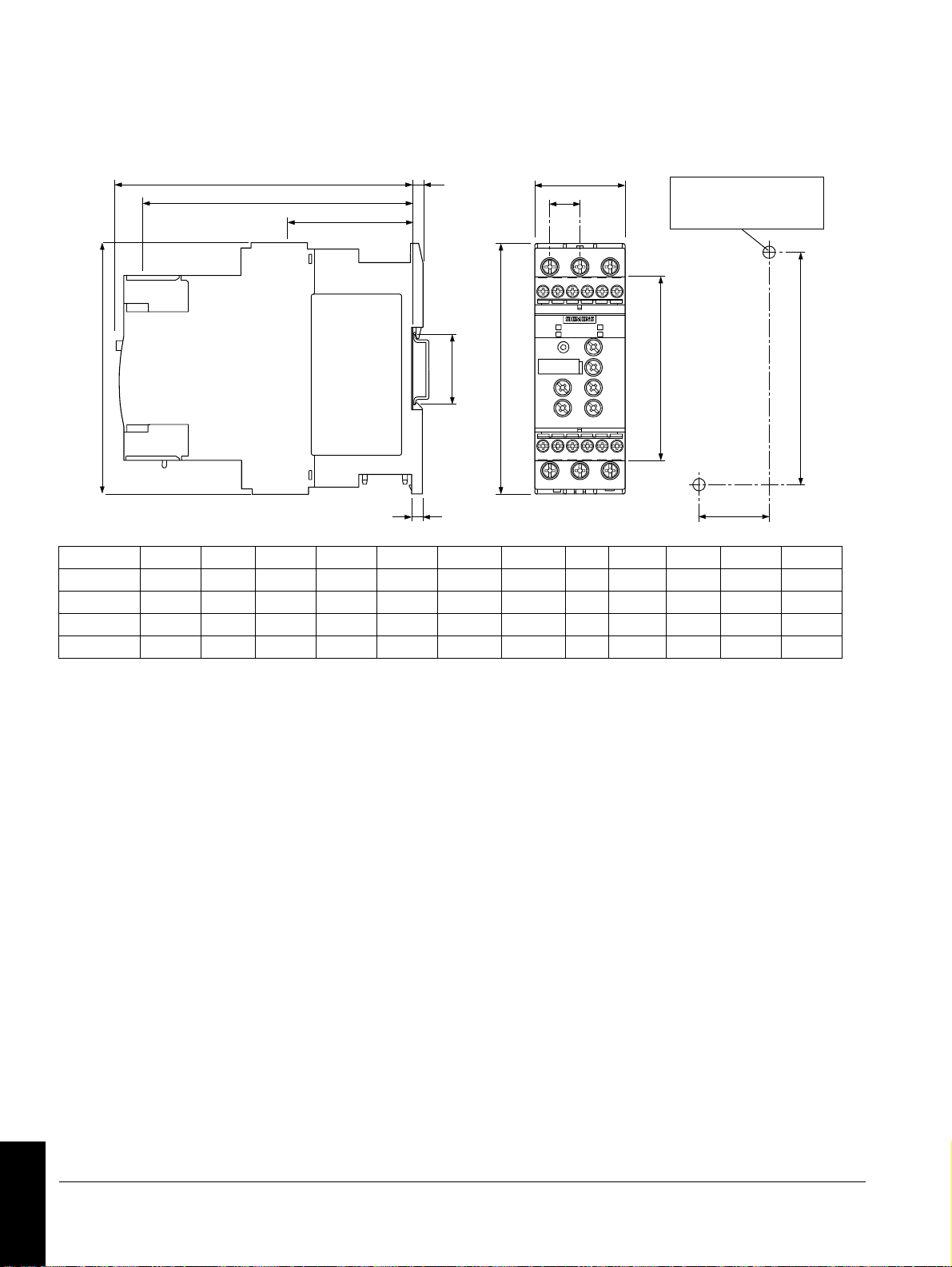
7.
d
b
a
c
g
e
h
f
k
l
i
35
3RW402: 1Nm / 9 lbf·in
3RW40 4: 2 Nm / 18 lbf·in
3RW403: 1Nm / 9 lbf·in
m
abc d e f ghikl m
3RW40 2.-1.... 125 (4.92) 45 (1.8) 92 (3.62) 149 (5.90) 126 (5.00) 14,4 (0.57) 63 (2.48) 5 (0.2) 6,5 (0.26) 35 (1.38) 115 (4.53) 125 (4.92)
3RW40 2.-2.... 125 (4.92) 45 (1.8) 92 (3.62) 149 (5.90) 144 (5.67 14,4 (0.57) 90,5 (3.56) 5 (0.2) 6,5 (0.26) 35 (1.38) 115 (4.53) 150 (5.90)
3RW40 3 160 (6.3) 55 (2.18) 110 (4.33) 165 (6.49) 140 (5.51) 18 (0.71) 63 (2.48) 5 (0.2) 6,5 (0.26) 30 (1.18) 150 (5.91) 144 (5.67)
3RW40 4 170 (6.7) 70 (2.76) 110 (4.33) 183 (7.20) 158 (6.22) 22,5 (0.89) 85 (3.35) 5 (0.2) 10 (0.4) 60 (2.36) 160 (6.3) 160 (6.3)
mm (inch)
Graphics
Technische Änderungen vorbehalten. Zum späteren Gebrauch aufbewahren.
Subject to change without prior notice. Store for use at a later date.
© Siemens AG 2006
Bestell-Nr. / Order No.: 3ZX1012-0RW40-2DA1
Printed in the Federal Republic of Germany
 Loading...