


8023832//2019-04-15
SICK AG
Erwin-Sick-Straße 1
D-79183 Waldkirch
www.sick.com
RFU610
Q U I C K S T A R T |
e n |
|
|
1About this document
The purpose of this Quickstart is to allow you to commission the RFU610-106xx RFID read/write device (UHF) quickly and easily and to achieve initial read results with transponders.
The Quickstart is valid for the regional variants listed in the “Device overview” sec tion: see Device overview, page 6.
The Quickstart describes the commissioning process for an application with an RFU610-106xx in an ambient temperature range of 0 °C to +50 °C.
Device variant RFU610-10600 (Ethernet variant, regional assignment: Europe) is used as the basis for the examples given, based on its default. The optional
GL6 photoelectric sensor (1059241) is used as an example for the industrialstandard read-cycle triggering of the RFU610-106xx. The photoelectric sensor can be connected with the RFU610-106xx as a trigger sensor. Additional trigger sen sors can be found at www.sick.com.
All rights reserved. Subject to change without notice.
2Safety information
•This chapter is dedicated to the safety of commissioning personnel and the operator of the system in which the device is integrated.
•Read this Quickstart carefully before commissioning the device in order to familiarize yourself with the device and its functions. The Quickstart is con sidered a part of the device and must be kept in an accessible location in the immediate vicinity of the device at all times!
•For country-specific particulars to consider when operating the device, see Operational restrictions, page 6.
 WARNING
Health hazard as a result of high-frequency electromagnetic radiation!
The RFU610-10600 (region: Europe) is designed for operation in accordance with ETSI EN 302208. During operation, the human exposure regulations cov ered by EN 50364 must be observed.
•Limit human exposure to electromagnetic fields. Suitable safety dis tances must be maintained during both short-term and long-term work in the radiation range of the integrated antenna. Minimum distances to be maintained between the antenna and the human body during longterm transmission: 10 cm and maximum radiation power of the antenna of 100 mW (20 dBm) as per ETSI.
The RFU610-10601 (region: USA/Canada/Mexico) satisfies the limit values of the FCC for exposure to radiation in an uncontrolled environment.
•During operation, a safety distance of at least 20 cm must be main tained between the antenna and the human body.
•To comply with the IP67 enclosure rating in operation, the following require ments must be met. If these requirements are not met, the device does not fulfill any specified IP enclosure rating.
°The side cover of the USB female connector and the microSD memory card slot must be screwed tight to the device.
°The SICK cables plugged into the M12 and M8 connections must be screwed tight.
°Any electrical connections that are not being used must be fitted with protective caps or plugs that are screwed tight (as in the delivery condi tion).
°Only operate the device without a cover for a short period while insert ing or removing the memory card or temporarily using the USB inter face. During this time, protect the device against moisture and dust.
•The type label on the lower side of the device contains a pressure equalizing membrane. If damaged, water and dust leaks could occur.
•Opening the screws of the device housing will invalidate any warranty claims against SICK AG. For further warranty provisions, see the General Terms and Conditions of SICK AG, e.g., on the delivery note of the device.
NOTE
SICK uses standard IP technology in its products. The emphasis is placed on availability of products and services.
SICK always assumes the following prerequisites:
•The customer ensures the integrity and confidentiality of the data and rights affected by its own use of the aforementioned products.
•In all cases, the customer implements the appropriate security measures, such as network separation, firewalls, virus protection, and patch management.
2.1Intended use
The RFU610-106xx is an intelligent UHF read/write device from the RFU61x prod uct family. The device is used for the automated, fixed identification of passive,
wireless-based data cards (transponders) on moving or stationary objects and their management.
As a compact read/write device, the RFU610-106xx has an internal antenna that is integrated into the housing. The device processes all standard passive transponders in accordance with ISO/IEC 18000-63 and EPCglobal UHF C1G2 in the regional UHF carrier frequency range. Thanks to its intelligent process logic, the device can be used either as a stand-alone solution or as part of a group in a network. The device sends the read results to a higher-level computer for further processing via its host interface. The device also receives commands for data card management (write, read, etc.) via this interface.
3Device description
3.1 Device view
78.8 (3.10) |
|
1 2 3 |
) |
|
1 |
3 |
2 |
|
(9.50.37) |
11.5(0.45 |
|
|
|
|
|
91° |
|
|
|
|
|
|
|
|
|
|
|
|
|
|
|
) |
|
|
|
|
4 |
5 |
6 |
|
17.5 |
|
0.12( |
|
|
|
|
||||
|
|
|
|
|
|
|
|
|
|
||
|
(0.69) |
|
3 |
|
|
|
|
|
|
|
|
|
|
|
17.5 |
|
|
|
|
|
|
|
|
|
|
|
|
|
|
|
|
|
|
|
|
|
|
|
(0.69) |
9 |
|
|
|
ß |
71 (2.80) |
|
|
|
|
|
|
|
|
|
|
||||
|
|
|
|
|
|
|
|
|
|
||
|
|
80 (3.15) |
|
|
|
38 (1.50) |
|
40 (1.57) |
|
||
8 |
|
|
|
|
|
|
|
|
|
|
|
|
|
|
|
|
|
|
|
|
|
|
) |
7 |
Ready |
|
Link/Act microSD |
|
|
|
|
|
|
|
5 (0.20 |
|
RF |
|
3.62) |
|
|
|
|
|
|||
|
|
|
|
(1.57) |
92 ( |
|
|
|
|
|
6.4 |
|
|
|
|
40 |
|
|
|
|
|
|
(0.25) |
|
94 (3.70) |
|
|
|
) |
|
|
|
|
||
|
106.4 (4.19) |
|
|
12 |
0.47 |
|
á à |
|
|||
|
|
|
|
|
|
|
( |
|
|
||
|
36 (1.42) |
â |
|
|
|
|
|
|
|
||
|
|
|
|
16 |
0.63) |
|
|
|
|
|
|
|
|
|
|
|
( |
|
|
|
|
|
|
Figure 1: Dimensional drawing of the RFU610-106xx (all variants), unit: mm (inch), decimal separator: period
1Port 1: Power (male connector, M12, 4-pin, A-coded)
2Port 3: Trigger (female connector, M8, 4-pin, A-coded)
3Port 2: PoE (female connector, M12, 8-pin, X-coded)
4Slot for microSD memory card
5“USB” connection (female connector, 5-pin, type Micro-B) interface for temporary use (service)
6Side type label
7Cover with integrated antenna
84 x multi-colored LED (status)
94 x RGB LED (process feedback)
ß2 x M5 blind tapped holes, 6 mm deep for attaching the mounting straps
à2 x M5 blind tapped holes, 7 mm deep for mounting the device
áType label with integrated pressure compensation membrane
â2 x screw (M2,5 socket screw), captive, for side cover
3.2 Status displays
|
|
|
|
|
|
|
|
|
|
|
|
|
|
Ready |
|
RF |
|
|
Link/Act |
|
microSD |
|
|
||||
|
|
|
|
|
|
||||||||
Status displays |
|
|
|
|
|
|
|
||||||
|
|
|
|
|
|
||||||||
Advertisement |
|
LED |
|
Color |
Status |
||||||||
Ready |
|
|
|
|
Lights up |
|
Green |
Device ready |
|||||
|
|
|
|
|
|
|
|
|
|
|
|||
|
|
|
|
|
|
|
Lights up |
|
Red |
Hardware error |
|||
|
|
|
|
|
|
|
|
|
|
|
|||
|
|
|
|
|
|
|
Flashing |
|
Green |
Flashing cyclically 4 x red, 1 x green in PROFINET |
|||
|
|
|
|
|
|
|
|
|
|
|
|
|
operation (single port): Trying to establish a con |
|
|
|
|
|
|
|
Flashing |
|
Red |
||||
|
|
|
|
|
|
|
|
nection to a PLC (IO controller) or loss of connec |
|||||
|
|
|
|
|
|
|
|
|
|
|
|
|
tion during operation |
RF |
|
|
|
|
Lights up |
|
Green |
UHF field activated |
|||||
|
|
|
|
|
|
|
|
|
|
|
|||
|
|
|
|
|
|
|
Lights up |
|
Red |
Internal antenna fault / HF part |
|||
|
|
|
|
|
|
||||||||
Link/Act |
|
Lights up |
|
Green |
Data traffic via Ethernet |
||||||||
|
|
|
|
|
|
||||||||
microSD |
|
Lights up |
|
Green |
MicroSD memory card inserted and ready for |
||||||||
|
|
|
|
|
|
|
|
|
|
|
|
|
operation. In this state, the device can either |
|
|
|
|
|
|
|
|
|
|
|
|
|
read data from the card or write data to the card. |
|
|
|
|
|
|
|
|
|
|
|
|
|
If the LED lights up, however, this does not indi |
|
|
|
|
|
|
|
|
|
|
|
|
|
cate that the device is accessing the card! |
|
|
|
|
|
|
|
Lights up |
|
Red |
MicroSD memory card inserted; however, it can |
|||
|
|
|
|
|
|
|
|
|
|
|
|
|
not be read or is defective |
8023832//2019-04-15/en |
RFU610 | SICK |
1 |
Advertisement |
LED |
Color |
Status |
|
Lights up |
Yellow |
Over SOPAS ET A function is started manually, |
|
|
|
which requires a memory card; however, the |
|
|
|
microSD memory card is not ready for operation |
|
|
|
(e.g., not plugged in, contacts contaminated, or |
|
|
|
without free storage space for writing). |
3.3 microSD memory card (optional accessory)
The device can execute the following functions on the plug-in memory card:
•Automated, additional storage of the internal parameter set to an external storage medium (cloning function), if available. This is done in the framework of the recommended safety concept for the device parameter sets. The func tion is triggered by saving the internal parameter set with the “permanent” option. The function is used,among other things, to conveniently transfer the parameter set to an replacement device of the same type in the event of an fault.
•Continuous recording of diagnostic read data after the first manual start, e.g., via SOPAS ET. Recording is resumed after a device restart when the function is set permanently.
The first time a parameter set is stored, we recommend that an empty memory card is used (if necessary, check and delete the contents of the card on the PC using a card reader).
The memory card is not included with delivery.
Only use types approved by SICK to ensure reliable function of the memory card, see www.sick.com/RFU61x. The memory card has no write protection that can be activated.
Inserting the memory card
The card slot can be accessed on the device behind the plastic foil, see Device description, page 1.
Maintaining enclosure rating IP67: see Safety information, page 1.
1.Switch off the supply voltage to the device.
2.Loosen both screws on the cover.
3.Carefully fold up the cover.
4.Making sure it is in the correct position (with the contacts pointing to the front and down – see the symbol on the device), insert the memory card into the card slot until it locks into place.
5.Screw the cover back on.
6.Switch the supply voltage for the device back on.
7.Once it is switched on, the device automatically detects the presence of a memory card and, depending on the card’s content, behaves as follows:
°If the card is empty or if it contains a parameter set that cannot be interpreted by the device, the device saves its currently valid internal parameter set to the card (provided there is sufficient storage space) and starts with the internal parameter set.
°If the card contains a parameter set that can be interpreted by the device, the device overwrites the currently valid internal parameter set with this external parameter set.
The goal is for the internal parameter set and the parameter set saved externally to always be identical.
NOTE
Possible data loss or irreparable damage to the memory card!
The device does not signal access to the card.
•Only use memory card when the device power is off.
•Do not remove the memory card or switch off the supply voltage while the SOPAS ET configuration software is making changes to the parame ter values with the “permanent” option or starting functions in the device that access the memory card (e.g., logging data).
•To remove the memory card safely during operation, select the Remove card function under Analysis Tools/MicroSD memory card and wait for SOPAS ETto provide confirmation.
4Mounting
4.1 Scope of delivery
•Device in the version ordered. Electrical connections fitted with protective caps or plugs. Without connecting cables. Without brackets.
•Regional printed Quickstarts: see Device overview, page 6. Other lan guage versions may be available in PDF format on the RFU610-106xx prod uct page online at: www.sick.com/RFU61x.
4.2 Auxiliary equipment required
•2 x M5 screws for mounting the device on a mounting device (bracket) sup plied by the customer. Screw length is dependent on the mounting base (wall thickness of the bracket).
•When using an optional SICK bracket, the screws for mounting the device on the bracket are included in the scope of delivery of the bracket.
4.3 Installation requirements
•The permissible ambient conditions for operating the device must be observed, e.g., assigned region, ambient temperature, ground potential: see Technical data (excerpt), page 5 and see Electrical installation,
page 2.
•The device must be mounted using the 2 M5 blind tapped holes provided, see Device description, page 1.
•Stable mounting equipment with sufficient load-bearing capacity and appro priate dimensions for the device. Weight approx. 313 g (without cables), see Device description, page 1.
•No electrically conductive material between transponder and device.
4.4 Mounting the device
1.Select a suitable mounting location for the device. The mounting location and position depend on the antenna field of the device and the transpon ders used.
2.Perform one of the following steps:
°Mount the device on the bracket provided by the customer using the
2 screws. Screw the M5 screws no more than 7 mm deep into the blind tapped holes, see Device description, page 1.
°Mount the device on the SICK mounting accessories ordered sepa rately.
3.Align the surface of the internal antenna of the device (front face) to the data card on the object. While doing so, take into account the shape, align ment, and dimensions of the antenna fields. Avoid as far as possible any large metal surfaces positioned to the front. If this is not possible, do not mount the antenna plane parallel with the surface.
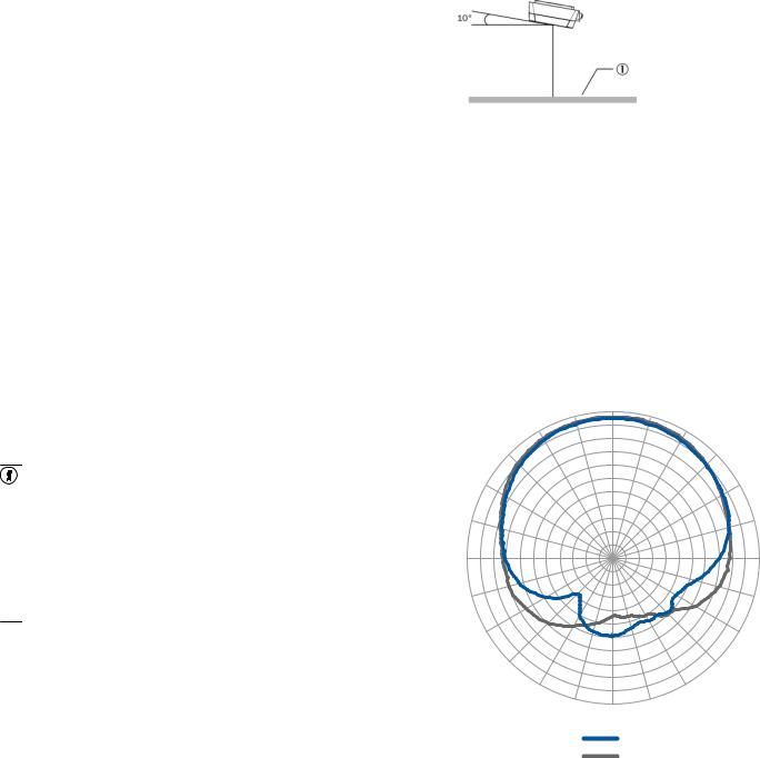
Figure 2: Selection of the approach angle with a large metal surface on the front. e.g., 10°
1 Metal surface
4.Ensure there is no electrically conductive material (e.g., metal or liquids) or persons between the device and the transponder during the write or read process. This will absorb or reflect the generated UHF field and thereby reduce the sensing range.
Sensing range of the reading and writing field
The UHF field of the internal antenna is influenced by its environment, making it impossible to provide a “clear” demarcation of the sensing range. Application-spe cific reflections can result in both overreaches and “holes”. In addition to the read results, the RFU device can also output diagnostic data that provide an indication of the write and read quality. This data can be used to achieve optimum read results when setting up the system.
The quality of the transponder and the material of the object also determine the sensing range. The quality of the transponder is determined by the antenna gain, the integrated transponder chip and the related sensitivity, and the reflected energy.
The radiation pattern shown here for the internal antenna of the device was obtained in a reproducible environment (absorber chamber) for illustrative pur poses. It may therefore only have limited applicability to your specific application.
|
–15° |
0° |
15° |
|
0 |
||
|
|
|
|
–30° |
|
–3 |
30° |
|
|
|
|
–45° |
|
–6 |
45° |
|
–9 |
||
|
|
|
|
|
|
–12 |
|
–60° |
|
–15 |
60° |
|
|
||
|
|
–18 |
|
|
|
–21 |
|
–75° |
|
–24 |
75° |
|
|
–27 |
|
|
|
–30 |
|
–90° |
|
–33 |
90° |
–105° |
|
|
105° |
–120° |
|
|
120° |
–135° |
|
|
135° |
–150° |
|
|
150° |
|
–165° |
180° |
165° |
|
|
|
|
|
|
1 |
|
|
|
2 |
|
Figure 3: Measured antenna gain in dBic at 866.5 MHz, LHCP (left-hand circularly polarized)
1Azimuth plane (horizontal)
2Elevation plane (vertical)
5Electrical installation
•The electrical installation must only be performed by electrically qualified persons.
•Standard safety requirements must be observed when working on electrical systems!
•Only connect and disconnect electrical connections for the device when the power is off. Otherwise, there is a risk of damaging the devices.
•When using connecting or extension cables with an open end, make sure that bare wire ends are not touching (risk of short-circuit when the supply voltage is switched on). Wires must be appropriately insulated from each other.
•Wire cross-sections in the supply cable from the user’s power system must be designed in accordance with the applicable national standards.
8023832//2019-04-15/en |
RFU610 | SICK |
2 |
 Loading...