


 Loading...
O P E R A T I N G I N S T R U C T I O N S
V4000 Press Brake sensor system
for protecting the press brake
GB

Operating instructions
V4000 PB
This document is protected by copyright. The SICK AG company retains this right. Reproducing this document in whole or part is only permissible within the limits of the statutory regulations of copyright law. Modifying or abridging the document is impermissible without the express written permission of from the SICK AG company.
2 |
© SICK AG • Industrial Safety Systems • Germany • All rights reserved |
8010505/TL63/2009-11-27 |

Insert
V4000 PB
Update
a
WARNING
Update
Please take note of the following updates to this document!
Based on Machinery Directive 2006/42/EC, we have added the following supplementary data or change notices on our product to the following document.
Scope
This document is an original document.
Cited standards and directives
The standards and directives cited in these operating instructions might have changed. The following list indicates the standards and directives that might have been cited and their successive versions.
Kindly replace the standards and directives cited in these operating instructions with the successive versions listed in the table.
Previous standard or directive |
Successive standard and directive |
Machinery Directive 98/37/EC |
Machinery Directive 2006/42/EC |
Directive 93/68/EEC |
Directive 93/68/EC |
EMC directive 89/336/EEC |
EMC directive 2004/108/EC |
Low Voltage Directive 73/23/EC |
Low Voltage Directive 2006/95/EC |
DIN 40 050 |
EN 60 529 |
IEC 536:1976 |
EN 61 140 |
DIN EN 50 178:1998-04/ |
EN 50 178 |
VDE 0160:1998-04 |
|
EN 775 |
EN ISO 10 218-1 |
EN 292-1 |
EN ISO 12 100-1 |
EN 292-2 |
EN ISO 12 100-2 |
EN 954-1 |
EN ISO 13 849-1 |
EN 418 |
EN ISO 13 850 |
EN 999 |
EN 999+A11) |
EN 294 |
EN ISO 13 857 |
EN 811 |
EN ISO 13 857 |
EN 1050 |
EN ISO 14 121-1 |
IEC 68, part 2-27 or IEC 68 |
EN 60 068-2-27 |
IEC 68, part 2-29 |
EN 60 068-2-27 |
IEC 68, part 2-6 |
EN 60 068-2-6 |
prEN 50 1001 |
EN 61 496-1 |
ANSI B11.19-1990 |
ANSI B11.19:200304, Annex D |
|
|
1) EN 999 will be replaced by EN ISO 13 855.
8010505/TL63/2009-11-27 |
© SICK AG • Industrial Safety Systems • Germany • All rights reserved |
Update
Insert
V4000 PB
Electrical installation
aPrevent the formation of a potential difference between the load and the protective device!
WARNING |
If you connect loads that are not reverse-polarity protected to the OSSDs or the safety |
|
|
outputs, you must connect the 0 V connections of these loads and those of the |
|
|
corresponding protective device individually and directly to the same 0 V terminal strip. |
|
|
This is the only way to ensure that, in the event of a defect, there can be no potential |
|
|
difference between the 0 V connections of the loads and those of the corresponding |
|
|
protective device. |
|
|
OSSD1 Safety output 1 OSSD2 Safety output 2 |
OSSD1 Safety output 1 OSSD2 Safety output 2 |
Technical specifications
Safety-related parameters according to EN ISO 13 849, EN 62 061, IEC 61 508:
Type
Safety Integrity Level2)
Category
Performance Level2)
PFHd (mean probability of a dangerous failure per hour)
TM (mission time)
Type 4 (IEC 61 496)
SIL3 (IEC 61 508),
SILCL3 (EN 62 061)
Category 4 (EN ISO 13 849) Category 4 (EN 9543))
PL e (EN ISO 13 849) 1.52 × 10⁻⁸
16.6 years (EN ISO 13 849)
EC declaration of conformity
Note You can obtain the EC declaration of conformity with the standards used at: www.sick.com
2)For detailed information on the exact design of your machine/system, please contact your local SICK representative.
3)Only valid for the assumption of conformity until 28.12.2009. From then on it will only be permissible to use the successor EN ISO 13 849.
© SICK AG • Industrial Safety Systems • Germany • All rights reserved |
8010505/TL63/2009-11-27 |

Insert
V4000 PB
Update
Checklist for the manufacturer
L
Checklist for the manufacturer/installer for the installation of electrosensitive protective equipment (ESPE)
Details about the points listed below must be present at least during initial commissioning — they are, however, dependent on the respective application, the specifications of which are to be controlled by the manufacturer/installer.
This checklist should be retained and kept with the machine documentation to serve as reference during recurring tests.
1. |
|
Have the safety rules and regulations been observed in compliance with the directives/standards applicable to |
|
|
Yes |
|
No |
|
|
|
the machine? |
|
|
|
|
|
|
|
|
|
|
|
|
|
|
|
2. |
|
Are the applied directives and standards listed in the declaration of conformity? |
|
|
Yes |
|
No |
|
3. |
|
Does the protective device fulfil the required PL/SILCL and PFHd according to EN ISO 13 8491/EN 62 061 and |
|
|
Yes |
|
No |
|
|
|
the type according to EN 61 4961? |
|
|
|
|
|
|
4. |
|
Is the access to the hazardous area/hazardous point only possible through the protective field of the ESPE? |
|
|
Yes |
|
No |
|
5. |
Have appropriate measures been taken to prevent (mechanical protection) or monitor unprotected presence in |
|
|
Yes |
|
No |
|
|
|
|
the hazardous area when protecting a hazardous area/hazardous point and have these been secured against |
|
|
|
|
|
|
|
|
removal? |
|
|
|
|
|
|
6. |
|
Are additional mechanical protective measures fitted and secured against manipulation which prevent reaching |
|
|
Yes |
|
No |
|
|
|
under, over or around the ESPE? |
|
|
|
|
|
|
7. |
|
Has the maximum stopping and/or stopping/run-down time of the machine been measured, specified and |
|
|
Yes |
|
No |
|
|
|
documented (at the machine and/or in the machine documentation)? |
|
|
|
|
|
|
8. |
|
Has the ESPE been mounted such that the required safety distance from the nearest hazardous point has been |
|
|
Yes |
|
No |
|
|
|
achieved? |
|
|
|
|
|
|
9. |
|
Are the ESPE devices correctly mounted and secured against manipulation after adjustment? |
|
|
Yes |
|
No |
|
10. |
Are the required protective measures against electric shock in effect (protection class)? |
|
|
Yes |
|
No |
|
|
11. |
Is the control switch for resetting the protective device (ESPE) or restarting the machine present and correctly |
|
|
Yes |
|
No |
|
|
|
|
installed? |
|
|
|
|
|
|
12. |
Are the outputs of the ESPE (OSSDs, ASInterface Safety at Work) integrated in compliance with the required |
|
|
Yes |
|
No |
|
|
|
|
PL/SILCL according to EN ISO 13 849/EN 62 061 and does the integration comply with the circuit diagrams? |
|
|
|
|
|
|
13. |
Has the protective function been checked in compliance with the test notes of this documentation? |
|
|
Yes |
|
No |
|
|
14. |
Are the given protective functions effective at every setting of the operating mode selector switch? |
|
|
Yes |
|
No |
|
|
15. |
Are the switching elements activated by the ESPE, e.g. contactors, valves, monitored? |
|
|
Yes |
|
No |
|
|
16. |
Is the ESPE effective over the entire period of the dangerous state? |
|
|
Yes |
|
No |
|
|
17. |
Once initiated, will a dangerous state be stopped when switching the ESPE on or off and when changing the |
|
|
Yes |
|
No |
|
|
|
|
operating mode, or when switching to another protective device? |
|
|
|
|
|
|
18. |
Has an information label for the daily check been attached so that it is easily visible for the operator? |
|
|
Yes |
|
No |
|
|
19. |
Have you made sure that the protective device itself when mounted is not a source of danger during machine |
|
|
Yes |
|
No |
|
|
|
|
operation (for example, catching between the device and parts of the machine)? |
|
|
|
|
|
|
|
|
|
|
|
|
|
|
|
This checklist does not replace the initial commissioning, nor the regular inspection by qualified safety personnel.
8010505/TL63/2009-11-27 |
© SICK AG • Industrial Safety Systems • Germany • All rights reserved |

Update
Insert
V4000 PB
© SICK AG • Industrial Safety Systems • Germany • All rights reserved |
8010505/TL63/2009-11-27 |

Operating instructions |
Contents |
|
|
|
||
V4000 PB |
|
|
|
|
|
|
Contents |
|
|
|
|||
|
|
|
|
|||
|
1 |
About this document ...................................................................................................... |
6 |
|||
|
|
1.1 |
Function of this document.................................................................................... |
6 |
||
|
|
1.2 |
Target groups ........................................................................................................ |
6 |
||
|
|
1.3 |
Scope ..................................................................................................................... |
|
|
6 |
|
|
1.4 |
Depth of information............................................................................................. |
6 |
||
|
|
1.5 |
Abbreviations......................................................................................................... |
7 |
||
|
|
1.6 |
Symbols used ........................................................................................................ |
8 |
||
|
2 |
On safety.......................................................................................................................... |
|
|
9 |
|
|
|
2.1 |
Specialist personnel.............................................................................................. |
9 |
||
|
|
2.2 |
Applications of the system ................................................................................... |
9 |
||
|
|
2.3 |
Correct use of the system.................................................................................. |
10 |
||
|
|
2.4 |
General protective notes and protective measures......................................... |
10 |
||
|
|
2.5 |
Safety in operation............................................................................................. |
11 |
||
|
|
2.6 |
Environmental protection .................................................................................. |
16 |
||
|
|
|
2.6.1 |
Disposal ............................................................................................ |
16 |
|
|
3 |
Product description ..................................................................................................... |
17 |
|||
|
|
3.1 |
Special features ................................................................................................. |
17 |
||
|
|
3.2 |
Safety concept.................................................................................................... |
18 |
||
|
|
|
3.2.1 |
Protection principle of the V4000 PB ............................................. |
18 |
|
|
|
|
3.2.2 |
Protective volume during the operating cycle ................................ |
20 |
|
|
|
|
3.2.3 |
Intrusion of the protective volume during the operating cycle...... |
21 |
|
|
|
3.3 |
Range of use ...................................................................................................... |
22 |
||
|
|
3.4 |
Structure of the device ...................................................................................... |
23 |
||
|
|
|
3.4.1 |
Sender and receiver......................................................................... |
23 |
|
|
|
|
3.4.2 |
Displays at the sender and receiver ............................................... |
24 |
|
|
|
|
3.4.3 |
Interfaces at the receiver................................................................. |
26 |
|
|
|
|
3.4.4 |
PBI (press brake interface).............................................................. |
28 |
|
|
|
|
3.4.5 |
CDS (Configuration & Diagnostics Software).................................. |
29 |
|
|
|
|
3.4.6 |
External operating elements ........................................................... |
31 |
|
|
|
3.5 |
Possible system configurations......................................................................... |
31 |
||
|
|
|
3.5.1 |
Source of the operator signals ........................................................ |
33 |
|
|
|
|
3.5.2 |
Baud rate communication interface ............................................... |
33 |
|
|
|
|
3.5.3 |
Application name ............................................................................. |
33 |
|
|
|
|
3.5.4 |
Repetition interval of power-up cycle.............................................. |
33 |
|
|
|
|
3.5.5 |
Mounting of receiver ........................................................................ |
34 |
|
|
|
|
3.5.6 |
Speed-dependent muting ................................................................ |
34 |
|
|
|
|
3.5.7 |
Position-sensing system .................................................................. |
34 |
|
|
|
|
3.5.8 |
External device monitoring (EDM)................................................... |
35 |
|
|
|
|
3.5.9 |
Default value for braking distance.................................................. |
35 |
|
|
|
|
3.5.10 |
Travel for determining the braking distance .................................. |
36 |
|
|
|
|
3.5.11 |
Braking offset ................................................................................... |
36 |
|
|
|
|
3.5.12 |
Target speed vslow for determining the braking distance ............... |
36 |
|
3.5.13Monitoring of the slow closing speed vcrawl from the pinch
point.................................................................................................. |
37 |
3.5.14Maximum closing speed and maximum overall machine
|
overrun.............................................................................................. |
37 |
3.5.15 Travel for determining the overall machine overrun...................... |
38 |
|
3.5.16 |
Standstill time for determining the top dead centre...................... |
38 |
3.5.17 |
Start delay for closing movement .................................................. |
39 |
8010505/TL63/2009-11-27 |
© SICK AG • Industrial Safety Systems • Germany • All rights reserved |
3 |

Contents
Operating instructions
|
|
|
|
|
V4000 PB |
|
|
|
|
|
|
||
|
|
|
3.5.18 |
Time for standstill detection ............................................................ |
39 |
|
|
|
|
3.5.19 |
Settling times for inputs ................................................................... |
39 |
|
|
|
|
3.5.20 |
Discrepancy times for inputs ........................................................... |
40 |
|
|
|
|
3.5.21 |
Start signal at reduced protective volume ...................................... |
40 |
|
|
|
|
3.5.22 |
Minimum state time for standard outputs...................................... |
41 |
|
|
|
|
3.5.23 |
Minimum switch-off time for safety-relevant outputs..................... |
41 |
|
|
|
|
3.5.24 |
Bypass............................................................................................... |
41 |
|
|
|
3.6 |
Protective operation ........................................................................................... |
42 |
||
|
|
|
3.6.1 |
Power-up cycle .................................................................................. |
42 |
|
|
|
|
3.6.2 |
Teach-in............................................................................................. |
43 |
|
|
|
|
3.6.3 |
Protective volume modes in protective operation .......................... |
43 |
|
|
|
3.7 |
System sequences in protective operation....................................................... |
46 |
||
|
|
|
3.7.1 |
Power-up cycle in standard mode.................................................... |
47 |
|
|
|
|
3.7.2 |
Teach-in............................................................................................. |
51 |
|
|
|
|
3.7.3 |
Operating cycle in standard mode................................................... |
53 |
|
|
|
|
3.7.4 |
Operating cycle in box mode............................................................ |
55 |
|
|
|
|
3.7.5 |
Operating cycle in back-stop mode ................................................. |
57 |
|
|
|
3.8 |
Alignment mode.................................................................................................. |
59 |
||
|
4 |
Mounting....................................................................................................................... |
|
|
60 |
|
|
|
4.1 |
Steps for mounting ............................................................................................. |
60 |
||
|
|
|
4.1.1 |
Mounting the sender or receiver using SICK mounting kit 1 ......... |
60 |
|
|
|
|
4.1.2 |
Mounting the sender or receiver using SICK mounting kit 2 ......... |
61 |
|
|
|
|
4.1.3 |
Sticker: Information for daily inspection ......................................... |
62 |
|
|
5 |
Electrical installation................................................................................................... |
63 |
|||
|
|
5.1 |
Connecting the receiver .................................................................................... |
63 |
||
|
|
5.2 |
Connecting the sender ....................................................................................... |
66 |
||
|
|
5.3 |
Making up the connections for receiver and sender....................................... |
67 |
||
|
|
5.4 |
Connecting the PBI ............................................................................................ |
67 |
||
|
|
5.5 |
External device monitoring (EDM) ..................................................................... |
69 |
||
|
|
5.6 |
Bypass................................................................................................................. |
|
|
70 |
|
|
5.7 |
Configuration connection (serial interface)....................................................... |
71 |
||
|
6 |
Configuration................................................................................................................ |
|
|
72 |
|
|
|
6.1 |
Delivery state ...................................................................................................... |
72 |
||
|
|
6.2 |
Configuration preparations ................................................................................ |
73 |
||
|
7 |
Commissioning............................................................................................................. |
|
|
74 |
|
|
|
7.1 |
Test notes |
........................................................................................................... |
|
74 |
|
|
7.2 |
Aligning sender and receiver ............................................................................. |
74 |
||
|
|
|
7.2.1 |
Initial alignment ................................................................................ |
74 |
|
|
|
|
7.2.2 |
Alignment following a tooling change.............................................. |
81 |
|
|
|
7.3 |
Function check ................................................................................................... |
83 |
||
|
|
7.4 |
Regular checks of the protective device by specialist personnel................... |
86 |
||
7.5Daily checks of the protective device by authorised commissioned
|
persons ............................................................................................................... |
86 |
8 Operation ...................................................................................................................... |
88 |
|
8.1 |
Switching the machine on.................................................................................. |
88 |
8.2 |
Selecting protective volume mode .................................................................... |
89 |
8.3 |
Resetting ............................................................................................................. |
89 |
8.4 |
Carrying out a power-up cycle............................................................................ |
89 |
8.5 |
Carrying out teach-in .......................................................................................... |
91 |
8.6 |
Bending in standard mode................................................................................. |
92 |
4 |
© SICK AG • Industrial Safety Systems • Germany • All rights reserved |
8010505/TL63/2009-11-27 |

Operating instructions |
Contents |
|
|
|
||
V4000 PB |
|
|
|
|
|
|
|
8.7 |
Bending in box mode |
92 |
|||
|
|
|||||
|
|
8.8 |
Bending in back-stop mode.............................................................................. |
92 |
||
|
|
8.9 |
Changing the sheet thickness ........................................................................... |
92 |
||
|
|
8.10 |
Tool changing ..................................................................................................... |
93 |
||
|
|
8.11 |
Care and maintenance ...................................................................................... |
93 |
||
|
9 |
Diagnostics................................................................................................................... |
|
|
94 |
|
|
|
9.1 |
Response to errors and malfunctions............................................................... |
94 |
||
|
|
9.2 |
Error displays of the LEDs.................................................................................. |
94 |
||
|
|
9.3 |
Error displays of the 7-segment display............................................................ |
95 |
||
|
|
9.4 |
Extended diagnostics via CDS........................................................................... |
97 |
||
|
|
9.5 |
SICK support....................................................................................................... |
98 |
||
|
10 |
Technical data.............................................................................................................. |
|
|
99 |
|
|
|
10.1 |
Device data sheet .............................................................................................. |
99 |
||
|
|
|
10.1.1 V4000 PB technical data................................................................. |
99 |
||
|
|
|
10.1.2 Technical data for PBI (press brake interface)............................. |
105 |
||
|
|
|
10.1.3 Incremental encoder technical data ............................................. |
106 |
||
|
|
10.2 |
Dimensional drawings ..................................................................................... |
107 |
||
|
|
|
10.2.1 |
Sender and receiver....................................................................... |
107 |
|
|
|
|
10.2.2 SICK mounting kit 1 ....................................................................... |
108 |
||
|
11 |
Ordering information ................................................................................................. |
109 |
|||
|
|
11.1 |
Scope of delivery.............................................................................................. |
109 |
||
|
|
11.2 |
Available systems............................................................................................. |
109 |
||
|
|
11.3 |
Accessories....................................................................................................... |
109 |
||
|
12 |
Glossary ...................................................................................................................... |
|
|
111 |
|
|
13 |
Annex |
....................................................................................................................... |
|
|
114 |
|
|
13.1 |
Detailed system sequences in protective operation...................................... |
114 |
||
|
|
|
13.1.1 |
Power-up cycle................................................................................ |
114 |
|
|
|
|
13.1.2 |
Teach-in .......................................................................................... |
116 |
|
|
|
|
13.1.3 |
Standard mode .............................................................................. |
118 |
|
|
|
|
13.1.4 Box or back-stop mode with interruption of the protective |
|
||
|
|
|
|
volume ............................................................................................ |
120 |
|
|
|
13.2 |
Declaration of Conformity................................................................................ |
122 |
||
|
|
13.3 |
Manufacturer’s checklist ................................................................................. |
124 |
||
|
|
13.4 |
List of tables..................................................................................................... |
125 |
||
|
|
13.5 |
List of illustrations............................................................................................ |
126 |
||
|
|
13.6 |
Index ................................................................................................................. |
|
|
128 |
8010505/TL63/2009-11-27 |
© SICK AG • Industrial Safety Systems • Germany • All rights reserved |
5 |

Chapter 1 |
About this document |
Operating instructions
V4000 PB
1 About this document
Read this chapter carefully before working with the operating instructions and the
V4000 Press Brake system.
For "V4000 Press Brake system" we shall use the abbreviation "V4000 PB" from now on.
1.1Function of this document
These operating instructions are intended for the technical personnel of the machine manufacturer or the machine operator in regards to safe mounting, electrical installation, configuration, commissioning, operation and diagnostics of the V4000 PB sensor.
These operating instructions do not provide instructions for operating machines on which the V4000 PB is, or will be, integrated. Information of this kind will be found in the operating instructions for the machine.
1.2Target groups
These operating instructions are intended for manufacturers, operators and the users of press brakes which are to be protected by a V4000 PB. It also addresses people who integrate the V4000 PB into a machine, initialise its use, or who check the unit.
1.3Scope
Note These operating instructions apply for the V4000 PB with the following type label entry in the Operating Instructions field: 8 010 501. This document is part of SICK part number 8 010 501 (V4000 Press Brake sensor system in all available languages).
You will require a CDS (Configuration & Diagnostic Software) version 3.0 or greater for the configuration and diagnostics of this system. To determine the software version, select the Module info item from the ? menu in the menu bar.
1.4Depth of information
These operating instructions contain information on the V4000 PB regarding the following subjects:
|
Mounting |
|
Error diagnostics and remedying |
|
Electrical installation |
|
Technical data and order numbers |
|
Configuration and commissioning |
|
Conformity and approval |
|
Operation, care and maintenance |
|
|
Planning and using protective devices such as the V4000 PB sensor also require specific technical skills which are not detailed in these operating instructions.
When operating the V4000 PB sensor, the national, local and statutory rules and regulations must be observed.
General information on health and safety using opto-electronic protective devices is contained in the brochure "Safe Machines with Opto-Electronic Protective Devices".
6 |
© SICK AG • Industrial Safety Systems • Germany • All rights reserved |
8010505/TL63/2009-11-27 |
Operating instructions |
About this document |
Chapter 1 |
V4000 PB
Note
We also refer you to the SICK homepage on the Internet at http://www.sick.com
Here you will find:
These operating instructions in different languages for viewing and printing
The EC Declaration of Conformity
1.5Abbreviations
ANSI American National Standards Institute
BWS Electro-sensitive protective equipment (ESPE) (e. g. V4000 PB)
CDS SICK Configuration & Diagnostic Software = software for configuring and diagnosing the V4000 PB system
EDM External device monitoring
ESPE Electro-sensitive protective equipment HMI Human machine interface
LD Laser diode
LELD Light-emitting diode MP Mute point
NC Numerical control
OMO Overall machine overrun ORT Overall response time
OSSD Output signal switching device = signal output of the protective device to the controller used for switching off the movement which is the source of danger
PBDC Programmed bottom dead centre PBI Press brake interface
PTDC Programmed top dead centre PP Pinch point
SP Switch-over point (from vp to vslow) SPLC Safety programmable logic control
V4000 PB V4000 Press Brake (sensor system)
8010505/TL63/2009-11-27 |
© SICK AG • Industrial Safety Systems • Germany • All rights reserved |
7 |

Chapter 1 |
About this document |
Operating instructions
Recommendation
Note
;, , ;O(
O Yellow, Ö Yellow,
o Yellow
,
> Action …
V4000 PB
1.6Symbols used
Recommendations are designed to provide some assistance for your decision-making process regarding application of a certain function or technical measure.
Notes provide special information about the device.
Display indicators show the status of the 7-segment display of the receiver: 7 Constant display of the letter F
Flashing display of the letter F 7O) Alternating display of F and 2
LED symbols describe the state of an LED:
O |
The LED is illuminated constantly. |
ÖThe LED is flashing.
o |
The LED is off. |
ON or OFF state: ON OFF
Instructions for taking action are shown by an arrow. Read carefully and follow the instructions for action.
aWarning!A warning indicates concrete or potential dangers. They save you from harm.
WARNING |
Read warnings carefully and abide by them! |
nSoftware notes show the location in the CDS (Configuration & Diagnostic Software) where you can make the appropriate settings and adjustments. Go to the View menu, Dialogue windows of the CDS and activate the item tabs to view the named dialogue boxes as required. Otherwise use the software wizard to make the desired settings.
s r |
Sender and receiver |
|
|
In drawings and diagrams, the s symbol denotes the sender and the symbol r the |
|
|
receiver. |
|
|
The term "dangerous state" |
|
|
In the drawings in these operating instructions, the dangerous state (standard term) of the |
|
|
machine is always represented as a movement of a machine part. In practical operation |
|
|
there may be a number of different dangerous states: |
|
|
|
Machine movements |
|
|
Electrical conductors |
|
|
Visible or invisible radiation |
|
|
A combination of several risks and hazards |
Representation of the signals for teach-in, alignment mode and selection of protective volume mode
These operating instructions also describe the V4000 PB input and output signals. As a way of uniquely representing the signals for teach-in, alignment mode and selection of protective volume mode (input signals), tactile switching amplifiers (buttons, switches) are used. The signals can be generated at the inputs of the V4000 PB by, for example, foot switches, alignment buttons, teach-in buttons, selector switches and key-operated switches or by the corresponding switching elements on the HMI of the press controller.
8 |
© SICK AG • Industrial Safety Systems • Germany • All rights reserved |
8010505/TL63/2009-11-27 |

Operating instructions |
On safety |
Chapter 2 |
V4000 PB |
|
|
|
|
2 On safety
This chapter deals with your own safety and the safety of the operators.
>Read this chapter carefully before working with the V4000 PB or with the machine protected by the V4000 PB.
2.1Specialist personnel
The V4000 PB must be mounted, connected, commissioned and serviced only by specialist personnel. Specialist personnel are defined as persons who
due to their technical training and experience possess sufficient knowledge in the field of safety equipment for making press brakes safe
and
who have been instructed by the responsible machine operator in the operation of the machine and the current valid safety guidelines
and
have sufficient familiarity with the relevant national industrial safety regulations, work safety regulations, directives and the generally recognised code of practice of the industry (for example, DIN standards, VDE specifications, technical codes of other EC member states) that they can judge whether the press brake is safe from the occupational safety point of view
and
have access to and have read these operating instructions.
As a rule these will be specialist personnel, the manufacturer of the ESPE or even such persons who have been given the corresponding training by the ESPE manufacturer, who are mainly concerned with inspecting and testing ESPEs and have been commissioned by the ESPE operator in this regard.
2.2Applications of the system
The V4000 PB is an ESPE (electro-sensitive protective equipment) device designed to protect the area beneath the die of press brakes at high closing speeds. As soon as an object enters the protective volume beneath the die, the ESPE issues the signal to the press controller to stop the fast closing movement and this system must then stop the closing movement.
The V4000 PB system consists of a sender and a receiver which are mounted on the press crosshead. The protective volume between the sender and the receiver moves with the press crosshead and thus ensures that the safeguarded area stays beneath the die.
The system is a Type 4 ESPE as defined by to IEC 61 496-1 and 2 and is therefore allowed for use with controls of safety category 4 in compliance with EN 954-1. It may be used in safety applications up to SIL 3 in accordance with IEC 61 508.
8010505/TL63/2009-11-27 |
© SICK AG • Industrial Safety Systems • Germany • All rights reserved |
9 |
Chapter 2 |
On safety |
Operating instructions
a
WARNING
a
WARNING
Fig. 1: Warning regarding laser class 1M
V4000 PB
Use of the V4000 PB in the open air or explosion hazard areas is not permitted. The V4000 PB can only be used in normal industrial environments.
Do not use the V4000 PB as a separating protective measure!
An opto-electronic protective device provides indirect protection, e.g., by switching off the power at the source of the hazard. It cannot provide protection neither from parts thrown out, nor from emitted radiation. Transparent objects are not detected.
Depending on its applications, mechanical protective devices may be needed in addition to the V4000 PB.
2.3Correct use of the system
The V4000 PB system is intended to be used solely at a fixed location on press brakes and may only be used as defined by Section 2.2 "Applications of the system". It must be used only by specialist personnel and only on the machine where it has been mounted and initially commissioned by specialist personnel in accordance with these operating instructions.
SICK AG accepts no claims for liability if the equipment is used in any other way or if modifications are made to the device, even in the context of mounting and installation.
2.4General protective notes and protective measures
Protective notes
Please observe the following protective notes in order to ensure the correct and safe use of the V4000 PB.
Warnings on the V4000 PB must be observed without fail.
The V4000 PB meets the requirements of laser protection class 1 M. Do not look into the laser beam neither with the naked eye nor using optical equipment (such as binoculars).
LASER RADIATION
DO NOT STARE INTO THE BEAM OR VIEW
DIRECTLY WITH OPTICAL INSTRUMENTS
CLASS 1M LASER PRODUCT
ACCORDING TO IEC 60825-1:2001
Max. output: < 5mW
Puls duration: < 2ms
Wavelength: 620 TO 650 nm
Complies with 21 CFR 1040.10 and 1040.11 except for deviations pursuant to laser notice No. 50, July 2001
This device meets the norms: CDRH 21 CFR 1040.10, 1040.11 as well as DIN EN 60 825:2001. There the following note is required:”Caution – use of controls or adjustments or performance of procedures other than those specified herein may result in hazardous radiation exposure!”
The V4000 PB components must not be opened for maintenance work. Defective devices have to be sent back to the manufactorer.
10 |
© SICK AG • Industrial Safety Systems • Germany • All rights reserved |
8010505/TL63/2009-11-27 |

Operating instructions |
On safety |
Chapter 2 |
V4000 PB
a
WARNING
The national/international rules and regulations apply to the installation, commissioning and periodic technical inspections of the V4000 PB, in particular:
–Machinery Directive 98/37/EC
–Provision and use of Work Equipment Directive 89/655/EEC
–The work safety regulations/safety rules
–Relevant national health and safety regulations
Manufacturers and operators of the machine on which the V4000 PB is used are responsible for obtaining and observing all applicable safety regulations and rules.
The notices, in particular the test regulations (see Chapter 7 "Commissioning") of these operating instructions (e.g. on use, mounting, installation or integration into the existing machine controller) must be observed.
The tests must be carried out by specialist personnel or specially qualified and authorised personnel and must be recorded and documented to ensure that the tests can be reconstructed and retraced at any time.
The operating instructions must be made available to the operator of the machine where the V4000 PB is fitted. The machine operator is to be instructed in the use of the device by specialist personnel and must be instructed to read the operating instructions of the V4000 PB and of the machine.
2.5Safety in operation
Dangers which the V4000 PB does not protect against!
The different ways in which the press brake can be used in manufacturing means that indirect dangers may arise.
Please observe and comply with the following points in order to protect yourself against dangers during machine operation.
The V4000 PB safeguards the hazardous point beneath the die at high closing speeds (over 10 mm/s) or irrespective of the speed up to a gap of 6 mm. The maximum height of the protective volume up to the lower edge of the die is 26 mm.
Maximum protection is provided in standard protective volume mode.
In the case of box-bending or back-stop operation, use of a restricted protective volume is possible. With this kind of work, the reduced dimensions of the protective volume means that only limited protection against getting caught or crushed is possible.
If parts of the body are brought into the hazardous point within a box, they will only be detected behind the tolerance zone around the pressure axis. There is a danger of injury by being caught or crushed.
For a time interval of 100–150 ms (just before the gap height of 6 mm is reached) there is the possibility of an object which is moving into the space between the die and the workpiece being crushed.
Correct handling of the workpiece
By handling the sheet properly you can avoid your hands or fingers being caught or crushed.
8010505/TL63/2009-11-27 |
© SICK AG • Industrial Safety Systems • Germany • All rights reserved |
11 |

Chapter 2 |
On safety |
Operating instructions
V4000 PB
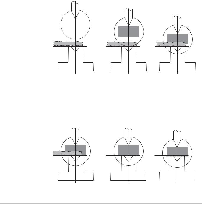
>Use gloves to prevent:
–Injuries caused by edges, corners and burr
–Residues and rust caused by sweat from the hands getting on dies and workpieces
–Deposits on the hands
–Slipping of smooth workpieces
Fig. 2: Handling of the workpiece 1
>Hold the sheet by the left and right corners of the end facing you.
>Use both hands to hold the sheet firmly from below (thumb on top of the sheet, rest of hand underneath)
Fig. 3: Handling of the workpiece 2
>When holding the sheet, be sure not to spread your fingers.
Note Spread fingers will interrupt the protective volume of the V4000 PB. The protective function of the V4000 PB will be triggered and the V4000 PB initiates a stop.
If the protective volume is limited (box-bending and back-stop operation) there will be an additional risk of getting your hand caught.
12 |
© SICK AG • Industrial Safety Systems • Germany • All rights reserved |
8010505/TL63/2009-11-27 |

Operating instructions |
On safety |
Chapter 2 |
V4000 PB |
|
|
Correct handling of pre-flanged sheets |
|
|
|
|
|
Fig. 4: Handling of |
|
|
|
|
|
pre-flanged sheets |
|
|
|
|
|
Note If pre-flanged sheets are not handled correctly, your hands could get caught between the sheet and the die or press crosshead.
>Hold the pre-flanged sheet by the left and right edges between the thumbs and index fingers.
>Use both hands to hold the sheet firmly.
8010505/TL63/2009-11-27 |
© SICK AG • Industrial Safety Systems • Germany • All rights reserved |
13 |
Chapter 2 |
On safety |
Operating instructions
V4000 PB
Correct handling with box-bending
Fig. 5: Handling of box-shaped workpieces
Note In box-bending and back-stop modes the protective volume is limited and a tolerance zone around the pressure axis is hidden. If box-like workpieces are not handled correctly, your hands could get caught between the workpiece and the die or press crosshead.
>Do not hold the upper box walls by the edges or corners on the pressure axis.
>Hold box-shaped workpieces by their back part (closest to you) outside the hazardous point.
The V4000 PB cannot protect you against these dangers:
Crushing your hands or fingers between the workpiece and the press crosshead as a result of handling the workpiece incorrectly during bending
Crushing your fingers between the die and the workpiece as a result of handling the workpiece incorrectly
The risk of injury from workpieces falling when the press brake is opened
The risk of injury from large workpieces swinging upwards during bending
When bending aids are used:
Risk of injury due to the workpiece swinging up or down, or to the movement of the bending aids
14 |
© SICK AG • Industrial Safety Systems • Germany • All rights reserved |
8010505/TL63/2009-11-27 |

Operating instructions |
On safety |
Chapter 2 |
V4000 PB
Note
When automatically traversing rear stops are used:
–Crushing your hands or fingers between the rear stops and the female die during traversing movements towards the operator
–The operator being crushed by large workpieces being pushed at him by the rear stops
Risk of injury in the rear space arising from automatically traversing stops, moving tools, workpieces or bending aids.
Access to the rear space or standing in the rear space must be prevented by means of the appropriate safety devices, such as a light grid.
Dangers arising from mounting of the V4000 PB
>When mounting the V4000 PB make sure that there will be no crushing or shearing points between the moving sender and receiver and other stationary machine parts or devices in the vicinity of the machine.
>If hazardous points cannot be avoided, they must be made safe by other protective measures or remedied by design changes.
8010505/TL63/2009-11-27 |
© SICK AG • Industrial Safety Systems • Germany • All rights reserved |
15 |

Chapter 2 |
On safety |
Operating instructions
Tab. 1: Overview of disposal by component
Note
a
WARNING
V4000 PB
2.6Environmental protection
The V4000 PB has been designed to minimise environmental impact. It uses only a minimum of power and natural resources.
>At work, always act in an environmentally responsible manner.
2.6.1Disposal
Disposal of unusable or irreparable devices should always occur in accordance with the applicable country-specific waste-disposal regulations
(e.g. European Waste Code 16 02 14).
Before you can turn over the devices for environmentally-friendly recycling, you must separate the different materials of the V4000 PB from one another.
>Separate the housing from the remaining components (especially the PCB).
>Press the front lens out of the lens holder.
>Send the separated components to the corresponding recycling centres (see Tab. 1).
Component |
Disposal |
Product |
|
Housing |
Metal recycling (aluminium) |
Front lens |
Glass recycling (used glass) |
PCBs, cables, plugs and |
Electronics recycling |
electrical connection pieces |
|
Packaging |
|
Cardboard, paper |
Paper/cardboard recycling |
Polyethylene packaging |
Plastic recycling |
|
|
We would be pleased to be of assistance on the disposal of the V4000 PB. Contact your local SICK representative.
Material separation may only be performed by specialist personnel!
Exercise care when disassembling the devices. The danger of injury is present.
16 |
© SICK AG • Industrial Safety Systems • Germany • All rights reserved |
8010505/TL63/2009-11-27 |
Operating instructions |
Product description |
Chapter 3 |
V4000 PB |
|
|
|
|
3 Product description
This chapter provides information on the special features and properties of the V4000 PB.
It describes the safety concept, the range of use, the structure and operating principle of the device, configuration options and the various operating modes.
>Read this chapter before you mount, install and commission the V4000 PB.
3.1Special features
Sender/receiver system
Response time 10 ms
Unambiguous status information via LED and 7-segment display shown directly on the V4000 PB receiver
All inputs and outputs of the system integrated in the receiver
Simple combination of the V4000 PB system with alternative protective measures by means of bypass inputs and outputs
No additional evaluation unit required in the control cabinet
V4000 PB system uses the existing measurement guides of the press brake for determining speed, position and direction
Optional operation via hardware input devices or via the outputs of the press brake controller (e.g. NC).
The SICK CDS user interface provides ease of configuration and comprehensive expanded diagnostics of the V4000 PB system
Reliable pinch-point monitoring even when workpiece surface has irregularities or unevenness
Automatic functions
Determination and monitoring of the pinch point
Monitoring of the relevant overall machine overrun of the press brake as a function of speed
Monitoring of the slow closing speed (≤ 10 mm/s) from pinch point V4000 PB (can be configured)
Dynamic adaptation of the switch-over point
Position-dependent muting (6 mm above the pinch point)
Speed-dependent muting (configurable)
Checking of the die position to detect coarse maladjustment
Detection of box wall in front and rear spaces
Protective operation
3 protective volume modes with adapted protective volume shape corresponding to bending task
Loading of press hydraulics minimised by box and back-stop modes without emergency stop at box wall
8010505/TL63/2009-11-27 |
© SICK AG • Industrial Safety Systems • Germany • All rights reserved |
17 |
Chapter 3 |
Product description |
Operating instructions
Fig. 6: Press brake with V4000 PB
V4000 PB
3.2Safety concept
3.2.1Protection principle of the V4000 PB
Press crosshead
Receiver
Die
Female die
Illumination field/ protective volume
Sender
The V4000 PB consists of a sender and a receiver mounted on the press crosshead.
A light beam of light (illumination field) between sender and receiver forms a threedimensional protective field (protective volume) beneath the die tip measuring 40 mm wide and 26 mm high. The protective volume follows the movement of the press crosshead and in this way provides a travelling safety zone beneath the die tip.
The V4000 PB has three different kinds of protective volume (standard, box and backstop). These protective volumes differ in their dimensions and in their functions.
Should there be a partial or complete interruption of the protective volume by an object, the output signal switching devices (OSSDs) of the ESPE which are integrated in the receiver change over to the OFF state and generate a two-channel monitored switch-off signal to the press controller which then must stop the closing movement of the press crosshead with the die.
The evaluation and run concepts of the V4000 PB have been designed so that the ESPE constantly checks its internal expected position (which depends on the operating mode, the press crosshead position and the speed) against the actual external situation. Only when the expected position is identical to the actual circumstances will the OSSDs remain in the ON state. Any other result will put the OSSDs into the OFF state.
18 |
© SICK AG • Industrial Safety Systems • Germany • All rights reserved |
8010505/TL63/2009-11-27 |
Operating instructions |
Product description |
Chapter 3 |
V4000 PB
Note
The V4000 PB safeguards the hazardous point beneath the die at high closing speeds
(> 10 mm/s) and a pass-through gap height of more than 6 mm. If the gap height between the top of the workpiece and the die tip is 6 mm or less, the ESPE switches automatically into muting mode.
If the muting option is activated at a low closing speed (≤ 10 mm/s), the system will automatically go into muting mode even when the slow closing speed is reached. The speed is monitored continuously.
In the muting state, the protective volume is inactive and the OSSDs stay in the ON state.
Whether muting is permitted at the slow closing speed varies from country to country. This option is by default disabled in the configuration.
In the event of system errors (such as an error being detected when the hardware is tested) the V4000 PB switches into lock-out state.
Fig. 7: Definitions
Die
Illumination field
Protective volume
Pressure axis
Workpiece
Female die
8010505/TL63/2009-11-27 |
© SICK AG • Industrial Safety Systems • Germany • All rights reserved |
19 |
Chapter 3 |
Product description |
Operating instructions
V4000 PB
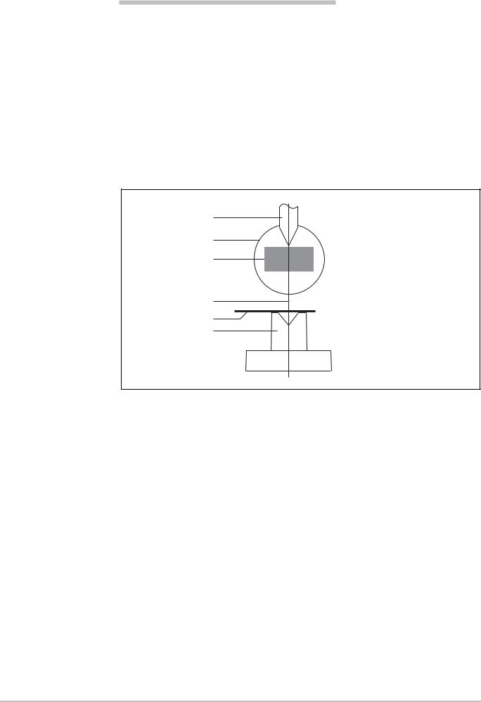
3.2.2Protective volume during the operating cycle
This sequence shows the protective volume during one operating cycle.
Step 1 The die is at the |
2 The die descends at |
3 At the switch-over point |
||
programmed top dead |
high speed |
the target speed is |
||
centre. |
(> 10 mm/s). |
requested by the |
||
The operator gives the |
The entire protective |
V4000 PB. |
||
signal to start the |
volume is active. |
The press controller |
||
closing movement (foot |
|
initiates the braking |
||
switch). |
|
procedure. |
||
|
|
|
|
The protective volume |
|
|
|
|
stays active in the gap |
|
|
|
|
opening. |
|
|
|
|
|
|
|
|
|
|
Protective volume
|
|
|
|
|
|
|
|
|
|
|
|
|
|
|
|
|
|
|
|
|
|
|
|
|
|
|
|
|
|
|
|
|
|
|
|
|
|
|
|
|
|
|
|
|
|
Step 4 The calculation of the |
5 The die contacts the |
6 The die shapes the |
||||||||||||||||||||
|
|
|
|
switch-over point |
|
|
workpiece (pinch point). |
|
workpiece. The |
|||||||||||||
|
|
|
|
includes an additional |
|
|
|
|
|
|
|
|
operating cycle ends at |
|||||||||
|
|
|
|
6 mm safety gap |
|
|
|
|
|
|
|
|
the programmed bottom |
|||||||||
|
|
|
|
required to reach the |
|
|
|
|
|
|
|
|
dead centre. The die |
|||||||||
|
|
|
|
target speed (vslow). |
|
|
|
|
|
|
|
|
goes back up. |
|||||||||
|
|
|
|
The protective volume |
|
|
|
|
|
|
|
|
|
|
|
|
|
|
||||
|
|
|
|
becomes inactive. |
|
|
|
|
|
|
|
|
|
|
|
|
|
|
||||
|
6 mm |
|
|
|
|
|
|
|
|
|
|
|
|
|
|
|||||||
|
|
|
|
|
|
|
|
|
|
|
|
|
|
|
|
|
|
|
|
|
|
|
|
|
|
|
|
|
|
|
|
|
|
|
|
|
|
|
|
|
|
|
|
|
|
|
|
|
|
|
|
|
|
|
|
|
|
|
|
|
|
|
|
|
|
|
|
|
|
|
|
|
|
|
|
|
|
|
|
|
|
|
|
|
|
|
|
|
|
|
|
|
|
|
|
|
|
|
|
|
|
|
|
|
|
|
|
|
|
|
|
|||
Protective volume |
|
|
|
|
|
|
|
|
|
|
|
|
|
|
|
|
|
|
|
|
||
|
|
|
|
|
|
|
|
|
|
|
|
|
|
|
|
|
|
|
||||
|
|
|
|
|
|
|
|
|
|
|
|
|
|
|
|
|
|
|
|
|
|
|
|
|
|
|
|
|
|
|
|
|
|
|
|
|
|
|
|
|
|
|
|
|
|
20 |
© SICK AG • Industrial Safety Systems • Germany • All rights reserved |
8010505/TL63/2009-11-27 |
Operating instructions |
Product description |
Chapter 3 |
V4000 PB |
|
|
|
|
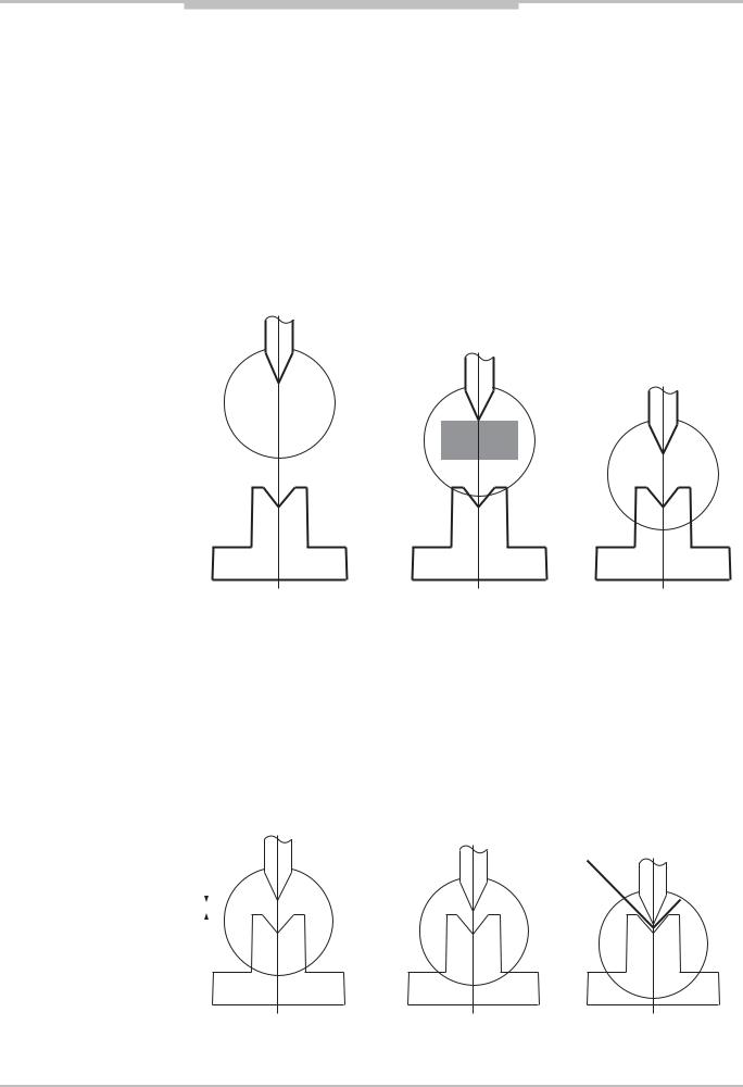
3.2.3Intrusion of the protective volume during the operating cycle
This sequence shows how the V4000 PB responds when there is an interruption to the
protective volume. |
|
|
||
Step 1 The die is at the |
2 The die descends at |
3 Part of the protective |
||
programmed top dead |
high speed |
volume is interrupted by |
||
centre. |
(> 10 mm/s). |
the object. |
||
There is a foreign object |
The entire protective |
The OSSDs go into the |
||
on the workpiece or |
volume is active. |
OFF state and generate |
||
female die. |
|
a safe stop signal. |
||
The operator gives the |
|
The press controller |
||
signal to start the |
|
must ensure the stop |
||
closing movement (foot |
|
procedure is |
||
switch). |
|
implemented. |
||
|
|
|
|
|
|
|
|
|
|
Protective volume
Step 4 The die continues to |
5 The object is now |
6 The operator gives the |
move in accordance |
removed. |
signal once more to |
with the overall machine |
The protective volume is |
start the closing |
overrun and stops at |
clear again. |
movement (foot switch). |
least 5 mm above the |
|
The closing movement |
object. |
|
starts and the operating |
|
|
cycle resumes. |
Protective volume
8010505/TL63/2009-11-27 |
© SICK AG • Industrial Safety Systems • Germany • All rights reserved |
21 |

Chapter 3 |
Product description |
Operating instructions
V4000 PB
3.3Range of use
The V4000 PB is an ESPE (electro-sensitive protective equipment) device designed to protect the area beneath the die of press brakes at high closing speeds, it provides hand and fingers protection.
The V4000 PB is suitable for stationary use in press brakes with a maximum distance of 7.5 m between the sender and the receiver.
The press brake must be designed to comply with the maximum stopping distance of 11 m.
This corresponds, for example, to a maximum overall machine overrun of 8.5 mm at a maximum closing speed of 300 mm/s (see also Section 3.5.13 "Monitoring of the slow closing speed vcrawl from the pinch point").
Requirements for use of the V4000 PB
Before the V4000 PB can carry out its protective functions the following conditions must be met:
It must be possible to influence the control of the press brake by electrical means.
The OSSDs of the V4000 PB must be incorporated into the press controller in such a way that when the OSSDs give the switch-off signal:
–the dangerous state (high closing speed of > 10 mm/s) is stopped.
or
–the press, should the lock-out state occur, does not start up again.
The V4000 PB must be mounted and configured in such a way that it can detect objects when they penetrate into the hazardous point.
22 |
© SICK AG • Industrial Safety Systems • Germany • All rights reserved |
8010505/TL63/2009-11-27 |

Operating instructions |
Product description |
Chapter 3 |
V4000 PB
Fig. 8: Components
Fig. 9: Sender and receiver
3.4Structure of the device
The V4000 PB comprises the following components:
Sender
Receiver with interfaces
PBI with interfaces
CDS (software for configuration and diagnostics of the V4000 PB sensor)
In addition the V4000 PB needs control signals from external operating elements. The sections which follow describe the individual components of the device.
|
NC |
|
PBI |
SPLC |
|
|
|
|
Incremental |
Incremental |
|
encoders |
encoders |
|
|
Operating |
|
|
elements |
|
|
HMI |
|
|
CDS |
Start |
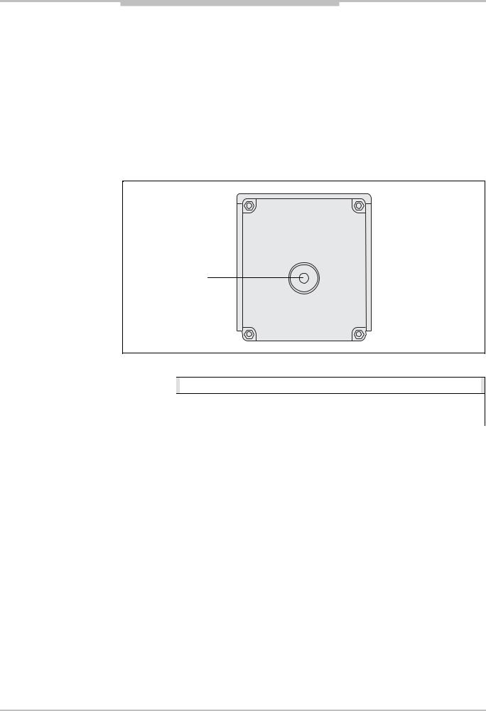
3.4.1Sender and receiver
Receiver |
LEDs |
7-segment display |
Sender |
LED |
Sender and receiver are mounted on the press crosshead and follow the movements of the crosshead. At start-up and every time there is a change of tooling, they need to be precisely aligned to the length of the die used and to each other.
8010505/TL63/2009-11-27 |
© SICK AG • Industrial Safety Systems • Germany • All rights reserved |
23 |
Chapter 3 |
Product description |
Operating instructions
V4000 PB
The laser diode in the sender emits light which is collected at the transmitting lens and given parallel alignment. The beam of light, which has a constant diameter of 58 mm (illumination field), travels along the lower side of the die to the receiver. In the receiver the light beam is mapped at the image detector.
The evaluation electronics with all relevant inputs and outputs is built into the receiver. Two output switching elements (OSSDs), which go into the OFF state when the sensor function is triggered, pass on the signal for stopping the closing movement (high closing speed > 10 mm/s).
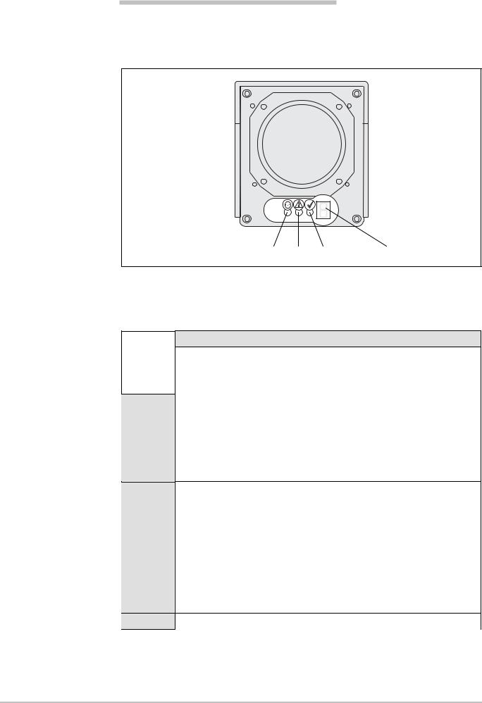
3.4.2Displays at the sender and receiver
Display at the sender
Fig. 10: Display at the sender
LED: Yellow
An LED on the sender displays the status.
Tab. 2: Display at the sender |
|
Display |
|
|
|
|
|
|
|
|
|
|
|
O Yellow |
|
Power supply OK. |
|
|
|
|
|
|
The sender of the V4000 PB is switched on. |
|
|
|
|
|
|
24 |
© SICK AG • Industrial Safety Systems • Germany • All rights reserved |
8010505/TL63/2009-11-27 |
Operating instructions |
Product description |
Chapter 3 |
V4000 PB
Fig. 11: Displays at the receiver
Tab. 3: Key to the LEDs on the receiver display
Displays at the receiver
The status of the system is displayed at the receiver by three LEDs and a 7-segment display.
LEDs: |
Red Yellow Green |
7-segment display |
The LEDs tell the operator whether an input is expected and whether the OSSDs are in the OFF or ON state.
The 7-segment display provides the operator with further information about the status of the V4000 PB.
Display |
|
Ö Yellow |
Operator action (input) is required (On % / Off % at 1 Hz) |
(10/90) |
– Alignment mode |
(90/10) |
– Teach-in request |
|
|
OYellow In production operation: Operator action (input) required
–In standard mode (release foot switch)
–In back-stop mode (first operation of the foot switch expected)
–In box mode (first operation of the foot switch expected)
During configuration: CDS connected and Configuration operating mode selected
O Red System sending signals to switch off the machine (OSSDs in the OFF state)
Additional states in which the red LED is illuminated:
–Self-test (system initialisation)
–Configuration
–Box mode
–Back-stop mode
–Lock-out state
–Alignment mode
O Green System free (OSSDs in the ON state)
8010505/TL63/2009-11-27 |
© SICK AG • Industrial Safety Systems • Germany • All rights reserved |
25 |

Chapter 3 |
Product description |
Operating instructions
Tab. 4: Key to the 7-segment display on the receiver
Note
V4000 PB
Display
6 System error. The device is defective. Replace the receiver.
MMuting state
`Switch on. This is followed by self-testing of the V4000 PB (system initialisation).
L Standard mode
=Box mode
}Back-stop mode
Other |
All of the other displays are error messages, displays within alignment |
displays |
mode or displays during the self-test (system initialisation). |
|
|
Further explanations of the 7-segment display will be found in the following sections:
Displays during system initialisation when the machine is switched on (see Section 8.1 "Switching the machine on")
Displays within alignment mode (see Section 7.2 "Aligning sender and receiver")
Error displays within lock-out state (see Section 9.2 "Error displays of the LEDs")
3.4.3Interfaces at the receiver
The receiver of the V4000 PB has the following interfaces:
Digital interface
Serial interfaces for configuration and diagnostics
Interface for connecting the sender
Interface for connecting the PBI
26 |
© SICK AG • Industrial Safety Systems • Germany • All rights reserved |
8010505/TL63/2009-11-27 |
Loading...