

Page 1

MODEL W1712
12" DISC &
6" BELT SANDER
OWNER'S MANUAL
(FOR MODELS MANUFACTURED SINCE 3/12)
Phone: (360) 734-3482 • Online Technical Support: techsupport@woodstockint.com
COPYRIGHT © AUGUST, 2003 BY WOODSTOCK INTERNATIONAL, INC. REVISED DECEMBER, 2016 (BL)
WARNING: NO PORTION OF THIS MANUAL MAY BE REPRODUCED IN ANY SHAPE OR FORM WITHOUT
175381
THE WRITTEN APPROVAL OF WOODSTOCK INTERNATIONAL, INC.
#5336 Printed in Taiwan
Page 2
This manual provides critical safety instructions on the proper setup,
operation, maintenance, and service of this machine/tool. Save this
document, refer to it often, and use it to instruct other operators.
Failure to read, understand and follow the instructions in this manual
may result in fire or serious personal injury—including amputation,
electrocution, or death.
The owner of this machine/tool is solely responsible for its safe use.
This responsibility includes but is not limited to proper installation in
a safe environment, personnel training and usage authorization,
proper inspection and maintenance, manual availability and comprehension, application of safety devices, cutting/sanding/grinding tool
integrity, and the usage of personal protective equipment.
The manufacturer will not be held liable for injury or property
damage from negligence, improper training, machine modifications or
misuse.
Some dust created by power sanding, sawing, grinding, drilling, and
other construction activities contains chemicals known to the State of
California to cause cancer, birth defects or other reproductive harm.
Some examples of these chemicals are:
• Lead from lead-based paints.
• Crystalline silica from bricks, cement and other masonry products.
• Arsenic and chromium from chemically-treated lumber.
Your risk from these exposures varies, depending on how often you
do this type of work. To reduce your exposure to these chemicals:
Work in a well ventilated area, and work with approved safety equipment, such as those dust masks that are specially designed to filter
out microscopic particles.
Page 3

Contents
INTRODUCTION .....................................2
Contact Info ....................................... 2
Manual Accuracy .................................. 2
Machine Specifications .......................... 3
Identification ..................................... 5
SAFETY ............................................... 6
Standard Machinery Safety Instructions ...... 6
Additional Safety for Combination Sanders .. 8
ELECTRICAL .........................................9
Circuit Requirements ............................9
Grounding Requirements ...................... 10
Extension Cords ................................ 10
SETUP .............................................. 11
Unpacking ....................................... 11
Inventory ........................................ 11
Shop Preparation ............................... 12
Dust Collection ................................. 12
Initial Cleaning ................................. 12
Cabinet Assembly .............................. 13
Mounting Sander ................................ 14
Installing Table ................................. 15
ACCESSORIES ...................................... 22
Combination Sander Accessories ............. 22
MAINTENANCE .................................... 23
General .......................................... 23
Table & Base .................................... 23
Sanding Surfaces ............................... 23
SERVICE ............................................ 24
General .......................................... 24
Belt Tracking .................................... 24
Table Angle Adjustment ....................... 25
Disc Table Alignment........................... 26
Troubleshooting ................................. 27
Electrical Safety Instructions ................. 29
Wiring Diagram ................................. 30
PARTS .............................................. 31
Main Breakdown ................................ 31
Base Breakdown ................................ 32
WARRANTY ........................................ 37
SAFETYINTRODUCTION
SET UPELECTRICAL MAINTENANCE
OPERATIONS....................................... 16
Test Run .......................................... 16
Power Switch ................................... 17
Belt/Disc Selection ............................ 17
Miter Sanding ................................... 17
Disc Sanding ..................................... 18
Flat Sanding ..................................... 18
Changing Sanding Belt ......................... 20
Changing Sanding Disc Paper ................. 21
OPERATIONS
SERVICE PARTS
USE THE QUICK GUIDE PAGE LABELS TO SEARCH OUT INFORMATION FAST!
Page 4
INTRODUCTION
We are proud to provide a high-quality owner’s
manual with your new machine!
We
the
instructions, specifications, drawings, and photographs contained inside. Sometimes we make
mistakes, but our policy of continuous improvement
machine
you receive will be slightly different than what
is shown in the manual
If you find this to be the case, and the difference
between the manual and machine leaves you
confused about a procedure
check our website
for an updated version. W
manuals
and
on our website at
www.
Alternatively, you can call our Technical Support
for help. Before calling, make sure you write
down the
from the machine ID label (see below). Also, if
available, have a copy of your original purchase
receipt on hand. This information is required for
all Tech Support calls.
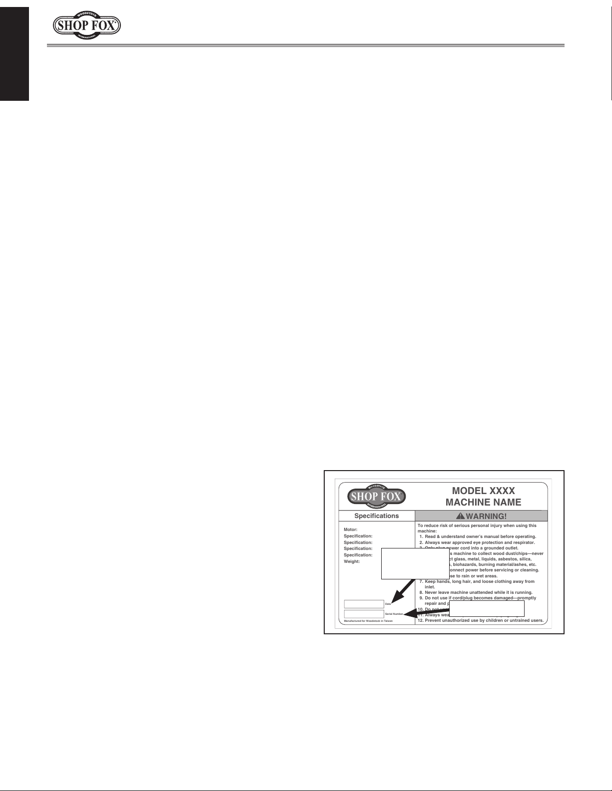
MODEL XXXX
MACHINE NAME
Motor:
Specification:
Specification:
Specification:
Specification:
Weight:
Specifications
To reduce risk of serious personal injury when using this
machine:
1. Read & understand owner’s manual before operating.
2. Always wear approved eye protection and respirator.
3. Only plug power cord into a grounded outlet.
4. Only use this machine to collect wood dust/chips—never
use to collect glass, metal, liquids, asbestos, silica,
animal parts, biohazards, burning material/ashes, etc.
5. Always disconnect power before servicing or cleaning.
6. Do not expose to rain or wet areas.
7. Keep hands, long hair, and loose clothing away from
inlet.
8. Never leave machine unattended while it is running.
9. Do not use if cord/plug becomes damaged—promptly
repair and protect cord from future damage.
10. Do not use without dust bag or filters in place.
11. Always wear a respirator when emptying bags.
12. Prevent unauthorized use by children or untrained users.
Date
Serial Number
Manufactured for Woodstock in Taiwan
WARNING!
We are committed to customer satisfaction. If
you have any questions or need help, use the
information below to contact us.
IMPORTANT: Before contacting, please get the
original purchase receipt, serial number, and
manufacture date of your machine. This information is required for all Technical Support
calls and it will help us help you faster.
We want your feedback on this manual. What did
you like about it? Where could it be improved?
Please take a few minutes to give us feedback.
Email: manuals@woodstockint.com
Model W1712 (For Machines Mfd. Since 3/12)
INTRODUCTION
Contact Info
Woodstock International Technical Support
Phone: (360) 734-3482
Email: techsupport@woodstockint.com
Technical Documentation Manager
P.O. Box 2309
Bellingham, WA 98227
Manual Accuracy
made every effort to be exact with
also means that sometimes the
.
,
e post current
manual updates for free
woodstockint.com.
Manufacture Date and Serial Number
Manufacture
Date
Serial Number
-2-
Page 5

Model W1712 (For Machines Mfd. Since 3/12)
MODEL W1712
11/2 HP 6" BELT / 12" DISK COMBINATION SANDER
Product Dimensions
Weight.......................................................................................................... 145 lbs.
Width (side‐to‐side) x Depth (front‐to‐back) x Height........................ 32‐1/2 x 16‐1/2 x 29‐1/2 in.
Footprint (Length x Width).............................................................................. 17 x 14 in.
Shipping Dimensions
Type.................................................................................................... Cardboard Box
Content........................................................................................................ Machine
Weight.......................................................................................................... 179 lbs.
Length x Width x Height........................................................................... 32 x 30 x 21 in.
INTRODUCTION
Electrical
Power Requirement.................................................................... 110V, Single‐Phase, 60 Hz
Prewired Voltage................................................................................................. 110V
Full‐Load Current Rating....................................................................................... 10.5A
Minimum Circuit Size............................................................................................. 15A
Connection Type......................................................................................... Cord & Plug
Power Cord Included.............................................................................................. Yes
Power Cord Length............................................................................................... 5 ft.
Power Cord Gauge............................................................................................ 14 AWG
Plug Included....................................................................................................... Yes
Included Plug Type............................................................................................... 5‐15
Switch Type............................................................. Toggle Safety Switch w/Removable Key
Motors
Main
Type......................................................................... TEFC Capacitor‐Start Induction
Horsepower.............................................................................................. 1.5 HP
Phase.............................................................................................. Single‐Phase
Amps....................................................................................................... 10.5A
Speed.................................................................................................. 1725 RPM
Power Transfer ................................................................................... Direct Drive
Bearings............................................................... Shielded & Permanently Lubricated
-3-
Page 6

Main Specifications
INTRODUCTION
Model W1712 (For Machines Mfd. Since 3/12)
Belt Sander Info
Sanding Belt Width........................................................................................ 6 in.
Sanding Belt Length...................................................................................... 48 in.
Sanding Belt Speed.................................................................................. 1066 FPM
Sanding Belt Tilt....................................................................................... 90 deg.
Table Length......................................................................................... 12‐3/8 in.
Table Width................................................................................................ 7 in.
Table Thickness............................................................................................ 1 in.
Table Tilt................................................................................ Left 0, Right 45 deg.
Max Height of Belt in Vertical Position.......................................................... 29‐1/2 in.
Belt Tension Release Type.................................................................... Quick Release
Platen Type........................................................................................... Cast Iron
Platen Length........................................................................................ 14‐1/2 in.
Platen Width............................................................................................... 6 in.
Disc Sander Info
Disc Diameter............................................................................................. 12 in.
Disc Speed............................................................................................ 1725 RPM
Disc Sandpaper Backing Type............................................................................. PSA
Table Length......................................................................................... 17‐5/8 in.
Table Width............................................................................................... 10 in.
Table Thickness............................................................................................ 1 in.
Table Tilt................................................................................ Left 0, Right 45 deg.
Construction Materials
Base................................................................................................. Sheet Metal
Table......................................................................................... Ground Cast Iron
Frame............................................................................................... Sheet Metal
Disc..................................................................... Computer Balanced Cast Aluminum
Miter Gauge............................................................ Die Cast Aluminum/Aluminum Bar
Paint Type/Finish............................................................................. Powder Coated
Other Related Info
Miter Gauge Slot Width................................................................................ 3/4 in.
Miter Gauge Slot Height............................................................................... 3/8 in.
Number of Dust Ports......................................................................................... 2
Dust Port Size...................................................................................... 2, 2‐1/2 in.
Other
Country of Origin ............................................................................................. Taiwan
Warranty ....................................................................................................... 2 Years
Approximate Assembly & Setup Time ................................................................. 45 Minutes
Serial Number Location ......................................................................... ID Label on Motor
ISO 9001 Factory .................................................................................................. Yes
Certified by a Nationally Recognized Testing Laboratory (NRTL) ......................................... Yes
Features
Two Precision‐Ground Cast‐Iron Tables
Quick Change Belt Release
Direct Ball Bearing Drive
Tables Tilt 0‐45 Degrees
Heavy‐Duty Miter Gauge
-4-
Page 7
Model W1712 (For Machines Mfd. Since 3/12)
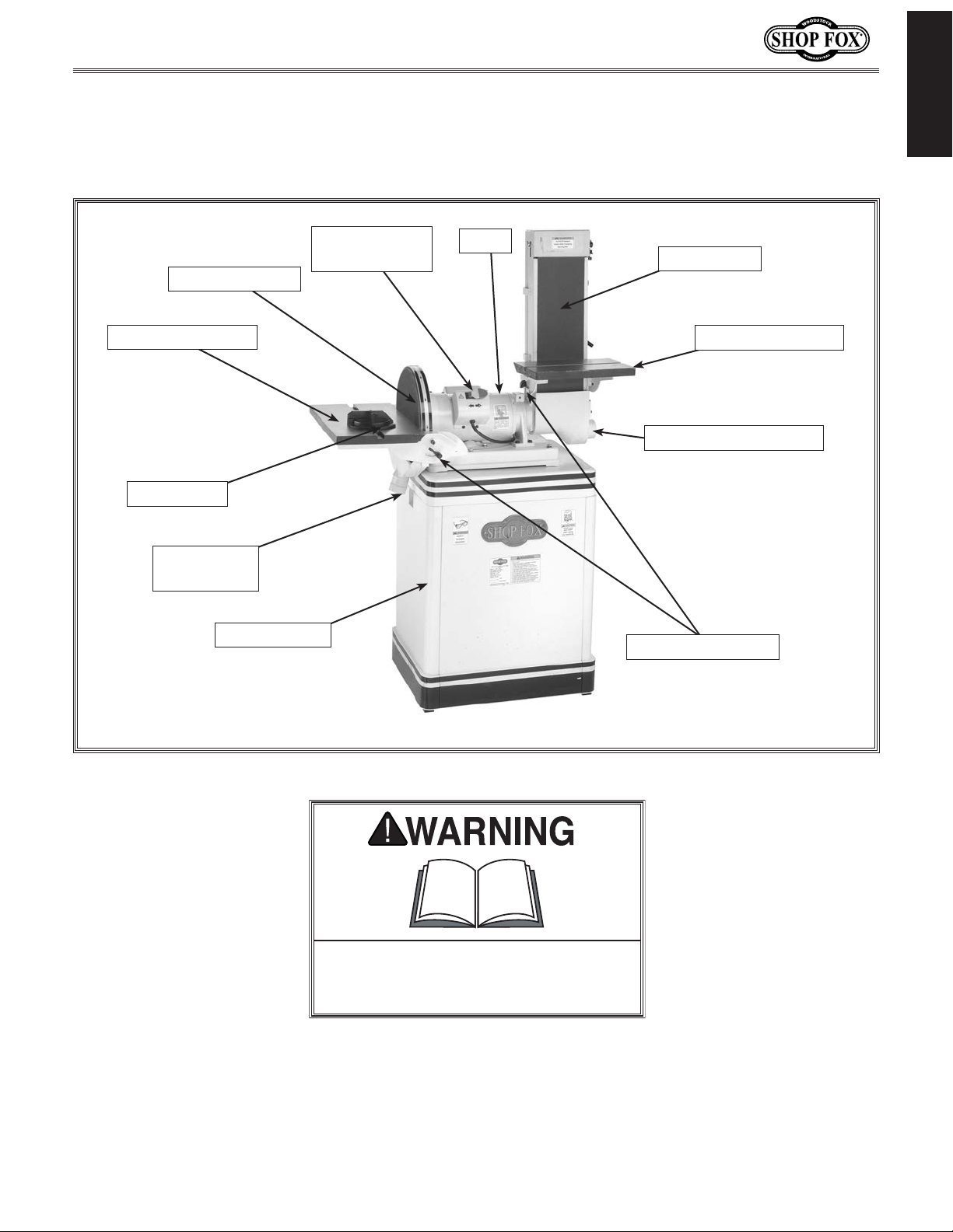
Become familiar with the names and locations of the controls and features shown below to better
Identification
INTRODUCTION
12" Sanding Disc
Sanding Disc Table
Miter Gauge
Sanding Disc
Dust Port
Cabinet Stand
Paddle Switch
w/Safety Key
Motor
Sanding Belt
Sanding Belt Table
Sanding Belt Dust Port
Table Tilting Knobs
Figure 1. Machine features.
To reduce your risk of serious injury
or damage to the machine, read this
entire manual BEFORE using machine.
-5-
Page 8

Model W1712 (For Machines Mfd. Since 3/12)
SAFETY
OWNER’S MANUAL.
TRAINED OPERATORS ONLY.
DANGEROUS ENVIRONMENTS.
MENTAL ALERTNESS REQUIRED.
electrical components or improperly grounded
manual uses a series of symbols and signal words intended to convey the level of importance of the
safety messages. The progression of symbols is described below. Remember that safety messages by
SAFETY
For Your Own Safety,
Read Manual Before Operating Machine
The purpose of safety symbols is to attract your attention to possible hazardous conditions. This
SAFETY
themselves do not eliminate danger and are not a substitute for proper accident prevention measures—this responsibility is ultimately up to the operator!
NOTICE
Standard Machinery Safety Instructions
Standard Machinery Safety Instructions
Indicates an imminently hazardous situation which, if not avoided,
WILL result in death or serious injury.
Indicates a potentially hazardous situation which, if not avoided,
COULD result in death or serious injury.
Indicates a potentially hazardous situation which, if not avoided,
MAY result in minor or moderate injury.
This symbol is used to alert the user to useful information about
proper operation of the equipment or a situation that may cause
damage to the machinery.
Read and understand this
owner’s manual BEFORE using machine.
have a higher risk of being hurt or killed. Only
allow trained/supervised people to use this
machine. When machine is not being used,
disconnect power, remove switch keys, or
lock-out machine to prevent unauthorized
use—especially around children. Make
workshop kid proof!
machinery in areas that are wet, cluttered,
or have poor lighting. Operating machinery
in these areas greatly increases the risk of
accidents and injury.
alertness is required for safe operation of
machinery. Never operate under the influence
of drugs or alcohol, when tired, or when
distracted.
Untrained operators
Do not use
Full mental
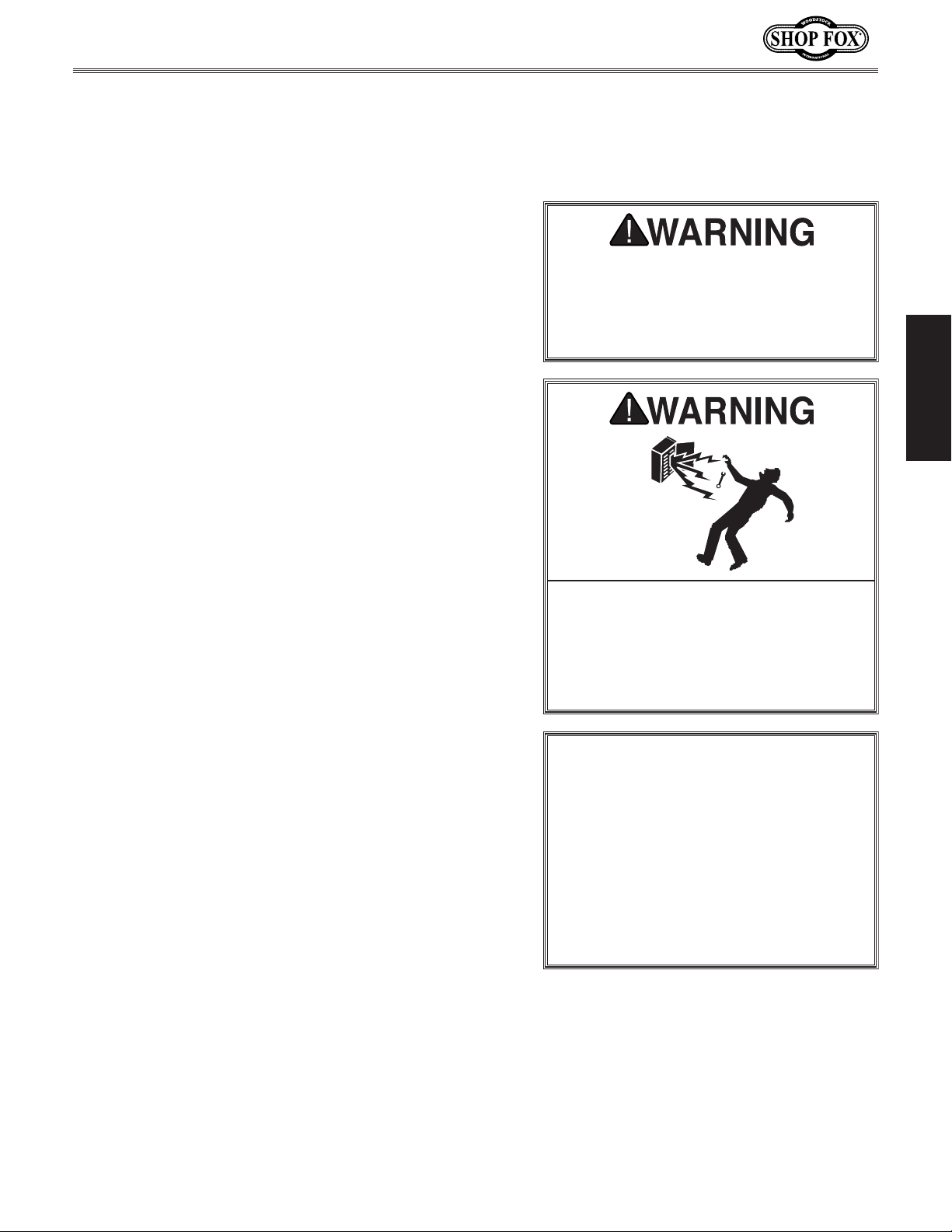
ELECTRICAL EQUIPMENT INJURY RISKS. You can
be shocked, burned, or killed by touching live
machinery. To reduce this risk, only allow an
electrician or qualified service personnel to
do electrical installation or repair work, and
always disconnect power before accessing or
exposing electrical equipment.
DISCONNECT POWER FIRST. Always disconnect
machine from power supply BEFORE making
adjustments, changing tooling, or servicing
machine. This eliminates the risk of injury
from unintended startup or contact with live
electrical components.
EYE PROTECTION. Always wear ANSI-approved
safety glasses or a face shield when operating
or observing machinery to reduce the risk of
eye injury or blindness from flying particles.
Everyday eyeglasses are not approved safety
glasses.
-6-
Page 9

Model W1712 (For Machines Mfd. Since 3/12)
WEARING PROPER APPAREL. Do not wear
HAZARDOUS
HEARING PROTECTION.
REMOVE ADJUSTING TOOLS.
INTENDED USAGE.
AWKWARD POSITIONS.
CHILDREN & BYSTANDERS.
GUARDS & COVERS.
FORCING MACHINERY. Do not force machine. It
will do the job safer and better at the rate for
loss of control. Before starting, verify machine
malfunction, leading to serious personal injury
from heated surfaces, high traffic areas, harsh
clothing, apparel, or jewelry that can become
entangled in moving parts. Always tie back
or cover long hair. Wear non-slip footwear to
avoid accidental slips, which could cause loss
of workpiece control.
DUST. Dust created while using
machinery may cause cancer, birth defects,
or long-term respiratory damage. Be aware of
dust hazards associated with each workpiece
material, and always wear a NIOSH-approved
respirator to reduce your risk.
Always wear hearing
protection when operating or observing
loud machinery. Extended exposure to this
noise without hearing protection can cause
permanent hearing loss.
machinery can become dangerous projectiles
upon startup. Never leave chuck keys,
wrenches, or any other tools on machine.
Always verify removal before starting!
intended purpose—never make modifications
without prior approval from Woodstock
International. Modifying machine or using
it differently than intended will void the
warranty and may result in malfunction or
mechanical failure that leads to serious
personal injury or death!
balance at all times when operating machine.
Do not overreach! Avoid awkward hand
positions that make workpiece control difficult
or increase the risk of accidental injury.
bystanders at a safe distance from the work
area. Stop using machine if they become a
distraction.
Only use machine for its
Tools left on
Keep proper footing and
Keep children and
which it was designed.
NEVER STAND ON MACHINE. Serious injury may
occur if machine is tipped or if the cutting
tool is unintentionally contacted.
STABLE MACHINE. Unexpected movement during
operation greatly increases risk of injury or
is stable and mobile base (if used) is locked.
USE RECOMMENDED ACCESSORIES. Consult
this owner’s manual or the manufacturer for
recommended accessories. Using improper
accessories will increase risk of serious injury.
UNATTENDED OPERATION. To reduce the risk
of accidental injury, turn machine OFF and
ensure all moving parts completely stop
before walking away. Never leave machine
running while unattended.
MAINTAIN WITH CARE. Follow all maintenance
instructions and lubrication schedules to
keep machine in good working condition. A
machine that is improperly maintained could
or death.
CHECK DAMAGED PARTS. Regularly inspect
machine for any condition that may affect
safe operation. Immediately repair or replace
damaged or mis-adjusted parts before
operating machine.
MAINTAIN POWER CORDS. When disconnecting
cord-connected machines from power, grab
and pull the plug—NOT the cord. Pulling the
cord may damage the wires inside, resulting
in a short. Do not handle cord/plug with wet
hands. Avoid cord damage by keeping it away
chemicals, and wet/damp locations.
SAFETY
accidental contact with moving parts or flying
debris—make sure they are properly installed,
undamaged, and working correctly.
Guards and covers reduce
EXPERIENCING DIFFICULTIES. If at any time
you experience difficulties performing the
intended operation, stop using the machine!
-7-
Contact Technical Support at (360) 734-3482.
Page 10

Model W1712 (For Machines Mfd. Since 3/12)
pieces can result in loss of control, resulting in
Additional Safety for Combination Sanders
Serious injury or death can occur if fingers, clothing, jewelry, or hair get entangled in moving
components. Impact injuries can occur from kickback if workpiece is improperly fed into moving
sandpaper. Serious pinch injuries can occur from touching in-running nip point between table and
SAFETY
sanding surface. Long-term respiratory damage can occur from using sander without proper use
of a respirator. To reduce the risk of these hazards, operator and bystanders MUST completely
heed the hazards and warnings below.
SANDPAPER DIRECTION. Feeding workpiece
incorrectly can cause it to be thrown from
machine, striking operator or bystanders, or causing your hands to slip into the moving sandpaper.
To reduce these risks, only sand against direction
of sandpaper travel, ensure workpiece is properly
supported, and avoid introducing sharp edges into
moving sandpaper on leading side of workpiece.
HAND PLACEMENT. Rotating sandpaper can
remove a large amount of flesh quickly. Always
keep hands away from sandpaper during operation. Never touch moving sandpaper on purpose.
Use a brush to clean table of sawdust and chips.
FEEDING WORKPIECE. Forcefully jamming workpiece into sanding surface could cause it to be
grabbed aggressively, pulling hands into sanding
surface. Firmly grasp workpiece in both hands and
ease it into sandpaper using light pressure.
AVOIDING ENTANGLEMENT. Becoming entangled
in moving parts can cause pinching and crushing
injuries. To avoid these hazards, keep all guards
in place and closed. DO NOT wear loose clothing,
gloves, or jewelry, and tie back long hair.
WORKPIECE SUPPORT. Workpiece kickback can
occur with violent force if workpiece is not properly supported during operation. Always sand
with workpiece firmly against table or another
support device.
WORKPIECE INSPECTION. Nails, staples, knots,
or other imperfections in workpiece can be dislodged and thrown from sander at a high rate of
speed at people, or cause damage to sandpaper
or sander. Never sand stock that has embedded
foreign objects or questionable imperfections.
SANDPAPER CONDITION. Worn or damaged sandpaper can fly apart and throw debris at operator,
or aggressively grab workpiece, resulting in subsequent injuries from operator loss of workpiece
control. Always inspect sandpaper before operation and replace if worn or damaged.
IN-RUNNING NIP POINTS. The gap between
moving sandpaper and fixed table/support creates a pinch point for fingers or workpieces; the
larger this gap is, the greater the risk of fingers or
workpieces getting caught in it. Minimize this risk
by adjusting table/support to no more than
away from sandpaper. For spindle sanders, always
use the table insert that fits closest diameter of
installed drum.
MINIMUM STOCK DIMENSION. Small workpieces
can be aggressively pulled from your hands, causing contact with sanding surface. Always use a
jig or other holding device when sanding small
workpieces, and keep hands and fingers at least
2" away from sanding surface.
WORKPIECE INTEGRITY. Sanding fragile work-
1
⁄16"
SANDING DUST. Sanding creates large amounts
of dust that can lead to eye injury or respiratory
illness. Reduce risk by wearing approved eye and
respiratory protection when using sander. Never
operate without adequate dust collection system
in place and running. Dust collection is not a substitute for using a respirator.
abrasion injuries, impact injuries, or damage to
sandpaper. Only sand solid workpieces that can
withstand power sanding forces. Make sure workpiece shape is properly supported; avoid sanding
workpieces without flat bottom surfaces unless
some type of jig is used to maintain support and
control when sanding force is applied.
-8-
Page 11
Model W1712 (For Machines Mfd. Since 3/12)
This machine must be connected to the correct size and
type of power supply circuit, or fire or electrical damage
may occur. Read through this section to determine if an
adequate power supply circuit is available. If a correct
circuit is not available, a qualified electrician MUST install
one before you can connect the machine to power.
A power supply circuit includes all electrical equipment
between the breaker box or fuse panel in the building
and the machine. The power supply circuit used for
this machine must be sized to safely handle the fullload current drawn from the machine for an extended
period of time. (If this machine is connected to a circuit
protected by fuses, use a time delay fuse marked D.)
This machine is prewired to operate on a power supply
circuit that has a verified ground and meets the following
requirements:
The full-load current rating is the amperage a machine
draws at 100% of the rated output power. On machines
with multiple motors, this is the amperage drawn by the
largest motor or sum of all motors and electrical devices
that might operate at one time during normal operations.
or machine damage. To reduce this risk,
a dedicated circuit—
where only one machine will be running
multiple machines will be running at the
ELECTRICAL
Circuit Requirements
The machine must be properly set up
before it is safe to operate. DO NOT
connect this machine to the power
source until instructed to do so later in
this manual.
ELECTRICAL
Full-Load Current Rating
Full-Load Current Rating at 110V ................10.5 Amps
Circuit Requirements for 110V
Circuit Type ............... 110V/120V, 60 Hz, Single-Phase
Circuit Size ............................................. 15 Amps
Plug/Receptacle .................................... NEMA 5-15
Incorrectly wiring or grounding this
machine can cause electrocution, fire,
only an electrician or qualified service
personnel should do any required
electrical work on this machine.
NOTICE
The circuit requirements listed in this
manual apply to
at a time. If this machine will be
connected to a shared circuit where
same time, consult with an electrician
to ensure that the circuit is properly
sized for safe operation.
-9-
Page 12
Grounding Requirements
This machine MUST be grounded. In the event of certain
types of
a path of least resistance for electric current
order
Improper connection of the equipment-grounding
will
increase
insulation
grounding
cord or plug is necessary, do not connect the equipmentgrounding
Check with a qualified electrician or service personnel
if
or if
properly grounded.
plug is damaged or worn, disconnect it from power, and
immediately replace it with a new one.
We do not recommend using an extension cord with
Any extension cord used with this machine must contain a
plug and receptacle, and
meet the following requirements:
This machine is equipped with a power cord with an
equipment-grounding
plug
a matching
grounded in accordance with local codes and ordinances.
Model W1712 (For Machines Mfd. Since 3/12)
malfunctions or breakdowns, grounding provides
to reduce the risk of electric shock.
the risk of electric shock. The wire with green
(with/without yellow stripes) is the equipment-
wire. If repair or replacement of the power
wire to a live (current carrying) terminal.
you do not understand these grounding requirements,
you are in doubt about whether the tool is
ELECTRICAL
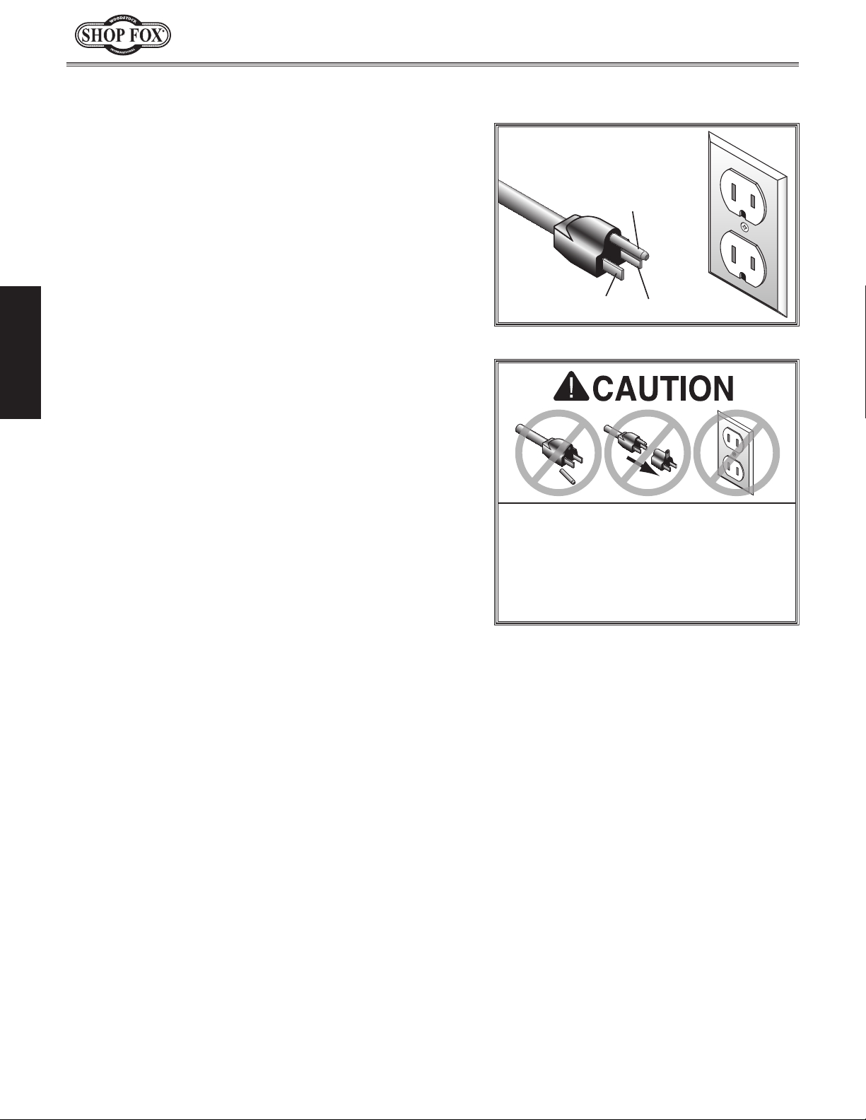
For 110V Connection
(see figure). The plug must only be inserted into
receptacle that is properly installed and
to travel—in
wire
If you ever notice that a cord or
wire and NE M A 5-15 grounding
110V
5-15 PLUG
Figure 2. NEMA 5-15 plug & receptacle.
DO NOT modify the provided plug or
use an adapter if the plug will not
fit the receptacle. Instead, have an
electrician install the proper receptacle
on a power supply circuit that meets
the requirements for this machine.
GROUNDED
5-15 RECEPTACLE
Grounding Prong
Neutral Hot
Extension Cords
this machine. Extension cords cause voltage drop, which
may damage electrical components and shorten motor
life. Voltage drop increases with longer extension cords
and smaller gauge sizes (higher gauge numbers indicate
smaller sizes).
ground wire, match the required
Minimum Gauge Size at 110V ...................... 14 AWG
Maximum Length (Shorter is Better) ................50 ft.
-10-
Page 13

Model W1712 (For Machines Mfd. Since 3/12)
This machine has been carefully packaged for safe
transportation. If you notice the machine has been
damaged during shipping, please contact your authorized
Shop Fox dealer immediately.
The following is a list of items shipped with your machine.
Before beginning setup, lay these items out and inventory
them.
Note:
check around/inside the machine and packaging materials.
Often, these items get lost in packaging materials while
unpacking or they are pre-installed at the factory.
Immediately discard all
materials to eliminate
SETUP
Unpacking
Inventory
If you cannot find an item on this list, carefully
Keep machine disconnected from
power until instructed otherwise.
A. Sander Unit .................................................1
B. Cabinet Stand ..............................................1
• Side Panel L/R ...........................................2
• Front/Rear Panel ........................................2
C. Table Hardware Bag .......................................1
5
— Cap Screw
— Lock Nut
— Flat Washer
⁄16"-18 x 3⁄4" ...............................2
5
⁄16"-18.........................................2
1
⁄4" ..........................................2
— Knob Bolt M6-1 x 15 ....................................2
D. 12" Disc Sanding Table ....................................1
E. Belt Sanding Table .........................................1
F. Main Hardware Bag ....................................... 1
• Cabinet Stand Hardware Bag ..........................1
5
—Hex Bolt
—Hex Bolt
—Hex Nut
—Flat Washer
—Lock Washer
⁄16"-18 x 3⁄8" .............................8
5
⁄16"-18 x 1" ...............................2
5
⁄16" .........................................8
5
⁄16" .................................. 18
5
⁄16" ................................. 10
—6MM Allen Wrench ..................................1
• Floor Pad Bag ............................................1
—Floor Pads ............................................4
3
—Phillips Head Screw
5
—Flat Washer
—Hex Nut
⁄16" ....................................4
5
⁄16" .........................................4
⁄16"-18 x 5⁄8" ................4
—Flat Washers 6mm .................................6
• Accessories Bag ..........................................1
—Belt Tension Lever ..................................1
—Screwdriver ..........................................1
—Knob Bolt M8-1.25 x 20 ............................1
—Stop Fence ...........................................1
G. Miter Gauge Assembly ......................................1
-11-
SETUP
USE helpers or power
lifting equipment to lift
this machine. Otherwise,
serious personal injury
may occur.
A
D
F
C
E
G
Figure 3. Inventory.
SUFFOCATION HAZARD!
plastic bags and packing
choking/suffocation
hazards for children and
animals.
B
Page 14

Model W1712 (For Machines Mfd. Since 3/12)
Shop Preparation
ONLY ALLOW TRAINED
PEOPLE in your shop! Make
sure shop entrances are
locked and machines are
correctly turned off with
lock-out devices when not
in use. Otherwise, injury
or death can occur.
• Lighting: Lighting should be bright enough
to eliminate shadows and prevent eye
strain.
• Working Clearances: Consider your current
and future shop needs with respect to the
safe operation of this machine.
• Outlets: Make sure the electrical circuits
SETUP
have the capacity to handle the amperage
requirements for your Model W1712. Refer
to Page 9 for more information. Electrical
outlets should be located near the sander,
so power or extension cords are clear of
high-traffic areas.
Dust Collection
Initial Cleaning
The exposed and unpainted sander surfaces are
coated with a waxy oil to prevent rust during
storage and shipment. DO NOT use chlorine
based solutions or solvents to remove this waxy
oil or you will damage the painted surfaces.
Remove the waxy oil with a solvent based
degreaser before you use the sander. Always
follow all usage and safety instructions of the
product that you are using.
DO NOT use flammables
such as gas or other
petroleum-based solvents
to clean your machine.
These products have low
flash points and present
the risk of explosion and
severe personal injury!
DO NOT smoke while
using cleaning solvents.
Smoking may cause
explosion or risk of fire
when exposed to these
products!
Some wood dust may
cause allergic reactions
or respiratory illness. Use
a dust collection system
and respirator in your
shop to help protect
yourself from these longterm hazards.
For information on the correct dust collection
components for sanders, contact your
Woodstock International dealer for a copy of
the Dust Collection Basics handbook and available accessories.
ALWAYS work in wellventilated areas far from
possible ignition sources
when using solvents to
clean machinery. Many
solvents are toxic when
inhaled or ingested. Use
care when disposing
of waste rags and
towels to be sure they
DO NOT create fire or
environmental hazards.
-12-
Page 15

Model W1712 (For Machines Mfd. Since 3/12)
Cabinet Assembly
The Model W1712 mounts onto a heavy-duty formed sheet
steel cabinet stand. Use the hardware in the cabinet
hardware bag to complete this assembly.
To assemble the cabinet stand, do these steps:
1. Assemble the cabinet panels together as shown in
Figure 4 with the supplied
5
⁄16" flat washers, 5⁄16" lock washers and 5⁄16" hex
nuts.
2. Attach the remaining side panel.
3. Secure the rubber feet to the bottom corners of the
cabinet stand with the floor pad hardware bag as
shown in Figure 5.
5
⁄16"-18 x 3⁄4" hex bolts,
Mounting Locations
Front/Rear Panels
Figure 4. Cabinet assembly.
Side Panel
SETUP
-13-
Figure 5. Rubber feet installed.
Page 16

Mounting Sander
Mounting the sander to the stand will require the help of
an assistant. Secure the sander to the stand using the
cabinet stand hardware bag.
To mount the sander, do these steps:
1. KEEP THE SANDER UNPLUGGED!
2. Place the sander on the stand.
3. Align the holes in the cabinet with the pre-drilled
and tapped mounting holes in the sander.
4. Secure the sander to the stand as shown in Figure 6.
Model W1712 (For Machines Mfd. Since 3/12)
USE helpers or power
lifting equipment to lift
this machine. Otherwise,
serious personal injury
may occur.
UNPLUG sander before you do any
assembly! Otherwise, serious person-
SETUP
al injury to you or others may occur!
Figure 6. Mounting the sander.
-14-
Page 17

Model W1712 (For Machines Mfd. Since 3/12)
Installing Table
The sanding belt table comes assembled on the W1712,
but the sanding disc table needs to be installed on the
sander.
To install the sanding disc table, do these steps:
1. KEEP THE SANDER UNPLUGGED!
2. Align the sanding table mounting holes with the
threaded holes in the bracket.
3. Secure the sanding table, as shown in Figure 7, with
the cap screws supplied in the table hardware bag.
4. Install the table tilt control knobs (Figure 8).
Figure 7. Installing table.
SETUP
Figure 8. Installed tilting knobs.
-15-
Page 18

OPERATIONS
If you are an inexperienced operator, we
or trade articles, or seek training from
machinery before performing unfamiliar
Test Run
The purpose of a test run is to identify any unusual noises and vibrations, as well as to confirm that the machine
is performing as intended.
To test run the Model W1712, do these steps:
1. Make sure all guards are in place.
Model W1712 (For Machines Mfd. Since 3/12)
2. Make sure that the ON/OFF switch is in the “OFF”
position before connecting the machine to power.
3. Pull the power switch up to start the sander. Once
the sander is running, listen for any unusual noises.
The machine should run smoothly with little or no
vibrations.
• If there are any unusual noises or vibrations, STOP
the sander immediately by pushing the paddle
switch down.
4. Unplug the sander and investigate the source of the
noise or vibration. DO NOT make any adjustments to
the sander while it is plugged in. The sander should
not be run any further until the problems are corrected.
OPERATIONS
To reduce your risk of serious injury
or damage to the machine, read this
entire manual BEFORE using machine.
To reduce the risk of eye injury and
long-term respiratory damage, always
wear safety glasses and a respirator
while operating this machine.
Tie back long hair, roll
up long sleeves, and
remove loose clothing,
jewelry, or gloves to
prevent getting caught
in moving parts.
strongly recommend that you read books
an experienced operator of this type of
operations. Above all, safety must come
first!
-16-
Page 19

Model W1712 (For Machines Mfd. Since 3/12)
Power Switch
The power switch on the SHOP FOX® Model W1712 not
only starts and stops the sander, but features a safety
lockout key. When the key is removed, as shown in
Figure 9, the sander is disabled to prevent accidental
start up.
Belt/Disc Selection
Figure 9. Safety lockout key removed.
The SHOP FOX® Model W1712 accepts 6" x 48" sanding
belts and 12" discs. There are a large variety of sanding
belts and discs to choose from. We recommend Aluminum
Oxide belts and discs for standard sanding purposes.
Figure 10 shows abrasive types and grit numbers.
As a general rule of thumb, progressively increase the
grit number you use without jumping more than 50 grit
sizes at one time.
Miter Sanding
The most efficient way to get a perfect miter is to cut
the workpiece slightly long and sand it to the desired
dimension. Miter sanding can be done easily with the
miter gauge:
To perform miter sanding operations:
1. Loosen the knob on the miter gauge and adjust the
angle to the desired point. Tighten the knob.
2. Slide the miter gauge into its slot in the table to
steady your workpiece at the correct angle. Note—
The miter gauge can be used in either direction in
the slot to achieve the proper relation of the
workpiece to the disc.
Type Grit
Coarse 60
Medium 80-100
Fine 120-180
Very Fine 220
Figure 10. Abrasive types and grits.
OPERATIONS
Figure 11. Miter sanding operation.
3. Hold the workpiece and miter gauge firmly as shown
in Figure 11.
-17-
Page 20

Disc Sanding
To start disc sanding operations, do these steps:
1. UNPLUG THE SANDER!
2. Set the table tilt angle to the desired position by
loosening the table lock knobs. Figure 12 shows the
table at 45˚.
3. Plug the sander into the power supply.
4. Start the sander.
5. Hold the workpiece firmly in both hands as shown in
Figure 13 Note— Always keep the workpiece on the
side of the wheel that is rotating down toward the
table. This will keep the workpiece from flying out
of your hands from the rotational forces.
Model W1712 (For Machines Mfd. Since 3/12)
Figure 12. Table tilt set at 45˚.
Flat Sanding
Flat sanding operations can be performed with the sanding belt in the vertical position or horizontal position.
To start flat sanding operations with the belt vertical,
do these steps:
1. UNPLUG THE SANDER!
2. Make sure the sanding table is square to the belt.
OPERATIONS
3. Plug the sander into the power supply.
4. Start the sander.
5. Hold the workpiece firmly as shown in Figure 14.
Figure 13. Disc sanding.
-18-
Figure 14. Flat sanding operation.
Page 21

Model W1712 (For Machines Mfd. Since 3/12)
To start flat sanding operations with the belt horizontal, do these steps:
1. UNPLUG THE SANDER!
2. Remove the belt sanding table.
3. Loosen the cap screw shown in Figure 15 to allow
the sanding belt to rotate.
4. Rotate the belt to the horizontal position then tighten the cap screw loosened in step 3.
5. Install the work-stop fence (shown in Figure 16) to
prevent the workpiece from running off the end of
the sander.
6. Start the sander.
7. Hold the workpiece firmly and in contact with the
work-stop fence as shown in Figure 17.
Cap Screw
Figure 15. Cap screw location.
Work-
Stop
Fence
Figure 16. Flat sanding operation.
Figure 17. Flat sanding operation.
OPERATIONS
-19-
Page 22

Changing Sanding Belt
ACCIDENTAL START-UP HAZARD!
UNPLUG the power cord when
making any adjustments on this
machine! Otherwise, serious personal injury to you or others may
occur!
To change the sanding belt, do these steps:
1. UNPLUG THE SANDER!
Model W1712 (For Machines Mfd. Since 3/12)
2. Remove all the cover lock knobs from the back of
the belt guard and slide the belt guard up and off
the sanding belt as shown in Figure 18.
3. Remove the table and mounting bracket from the
belt sander (Figure 19).
4. Release the belt tension by moving the belt tension
lever to the “unlock” position.
5. Roll the old sanding belt off the right side of the
rollers.
6. Install a new belt with the arrows in the proper
direction as shown in Figure 20.
OPERATIONS
7. Re-install the mounting bracket, table and belt
guards.
Figure 18. Removing belt guard.
Table and Mounting
Bracket
Figure 19. Table and mounting bracket.
-20-
Figure 20. Installing a new sanding belt.
Page 23

Model W1712 (For Machines Mfd. Since 3/12)
Changing Sanding Disc
Paper
The 12" disc sander requires 12" sanding discs with adhesive backing that can be easily attached to the disc.
To install a new sanding disc on the 12" disc sanding
surface:
1. UNPLUG THE SANDER!
2. Remove the disc sanding table.
3. Peel the old sanding paper off the sanding disc.
4. Place the new 12" sandpaper on the sanding disc as
shown in Figure 21.
5. Replace the disc sanding table.
UNPLUG the power cord when making
any adjustments during operation!
Otherwise, serious personal injury to
you or others may occur!
OPERATIONS
Figure 21. Sanding disc installation.
-21-
Page 24

Model W1712 (For Machines Mfd. Since 3/12)
ACCESSORIES
Combination Sander Accessories
The following Combination Sander accessories may be available through your local Woodstock
International Inc. Dealer. If you do not have a dealer in your area, these products are also available
through online dealers. Please call or e-mail Woodstock International Inc. Customer Service to get a
current listing of dealers at: 1-800-840-8420 or at sales@woodstockint.com.
Replacement 6" x 48" Aluminum Oxide Sanding Belts (2-Pk.)
D1256 60 Grit
D1257 80 Grit
D1258 100 Grit
D1259 120 Grit
D1260 150 Grit
D1261 180 Grit
D1262 220 Grit
Replacement 12" Aluminum Oxide PSA Sanding Discs (2-Pk.)
D1335 60 Grit
D1336 80 Grit
D1337 100 Grit
D1338 120 Grit
D1339 150 Grit
D13 40 180 Grit
D13 41 220 Grit
D3757—Universal Mobile Base
Can be customized to fit any size machine base with your own cutto-size plywood. Sturdy corner brackets attach with through-bolts for
OPERATIONS
tremendous strength. Kick-stand casters provide easy mobility, and
the adjustable feet provide stability during stationary machine use.
Accepts
caster brackets and two swivel caster brackets. 600 lb. max. capacity
PRO-STIK® Crepe-Rubber Belt Cleaners
Quickly remove gum and grit from belts, sleeves and discs without
damage. Extend the life of your belts, sleeves or discs with this
innovative natural cleaner.
1
⁄2"-11⁄2" thick plywood (not included). Includes two fixed
1
W1306—1
W1307—2" x 2" x 12"
W1304—1
W1305—1
⁄2" x 11⁄2" x 81⁄2"
3
⁄8" x 13⁄8" x 41⁄4"
3
⁄8" x 13⁄8" x 81⁄2"
-22-
Page 25

Model W1712 (For Machines Mfd. Since 3/12)
MAINTENANCE
General
For optimum performance from your machine, follow
this maintenance schedule and refer to any specific
instructions given in this section.
• Loose mounting bolts.
• Worn switch.
• Worn or damaged cords and plugs.
• Any other condition that could hamper the safe
operation of this machine.
Table & Base
Cleaning the Model W1712 is relatively easy. Vacuum excess
wood chips and sawdust, and wipe off the remaining dust
with a dry cloth. If any resin has built up, use a resin
dissolving cleaner to remove it.
Protect the unpainted cast iron tables by wiping them
clean after every use—this ensures moisture from wood
dust does not remain on bare metal surfaces. Keep your
tables rust-free with regular applications of quality
lubricants.
Sanding Surfaces
Regularly clean your sanding belt and disc as sawdust
builds up in the grit. Clean the sanding belts and discs
with PRO STICK
Cleaning built-up sawdust will prolong the life of your
sanding belts and discs.
®
belt cleaners as shown in Figure 22.
MAKE SURE that your machine is
unplugged during all maintenance
procedures! If this warning is ignored,
serious personal injury may occur.
Figure 22. Cleaning the sanding belt with
PRO STICK
®
.
MAINTENANCE
-23-
Page 26

General
This section covers the most common service adjustments
or procedures that may need to be made during the life
of your machine.
If you require additional machine service not included
in this section, please contact Woodstock International
Technical Support at (360) 734-3482 or send e-mail to:
techsupport@woodstockint.com.
Model W1712 (For Machines Mfd. Since 3/12)
SERVICE
Belt Tracking
The belt tracking must be adjusted correctly to make the
belt ride parallel with the table.
To adjust the belt tracking, do these steps:
1. UNPLUG THE SANDER!
2. Make sure all guards are in place and the belt lock-
ing lever is in the locked position as shown in
Figure 23.
3. Loosen the knurled adjustment nut away from the
roller pin (Figure 24).
4. Check the current belt position and note if it needs
to move left or right. Figure 25 shows a properly
tracked belt with
side.
5. Adjust the tension bolt clockwise to make the belt
ride to the left, and adjust counter-clockwise to
make the belt ride to the right.
1
⁄16" of the roller exposed on each
MAKE SURE that your machine is
unplugged during all service procedures! If this warning is ignored, serious personal injury may occur.
Locking Lever
Figure 23. Belt locking lever.
Adjustment Nut
Tension Bolt
Roller Pin
6. Plug in the sander.
7. Start the sander and observe the corrected belt
tracking.
8. Stop the sander and repeat steps 1-7 until the
SERVICE
desired tracking has been met.
9. Finger tighten the adjustment nut against the roller
pin when the belt is riding correctly.
-24-
Figure 24. Tracking adjustment system.
1
⁄16"
Clearance
Figure 25. Proper belt tracking (guard
removed for clarity).
Page 27

Model W1712 (For Machines Mfd. Since 3/12)
Table Angle Adjustment
The scale pointers on the sander indicate the tilt angle
of the sanding tables. The pointers have been set at the
factory but throughout the life of your machine, you may
need to adjust them.
To adjust the scale pointers, do these steps:
1. UNPLUG THE SANDER!
2. Loosen the table tilting lock knob shown in Figure
26 and rotate the table so it is perpendicular with
the edge of the sanding disc.
3. Place a machinist square on the disc sanding table
and against the sanding disc to check for squareness
(shown in Figure 27).
4. Lock the table tilt knob when the table is perpendicular to the disc.
UNPLUG the power cord when making
any adjustments during operation!
Otherwise, serious personal injury to
you or others may occur!
Tilting Knob
5. Loosen the screw securing the pointer and adjust it
so it indicates 90˚(Figure 27).
6. Repeat steps 1-5 to adjust the belt sanding table.
Figure 26. Table tilting knob.
Scale
Pointer
SERVICE
-25-
Machinists Square
Figure 27. Setting the scale pointer.
Page 28

Disc Table Alignment
The disc table clearance has been correctly set at the
factory, but over the life of your machine adjustments
may need to be made.
To adjust the disc table clearance, do these steps:
Model W1712 (For Machines Mfd. Since 3/12)
1. UNPLUG THE SANDER!
2. Make sure the disc table is set to 0˚.
3. Loosen the four table adjustment bolts (Figure 28).
4. Measure the gap between the table edge and the
face of the disc at the left and right end locations.
5. Adjust the clearance at each location to be approximately
6. Tighten the adjustment bolts when the proper clearance has been achieved.
1
⁄16".
Adjustment
Bolts
Figure 28. Disc table adjustment bolts
(only 2 of 4 shown).
SERVICE
-26-
Page 29

Model W1712 (For Machines Mfd. Since 3/12)
The following troubleshooting tables cover common problems that may occur with this machine. If you
need replacement parts or additional troubleshooting help, contact our Technical Support.
Note:
available, your original purchase receipt. This information is required to properly assist you.
Troubleshooting
Before contacting Tech Support, find the machine serial number and manufacture date, and if
Motor & Electrical
PROBLEM POSSIBLE CAUSE CORRECTIVE ACTION
Machine does
not start or a
breaker trips.
Machine stalls or
is underpowered.
Machine has
vibration or noisy
operation.
1. Switch disabling key removed.
2. Power supply switched OFF or at fault.
3. Plug/receptacle at fault/wired wrong.
4. Motor connection wired wrong.
5. Wall circuit breaker tripped.
6. Wiring open/has high resistance.
7. Start capacitor at fault.
8. Motor at fault.
1. Feed rate too aggressive.
2. Machine undersized for task.
3. Workpiece material not suitable for machine.
4. Motor wired incorrectly.
5. Plug/receptacle at fault.
6. Motor bearings at fault.
7. Motor overheated.
8. Motor at fault.
1. Motor or component loose.
2. Motor fan rubbing on fan cover.
3. Motor mount loose/broken.
4. Sanding disc out of balance or loose.
5. Broken/defective sanding belt.
6. Tables are loose.
7. Motor bearings at fault.
8. Sanding belt roller bearings at fault.
1. Install switch disabling key.
2. Ensure power supply is on/has correct voltage.
3. Test for good contacts; correct the wiring.
4. Correct motor wiring connections.
5. Ensure circuit size is correct/replace weak breaker.
6. Check/fix broken, disconnected, or corroded wires.
7. Test/replace if faulty.
8. Test/repair/replace.
1. Decrease feed rate.
2. Clean/replace sandpaper; reduce feed rate/sanding depth.
3. Only sand wood, ensure moisture is below 20%.
4. Wire motor correctly.
5. Test for good contacts/correct wiring.
6. Test/repair/replace.
7. Clean motor, let cool, and reduce workload.
8. Test/repair/replace.
1. Inspect/replace damaged bolts/nuts, and re-tighten with thread locking fluid.
2. Fix/replace fan cover; replace loose/damaged fan.
3. Tighten/replace.
4. Tighten disc hub or replace disc.
5. Replace sanding belt (see Page 20).
6. Tighten table locks.
7. Test by rotating shaft; rotational grinding/loose
shaft requires bearing replacement.
8. Replace bearings.
-27-
SERVICE
Page 30

Model W1712 (For Machines Mfd. Since 3/12)
Motor & Electrical
PROBLEM POSSIBLE CAUSE CORRECTIVE ACTION
Sanded surface
not square.
Deep sanding
grooves or scars
in workpiece.
Grains rub off
the belt or disc
ea sily.
Sanding surfaces
clog quickly or
burn.
Burn marks on
workpiece.
Glazed sanding
surfaces.
Workpiece frequently gets
pulled out of
your hand.
Belt slips on rollers.
1. Work table not perpendicular to belt or disc.
2. Miter gauge not square to disc.
1. Sandpaper too coarse for the desired finish.
2. Workpiece sanded across the grain.
3. Too much sanding force on workpiece.
4. Workpiece held still against the belt/disc.
5. Sandpaper clogged.
1. Sanding belt/disc has been stored in an incorrect environment.
2. Sanding belt/disc has been folded or smashed.
1. Too much pressure against belt/disc.
2. Sanding softwood, or stock has surface residue.
1. Using too fine of sanding grit.
2. Using too much pressure.
3. Work held still for too long.
1. Sanding wet stock.
2. Sanding stock with high residue.
1. Not properly supporting the workpiece.
2. Starting the workpiece on a leading corner.
1. Back of belt or belt rollers are glazed or have
oily substance.
2. Quick-release tension spring at fault.
1. Adjust work table square to sanding belt and disc
(see Page 25).
2. Adjust face of the miter gauge square to disc or
belt.
1. Use a finer grit sanding belt/disc.
2. Sand with the grain.
3. Reduce pressure on workpiece while sanding.
4. Keep workpiece moving while sanding on the belt/
disc.
5. Clean/replace sandpaper.
1. Store sanding belt/disc away from extremely dry or
hot temperatures.
2. Store sanding belt/disc flat, not folded or bent.
1. Reduce pressure on workpiece while sanding.
2. Use different stock. Or, accept the characteristics
of the stock and plan on cleaning or replacing belts
or discs frequently.
1. Use a coarser grit sanding belt/disc.
2. Reduce pressure on workpiece while sanding.
3. Do not keep workpiece in one place for too long.
1. Dry stock properly before sanding.
2. Use different stock. Or, accept the characteristics
of the stock and plan on cleaning/replacing belts/
discs frequently.
1. Hold the workpiece firmly against the miter gauge
and table.
2. Start workpiece on a trailing corner.
1. Replace sanding belt; clean belt rollers with mineral spirits and let dry.
2. Replace tension spring assembly.
SERVICE
-28-
Page 31

Model W1712 (For Machines Mfd. Since 3/12)
These pages are current at the time of printing. However, in the spirit of improvement, we may make
changes to the electrical systems of future machines. Compare the manufacture date of your machine to
If there are differences between your machine and what is shown in this section, call Technical Support
for assistance BEFORE making any changes to the wiring on your machine. An updated
machine before calling. This information can be found on the main machine label.
Electrical Safety Instructions
the one stated in this manual, and study this section carefully.
at (360) 734-3482
wiring diagram may be available. Note: Please gather the serial number and manufacture date of your
SHOCK HAZARD. Working on wiring that is
connected to a power source is extremely
dangerous. Touching electrified parts will
result in personal injury including but not
limited to severe burns, electrocution,
or death. Disconnect the power from
the machine before servicing electrical
components!
QUALIFIED ELECTRICIAN. Due to the inherent
hazards of electricity, only a qualified
electrician should perform wiring tasks on
this machine. If you are not a qualified
electrician, get help from one before
attempting any kind of wiring job.
WIRE CONNECTIONS. All connections must
be tight to prevent wires from loosening
during machine operation. Double-check all
wires disconnected or connected during any
wiring task to ensure tight connections.
WIRE/COMPONENT DAMAGE. Damaged wires
or components increase the risk of serious
personal injury, fire, or machine damage. If
you notice that any wires or components are
damaged while performing a wiring task,
replace those wires or components before
completing the task.
MODIFICATIONS. Using aftermarket parts or
modifying the wiring beyond what is shown
in the diagram may lead to unpredictable
results, including serious injury or fire.
MOTOR WIRING. The motor wiring shown
in these diagrams is current at the time
of printing, but it may not match your
machine. Always use the wiring diagram
inside the motor junction box.
CAPACITORS/INVERTERS. Some capacitors
and power inverters store an electrical
charge for up to 10 minutes after being
disconnected from the power source.
To reduce the risk of being shocked,
wait at least this long before working on
capacitors.
CIRCUIT REQUIREMENTS. You MUST follow
the requirements at the beginning of this
manual when connecting your machine to a
power source.
EXPERIENCING DIFFICULTIES. If you are
experiencing difficulties understanding
the information included in this section,
contact our Technical Support at
(360) 734-3482.
SERVICE
WIRING DIAGRAM COLOR KEY
The photos and diagrams
included in this section are
best viewed in color. You
can view these pages in
color at www.shopfox.biz.
BLACK
WHITE
GREEN
RED
BLUE
BROWN
GRAY
ORANGE
-29-
YELLOW
YELLOW
GREEN
PURPLE
PINK
LIGHT
BLUE
BLUE
WHITE
TURQUOISE
Page 32

Wiring Diagram
WARNING!
Disconnect power
before performing
adjustments, maintenance, or service.
Model W1712 (For Machines Mfd. Since 3/12)
Neutral
Hot
PADDLE SWITCH
(Viewed From Behind)
23 24
13 14
Ground
Ground
G
110V
Nema 5-15 Plug
(As Recommended)
Read
Page 29
STOP
Before
Wiring
110V Motor
Start
Capacitor
150MFD
125VAC
Run
Capacitor
SERVICE
45MFD
250VAC
-30-
Page 33

Model W1712 (For Machines Mfd. Since 3/12)
PARTS
Main Breakdown
48
18
91
67
68
21
46
47
43
17
80
72
64
33
52
34
64
80
87
12
73
50
51
13
58
37
82
40
41
38
56
92
39
42
86
87
44
85
26
37
49
36
53
53
29
64
57
33
45
93
20
64
69
16
64
81
89
28
23-3
23-6
4-32
23
57
58
90
62
60
16
23
60
27
69
23
15
14
65
55
11
75
74
25
23-2
1-32
68
66
85
66
68
4
3
10
71
6
84
54
19
8
79
7
83
2
95
1
5-32
84
9
5
63
12
78
21
111
96
99
73
80
22
101
102
54
103
66
57
104
18
INE.
L,
.
S.
NG
R
.
I
.
TLY
E.
ACH
OHO
G.
EAR
M
RY. ROLL
IN
DLE.
L
IRATO
G HAIR
PIECES
ORREC
VIC
SP
LY.
PIN
SPLINTER
ND.
T IN
C
OR ALC
RE C
ORKPIEC
RK
ER
E S
S
ARTING
O
JEWEL
FO
S
T
T ON
RGE
SUL
ROU
IS IN MOTION.
E
OR RE
STED
BE
OR
ACK LON
F TH
RUG
IT
E S
THE W
,
LL W
R
JU
B
SK
O
UTL
E
D
OR
TS
ILL RE
ILE
ON
F
OF D
D O
W
EN
OW
IP
LOVES OR
D TIE
TION
R SMA
WH
M
ND A
CE
A
DE
T P
AT, LEVEL G
GR
N.
SE KNOTS/LA
N.
EN
OT
DLE
UST
S, AN
O
ING, G
J
OUN
NEC
H
E R
ANUAL BE
FLU
MPS FO
PIN
N
ARNINGS
AD
ECTIO
O
GR
OLLED
M
OVED DUST MA
IN
TH
SET UP A
G
R
ED.
LEEVE
OT
TO
CLA
INE ON FL
WITH LO
IR
PPR
E CLOT
THE
E IS
ESE W
G S
PR
ONT
D
TAND
OR
NDING S
D DISC
G OPERATIO
D IN
N
AINST
WARNING
MAKIN
ER
N A
N
YE
G
IN
,
GS
A
CHIN
OR
W TH
LO
LOOS
RM, C
E
WOO
DERS
R A
ES
JI
O
NN
TE MACH
R
N
AR E
G
ON
IN
FI
ONAL INJURY:
ER C
E MA
EGI
SE UND
TT
R
ERA
WEA
CESSIVELY T
IN A
ACH
S SAND A
D PIEC
E B
T TOUCH SA
T U
OLDIN
E
OT WEA
AYS
AY
M
P M
G POW
E TO FOLL
KE SU
INTA
NO
IF EX
N
NOT SAND
E H
AD AND U
O
R
NLY OP
O
BEFOR
OR
MA
DO NO
DO
UP OR BU
JAM
PLU
ST
ALWAYS WE
ALW
DO
ALW
RE
.
.
.
9.D
7.O
8
6.
5.
4.
14.
13.US
3
2
10.
12.MA
SERIOUS PERS
1.
FAILU
11.
al)
ts.
10V
tion
der
/ 2.8 Q
red 1
t
M
Prewi
0˚ Back
SP
tic (220V Op
''
2
72
nt, 2
/
220V,
1
agne
: 1725 RPM
apacity: 90 W
M
Spindle San
110/
th: 1
0V
t./C
Speed:
ng
peed
t: 45˚ Fro
11
Le
il W
ch:
W1686
illation
le Til
or: 1 HP,
ndle S
ot
ear O
troke
Weight: 287 lbs.
S
G
Tab
Osc
Spi
M
Swit
108
109
110
98
95
112
97
100
PARTS
-31-
Page 34

66
58
57
30
Model W1712 (For Machines Mfd. Since 3/12)
Base Breakdown
68
66
66
58
55
55
31
30
76
68-1
105
31
66
58
57
113
76
68-1
PARTS
-32-
Page 35

Model W1712 (For Machines Mfd. Since 3/12)
REF PART # DESCRIPTION REF PART # DESCRIPTION
Parts List
1 X1712001 BASE LOWER 35 X1712035 BELT CHANGE HANDLE
2 X1712002 BASE UPPER 36 X1712036 BELT TENSION LEVER
3 X1712003 DISC TABLE 37 X1712037 FLAT WASHER 5/16"
4 X1712004 FRONT GRADUATED SCALE 38 X1712038 BALL BEARING 6201
5 X1712005 REAR GRADUATED SCALE 39 X1712039 DRIVEN ROLLER
6 X1712006 DISC DUST HOOD 40 X1712040 LOCK NUT 1/4"-20
7 X1712007 DISC GUARD 41 X1712041 EXT RETAINING RING 12MM
8 X1712008 DISC 42 X1712042 DRIVE ROLLER BRACKET
9 X1712009 FRONT BRACKET 43 X1712043 ROLL PIN 6 X 40
10 X1712010 REAR BRACKET 44 X1712044 BRACKET SHAFT
11 X1712011 GRADUATED SCALE 45 X1712045 DRIVE ROLLER
12 X1712012 SCALE INDICATOR 46 X1712046 KNOB BOLT 1/4-20 X 3/8"
13 X1712013 BEARING FIXED PLATE 47 X1712047 STOP FENCE
14 X1712014 BELT TABLE 48 X1712048 KNOB BOLT M8-1.25 X 35
15 X1712015 LEFT SCALE PLATE 49 X1712049 SPRING
16 X1712016 RIGHT SCALE PLATE 50 X1712050 DUST COVER LID
17 X1712017 BELT DUST HOOD 51 X1712051 DUST COVER BACK
18 X1712018 KNOB BOLT M6-1 X 12 52 X1712052 PHLP HD SCR 10-24 X 1/4"
19 X1712019 PHLP HD SCR 10-24 X 5/8" 53 X1712053 SANDING BELT 6" X 48"
20 X1712020 RIGHT GRADUATED SCALE BASE 54 X1712054 FLAT WASHER 6MM
21 X1712021 GRADUATED SCALE 55 X1712055 HEX NUT 5/16"
22 X1712022 CAP SCREW M6-1 X 15 LH 56 X1712056 DRIVEN ROLLER AXLE
23 X1712023 MOTOR 57 X1712057 HEX BOLT 5/16"-18 X 3/8"
23-1 X1712023-1 MOTOR FAN COVER 58 X1712058 LOCK WASHER 5/16"
23-2 X1712023-2 CAPACITOR 45 MFD 250 VAC 59 X1712059 SPACER
23-3 X1712023-3 CAPACITOR COVER 60 X1712060 COUPLER
23-4 X1712023-4 MOTOR FAN 61 X1712061 COMPOUND BLOCK
23-5 X1712023-5 MOTOR CORD 62 X1712062 KEY 5 X 5 X 30
23-6 X1712024 SWITCH BOX 63 X1712063 SPACER 6MM
25 X1712025 SWITCH 64 X1712064 HEX BOLT 1/4"-20 X 1/2"
26 X1712026 HEX BOLT 5/16"-18 X 1-1/2" 65 X1712065 PLATE
27 X1712027 TILTING FIXED BRACKET 66 X1712066 FLAT WASHER 5/16"
28 X1712028 CONNECTION BLOCK 67 X1712067 SCREWDRIVER
29 X1712029 SANDING PLATEN 68 X1712068 HEX BOLT 5/16"-18 X 1"
30 X1712030 RIGHT/LEFT CABINET PANEL 68-1 X1712068-1 PHLP HD SCR 3/16"-18 X 3/4"
31 X1712031 FRONT/REAR CABINET PANEL 69 X1712069 CAP SCREW M8-1.25 X 25
32 X1712032 SET SCREW 1/4"-20 X 1/4" 71 X1712071 12" DISC SANDING PAPER
33 X1712033 BALL BEARING 6202ZZ 72 X1712072 LOCK WASHER 1/4"
34 X1712034 BEARING CAP 6202ZZ 73 X1712073 PHLP HD SCR M5-.8 X 20
-33-
PARTS
Page 36

Model W1712 (For Machines Mfd. Since 3/12)
REF PART # DESCRIPTION REF PART # DESCRIPTION
Parts List
74 X1712074 STRAIN RELIEF BUSHING 95 X1712095 MITER GAUGE BODY
75 X1712075 POWER CORD 96 X1712096 MITER GAUGE BAR
76 X1712076 PAD 97 X1712097 PHLP HD SCR 10-24 X 3/8"
77 X1712077 HEX BOLT 5/16"-18 X 1" 98 X1712098 EXT TOOTH WASHER #10
78 X1712078 FLAT WASHER 1/4" 99 X1712099 KNOB BOLT FOR MITER GAUGE
79 X1712079 TAP SCREW #8 X 1/2" 100 X1712100 POINTER
80 X1712080 FLAT WASHER 1/4" 101 X1712101 WARNING LABEL-EYE GLASSES
81 X1712081 PHLP HD SCR 10-24 X 1/2" 102 X1712102 WARNING LABEL-DUST MASK
82 X1712082 LOCK NUT 10-24 103 X1712103 WARNING LABEL-READ MANUAL
83 X1712083 HEX BOLT 5/16"-18 X 3" 104 X1712104 WARNING LABEL-UNPLUG
84 X1712084 LOCK NUT 5/16"-18 105 X1712105 SHOP FOX LOGO
85 X1712085 TRACKING ADJUSTMENT BOLT 106 X1712106 STRIP FOR STAND
86 X1712086 STEEL BALL 9MM 107 X1712107 STRIP FOR FRAME
87 X1712087 ADJUSTMENT NUT 108 X1712108 MACHINE ID LABEL
89 X1712089 FLAT WASHER 1/4" 109 X1712109 ELECTRICITY LABEL
90 X1712090 COUPLED AXLE 110 X1712110 WARNING LABEL-LOCK BOLT
91 X1712091 HEX WRENCH 6MM 111 X1712111 POWER CORD
92 X1712092 INT RETAINING RING 32MM 112 X1712112 WARNING LABEL-BELT GUARD
93 X1712093 EXT RETAINING RING 15MM 113 X1712113 DECORATIVE STRIPE
94 X1712094 MANUAL
PARTS
-34-
Page 37

Model W1712 (For Machines Mfd. Since 3/12)
Page 38

FOLD ALONG DOTTED LINE
FOLD ALONG DOTTED LINE
Place
Stamp
Here
Woodstock international inc.
p.o. box 2309
bellingham, Wa 98227-2309
TAPE ALONG EDGES--PLEASE DO NOT STAPLE
Page 39

WARRANTY
Woodstock International, Inc. warrants all Shop Fox machinery to be free of defects from workmanship
and materials for a period of two years from the date of original purchase by the original owner.
This warranty does not apply to defects due directly or indirectly to misuse, abuse, negligence or
accidents, lack of maintenance, or reimbursement of third party expenses incurred.
Woodstock International, Inc. will repair, replace, or arrange for a dealer refund, at its expense and
option, the Shop Fox machine or machine part proven to be defective for its designed and intended
use, provided that the original owner returns the product prepaid to an authorized warranty or repair
facility as designated by our Bellingham, Washington office with proof of their purchase of the product
within two years, and provides Woodstock International, Inc. reasonable opportunity to verify the
alleged defect through inspection. If it is determined there is no defect, or that the defect resulted
from causes not within the scope of Woodstock International Inc.'s warranty, then the original owner
must bear the cost of storing and returning the product.
This is Woodstock International, Inc.’s sole written warranty and any and all warranties that may be
implied by law, including any merchantability or fitness, for any particular purpose, are hereby limited
to the duration of this written warranty. We do not warrant that Shop Fox machinery complies with
the provisions of any law, acts or electrical codes. We do not reimburse for third party repairs. In no
event shall Woodstock International, Inc.’s liability under this limited warranty exceed the purchase
price paid for the product, and any legal actions brought against Woodstock International, Inc. shall be
tried in the State of Washington, County of Whatcom. We shall in no event be liable for death, injuries
to persons or property or for incidental, contingent, special or consequential damages arising from the
use of our products.
Every effort has been made to ensure that all Shop Fox machinery meets high quality and durability
standards. We are commited to continuously improving the quality of our products, and
right to change specifications at any time
WARRANTY
.
reserve the
Page 40

High Quality Machines and Tools
Woodstock International, Inc. carries thousands of products designed
to meet the needs of today's woodworkers and metalworkers.
Ask your dealer about these fine products:
 Loading...